aerial bundled conductor accessories€¦ · aerial bundled conductor accessories public review...
TRANSCRIPT
KENYA STANDARD KS 2704: 2016 ICS 29.035.01
© KEBS 2016 First Edition 2016
AERIAL BUNDLED CONDUCTOR ACCESSORIES
PUBLIC REVIEW DRAFT, DECEMBER 2016
KS 2704: 2016
ii © KEBS 2016 — All rights reserved
TECHNICAL COMMITTEE REPRESENTATION The following organizations were represented on the Technical Committee: Kenya Power and Lighting Co. Ltd. Metsec Cables Kenwest Cables Ltd. Consumer Information Network Jomo Kenyatta University of Science and Technology SGS(K) KIRDI Kengen Taifa Cables Cable Connect East African cables Rural Electrification Authority University Of Nairobi ASL Cables Intertek Kenya Bureau of Standards — Secretariat
REVISION OF KENYA STANDARDS In order to keep abreast of progress in industry, Kenya standards shall be regularly reviewed. Suggestions for improvement to published standards, addressed to the Managing Director, Kenya Bureau of Standards, are welcome.
© Kenya Bureau of Standards, 2016 Copyright. Users are reminded that by virtue of Section 25 of the Copyright Act, Cap. 12 of 2001 of the Laws of Kenya, copyright subsists in all Kenya Standards and except as provided under Section 26 of this Act, no Kenya Standard produced by Kenya Bureau of Standards may be reproduced, stored in a retrieval system in any form or transmitted by any means without prior permission in writing from the Managing Director.
KENYA STANDARD KS 2704: 2016 ICS 29.035.01
© KEBS 2016 — All rights reserved iii
AERIAL BUNDLED CONDUCTOR ACCESSORIES
KENYA BUREAU OF STANDARDS (KEBS)
Head Office: P.O. Box 54974, Nairobi-00200, Tel.: (+254 020) 605490, 69028000, 602350, Mobile: 0722202137/8, 0734600471/2;
Fax: (+254 020) 604031 E-Mail: [email protected], Web:http://www.kebs.org
KEBS Coast Region P.O. Box 99376, Mombasa 80100 Tel: (+254 041) 229563, 230939/40 Fax: (+254 041) 229448 E-mail: [email protected]
KEBS Lake Region P.O. Box 2949, Kisumu 40100 Tel: (+254 057) 23549,22396 Fax: (+254 057) 21814 E-mail: [email protected]
KEBS North Rift Region P.O. Box 2138, Nakuru 20100 Tel: (+254 051) 210553, 210555
iv © KEBS 2016 — All rights reserved
F O R E W O R D
This Kenya Standard has been prepared by the Conductors and Cables Technical Committee, under the direct supervision of the Electrical Industry Standards Committee, and it is in accordance with the procedures of the Bureau. The standard specifies requirements for accessories for low voltage overhead lines using aerial bundled conductors (ABC). In the preparation of this Kenya Standard, assistance was derived from a Kenya Power Specification TSP/05/012. Acknowledgement is made for the assistance derived from this source.
KS 2704: 2016
© KEBS 2016 — All rights reserved v
Contents
1 Scope ........................................................................................................................... 1 2. Normative References
3. Definitions
4. Requirements

KENYA STANDARD KS 2704: 2016
© KEBS 2014 — All rights reserved 1
SPECIFICATION FOR AERIAL BUNDLED CONDUCTOR ACCESSORIES
1 Scope
1.1 This specification is for accessories for low voltage overhead power
lines using Aerial Bundled Conductors (ABC). The lines are constructed
on wooden and round concrete poles.
1 The accessories shall be suitable for low voltage Aerial Bundled
Conductors consisting of cross-linked polyethylene (XLPE) insulated
aluminium phase conductors and bare or insulated aluminium alloy strain-
bearing neutral messenger wire.
1.3 The specification covers the following categories of Low Voltage ABC accessories:
a) Strain and Suspension Fittings for;
i. Aerial Bundled Cables consisting of bare or insulated strain
bearing neutral messenger wire.
ii. Aerial Service Cables
c) Current-carrying Connectors and Joints. d) Cable Ties for use with Aerial Bundled Conductors.
2 Normative references The following referenced documents are indispensable for the application of this standard. For dated references, only the edition cited applies. For undated references, the latest edition of the referenced document (including any amendments) applies. KS 219:1981 (1991) KS 355:1982 (2015) IEC 60695-2-11 IEC 61089 BS EN50483 NFC 33-040,041
2 © KEBS 2016 — All rights reserved
PIESA 1018
3 Definitions
For the purpose of this standard the following definitions together with the definitions in KS 2650 shall apply: aerial-bundled conductors (or ABC or bundle) insulated conductors twisted together to form a cable that is intended to be suspended between structures
4. REQUIREMENTS 4.1 Service Conditions
The LV ABC accessories shall be suitable for continuous operation outdoors in tropical areas at:
a) Altitudes of up to 2200m above sea level,
b) Humidity of up to 95%,
c) Average ambient temperature of +30°C with a minimum of -1°C and a maximum of
+40°C, in direct sunlight and
d) Heavy saline conditions along the coast.
e) lsokeraunic level: 180 thunderstorm days per year
4.2. General Requirements (applicable to all accessories)
4.2.1. Range of Accessories
4.2.1.1. The accessories shall comply fully with requirements of PIESA 1018
standards besides the individual standards of manufacture referred to on each
item.
4.2.1.2 The accessories shall be suitable for low voltage aerial bundled conductors as referenced in KS 2650:2016.

KS 2704:2016
© KEBS 2016 — All rights reserved 3
4.2.2. Materials
Materials used in the manufacture of accessories covered by this specification shall be:
a) Of adequate strength for the intended application of the accessories and free from
any defects that impair performance.
b) Compatible with the cable materials such that there is no detrimental effect on the cable or the accessories as a result of their association and
c) Compliant with the physical and electrical requirements of this specification and
retain these characteristics during the normal life of the accessories whilst in an
outdoor environment.
4.2.3. Protection a g a i n s t Corrosion
All ferrous parts of accessories shall be hot-dip galvanized (heavy duty) in accordance with KS 355:1982 (2015). Ferrous parts shall not be electroplated.
4.2.4. Protection aga ins t Ultra-Violet Radiation
All components of accessories shall be manufactured from ultra-violet stabilized
material.
4.2.5. Fastening
All threaded fastenings that form part of the fittings shall have ISO metric
threads of the preferred sizes given in KS 219:1981 (1991) and at least two full
threads shall project clear of the locking device when ·It is tightened.
4.2.6. Fire Retardation
All non-metallic components of fittings shall satisfy the glow-wire test
requirements specified in lIEC 60695-2-11. The glow-wire temperature shall be
550°C and shall be applied for 30 s.
4 © KEBS 2016 — All rights reserved
4.2.7. Finish
All accessories shall be free from sharp edges, burrs and swarf. The insulating
materials used in the manufacture of the accessories shall be black.
4.3. Strain and Suspension F i t t i n g s for Insulated Strain Bearing Neutral Conductor
4.3.1. Strain Clamp - Dead End Clamp
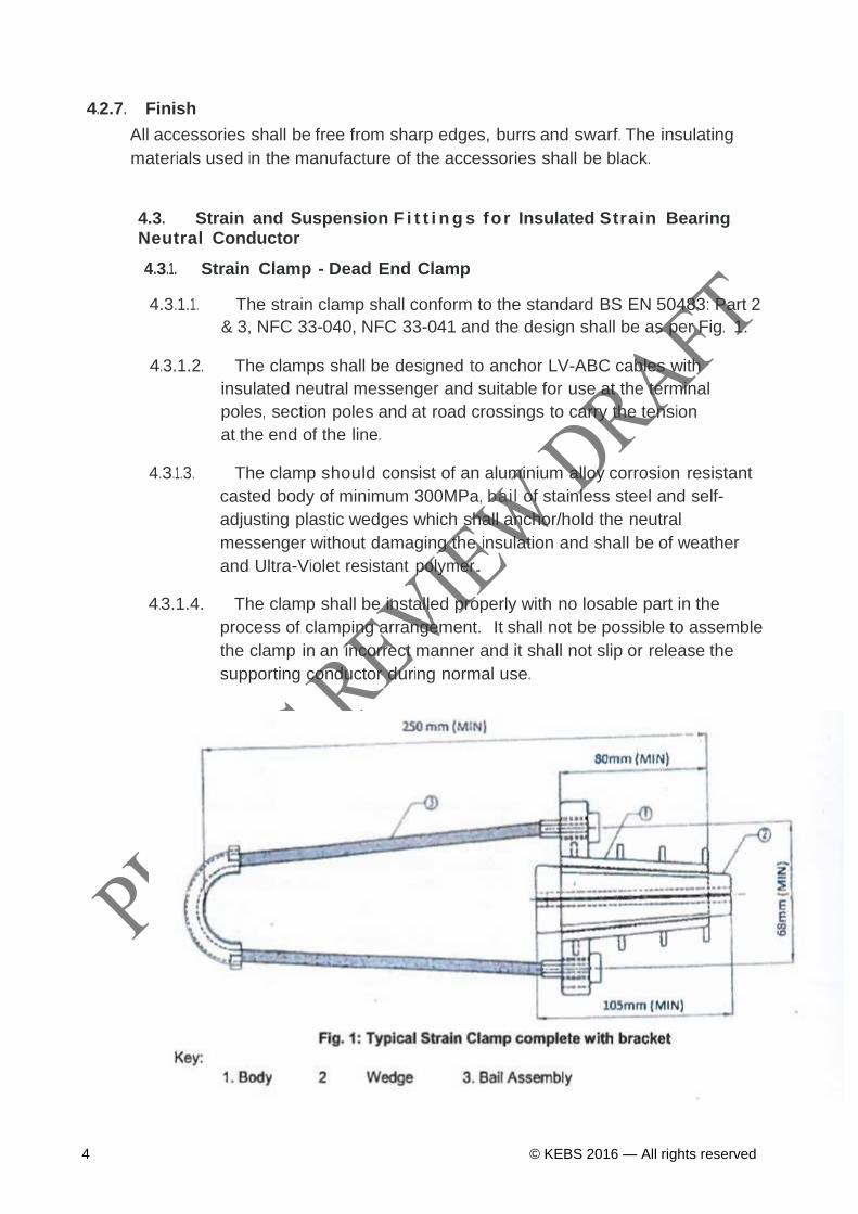
4.3.1.1. The strain clamp shall conform to the standard BS EN 50483: Part 2
& 3, NFC 33-040, NFC 33-041 and the design shall be as per Fig. 1.
4.3.1.2. The clamps shall be designed to anchor LV-ABC cables with
insulated neutral messenger and suitable for use at the terminal
poles, section poles and at road crossings to carry the tension
at the end of the line.
4.3.1.3. The clamp should consist of an aluminium alloy corrosion resistant
casted body of minimum 300MPa, bail of stainless steel and self-
adjusting plastic wedges which shall anchor/hold the neutral
messenger without damaging the insulation and shall be of weather
and Ultra-Violet resistant polymer..
4.3.1.4. The clamp shall be installed properly with no losable part in the
process of clamping arrangement. It shall not be possible to assemble
the clamp in an incorrect manner and it shall not slip or release the
supporting conductor during normal use.
KS 2704:2016
© KEBS 2016 — All rights reserved 5
4.3.1.5. A suspension fitting shall hold the supporting conductor without any
slippage when the conductor is subjected to a force equal to 2.0 % of
breaking force. It shall be designed to release the supporting conductor
by failure at a vertical load of approximately 8 kN as
per Pl ESA 1O18-3 clause 4.6.
4.3.1.6. The clamps shall be fixed to the pole by eye hook (clause 4.3.3) or
bracket (clause 4.3.4).
4.3.1.7. Ultimate tensile strength and slip load of the clamp shall not be less
than the values stated in the Table 1 below.
4.3.1.8. The clamp shall have at least two bolts for tightening and the
hooking end shall be provided with hot dip galvanized nut and bolts with
safety locks.
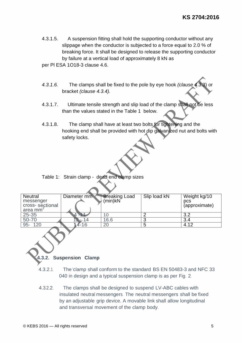
Table 1: Strain clamp - dead end clamp sizes
Neutral messenger cross- sectional area mm2
Diameter mm Breaking Load (min)kN
Slip load kN Weight kg/10 pcs (approximate)
25-35 4 -11 10 2 3.2 50-70 12 - 14 16.6 3 3.4 95- 120 14-16 20 5 4.12
4.3.2. Suspension Clamp
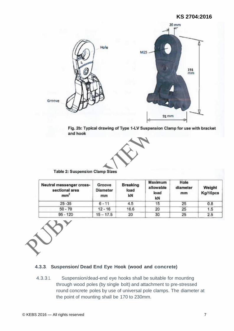
4.3.2.1. The 'clamp shall conform to the standard BS EN 50483-3 and NFC 33
040 in design and a typical suspension clamp is as per Fig. 2.
4.3.2.2. The clamps shall be designed to suspend LV-ABC cables with
insulated neutral messengers. The neutral messengers shall be fixed
by an adjustable grip device. A movable link shall allow longitudinal
and transversal movement of the clamp body.
6 © KEBS 2016 — All rights reserved
4.3.2.3. The clamp shall be installed properly with no losable part in the
process of clamping arrangement.
4.3.2.4. The clamps and the movable links shall be made of weather and
Ultra Violet resistant glass fiber reinforced polymer of at least 1.5mm
thick and shall provide an additional insulation between the cable and
the pole.
4.3.2.5. Clamps shall be fixed to the pole by eye hook (clause 4.3.3) or bracket (clause 4.3.4)
and shall be of a type which can be installed without the use of specialized tools.
4.3.2.6. The ultimate tensile strength and maximum allowable load of the
clamp shall not be less than the values stated in Table 2.
4.3.2.7. The clamp shall sustain a maximum angle of deviation of 60° of the
conductors and shall hold the supporting conductor without any
slippage to within 5% of the specified breaking force of the supporting
conductor.
KS 2704:2016
© KEBS 2016 — All rights reserved 7
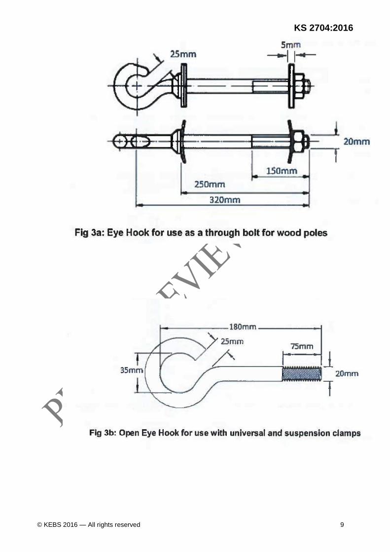
4.3.3. Suspension/ Dead End Eye Hook (wood and concrete)
4.3.3.1. Suspension/dead-end eye hooks shall be suitable for mounting
through wood poles (by single bolt) and attachment to pre-stressed
round concrete poles by use of universal pole clamps. The diameter at
the point of mounting shall be 170 to 230mm.
8 © KEBS 2016 — All rights reserved
4.3.3.2. Eye hooks shall be designed as to hold both suspension clamps and
dead-end clamps and shall be of wood type or concrete type.
4.3.3.3. Eye hooks shall be made of forged hot dip galvanized steel (as per
clause 4.2.3). The manufacture shall not involve cold bending or
welding (or both). They shall be supplied complete with nuts and two
washers as follows: a) Eye Hook for use as a through bolt for wood poles - Fig 3a
(l) Nut M20 x 2
(ii) Round washer M20 x 2 of 5mm thickness (iii) Square curved washer M20 x 2 of 5mm thickness
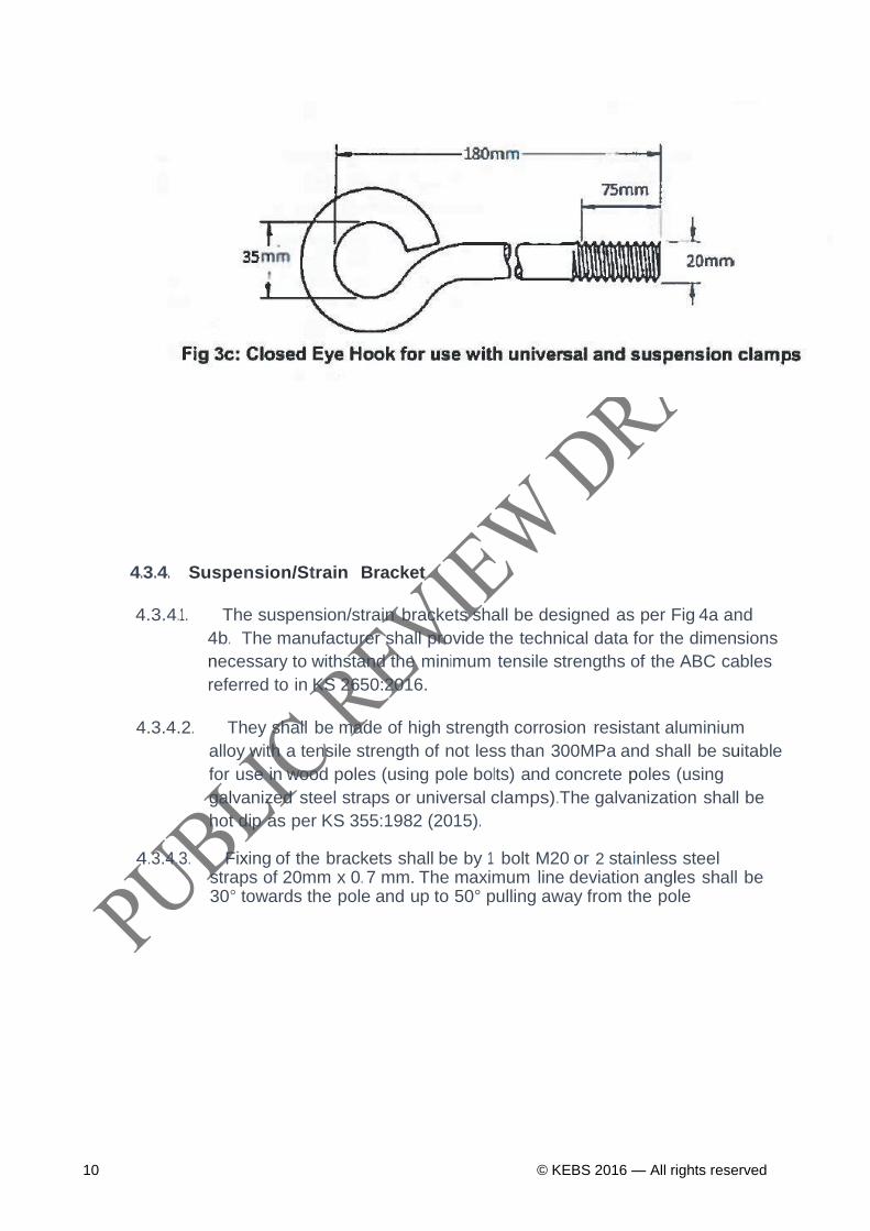
b) Open and closed Eye Hook for use with universal clamps - Fig. 3b & c
(i) Nut M20 x 2 (ii) Round washer M20 x 2 of 3mm thickness (iii) Square washer M20 x 2 of 3mm thickness
4.3.3.4. The bolts and nuts shall be corrosion resistant and the galvanization shall conform to KS 355:1982 (2015).
4.3.3.5. Suspension/dead-end eye hooks shall be manufactured from grade
4.8 material in accordance with ISO 898-1 whereas nuts shall be
manufactured from grade 5 material in accordance with ISO 898-1.
4.3.3.6. External threads shall not be undercut. Galvanizing shall be of type C
of KS 355:1982 (2015)whereas internal threads shall be undercut to
suit matching galvanized components and shall be treated with an
acceptable rust inhibitor. Galvanizing of nuts shall precede threading.
4.3.3. 7. The ultimate tensile strength (UTS) of the eye hook shall be 20 KN. The design and dimensions shall be as per Fig. 3a, b & c.
KS 2704:2016
© KEBS 2016 — All rights reserved 9
10 © KEBS 2016 — All rights reserved
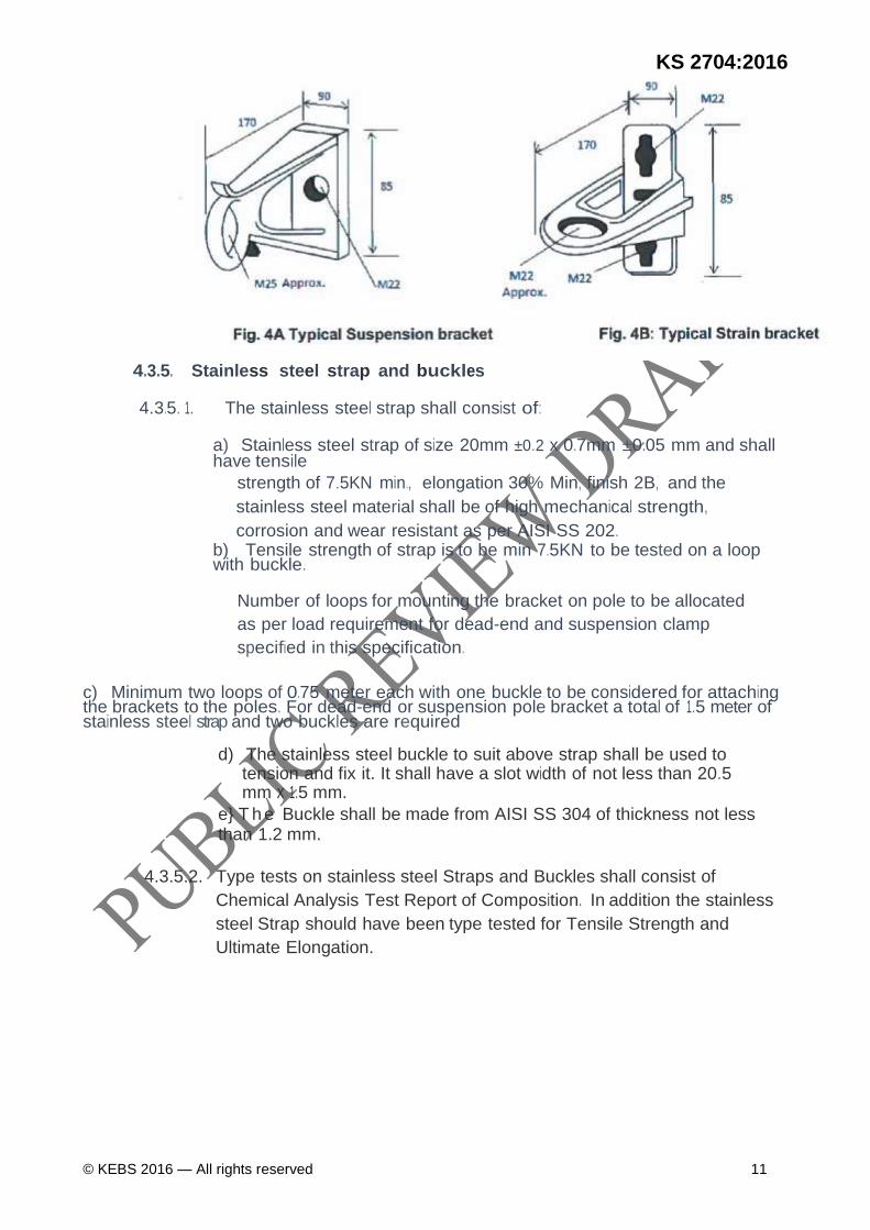
4.3.4. Suspension/Strain Bracket
4.3.4.1. The suspension/strain brackets shall be designed as per Fig 4a and
4b. The manufacturer shall provide the technical data for the dimensions
necessary to withstand the minimum tensile strengths of the ABC cables
referred to in KS 2650:2016.
4.3.4.2. They shall be made of high strength corrosion resistant aluminium
alloy with a tensile strength of not less than 300MPa and shall be suitable
for use in wood poles (using pole bolts) and concrete poles (using
galvanized steel straps or universal clamps).The galvanization shall be
hot dip as per KS 355:1982 (2015).
4.3.4.3. Fixing of the brackets shall be by 1 bolt M20 or 2 stainless steel straps of 20mm x 0. 7 mm. The maximum line deviation angles shall be 30° towards the pole and up to 50° pulling away from the pole
KS 2704:2016
© KEBS 2016 — All rights reserved 11
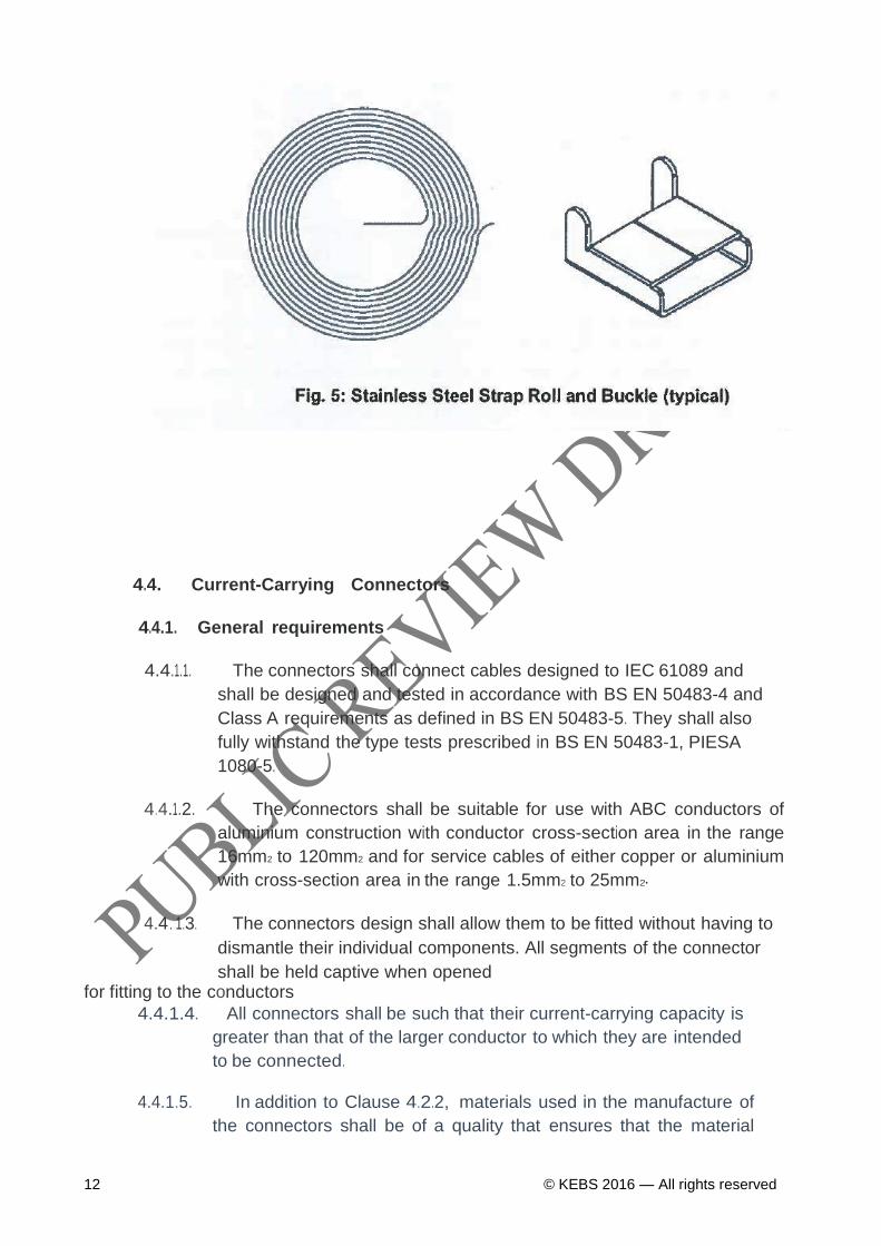
4.3.5. Stainless steel strap and buckles
4.3.5. 1. The stainless steel strap shall consist of:
a) Stainless steel strap of size 20mm ±0.2 x 0.7mm ±0.05 mm and shall have tensile
strength of 7.5KN min., elongation 30% Min, finish 2B, and the
stainless steel material shall be of high mechanical strength,
corrosion and wear resistant as per AISI SS 202. b) Tensile strength of strap is to be min 7.5KN to be tested on a loop with buckle.
Number of loops for mounting the bracket on pole to be allocated
as per load requirement for dead-end and suspension clamp
specified in this specification.
c) Minimum two loops of 0.75 meter each with one buckle to be considered for attaching the brackets to the poles. For dead-end or suspension pole bracket a total of 1.5 meter of stainless steel strap and two buckles are required
d) The stainless steel buckle to suit above strap shall be used to tension and fix it. It shall have a slot width of not less than 20.5 mm x 1.5 mm.
e} T h e Buckle shall be made from AISI SS 304 of thickness not less than 1.2 mm.
4.3.5.2. Type tests on stainless steel Straps and Buckles shall consist of
Chemical Analysis Test Report of Composition. In addition the stainless
steel Strap should have been type tested for Tensile Strength and
Ultimate Elongation.
12 © KEBS 2016 — All rights reserved
4.4. Current-Carrying Connectors
4.4.1. General requirements
4.4.1.1. The connectors shall connect cables designed to IEC 61089 and
shall be designed and tested in accordance with BS EN 50483-4 and
Class A requirements as defined in BS EN 50483-5. They shall also
fully withstand the type tests prescribed in BS EN 50483-1, PIESA
1080-5.
4.4.1.2. The connectors shall be suitable for use with ABC conductors of
aluminium construction with conductor cross-section area in the range
16mm2 to 120mm2 and for service cables of either copper or aluminium
with cross-section area in the range 1.5mm2 to 25mm2•
4.4.. 1.3. The connectors design shall allow them to be fitted without having to
dismantle their individual components. All segments of the connector
shall be held captive when opened for fitting to the conductors
4.4.1.4. All connectors shall be such that their current-carrying capacity is
greater than that of the larger conductor to which they are intended
to be connected.
4.4.1.5. In addition to Clause 4.2.2, materials used in the manufacture of
the connectors shall be of a quality that ensures that the material
KS 2704:2016
© KEBS 2016 — All rights reserved 13
does not split and does not deteriorate from its intended state during
the application process.
4.4.1.6. The connectors shall be designed to withstand physical and
chemical processes expected in service i.e. oxidation, galvanic
corrosion, thermal expansion etc. They shall be UV protected.
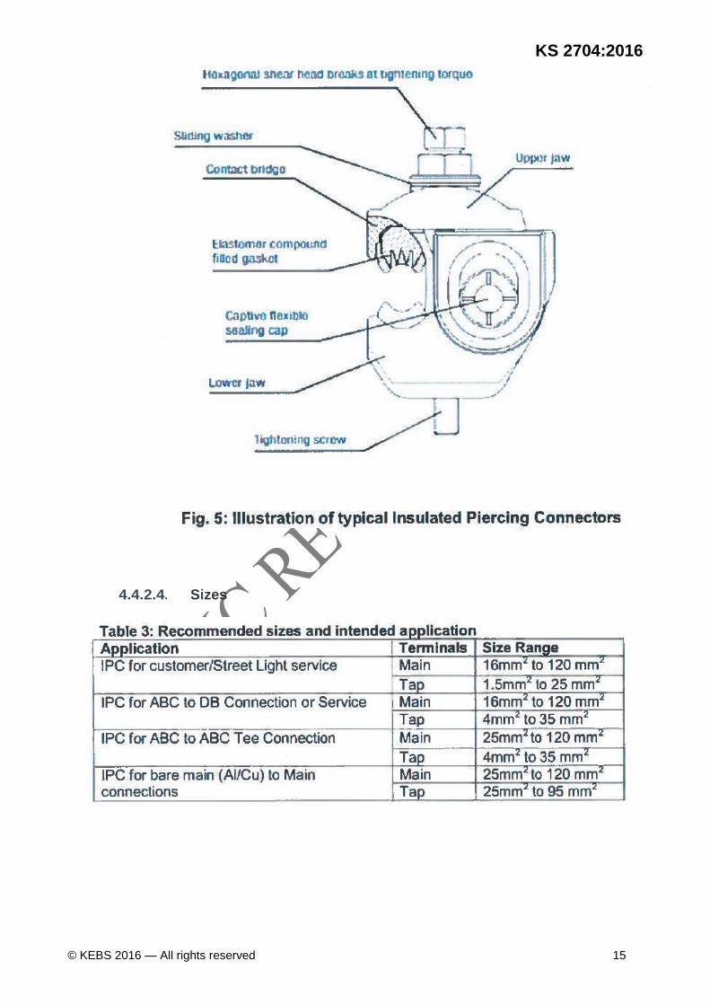
4.4.2. Insulation P i e r c i n g Connectors
4.4.2.1. General
4.4.2.1.1. The insulating piercing connectors (IPC) shall be designed and
tested in accordance with BS EN 50483-1&4, PIESA 1018-5 and
NFC 33-020.The design shall be weather-proof for aluminium
and/or copper main and branch conductors.
4.4.2.1.2. The IPC shall be applicable in the process of replacing the
bare conductors with LV ABC cables to reduce power theft and
line losses by providing a proper method of service connection
from ABC cables to consumers without damaging the cable.
4.4.2.1.3. Removal of bare conductor, stringing of LVABC cable and re-
establishing the service connections shall be done as a
simultaneous process.
4.4.2.1.4. In this regard the IPC shall be used for:-
a) Providing 1-2 service connections from 30 metres away from the pole,
b) providing supply to Junction/ Distribution Box from ABC cable c) Establishing Tee connection from LV ABC to LV ABC cables.
4.4.2.1.5.
This IPC shall. Not be exposed to any bare conductor in the environment
during connection. The design of the connectors shall ensure total
weather and moisture proof so that no water or moisture can enter
through the pierced holes on to the cable
•
Insulation.
4.4.2.1.6.
For individual connectors, the torque required for different conductor
sizes shall be stated in the equipment by the manufacturer.
4.4.2.2. Construction
4.4.2.2.1. The connectors shall be totally insulated with no loose parts. They
shall be totally weather and moisture proof so that no water or
moisture can enter through the pierced holes on the cable insulation.
14 © KEBS 2016 — All rights reserved
4.4.2.2.2. The connectors shall work at 30 cm under water bath for 30 minutes,
and when tested at an applied voltage of 4 KV for 1 minute, there shall
be no flashover/ failure and moisture ingress in it in accordance with
BS EN 50483-1.
4.4.2.2.3. The design shall also withstand working temperatures for installation from -10''C upto
+600·c and operation experience with temperature from -2o·c up to +75•c.
4.4.2.3. Material
Material used in the manufacturing process of the components of this
product shall be specified in the respective product drawings and shall
be summarized as follows:
a) All the metallic part of the connector shall be corrosion resistant and
shall be proven in Salt Fog chamber and Wet S02 gas chamber and
there shall not be any change in contact resistance, temperature
after overloads, load cycling.
b) The body shall be manufactured from corrosion resistant pure aluminium/aluminium alloy with tensile strength of 300MPa.
c) The contact plates shall be made of tinned aluminium/copper. The
connector teeth shall be factory greased and sealed to retard water
or moisture ingress and corrosion.
d) The insulation material shall be made of weather and Ultra
Violet resistance, reinforced polymer in accordance with UL
746-C.
e) The outer metallic part shall have potential free tightening
bolts to allow safe installation on live lines.
f) The bolts shall be made of "Shear Head" type so that it controls the
effective applied torque during installation and break off at a specified
torque after establishing proper connection.
g) The connector shall not have any losable component which may
drop and then lost while installation is taking place at overhead
conditions. The cable end cap shall be
attached to the body.
KS 2704:2016
© KEBS 2016 — All rights reserved 15
4.4.2.4. Sizes
16 © KEBS 2016 — All rights reserved
4.4.3. ABC Bolted Connectors
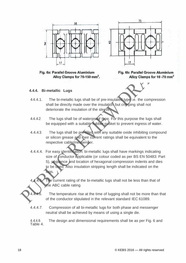
4.4.3.1. Parallel Groove Clamps – Aluminium
This type of bolted connector shall:
a) Be made from forged aluminium; for aluminium to aluminium
connection throughout the conductor range.
b) The clamps shall have serrated transverse grooves for maximum
conductor contact; use hot dip galvanized steel bolts property class
8.8.
c) They shall utilize Belleville washers to prevent thermal ratcheting
under cyclic loads.
d) The clamps shall be coated with an oxide inhibitor.
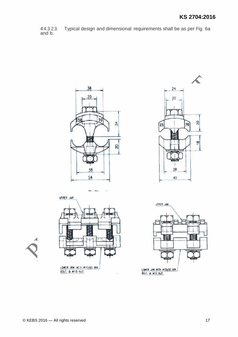
4.4.3.2. Bi-metal Parallel Grooves Clamps
4.4.3.2.1. Bi-Metal parallel groove clamps shall be suitable for tapping or
joining hard drawn or annealed copper conductor or aluminium
overhead conductor type AAC, AAAC or ACSR to the ABC cables.
4.4.3.2.2. Bi-Metal Parallel Groove clamps shall have the following features:
a) They shall be forged from 99.6% pure aluminium clamp with a
friction welded copper insert; clearly marked in blue for making
copper conductor connections. The clamps shall have serrated
transverse grooves for maximum conductor contact.
b) One parallel groove shall have a copper inlay impact welded onto
the surface of the groove, and the external aluminium to copper
interface is sealed by a special compound which prevents interface
corrosion;
c) Slotted bolt holes which allow adjustment to varying conductor sizes
in each groove; tightened onto the conductors using hot dip
galvanized steel bolts, property class 8.8, galvanized nuts that shall
allow the connector to be tightened with the use of a single spanner
at higher torques and utilize belleville washers on bolts to prevent
thermal ratcheting under cyclic load, maintaining clamping pressure,
thus preventing metal creep.
d) The connectors shall be ultrasonically tested to check bonding
between copper inlay and aluminium.
e) The clamps shall be coated with an oxide inhibitor.
KS 2704:2016
© KEBS 2016 — All rights reserved 17
4.4.3.2.3. Typical design and ·dimensional requirements shall be as per Fig. 6a and b.
18 © KEBS 2016 — All rights reserved
4.4.4. Bi-metallic Lugs
4.4.4.1. The bi-metallic lugs shall be of pre-insulated type i.e. the compression
shall be directly made over the insulation but crimping shall not
deteriorate the insulation of the sleeve.
4.4.4.2. The lugs shall be of waterproof type. For this purpose the lugs shall
be equipped with a suitable rubber gasket to prevent ingress of water.
4.4.4.3. The lugs shall be pre-filled with any suitable oxide inhibiting compound
or silicon grease and their current ratings shall be equivalent to the
respective cable/messenger.
4.4.4.4. For easy identification, bi-metallic lugs shall have markings indicating
size of conductor applicable (or colour coded as per BS EN 50483: Part
5), sequence and location of hexagonal compression indents and dies
to be used. Also insulation stripping length shall be indicated on the
lugs.
4.4.4.5. The current rating of the bi-metallic lugs shall not be less than that of
the ABC cable rating.
4.4.4.6. The temperature rise at the time of lugging shall not be more than that
of the conductor stipulated in the relevant standard IEC 61089.
4.4.4.7. Compression of all bi-metallic lugs for both phase and messenger
neutral shall be achieved by means of using a single die.
4.4.4.8. The design and dimensional requirements shall be as per Fig. 6 and Table 4.

KS 2704:2016
© KEBS 2016 — All rights reserved 19
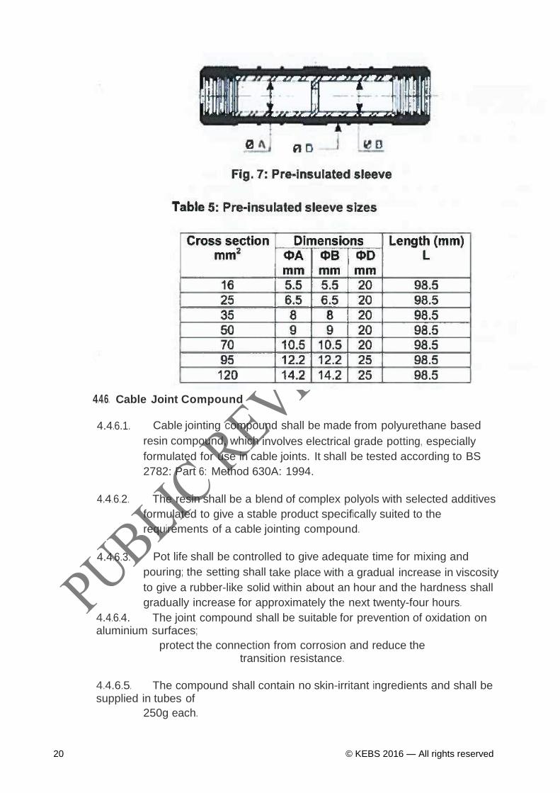
4.4.5. Pre- insulated Sleeves
4.4.5.1. These pre-insulated sleeves shall be used to link together LV insulated overhead lines
(ABC cables up to 1 kV).
4.4.5.2. The sleeves shall compose of:
a) An aluminium (phase) or aluminium alloy (neutral) sleeve with a
stop in the middle. b) A black thermoplastic sealed tube with a flexible
elastomer ring.
c) Neutral contact grease in the tube which improve the contact area and protect the
aluminium against oxidation.
4.4.5.3. The crimping shall be realized on the plastic part according to the
marks on the body of the sleeve.
4.4.5.4 The design and the dimensional requirements shall be as per fig 7 and
table 5
20 © KEBS 2016 — All rights reserved
4.4.6. Cable Joint Compound
4.4.6.1. Cable jointing compound shall be made from polyurethane based
resin compound, which involves electrical grade potting, especially
formulated for use in cable joints. It shall be tested according to BS
2782: Part 6: Method 630A: 1994.
4.4.6.2. The resin shall be a blend of complex polyols with selected additives
formulated to give a stable product specifically suited to the
requirements of a cable jointing compound.
4.4.6.3. Pot life shall be controlled to give adequate time for mixing and
pouring; the setting shall take place with a gradual increase in viscosity
to give a rubber-like solid within about an hour and the hardness shall
gradually increase for approximately the next twenty-four hours.
4.4.6.4. The joint compound shall be suitable for prevention of oxidation on aluminium surfaces;
protect the connection from corrosion and reduce the transition resistance.
4.4.6.5. The compound shall contain no skin-irritant ingredients and shall be supplied in tubes of
250g each.
KS 2704:2016
© KEBS 2016 — All rights reserved 21
4A.6.6. The expiry date of the joint compound shall be quoted and shall
be capable of being stored for not less than 24 months
4.5. End Sealing Caps, Core Separators (pairs) and Cable Ties for use with
Aerial Bundled Conductors
4.5.1. Cable End Sealing Caps
4.5.1.1. End sealing caps shall be insulated and provide protection against
the ingress of moisture and also ensure that the system is fully
insulated. They shall be manufactured and tested as per BS EN 50483.
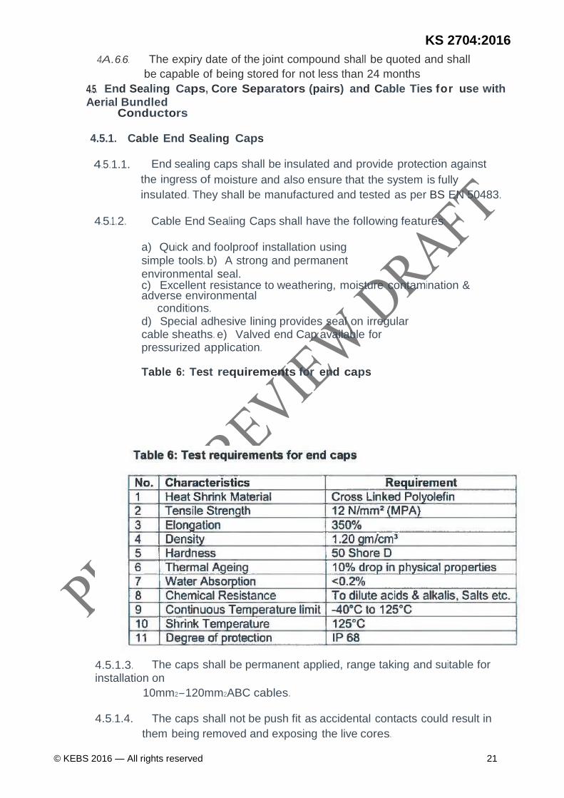
4.5.1.2. Cable End Sealing Caps shall have the following features:
a) Quick and foolproof installation using
simple tools. b) A strong and permanent
environmental seal. c) Excellent resistance to weathering, moisture contamination & adverse environmental
conditions. d) Special adhesive lining provides seal on irregular cable sheaths. e) Valved end Cap available for pressurized application. Table 6: Test requirements for end caps
4.5.1.3. The caps shall be permanent applied, range taking and suitable for
installation on
10mm2-120mm2ABC cables.
4.5.1.4. The caps shall not be push fit as accidental contacts could result in
them being removed and exposing the live cores.

22 © KEBS 2016 — All rights reserved
4.5.1.5. The end sealing cap design and dimensional requirements shall be as per Fig. 8 and
Table 7.
4.5.2. Core Separators (pairs)
KS 2704:2016
© KEBS 2016 — All rights reserved 23
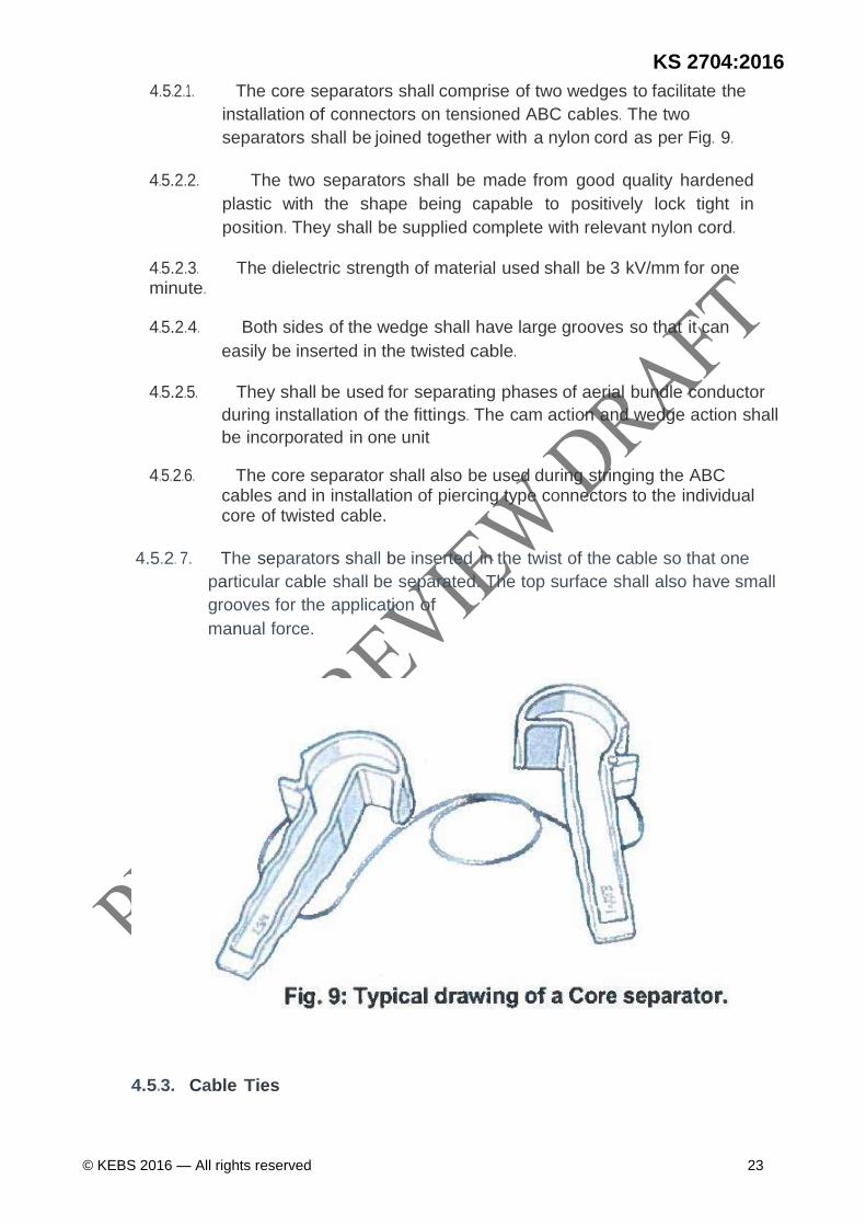
4.5.2.1. The core separators shall comprise of two wedges to facilitate the
installation of connectors on tensioned ABC cables. The two
separators shall be joined together with a nylon cord as per Fig. 9.
4.5.2.2. The two separators shall be made from good quality hardened
plastic with the shape being capable to positively lock tight in
position. They shall be supplied complete with relevant nylon cord.
4.5.2.3. The dielectric strength of material used shall be 3 kV/mm for one minute.
4.5.2.4. Both sides of the wedge shall have large grooves so that it can
easily be inserted in the twisted cable.
4.5.2.5. They shall be used for separating phases of aerial bundle conductor
during installation of the fittings. The cam action and wedge action shall
be incorporated in one unit
4.5.2.6. The core separator shall also be used during stringing the ABC cables and in installation of piercing type connectors to the individual core of twisted cable.
4.5.2. 7. The separators shall be inserted in the twist of the cable so that one
particular cable shall be separated. The top surface shall also have small
grooves for the application of
manual force.
4.5.3. Cable Ties

24 © KEBS 2016 — All rights reserved
4.5.3.1. Cable ties shall be designed as per this specification and tested in accordance with
PIESA 1020.
4.5.3.2. The cable tie shall be heavy duty type single piece assembly of
minimum loop tensile strength of 550N; advanced pawl and teeth
design, with tail finger grips for easier handling and tightening as per
Fig. 10.
4.5.3.3. The cable tie shall be at least 9 mm in width, 350 mm usable length
measured from the inside of the tie clamp and tapered to facilitate
insertion into the tie clamp
4.5.3.4. The cable tie material shall be Polyamide 6.6, coloured black,
weather-stabilized and corrosion resistant and shall pass UL 94 V-2
flammability tests.
4.5.3.5. Cable ties shall be of uniform quality and shall be free from sharp
edges, irregularities or defects that could affect their performance,
reliability or durability.
4.6. Strain and Suspension Fittings for Aerial Service Cables

KS 2704:2016
© KEBS 2016 — All rights reserved 25
4.6.1. House Service Strain Clamp
4.6.1.1 The house service strain clamp shall be designed, manufactured and tested to NFC 33-
042 and shall be type tested to BS EN 50483: Part 2 & 3 standard requirements.
4.6.1.2 The design shall be such that the parts do not separate when the
fittings are being installed on the service cable. Any wedges used
shall be attached to the clamp body.
4.6.1.3 It shall be made from Ultra Violet resistant thermo-plastic body with
the wedge made from hot galvanized steel bail conforming to ISO
1461; that can accommodate round cables from 7 to 19 mm diameter.
4JS.1.4 Strain fittings shall not slip or release the service cable during
normal service and the minimum breaking loads shall be 2.5 kN.
4.6.1.5 Strain fittings shall not cause damage to the service cable during normal service. They shall be of a type that can be installed without the use of special tools.
4.6.1.6 The strain fittings shall be suitable for the tennination of single phase
and three phase service cables of sizes 10 - 16mm2 and 25mm2
respectively.(suitable for use for 2x10 -
2x35 mm2 and 4x16 - 4x25 mm2cables)
4.6.1. 7 The general design of the house strain clamp shall be as per Fig. 11
4.6.2 Pigtail Couch Screw
4.6.2.1 Pigtail couch screw shall be suitable for screwing directly into
wooden pole and for securing into brick wall when used with P16
plastic wall plug.
26 © KEBS 2016 — All rights reserved
4.6.2.2 The screws shall have adequately adjusted threads that shall
withstand a high pull-out resistance and optimum conditions for the
specific field of application.
4.6.2.3 The screws shall be made from hot dip galvanized steel with
minimum tensile strengths conforming to those of the ABC cables
prescribed in clause 4.2.1.1.
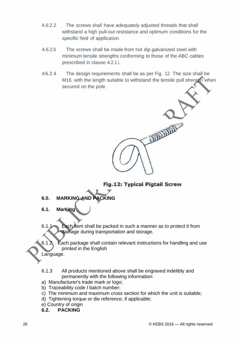
4.6.2.4 The design requirements shall be as per Fig. 12. The size shall be
M16, with the length suitable to withstand the tensile pull strength when
secured on the pole.
6.0. MARKING AND PACKING 6.1. Marking 6.1.1 Each item shall be packed in such a manner as to protect it from
damage during transportation and storage. 6.1.2 Each package shall contain relevant instructions for handling and use
printed in the English Language. 6.1.3 All products mentioned above shall be engraved indelibly and
permanently with the following information: a) Manufacturer's trade mark or logo; b) Traceability code I batch number; c) The minimum and maximum cross section for which the unit is suitable; d) Tightening torque or die reference, if applicable; e) Country of origin 6.2. PACKING
KS 2704:2016
© KEBS 2016 — All rights reserved 27
6.2.1. The Low Voltage ABC accessories shall be suitably packed separately in
reinforced wooden boxes firmly secured with metallic straps and the quantity of items in a package is as in a), b), c), or d) given below.
a) Strain and Suspension Fittings for Aerial Bunched Cables consisting of
insulated Strain Bearing Neutral Messenger Wire - shall be packed separately in reinforced wooden boxes firmly secured with metallic straps.
b) Strain and Suspension Fittings for Aerial Service Cables - shall be packed
separately in reinforced wooden boxes firmly secured with metallic straps.
c) Current-carrying Connectors and Joints - shall be packaged individually in
plastic bag. d) Cable Ties and End Sealing Caps - shall be packaged in plastic bags to
contain moisture and shall remain sealed until ready for use and the quantity of items in a package shall be
100. 6.2.2. Each packing shall be clearly and indelibly marked with the following; a) Name of Item b) Quantity c) Gross Weight d) The boxes shall be marked with manufacturer's identification.