aeon series - projector screen sale - projectors and ... user guide.pdf · aeon series edge free®...
TRANSCRIPT
V072415-EA www.elitescreens.com 1
Aeon Series EDGE FREE® Fixed Frame Projection Screen
User’s Guide
Applies to all available screen materials: CineGrey 3D EDGE FREE® and CineWhite EDGE FREE®
Product Description: The Aeon Series is a fixed frame projection screen that uses Elite’s EDGE FREE™ technology.
The EDGE FREE® design resembles a giant size flat panel TV display. The Aeon includes a velvet tape as an
installation option to further enhance the frame appearance and absorb projector overshoot. An optional LED
backlighting kit is available for added visual appearance.
Assembly Video: For further assistance, watch our assembly and installation video at
www.elitescreens.com/video/aeon-assembly or scan the following QR Code:
For more information on the LED kit please visit: http://www.elitescreens.com/led
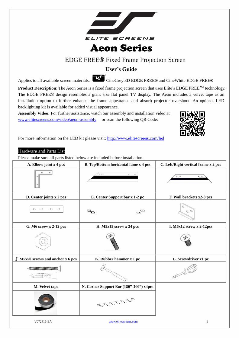
Hardware and Parts List
Please make sure all parts listed below are included before installation.
A. Elbow joint x 4 pcs B. Top/Bottom horizontal fame x 4 pcs C. Left/Right vertical frame x 2 pcs
D. Center joints x 2 pcs E. Center Support bar x 1-2 pc F. Wall brackets x2-3 pcs
G. M6 screw x 2-12 pcs H. M5x15 screw x 24 pcs I. M6x12 screw x 2-12pcs
J. M5x50 screws and anchor x 6 pcs K. Rubber hammer x 1 pc L. Screwdriver x1 pc
M. Velvet tape N. Corner Support Bar (180”-200”) x4pcs

V072415-EA www.elitescreens.com 2
Frame Assembly
1. Insert the center joint into one of the ½ horizontal frames (B) and fasten it with the two M5x15 screws (H).
2. Insert the other ½ horizontal frame piece to the center joint and fasten also using two M5x15 screws.
3. Repeat steps 1 and 2 for assembling the second horizontal frame.
Push Push
4. For models 150” and below, insert and slide in one M6 screw (G) through the channel located on the back
each horizontal frame section (top/bottom).
Note: For models 180” and above, insert and slide in four M6 screws (G) through the channel located on the
back of each horizontal frame section (top/bottom). Insert two M6 screws (G) on each vertical frame section
(left/right).
5. Insert the elbow joint (A) into each end of the horizontal frames (B) as shown below.
Horizontal long frame (B) Elbow Joint (A) Elbow Joint (A)
Horizontal long frame
Face up
M6 hex screws (G)
Horizontal frame
Center Joints
Top right Frame Top left Frame
For models 180” and above, insert four M6 hex screws (G) and see page 8 for proper placement.
For models 150” and below, place one M6 hex screw (G) in the center for attaching the center support bar (E).
V072415-EA www.elitescreens.com 3
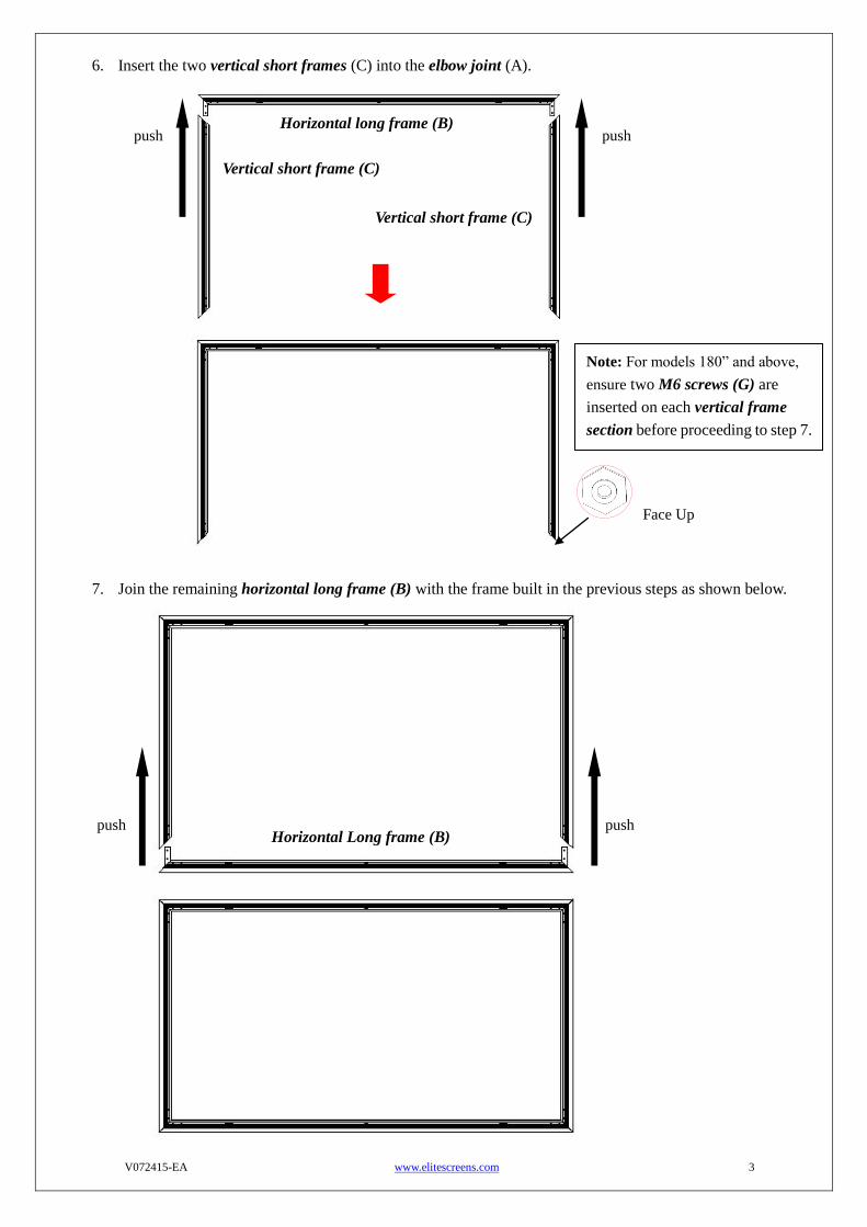
6. Insert the two vertical short frames (C) into the elbow joint (A).
7. Join the remaining horizontal long frame (B) with the frame built in the previous steps as shown below.
Horizontal long frame (B)
Vertical short frame (C)
Horizontal Long frame (B)
push push
push push
Vertical short frame (C)
Note: For models 180” and above,
ensure two M6 screws (G) are
inserted on each vertical frame
section before proceeding to step 7.
Face Up

V072415-EA www.elitescreens.com 4
8. Make sure all four corners are properly in place to form a perfect square. Then fasten the four angles with
the M5x15 Screws (H).
Screen Material Installation
1. Lay the screen material completely flat with the front facing down on a clean surface in a horizontal position. The
back side of the screen material should be placed upwards.
Note: The back side of the material has the velcro borders all around the edges.
2. Carefully and gently place the assembled frame on top the screen material as shown below. Make sure to not allow
the angle edge of the frame to come in direct contact with the screen material to avoid puncturing it.
Four corners join correctly to form a perfect
square. Use the included screwdriver (L) to
fasten the Mx15 screws (H) into each corner
by aligning the frame screw holes to the holes
in the elbow joint (A).
Screen material back facing up
Velcro

V072415-EA www.elitescreens.com 5
3. After all of the corners of the frame have been properly aligned, attach the material to the frame in the following
order A→B→C→D (see instructions below for details).
Attach the screen material to the corners as shown below.
4. After all four corners have been attached; please check whether the frame corners are wrapped by the screen
material. If not, please loosen the velcro connection and repeat the above steps so the frame is not exposed.
Note: The black shaded part represents the velcro on the frame. That Velcro end
will ultimately attach with the other velcro end on the screen material.
Note:
Represents the
screen material
2) Fold over and attach
material to the velcro
strip of the frame.
3) Fold over second side
and attach to frame
4) Repeat until all four
sides are done in the
order A, B, C, D
1) Stretch the screen
material in the direction
of the arrowhead.
D
A D
C B
V072415-EA www.elitescreens.com 6
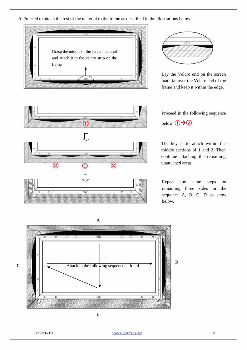
5. Proceed to attach the rest of the material to the frame as described in the illustrations below.
Lay the Velcro end on the screen
material over the Velcro end of the
frame and keep it within the edge.
Proceed in the following sequence
below ①②
The key is to attach within the
middle sections of 1 and 2. Then
continue attaching the remaining
unattached areas.
Repeat the same steps on
remaining three sides in the
sequence A, B, C, D as show
below.
Grasp the middle of the screen material
and attach it to the velcro strip on the
frame
Attach in the following sequence: a-b-c-d
A
B
C D

V072415-EA www.elitescreens.com 7
Screen Material Removal
Follow the steps to properly remove the screen material from the frame. This procedure will ensure prolonging the life
of the screen material.
1. Detach the velcro from the frame.
2. Gently pull back the material to release the material from the velcro connections on the corners
Support bar installation (for models under 180”):
1. Position the center support bar (E) in the middle of the frame and align the hole on each end of the support
bar with the M6 hex screws (G) on the top and bottom frames. Then fasten with the M6x12 screws (I).
Move the M6 hex screw (G) to the middle area of the frames.
Align the M6 screws
with the two holes.
Pull back the screen material from
the velcro connection along the
edges of the frame to detach it.
Support bar
V072415-EA www.elitescreens.com 8
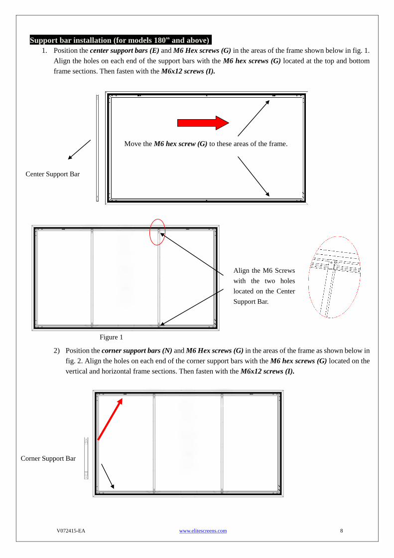
Support bar installation (for models 180” and above):
1. Position the center support bars (E) and M6 Hex screws (G) in the areas of the frame shown below in fig. 1.
Align the holes on each end of the support bars with the M6 hex screws (G) located at the top and bottom
frame sections. Then fasten with the M6x12 screws (I).
2) Position the corner support bars (N) and M6 Hex screws (G) in the areas of the frame as shown below in
fig. 2. Align the holes on each end of the corner support bars with the M6 hex screws (G) located on the
vertical and horizontal frame sections. Then fasten with the M6x12 screws (I).
Center Support Bar
Move the M6 hex screw (G) to these areas of the frame.
Align the M6 Screws
with the two holes
located on the Center
Support Bar.
Corner Support Bar
Figure 1
V072415-EA www.elitescreens.com 9
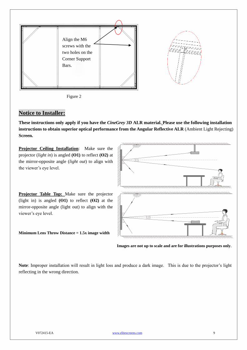
Notice to Installer:
These instructions only apply if you have the CineGrey 3D ALR material. Please use the following installation
instructions to obtain superior optical performance from the Angular Reflective ALR (Ambient Light Rejecting)
Screen.
Projector Ceiling Installation: Make sure the
projector (light in) is angled (ϴ1) to reflect (ϴ2) at
the mirror-opposite angle (light out) to align with
the viewer’s eye level.
Projector Table Top: Make sure the projector
(light in) is angled (ϴ1) to reflect (ϴ2) at the
mirror-opposite angle (light out) to align with the
viewer’s eye level.
Minimum Lens Throw Distance = 1.5x image width
Images are not up to scale and are for illustrations purposes only.
Note: Improper installation will result in light loss and produce a dark image. This is due to the projector’s light
reflecting in the wrong direction.
Align the M6
screws with the
two holes on the
Corner Support
Bars.
Figure 2
V072415-EA www.elitescreens.com 10
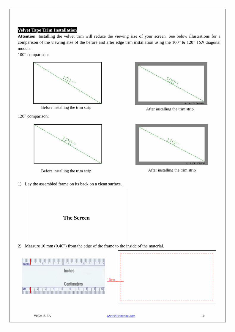
Velvet Tape Trim Installation
Attention: Installing the velvet trim will reduce the viewing size of your screen. See below illustrations for a
comparison of the viewing size of the before and after edge trim installation using the 100” & 120” 16:9 diagonal
models.
100” comparison:
120” comparison:
1) Lay the assembled frame on its back on a clean surface.
2) Measure 10 mm (0.40”) from the edge of the frame to the inside of the material.
The Screen
Before installing the trim strip After installing the trim strip
After installing the trim strip
Before installing the trim strip
V072415-EA www.elitescreens.com 11
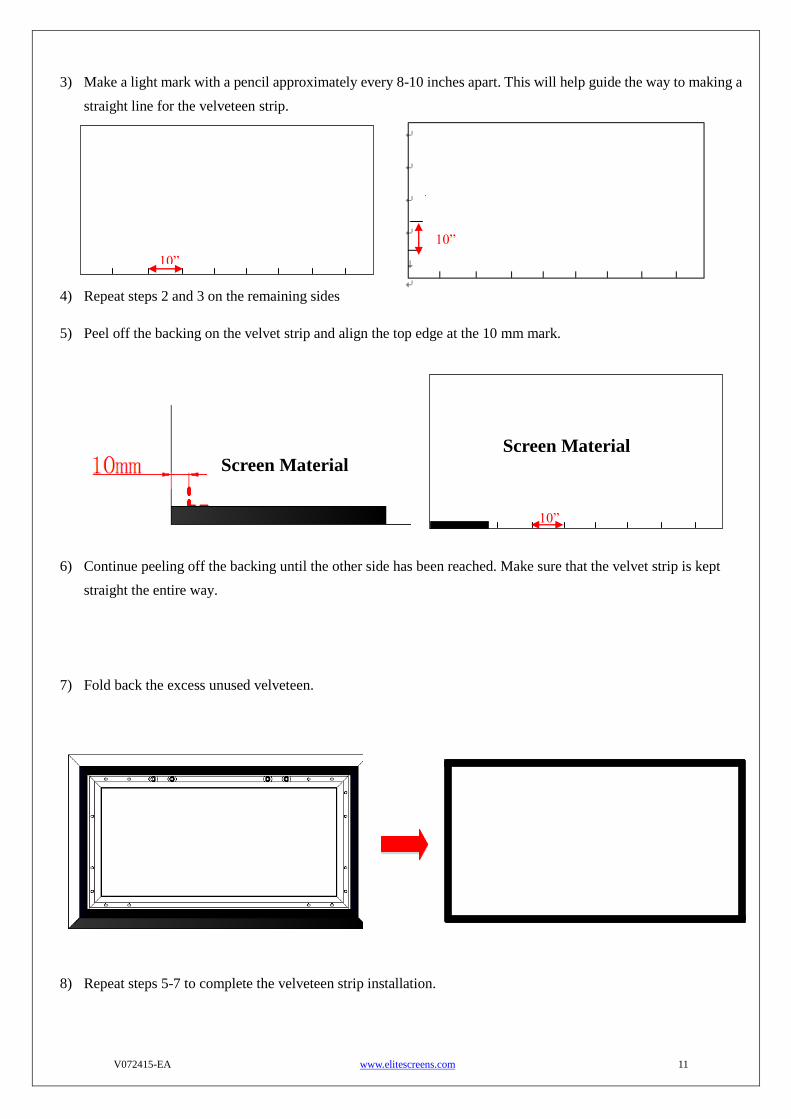
3) Make a light mark with a pencil approximately every 8-10 inches apart. This will help guide the way to making a
straight line for the velveteen strip.
4) Repeat steps 2 and 3 on the remaining sides
5) Peel off the backing on the velvet strip and align the top edge at the 10 mm mark.
6) Continue peeling off the backing until the other side has been reached. Make sure that the velvet strip is kept
straight the entire way.
7) Fold back the excess unused velveteen.
8) Repeat steps 5-7 to complete the velveteen strip installation.
Screen Material Screen Material
10”
10”
10”

V072415-EA www.elitescreens.com 12
Installation
Locate your desired installation location with a stud finder (recommended) and mark the drill-hole area of where the
screen is to be installed.
1. Drill a hole with the proper bit size according to the wood screws included.
2. Line up the wall brackets with the drilled holes on the installation location and screw them in using a Phillips
screwdriver.
3. Position the frame screen onto the wall brackets (F) as shown in below.
4. The design of the wall brackets allows the frame to slide over them through its sides. This is an important
feature of the installation design as it allows your screen to be properly centered.
For a local Elite Screens contact or Technical Support, please visit
www.elitescreens.com