aem fuel pumps installation instructions - carid.com · the infinity ecu supports the factory cas...
TRANSCRIPT

P/N 30-35151989-1998 Nissan Skyline GT-R
RB26DETTAEM Infinity PnP Harness
InstructionManual
WARNING: This installation is not for the tuning novice! Use this system with EXTREME caution! The AEM Infinity Programmable EMS allows for total flexibility in engine tuning. Misuse or improper tuning of this product can destroy your engine! If you are not well versed in engine dynamics and the tuning of engine management systems DO NOT attempt the installation.
NOTE: All supplied AEM calibrations, Wizards and other tuning information are offered as potentialstarting points only. IT IS THE RESPONSIBILITY OF THE ENGINE TUNER TO ULTIMATELY CONFIRM IF THECALIBRATION IS SAFE FOR ITS INTENDED USE. AEM holds no responsibility for any engine damage thatresults from the misuse or mistuning of this product!
STOP!
THIS PRODUCT HAS LEGAL RESTRICTIONS. READ THIS BEFORE INSTALLING/USING!
IT IS THE RESPONSIBILITY OF THE INSTALLER AND/OR USER OF THIS PRODUCT TO ENSURE THAT IT IS USED IN COMPLIANCE WITH
ALL APPLICABLE LAWS AND REGULATIONS. IF THIS PRODUCT WAS PURCHASED IN ERROR, DO NOT INSTALL AND/OR USE IT. THE
PURCHASER MUST ARRANGE TO RETURN THE PRODUCT FOR A FULL REFUND.
THIS POLICY ONLY APPLIES TO INSTALLERS AND/OR USERS WHO ARE LOCATED IN THE UNITED STATES; HOWEVER CUSTOMERS
WHO RESIDE IN OTHER COUNTRIES SHOULD ACT IN ACCORDANCE WITH THEIR LOCAL LAWS AND REGULATIONS.
P/N 30-3515
OVERVIEWThe 30-3515 AEM Infinity PnP Harness Adapter was designed to run 1989-1998 Nissan Skyline GT-R withRB26DETT engines. This is a true standalone system that eliminates the use of the Nissan ECU and mass airflowsensors. The Infinity ECU supports the factory CAS (Cam Angle Sensor), so replacing the disk within the CAS is not required. The use of this harness makes the kit “plug and play” so no cutting or splicing wires is necessary(when used with optional 30-3510-00 AUX harness, sold separately). The base configuration files available for theInfinity EMS are starting points only and will need to be modified for every specific application.
The available Infinity EMS part numbers for this adapter kit are:· 30-7106 INFINITY-6· 30-7108 INFINITY-8h* (*Use of this ECU will result in the loss of certain functions- VTC Solenoid and MIL.
Refer to Pinout below for details.)
Please read this document in its entirety before attempting to start or run an engine.
GETTING STARTEDRefer to the 10-7100 for EMS 30-7100 Infinity Quick Start Guide for additional information on gettingthe engine started with the Infinity EMS. The base session is located in C:\Documents\AEM\Infinity Tuner\Sessions\Base Sessions.
DOWNLOADABLE FILES
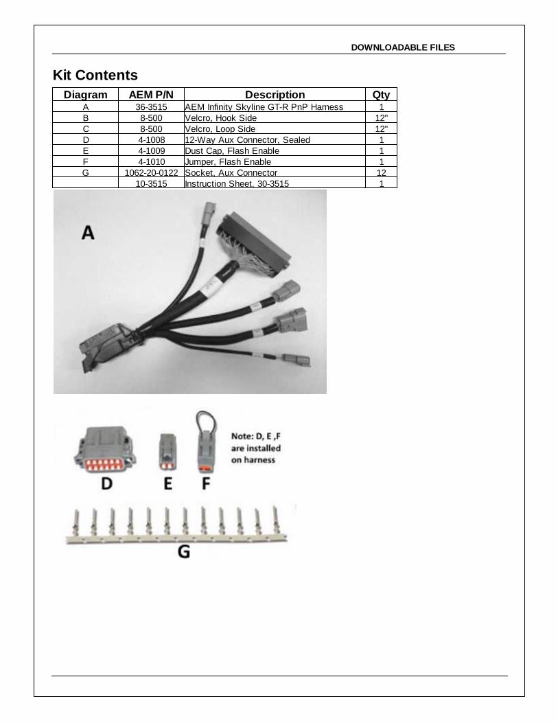
Kit Contents
Diagram AEM P/N Description QtyA 36-3515 AEM Infinity Skyline GT-R PnP Harness 1B 8-500 Velcro, Hook Side 12"C 8-500 Velcro, Loop Side 12"D 4-1008 12-Way Aux Connector, Sealed 1E 4-1009 Dust Cap, Flash Enable 1F 4-1010 Jumper, Flash Enable 1G 1062-20-0122 Socket, Aux Connector 12
10-3515 Instruction Sheet, 30-3515 1
P/N 30-35154
© 2015 AEM Performance Electronics
Important Application NotesThe 30-3515 AEM Infinity PnP Harness allows for a "plug and play" installation of either an AEM Infinity-6 orInfinity-8h* ECU to a 1989-1998 Nissan Skyline equipped with one of the following engines:
1989-1998 RB26DETT 2.6L DOHC I-6, Twin Turbo1989-1994 RB20DET 2.0L DOHC I-6, Single Turbo1993-1998 RB25DET 2.5L DOHC I-6, Single Turbo
*Use of the Infinity-8h ECU will result in the loss of certain functions- VTC Solenoid and MIL. Refer to Pinout belowfor details.
The AEM Infinity ECU will run the engine with a speed density fueling calculation, eliminating the need for an OEMairbox and mass airflow sensor (MAF). Required are an intake air temperature (IAT) sensor and manifold absolutepressure (MAP) sensor. AEM also offers an auxiliary sub-harness to make adding these sensors a plug and playinstallation.
30-2010 Air Temp Sensor Kit, 3/8" NPT30-2130-50 3.5bar (50PSIa) Stainless Steel MAP Sensor Kit30-3510-00 Auxiliary Harness for AEM MAP and IAT Sensors
The AEM Infinity ECU includes on board control for one UEGO wideband oxygen sensor. This sensor connects tothe AEM Infinity PnP Harness via a 6-pin DTM-style plug. AEM offers a UEGO extension harness that is 72" longand will connect the UEGO sensor to the PnP harness.
30-2001 Bosch LSU 4.2 Wideband UEGO Replacement Sensor 30-3600 Infinity O2 Sensor Extension Harness (72")
The AEM Infinity ECU supports the OEM Nissan Cam Angle Sensor (CAS) '360 Degree' pattern. The base sessionis pre-configured and will sync close enough for startup with the OEM CAS disk. Previous AEM ECUs may haverequired the CAS trigger disk to be replaced with an AEM-supplied disk that has a 12 crank / 1 cam pattern. If theengine already has one of these AEM disks installed, the Infinity ECU may be reconfigured via the Setup Wizard toproperly read this pattern. In the Cam/Crank section of the Setup Wizard, select sensor type Universal 12 HallCrank & 1 Hall Cam. The timing will need to be sync'd with a timing light before attempting to fire the engine.Refer to the Infinity User Guide for detailed instructions on setting up a universal Cam/Crank pattern.
The AEM Infinity PnP harness includes a dedicated TPS signal output circuit for use with Skyline GT-R auxiliarydevices (ATTESA AWD control and dashboard display). This output signal is located at pin 56 of the Nissan ECUconnector for plug and play operation of these devices. The output signal will directly follow the TPS voltage as it iscalibrated via the Set Throttle Range section of the Setup Wizard.
Many Nissan wiring harnesses have been found to contain significant differences between model yearsand/or trim levels. Likely differences include: Crank signal, Cam signal, Ignition switch wiring (theIgnition switch input controls the Main Relay output), injector and coil destinations. Officialdocumentation for many of these vehicles was not offered in English, so it would be very wise to double-check the pinout destinations for these circuits. This is especially true if the vehicle contains a ‘swapped’engine or if the wiring harness has been cut, spliced, soldered, re-routed, re-pinned or modified in anyother manner. It is the user’s responsibility to check that the wiring on the vehicle matches the pinoutchart contained in this instruction manual.

Important Application Notes
INFINITY ADAPTER HARNESSThe AEM Infinity Plug and Play Harness connects between the OEM Nissan harness and the AEM Infinity ECU,completely replacing the OEM ECU. The harness connections for the various sensors and auxiliary options aredescribed here.
P/N 30-3515
Connections
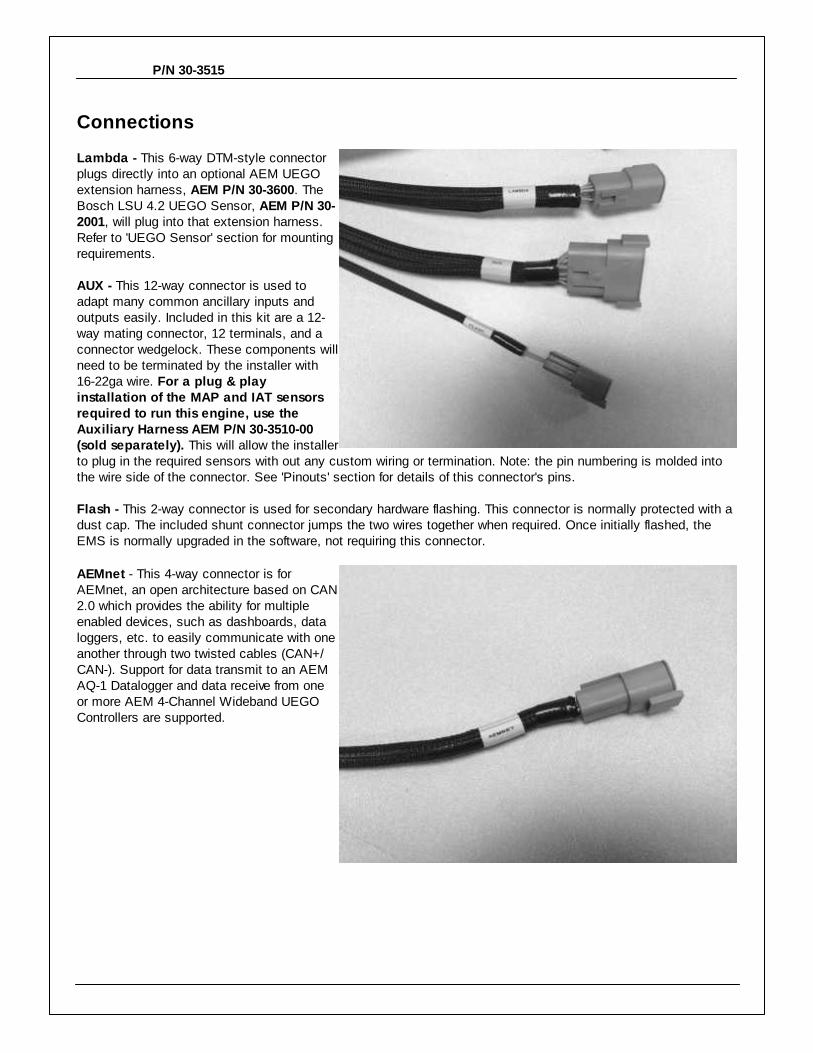
Lambda - This 6-way DTM-style connectorplugs directly into an optional AEM UEGOextension harness, AEM P/N 30-3600. TheBosch LSU 4.2 UEGO Sensor, AEM P/N 30-2001, will plug into that extension harness.Refer to 'UEGO Sensor' section for mountingrequirements.
AUX - This 12-way connector is used toadapt many common ancillary inputs andoutputs easily. Included in this kit are a 12-way mating connector, 12 terminals, and aconnector wedgelock. These components willneed to be terminated by the installer with16-22ga wire. For a plug & playinstallation of the MAP and IAT sensorsrequired to run this engine, use theAuxiliary Harness AEM P/N 30-3510-00(sold separately). This will allow the installerto plug in the required sensors with out any custom wiring or termination. Note: the pin numbering is molded intothe wire side of the connector. See 'Pinouts' section for details of this connector's pins.
Flash - This 2-way connector is used for secondary hardware flashing. This connector is normally protected with adust cap. The included shunt connector jumps the two wires together when required. Once initially flashed, theEMS is normally upgraded in the software, not requiring this connector.
AEMnet - This 4-way connector is forAEMnet, an open architecture based on CAN2.0 which provides the ability for multipleenabled devices, such as dashboards, dataloggers, etc. to easily communicate with oneanother through two twisted cables (CAN+/CAN-). Support for data transmit to an AEMAQ-1 Datalogger and data receive from oneor more AEM 4-Channel Wideband UEGOControllers are supported.
Installation
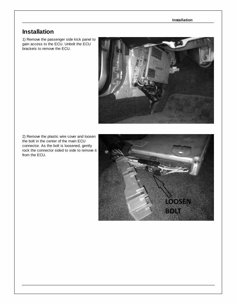
Installation1) Remove the passenger side kick panel togain access to the ECU. Unbolt the ECUbrackets to remove the ECU.
2) Remove the plastic wire cover and loosenthe bolt in the center of the main ECUconnector. As the bolt is loosened, gentlyrock the connector sided to side to remove itfrom the ECU.

P/N 30-3515
3) Insert the OEM wire harness connectorinto the AEM Infinity PnP adapter harness.Gently tighten the bolt and draw theconnector into the adapter harness. Makesure the connector does not skew to oneside. Verify the connector is fully seated andsnug the bolt. Do not force the connector, donot over tighten the bolt.
4) Plug in the additional connectors to theAEM Infinity PnP harness. The 12-pin AUXconnector will need to be terminated for theIAT and MAP sensors, or use AEM p/n 30-3510-00 Infinity AUX Harness (soldseparately) for a simple plug and playinstallation. Refer to schematic for wiringMAP and IAT sensors into 12-pin AUX plugat end of this document if constructing yourown harness.
The 6-pin LAMBDA connector plugs into the30-3600 Infinity O2 Sensor ExtensionHarness (sold separately) to mate with theoptional 30-2001 Bosch LSU 4.2 WidebandUEGO Replacement Sensor (also soldseparately). Route these harnesses throughthe firewall to the appropriate sensors andsecure out of the way of hot or moving parts.

Installation
5) Plug in the 80-pin connector to the InfinityECU. Swing the latch over to draw theconnector down into position. The latch willclick in position. Slide the the red lock intoplace to secure the latch. Use the suppliedVelcro strips to secure the ECU into placebehind the kick panel.

P/N 30-3515
PINOUTS
Infinity-6 P/N 30-7106, Infinity-8h P/N 30-7108*Infinity
PinHardwareReference
NissanFunction
NissanPin Destination
Hardware Specification Notes
C1-1 LowsideSwitch_4A/C
CompressorC2-9
Lowside switch, 1.7A max, NO
internal f ly back diode. 12v pullup.
Conf igured in Base Session f or A/C Compressor Clutch
control. May be reassigned in Setup Wizard Output
Function Assignments.
C1-2 LowsideSwitch_5 Tacho C2-7
Lowside switch, 6A max with internal
f ly back diode. Inductiv e load should
NOT hav e f ull time power. 12v
pullup.
Conf igured in Base Session f or tachometer signal. May
be reassigned in Setup Wizard Output Function
Assignments.
C1-3LowsideSwitch_6
(Inf inity -6 ONLY)VTC Solenoid C2-113
Lowside switch, 6A max with internal
f ly back diode. Inductiv e load should
NOT hav e f ull time power. No
pullup.
Conf igured in Base Session f or VTC Solenoid Valv e
control. May be reassigned in Setup Wizard Output
Function Assignments.
C1-3* Injector 7
(Inf inity -8h ONLY)
--- --- For use with high impedance (10-
15ohms) injectors only , 1.7A max.Av ailable.
C1-4LowsideSwitch_7
(Inf inity -6 ONLY)MIL C2-32
Lowside switch, 6A max no internal
f ly back diode. No pullup.
Conf igured in Base Session f or Malf unction Indicator
Light control. May be reassigned in Setup Wizard Output
Function Assignments.
C1-4* Injector 8
(Inf inity -8h ONLY)
--- --- For use with high impedance (10-
15ohms) injectors only , 1.7A max.Av ailable.
C1-5 UEGO 1 Heat --- C5-4
Bosch UEGO controller
Terminated at 6-pin “Lambda” connector f or connecting
an Inf inity UEGO Extension harness (AEM 30-3600) and
UEGO wideband Bosch LSU4.2 sensor (AEM 30-2001).
C1-6 UEGO 1 IA --- C5-6
C1-7 UEGO 1 IP --- C5-1
C1-8 UEGO 1 UN --- C5-2
C1-9 UEGO 1 VM --- C5-5
C1-10 Batt Perm PowerPermanent
PowerC2-58 Dedicated power management CPU
Full time battery power. MUST be powered bef ore the
ignition switch input is triggered.
C1-11 Coil 4 Coil 4 C2-13 25 mA max source current0-5V Falling edge fire. DO NOT connect directly tocoil primary.
C1-12 Coil 3 Coil 3 C2-3 25 mA max source current0-5V Falling edge fire. DO NOT connect directly tocoil primary.
C1-13 Coil 2 Coil 2 C2-12 25 mA max source current0-5V Falling edge fire. DO NOT connect directly tocoil primary.
C1-14 Coil 1 Coil 1 C2-1 25 mA max source current0-5V Falling edge fire. DO NOT connect directly tocoil primary.
C1-15 Coil 6 Coil 6 C2-11 25 mA max source current0-5V Falling edge fire. DO NOT connect directly tocoil primary.
C1-16 Coil 5 Coil 5 C2-2 25 mA max source current0-5V Falling edge fire. DO NOT connect directly tocoil primary.
C1-17Crank Position
Sensor VR+--- ---
Dif f erential Variable Reluctance
Zero Cross DetectionNot used.
C1-18Crank Position
Sensor VR---- ---
C1-19Cam Position
Sensor 1 VR---- ---
Dif f erential Variable Reluctance
Zero Cross DetectionNot used.
C1-20Cam Position
Sensor 1 VR+--- ---
C1-21 LowsideSwitch_2Cooling Fan
RelayC2-6
Lowside switch, 1.7A max, NO
internal f ly back diode. No pullup.
May be adjusted under Coolant Fan 1 options in Setup
Wizard.
C1-22 LowsideSwitch_3 AAC Valv e C2-4
Lowside switch, 6A max with internal
f ly back diode. Inductiv e load should
NOT hav e f ull time power. No
pullup.
Conf igured in Base Session f or Idle Air Control (AAC)
Valv e control. May be reassigned in Setup Wizard
Output Function Assignments.
C1-23 AGND Sensor C2-30 Dedicated analog ground Sensor ground f or 0-5v analog inputs.

PINOUTS
Ground
C1-24 AGNDSensor
GroundC3-3 Dedicated analog ground Sensor ground f or 0-5v analog inputs.
C1-25Crank Position
Sensor 1 HallCrank Signal C2-42, C2-52
10K pullup to 12V. Will work with
ground or f loating switches.
Frequency input only .
See Setup Wizard Cam/Crank page f or options.
C1-26Cam Position
Sensor 1 HallCam Signal C2-41, C2-51
10K pullup to 12V. Will work with
ground or f loating switches.
Frequency input only .
See Setup Wizard Cam/Crank page f or options.
C1-27 Digital_In_2 --- ---10K pullup to 12V. Will work with
ground or f loating switches.
Frequency input only .
Not used.
C1-28 Digital_In_3 --- C3-910K pullup to 12V. Will work with
ground or f loating switches.
Frequency input only .
Av ailable f requency input. May be used f or Flex Fuel,
Turbo Speed, or other. See Setup Wizard to conf igure
input.
C1-29 Digital_In_4Vehicle Speed
InputC2-53
10K pullup to 12V. Will work with
ground or f loating switches.
Frequency input only .
Conf igured in Base Session f or v ehicle speed. May be
adjusted under Vehicle Speed Input options in Setup
Wizard.
C1-30 Digital_In_5 A/C Switch C2-4310K pullup to 12V. Will work with
ground or f loating switches. Switch
input only .
Conf igured in Base Session f or A/C Switch. May be
reassigned in Setup Wizard Input Function Assignments.
C1-31Digital_In_6
(Inf inity -6 ONLY)--- ---
10K pullup to 12V. Will work with
ground or f loating switches.
Frequency input only .
Av ailable f requency input. May be used f or Flex Fuel,
Turbo Speed, or other. See Setup Wizard to conf igure
input.
C1-31* Coil 7
(Inf inity -8h ONLY)
--- --- 25 mA max source currentNot used.
C1-32Digital_In_7
(Inf inity -6 ONLY)--- C3-10
10K pullup to 12V. Will work with
ground or f loating switches. Switch
input only .
Av ailable switch input. May be used f or Clutch, Brake,
Nitrous, or other. See Setup Wizard to conf igure input.
C1-32* Coil 8
(Inf inity -8h ONLY)
--- --- 25 mA max source currentNot used.
C1-33 Power Ground Ground C2-10 Power ground Power ground.
C1-34 CAN A- --- C5-2Dedicated high speed CAN
transceiv er
Four pin AEMnet connector in PnP harness. Transmit
and receiv e to/f rom AEM AQ-1 logger, 4-channel UEGO
controller, and third party dash display s.
C1-35 CAN A+ --- C5-1Dedicated high speed CAN
transceiv er
Four pin AEMnet connector in PnP harness. Transmit
and receiv e to/f rom AEM AQ-1 logger, 4-channel UEGO
controller, and third party dash display s.
C1-36 CAN B- --- ---Dedicated high speed CAN
transceiv erNot used.
C1-37 CAN B+ --- ---Dedicated high speed CAN
transceiv erNot used.
C1-38 Temp 1Coolant Temp
SensorC2-28 2.49k pullup to 5v See Setup Wizard Coolant Temperature page f or options.
C1-39 Temp 2Air Temp
SensorC3-2 2.49k pullup to 5v
Must wire IAT sensor to AUX plug in PnP harness. See
Setup Wizard Basic Sensors page f or options.
C1-40 Temp 3 --- C3-7 2.49k pullup to 5vAv ailable temperature input. May be used f or Oil
Temperature input or other. See Setup Wizard Input
Function Assignments.
C1-41 LowsideSwitch_0 Fuel Pump C2-18Lowside switch, 4A max, NO internal
f ly back diode. No pullup.
Switched ground. Will prime f or 2 seconds at key on
and activ ate if RPM > 0.
C1-42 LowsideSwitch_1 Boost Control C2-25
Lowside switch, 4A max with internal
f ly back diode. Inductiv e load should
NOT hav e f ull time power. No
pullup.
Base session conf igured to driv e boost control solenoid.
May be reassigned in Setup Wizard Output Function
Assignments.
C1-43 Power Ground Ground C2-20 Power ground Power ground.
C1-44 Knock Sensor 1 Knock1 C2-23 Dedicated knock signal processor See Setup Wizard Knock Setup page f or options.
C1-45 Knock Sensor 2 Knock2 C2-24 Dedicated knock signal processor See Setup Wizard Knock Setup page f or options.
C1-46 Power Ground Ground C2-50 Power ground Power ground.
C1-47Main Relay
Control
Ground out to
main relayC2-16
0.7A max ground sink f or external
relay control
Will activ ate at key on and at key of f according to the
conf iguration settings.

P/N 30-3515
C1-48 Ign Switch Ignition Switch C2-45 10k pulldownFull time battery power must be av ailable at C1-10
bef ore this input is triggered.
C1-49 +5V_Out+5V Sensor
PowerC2-48
Regulated, f used +5V supply f or
sensor powerAnalog sensor power.
C1-50 +5V_Out+5V Sensor
PowerC3-4
Regulated, f used +5V supply f or
sensor powerAnalog sensor power.
C1-51 Analog_In_7Throttle
PositionC2-38 12 bit A/D, 100K pullup to 5V Conf igured f or TPS input f rom OEM throttle body .
C1-52 Analog_In_8MAP
SensorC3-5 12 bit A/D, 100K pullup to 5V
Must wire MAP sensor to AUX plug in PnP harness. See
Setup Wizard Basic Sensors page f or options.
C1-53 Analog_In_9 Fuel Pressure C3-9 12 bit A/D, 100K pullup to 5VWire optional Fuel Pressure sensor to AUX plug in PnP
harness. See Setup Wizard Basic Sensors page f or
options.
C1-54 VR+_In_2 --- --- Dif f erential Variable Reluctance
Zero Cross Detection
Av ailable f or use as Non-driv en wheel speed input. See
Setup Wizard Input Function Assignments.C1-55 VR-_In_2 --- ---
C1-56 VR-_In_3 --- --- Dif f erential Variable Reluctance
Zero Cross Detection
Av ailable f or use as Driv en wheel speed input. See
Setup Wizard Input Function Assignments.C1-57 VR+_In_3 --- ---
C1-58 HighsideSwitch_0 --- ---2.6A max, High Side Solid State
Relay
Av ailable +12V switched output. See Setup Wizard
Output Function Assignments to conf igure.
C1-59 Stepper_1B --- ---Automotiv e, Programmable Stepper
Driv er, up to 28V and ±1.4ANot used.
C1-60 Stepper_2B --- ---Automotiv e, Programmable Stepper
Driv er, up to 28V and ±1.4ANot used.
C1-61 DBW1 Motor- --- ---5.0A max Throttle Control Hbridge
Driv eNot used.
C1-62 DBW1 Motor+ --- ---5.0A max Throttle Control Hbridge
Driv eNot used.
C1-63 +12v +12v C2-49, C4-3 12v power f rom main relay 12v power f rom main relay .
C1-64 Injector 6 Injector 6 C2-112Saturated or peak and hold, 3A max
continuous.Injector 6.
C1-64* Injector 6
(Inf inity -8h ONLY)
Injector 6 C2-112 For use with high impedance (10-
15ohms) injectors only , 1.7A max.Injector 6.
C1-65 Injector 5 Injector 5 C2-110Saturated or peak and hold, 3A max
continuous.Injector 5.
C1-65* Injector 5
(Inf inity -8h ONLY)
Injector 5 C2-110 For use with high impedance (10-
15ohms) injectors only , 1.7A max.Injector 5.
C1-66 Injector 4 Injector 4 C2-114Saturated or peak and hold, 3A max
continuous.Injector 4.
C1-66* Injector 4
(Inf inity -8h ONLY)
Injector 4 C2-114 For use with high impedance (10-
15ohms) injectors only , 1.7A max.Injector 4.
C1-67 Power Ground Ground C2-60, C5-4 Power ground Power ground.
C1-68 +12v +12vC2-59, C3-8,
C5-312v power f rom main relay 12v power f rom main relay .
C1-69 Analog_In_19 --- --- 12 bit A/D, 100K pullup to 5VAv ailable analog input. May be used f or External UEGO
Lambda input or other. See Setup Wizard Input Function
Assignments.
C1-70 Analog_In_18 --- --- 12 bit A/D, 100K pullup to 5VAv ailable analog input. May be used f or Mode Switch
input or other. See Setup Wizard Input Function
Assignments.
C1-71 Analog_In_16 --- --- 12 bit A/D, 100K pullup to 5VAv ailable analog input. May be used f or Charge Out
Pressure input or other. See Setup Wizard Input Function
Assignments
C1-72 Flash Enable Flash EnableFlash Enable
Connector10k pulldown
Two pin connector in AEM adapter harness. Use only to
f orce EMS into f lash mode if normal f irmware update
procedure does not work.
C1-73 Analog_In_13 --- C3-6 12 bit A/D, 100K pullup to 5VAv ailable analog input. See Setup Wizard Input Function
Assignments.

PINOUTS
C1-74 Analog_In_11 --- C3-12 12 bit A/D, 100K pullup to 5VAv ailable analog input. May be used f or Oil Pressure
input or other. See Setup Wizard Input Function
Assignments.
C1-75 Analog_In_10 --- C3-11 12 bit A/D, 100K pullup to 5VAv ailable analog input. May be used f or Baro Pressure
input or other. See Setup Wizard Input Function
Assignments.
C1-76Injector 3
(Inf inity -6 ONLY)Injector 3 C2-103
Saturated or peak and hold, 3A max
continuous.Injector 3.
C1-76* Injector 3
(Inf inity -8h ONLY)
Injector 3 C2-103 For use with high impedance (10-
15ohms) injectors only , 1.7A max.Injector 3.
C1-77Injector 2
(Inf inity -6 ONLY)Injector 2 C2-105
Saturated or peak and hold, 3A max
continuous.Injector 2.
C1-77* Injector 2
(Inf inity -8h ONLY)
Injector 2 C2-105 For use with high impedance (10-
15ohms) injectors only , 1.7A max.Injector 2.
C1-78Injector 1
(Inf inity -6 ONLY)Injector 1 C2-101
Saturated or peak and hold, 3A max
continuous.Injector 1.
C1-78* Injector 1
(Inf inity -8h ONLY)
Injector 1 C2-101 For use with high impedance (10-
15ohms) injectors only , 1.7A max.Injector 1.
C1-79 Stepper_2A --- ---Automotiv e, Programmable Stepper
Driv er, up to 28V and ±1.4ANot used.
C1-80 Stepper_1A --- ---Automotiv e, Programmable Stepper
Driv er, up to 28V and ±1.4ANot used.
Nissan Pin Numbering
P/N 30-3515
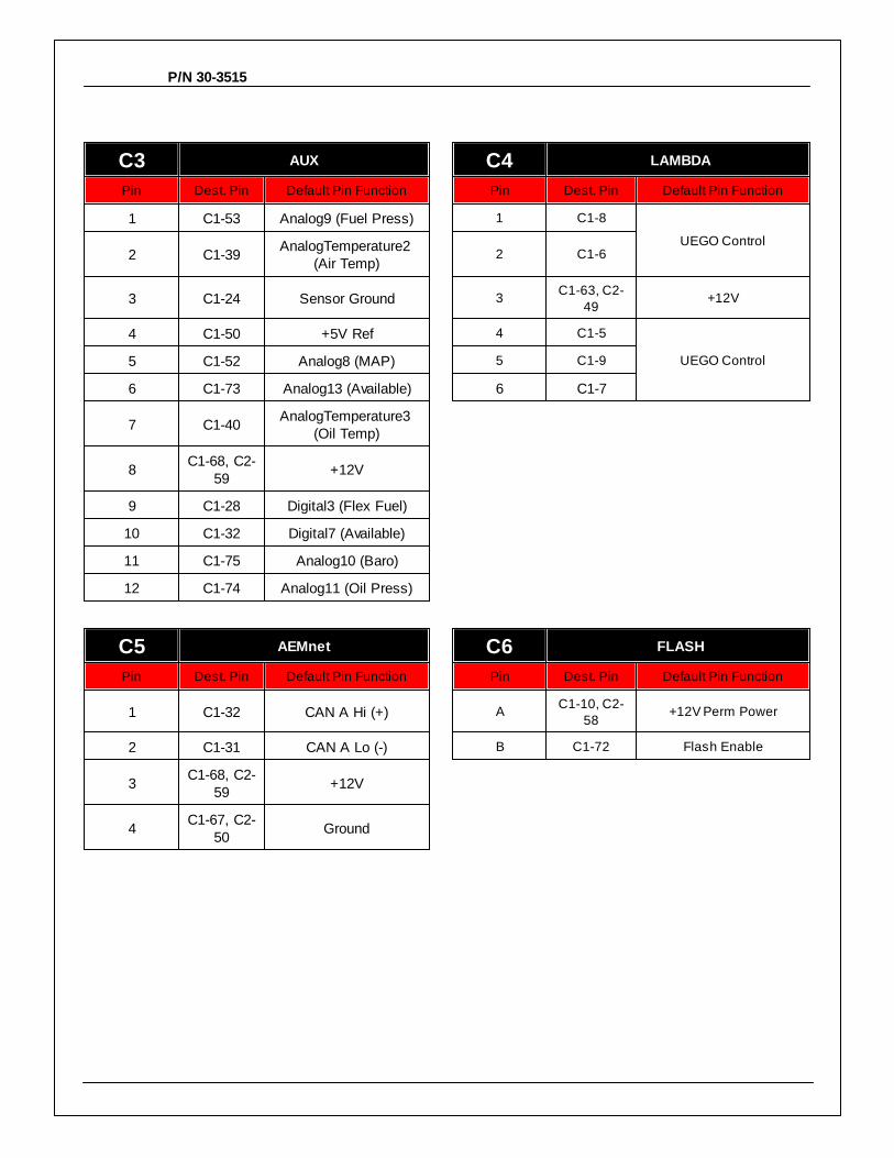
C3 AUX C4 LAMBDA
Pin Dest. Pin Default Pin Function Pin Dest. Pin Default Pin Function
1 C1-53 Analog9 (Fuel Press) 1 C1-8
UEGO Control2 C1-39
AnalogTemperature2 (Air Temp)
2 C1-6
3 C1-24 Sensor Ground 3C1-63, C2-
49+12V
4 C1-50 +5V Ref 4 C1-5
UEGO Control5 C1-52 Analog8 (MAP) 5 C1-9
6 C1-73 Analog13 (Available) 6 C1-7
7 C1-40AnalogTemperature3
(Oil Temp)
8C1-68, C2-
59+12V
9 C1-28 Digital3 (Flex Fuel)
10 C1-32 Digital7 (Available)
11 C1-75 Analog10 (Baro)
12 C1-74 Analog11 (Oil Press)
C5 AEMnet C6 FLASH
Pin Dest. Pin Default Pin Function Pin Dest. Pin Default Pin Function
1 C1-32 CAN A Hi (+) AC1-10, C2-
58+12V Perm Power
2 C1-31 CAN A Lo (-) B C1-72 Flash Enable
3C1-68, C2-
59+12V
4C1-67, C2-
50Ground

PINOUTS