ae/lzt 123 4618/1 r3a, standards, site grounding and ... · pdf fileae/lzt 123 4618/1 r3a...
TRANSCRIPT

Installation ManualAE/LZT 123 4618/1 R3A
StandardsSite Grounding and Lightning Protection

AE/LZT 123 4618/1 R3A
2
Copyright May 1993-2001, M/A-COM Private Radio Systems, Inc. All rights reserved.
CREDITS:ANDREW ANDREW ANDREW ANDREW is registered of Andrew CorporationArrestor-Port is a registered of ANDREW ANDREW ANDREW ANDREW Corp.
Heliax is a registered of ANDREW ANDREW ANDREW ANDREW Corp.Caldweld is a registered of ERICO
GEM is a registered of ERICOPolyPhaser is a registered of PolyPhaser Corp.
XIT and Lynconite are registered of Lyncole Grounding
NOTICE!Repairs to this equipment should be made only by an authorized service technician or facility designated by the supplier. Anyrepairs, alterations or substitution of recommended parts made by the user to this equipment not approved by the manufac-turer could void the users authority to operate the equipment in addition to the manufacturers warranty.
This manual is published by M/A-COM Private Radio Systems, Inc., without any warranty. Improvements and changes to this manual necessitated bytypographical errors, inaccuracies of current information, or improvements to programs and/or equipment, may be made by M/A-COM Private RadioSystems, Inc., at any time and without notice. Such changes will be incorporated into new editions of this manual. No part of this manual may bereproduced or transmitted in any form or by any means, electronic or mechanical, including photocopying and recording, for any purpose, without theexpress written permission of M/A-COM Private Radio Systems, Inc.
The software contained in this device is copyrighted by M/A-COM Private Radio Systems, Inc. Unpublished rights arereserved under the copyright laws of the United States.
NOTICE!

AE/LZT 123 4618/1 R3A
3
TABLE OF CONTENTS
Page1. OBJECTIVE .......................................................................................................................................... 5
1.1. GROUND THEORY .................................................................................................................... 51.2. SCOPE.......................................................................................................................................... 51.3. GENERAL.................................................................................................................................... 51.4. RESPONSIBILITY ...................................................................................................................... 61.5. PROCESS & DEFINITION.......................................................................................................... 61.6. GROUND SYSTEM COMPONENTS......................................................................................... 81.7. CONDUCTORS ........................................................................................................................... 81.8. CONNECTIONS .......................................................................................................................... 91.9. SURGE SUPPRESSION DEVICES........................................................................................... 10
2. GROUND MEASURING TECHNIQUES .......................................................................................... 102.1 Why Measure Soil Resistivity? .................................................................................................... 102.2. Factors Affecting Soil Resistivity on Ground electrodes. ........................................................... 112.3 Soil Resistivity Measurements ..................................................................................................... 142.4 Grounding System Measurements............................................................................................... 16
3. EXTERNAL GROUNDING SYSTEM ............................................................................................... 173.1. ANTENNA TOWER GROUNDS.............................................................................................. 173.2. EQUIPMENT BUILDINGS....................................................................................................... 183.3. BULKHEAD PANEL................................................................................................................. 183.4. FENCES...................................................................................................................................... 183.5. TRANSMISSION LINES........................................................................................................... 193.6. COAXIAL SUPPRESSOR ......................................................................................................... 193.7. TOWER-TOP PREAMPLIFIERS.............................................................................................. 193.8. TOWER-MOUNTED MICROWAVE AND REPEATER EQUIPMENT................................. 203.9. COMMUNICATIONS EQUIPMENT ROOM INTERNAL GROUNDING............................. 20
4. PLANS AND DOCUMENTATION.................................................................................................... 215. SUMMARY OF EXTERIOR SITE GROUNDING ............................................................................ 41GLOSSARY.............................................................................................................................................. 44GROUND RELATED ABBREVIATIONS AND ACRONYMS............................................................. 46VENDOR AND MANUFACTURER CONTACT INFORMATION ...................................................... 47APPENDIX A MICROFLECT DEVICES .......................................................................................... 50
LIST OF TABLESTable 1 Compatible Metals ...................................................................................................................9Table 2 Dissimilar Metals .....................................................................................................................9Table 3 Resistivity By Soil Type.........................................................................................................11Table 4 - Resistivity by Moisture Content..............................................................................................12Table 5 - Resistivity by Soil Temperature..............................................................................................12Table 6 The Affect of Salt Content on Soil Resistivity .......................................................................13Table 7 - The Affect of Temperature on Soil Resistivity .......................................................................13
LIST OF FIGURESFigure 1 Grounding Conductor Label..................................................................................................... 6Figure 2 Soil Resistivity by Seasonal Variation ................................................................................... 13Figure 3 - Soil Resistivity Measurements Using the Model 4500 ........................................................... 14Figure 4 -Grounding Nomograph ............................................................................................................ 15Figure 5 - Ground Measurement Using the AEMC Model 3730............................................................. 16Figure 6 - 62 Percent Method Ground Measurements ......................................................................... 16

AE/LZT 123 4618/1 R3A
4
TABLE OF CONTENTS
Page
LIST OF FIGURES (continued)Figure 7 - Basics of Site Grounding......................................................................................................... 22Figure 8 - Tower Halo Ground Ring........................................................................................................ 23Figure 9 In-Building Halo Ground Ring............................................................................................... 23Figure 10 - Tower -Top Amplifier & DC Power Insert/Pick-Off Connections........................................ 24Figure 11 - Typical Transmit/Receive Site .............................................................................................. 25Figure 12 - "UFER" Ground.................................................................................................................... 25Figure 13 Counterpoise Ground Diagram................................................................................................ 26Figure 14 - Typical "Exothermic" Welds Made Using the Cadwell Method........................................... 27Figure 15 - Examples of the Tools Used to Make Exothermic Welds ..................................................... 27Figure 16 - Isokeraunic Map.................................................................................................................... 28Figure 17 - Typical Installation Cable Entry Panel(s).............................................................................. 29Figure 18 - The ANDREW Integrated Cable Entry/Grounding System .................................................. 30Figure 19 - Joslyn Model 1265-85........................................................................................................... 31Figure 20 - Ground Attachments in Installation....................................................................................... 32Figure 21 - Ground Attachment Methodology......................................................................................... 32Figure 22 - 66 Punchdown Block ............................................................................................................ 33Figure 23 - Andrew SureGround Kits ...................................................................................................... 34Figure 24 - Installation Instructions for XIT Lyncole L-Shaped (Calsolyte ) Ground System.............. 35Figure 25 - Installation Instructions for Straight Shaft (Calsolyte ) Ground System............................. 36Figure 26 - BURNDY Crimp Connectors................................................................................................ 37Figure 27 Andrew Master Ground Bar (MGB)..................................................................................... 38Figure 28 - ANDREW Gas Tube Surge and Quarter Wave Shorted Stub Surge Arrestors..................... 39Figure 29 - Andrew GPS-KIT12 Antenna Kit.......................................................................................... 40Figure 30 Site Grounding Overview..................................................................................................... 42
APPENDIX A LIST OF FIGURESFigure A-1 3 Leg Tower Grounding Kit ...................................................................................................50Figure A-2 Guyed Tower Grounding Kit.................................................................................................50Figure A-3 Four Leg Tower Grounding Kit.............................................................................................51Figure A-4 Monopole Tower Grounding Kit...........................................................................................51Figure A-5 Cable Entry Port Grounding Kit............................................................................................52Figure A-6 10' Self-Supported W/G Bridge Grounding Kit ....................................................................52Figure A-7 20' Ice Bridge Grounding Kit ................................................................................................53Figure A-8 30' Self-Supported W/G Bridge Grounding Kit ....................................................................53Figure A-9 3 and 4 Leg Tower Grounding Kit ........................................................................................54

AE/LZT 123 4618/1 R3A
5
1. OBJECTIVE
The objective of this document is to provide a standardfor M/A-COM site equipment grounding. The methodsrecommended are essential to protect personnel, minimizecomponent failure, and optimize performance by reducingelectrical noise. Transient voltages introduced into asystem by inadequate site grounding often exceed theoperating parameters of electronic components resulting inhigher equipment-failure rates. Semiconductor devices areespecially susceptible to damage by externally inducedtransient voltages.
1.1. GROUND THEORY
All communications facilities are related to ground orearth ground either by capacitive coupling, accidentalcontact or designed contact. If a conducting path for alightning stroke is provided from the point of contact of thestrike to a suitable ground apparatus or electrode, damageand shock hazards can be diminished.
In theory, a ground rod 1-inch in diameter driven intohomogeneous 1000 ohm per meter (ohm/meter) soil onemeter deep would present only 765 ohms of resistance toground. Driving it another meter into the soil (two meters)would yield 437 ohms. Extending the depth to three meterswould yield about 309 ohms.
Using three interconnected ground rods that are eachone-meter long, driven into the same soil area one meterdeep and one meter apart, ground resistance becomes 230ohms. Burying the interconnecting wire below the soilsurface further reduces the ground resistance to less than200 ohms.
Lower ground resistance is, therefore, more rapidlyachieved by installing multiple, interconnected ground rods.
All conductors and connections have some associatedresistance, but the inductive reactance is normally muchlarger. All grounding and bonding conductors must have lowinductance interconnections to minimize the inductivevoltage transients. The impedance of a conductor is themathematical correlation of the resistance and the inductivereactance associated with that conductor. This documentrefers to low resistance, low inductance connections as lowimpedance connections.
The M/A-COM site installation should have less than(below) five (5) ohms resistance between any connectedpoint on the ground bus and earth ground. The exception tothis requirement is noted in Section 2.1.4. AntennaStructures On Tall Buildings.
1.2. SCOPE
This standard has been prepared to address both safetyand equipment damage prevention issues. The grounding,bonding, and shielding procedures described are intendedprovide low impedance designed contact between thecommunications facility and earth ground
This document is to be used as a guide for the designand installation of protective bonding and grounding of allM/A-COM private radio systems and dispatch sites.
1.3. GENERAL
The purpose of an effective ground system is to:
• Protect personnel by reducing the possibility ofelectrical shock.
• Provide a non-destructive, low impedance path toground for lightning strikes and currents.
• Provide a low impedance path to ground for cableshields and other metal encased RF handlingdevices (antennae etc.).
• Protect wiring and other electrical componentsfrom damage.
• Reduce radio frequency noise and suppressdamaging AC power service spikes.
• Maintain proper performance of the antennasystem.
• Control fast-rising electrical surges, which producehigh voltage differences between the ends of singleconductors such as heavy copper wires and bars.
• Equalize surge potentials by controlled bonding ofM/A-COM Communications site ground elements.
These elements include the following:a) Non Isolated Ground Zone (IGZ) equipment
grounds.b) Surge Producersc) Surge Absorbersd) IGZ Grounds
• Reduce voltage differences and control surgecurrents.
The prime source of danger and damage to equipment islightning currents that are often conducted to theequipment through coaxial transmission lines.

AE/LZT 123 4618/1 R3A
6
One of the best ways to reduce the chance of damagefrom lightning is to provide a low impedance path to groundfor lightning currents to prevent them from flowing throughthe equipment.
The isokeraunic map shown in Figure 16 on page 28shows the mean annual number of days with thunderstormsin different regions of the United States.
The region with the highest frequency iscentered around south and central Florida.
NOTE
Another source of surge ingress is through thebuildings electrical utility service. Utility service surgesmay be controlled by installing an AC MOV and AvalancheSurge Arrestor on the incoming power lines. Surgeprotection downstream of the breaker panel may be added ifadditional protection is required. All M/A-COMtransmitting equipment is equipped with internalavalanche and MOV protection.
1.4. RESPONSIBILITY
There are references to ground rods and groundconnections throughout this document. In all cases theremust be only one ground system at each site, building, room,or communications shelter. ALL GROUNDS MUST BETIED TOGETHER (see Figure 8 on page 23, & Figure 30on page 42).
There should be no separately maintained groundrods or ground systems associated with thecommunications shelter, site, building, or equipmentroom. Adherence to these requirements is the standard forM/A-COM Private Radio Systems communicationsfacilities.
1.4.1. Minimum Requirements
The purpose of this specification is to establishminimum requirements for a grounding system that willprovide protection for personnel and equipment. AnyNational Electrical Code or local building grounding-related codes which conflict with items specified within thisdocument may take precedence.
Protective measures intended to prevent equipmentdamage and personnel hazards caused by lightning willincorporate system grounding and bonding using good RFpractices. All conductors and connections have someassociated resistance, but the inductive reactance is normallymuch larger. All grounding and bonding conductors must
have low inductance interconnections to minimize theinductive voltage transients. The minimum bondingconductor size shall be a No. 6 AWG.
Grounding and cabinet bonding conductors should notbe placed in ferrous metallic conduit. If it is necessary toplace bonding conductors in ferrous metallic conduit thatexceeds 1 meter (3 ft) in length, the conductors must bebonded to each end of the conduit with a No. 6 AWG(minimum) conductor.
1.4.2. Labels, Color-Coding, and Marking:
Each telecommunications grounding conductor must belabeled. Labels must be located on conductors as close aspossible to their point of termination to allow ease of accessto read the label. Labels must be non-metallic and includethe information depicted in Figure 1 below.
WARNINGIF THIS CONNECTOR OR CABLE IS LOOSE ORMUST BE REMOVED PLEASE FIRST CALL ORCONTACT THE TELECOMMUNICATlONSMANAGER
Figure 1 Grounding Conductor LabelEach telecommunications grounding conductor must be
marked appropriately by a distinctive green color. Thisincludes all grounding conductors for telecommunicationsequipment as well as grounding to the AC service equipment(AC power).
The bonding conductor for telecommunications must bondthe Telecommunications Main Grounding Busbar (TMGB)to the service equipment (power) ground.
1.5. PROCESS & DEFINITION
All elements of the ground system, and conductingelements in near proximity to the system must be connectedand bonded together. This maintains any and all parts of theradio site at the same ground integrity, as related to trueearth ground (see Figure 9 on page 23 & Figure 11 on page25).
1.5.1. General grounding
Ground currents can circulate and produce voltagedrops within a cabinet, rack, or sub-system producing asource of RF interference. Although they may be of smallmagnitude, they can still cause the signal-to- noise ratio tobecome objectionable. The recommended grounding systemis called The Single Point Ground system. In this

AE/LZT 123 4618/1 R3A
7
document, all system equipment grounds are referred to asingle point. This point is also connected to the site orbuilding ground.
Solid-state equipment, such as that found at anycommunications site, is sensitive to transient voltages andnoise that may enter the ground system. A single pointground is required to isolate the communications equipmentfrom the building, steel framework, superstructure, etc.,except at the Master Ground Bar (MGB). The MGB is theonly point where any other equipment grounds can come incontact with the communications site equipment grounds. Inaddition to the site ground connection, the MGB willinclude:
• Central site ground.• AC equipment ground (green wire).• Frame grounds.• DC Power Plant grounds.
It is important to establish and maintain the single pointground concept. All equipment racks, cabinets, powerframes, and power distribution units must be isolated fromthe building steel, ducts, pipes, etc., to insure that noextraneous currents will flow in the M/A-COM equipmentcabinets, racks, or related hardware. Their grounds must beconnected only to the single ground reference point at theMGB. All grounds must be tight (bonded) and all MGBleads must be as short as possible
1.5.2. DC power plant ground
The main DC power plant ground must be run from thedischarge ground bar to the MGB for single floor buildings,or the Floor Ground Window (FGW) on each floor ofmulti-floor buildings. In small offices with no horizontal orvertical grounding arrangement this lead is generally 2/0(00), or larger, wire.
1.5.3. Entrance cable grounding & bonding
The sheath of each telephone cable entering thebuilding through underground or aerial ducts must bebonded to the ground system. If the MGB is close to thecable entrance, the cable sheaths should be bonded to thisground bar by means of a #2 insulated, stranded, copperwire. If the MGB is not nearby, or is in another part of thebuilding, and a cable vault is provided, a Cable VaultGround Bar (CVGB) must be located in the cable vault. Thecable sheaths are then bonded to this bar by means of a #2(or larger) insulated, stranded copper wire. The CVGB isthen bonded to the MGB with a 2/0 AWG insulated cable.
All grounding and bonding conductors must have lowinductance interconnections to minimize inductive voltage
transients. The minimum bonding conductor size is No. 6AWG.
Grounding and cabinet bonding conductors should notbe placed in ferrous metallic conduit. If it is necessary toplace bonding conductors in ferrous metallic conduit thatexceeds 1 meter (3 ft) in length, the conductors must bebonded to each end of the conduit with a No. 6 AWG(minimum) conductor.
Any lightning arrestor not attached directly to the cableentry port is to be connected to a ground bar (preferably theMGB) by short lengths of insulated No. 6 AWG (or larger)wire or flexible copper straps. If this ground bar is asecondary ground bar, it must be connected to the MGBusing a No. 2 AWG, (minimum) insulated cable.
1.5.4. Equipment frame grounds
The framework of all equipment racks must begrounded! Grounding is as important in small M/A-COMPrivate Radio Systems as it is in complex, multi-site, andmulti-channel systems. The practices may vary from systemto system, however the basic concept within this documentmust be followed.
1.5.5. Coax and Transmission Line Grounding
Each coaxial line used At M/A-COM communicationssites and antenna tower locations must have a minimum ofthree lightning protection grounding kits attached. Agrounding kit should be installed at 100-foot intervalswherever vertical cable runs on towers exceed 200 feet, (seeFigure 23, page 34). This process is illustrated in moredetail in Figure 7 (page 22), specifically points 1, 2, & 3.
Each coaxial cable must have an Andrew Gas DischargeTube (GDT) or equivalent lightning arrestor near the cableentrance to the communications shelter or room. Quarterwave stubs or Gas Discharge Tubes (QWS or GDT) are thepreferred types and are believed to be the best lightningarrestors presently available (see photo and illustrations inFigure 28 on page 39).
Grounding kits must be terminated at the master groundbar. All connections to the master ground bar must be cleanand free of any oxidation to insure a low impedanceconnection. The lightning arrestors are effective in limitingthe amount of lightning energy that can be transferred to theequipment through the inner conductor of the coax ortransmission line.

AE/LZT 123 4618/1 R3A
8
1.5.2. Equipment Grounding
Each equipment rack, equipment cabinet, or equipmentshelf must be grounded to a site ground through the in-building Halo (see glossary) ground. Equipmentenclosures used inside of communications shelters must beattached to this system "Halo" ground in the same manner.
1.6. GROUND SYSTEM COMPONENTS
A complete grounding system for the antenna, towers,and buildings must be provided. This includes internal andexternal grounding systems for equipment in thecommunications buildings, the antenna towers and guys,transmission lines, telephone lines, DC power plants, ACpower lines, and the communications facility.
No grounds may be run inside metal conduits becausemetal conduits increase the surge impedance of thegrounding cables. The grounds that make up the inside Haloground must be number 2 AWG or larger copper wirecovered with an approved non-conductive green plasticcovering.
If non-insulated wire is used for the inside halo(faraday) ground ring, a non-conductive insulating sleevemust cover the wire where it passes any metallic conduitsor metal objects. Halo ground wires attached to exit groundwires must be solid, tinned, bare copper (number 2 AWG orlarger).
1.6.1. Ground Rods
M/A-COM ground system ground rods must be barecopper-clad steel, 5/8 inch in diameter, and a minimum of 8feet in length. Multiple, interconnected, copper-clad steelground rods are normally provided (see Figure 30, page 42).
The minimum distance between ground rods must be 16feet (where space permits) to maintain the integrity of theground system. Exothermic bond/weld (Cadweld)connections (Figure 14, page 27) must be made at all groundrod connections. For detailed information, contactERICO/CadWeld at (800) 677-9089.
1.6.2 Chemical Ground Rods
A Chemical Ground Rod is an electrolytic ground rod(usually a 2 inch copper tube, see Figure 24 on page 35)designed to provide a low-impedance and low-resistanceground. Moisture is drawn into the rod by changes inatmospheric pressure. Through a process of continuosleaching, small amounts of an environmentally safecompound are released into the soil. This compound
enhances the earth ground. The solution slowly leaches intothe surrounding earth, creating an ion root that has ametallic base (see Figure 24 on page 33 and Figure 25 onpage 36). This process continually conditions the soil,reducing soil resistance, enhancing the ground systemeffectiveness over time. The chemical rods provide lowerresistance grounds than conventional solid, copper clad rodsin virtually any soil.
The Lyncole XIT chemical ground rod is constructed ofhard-drawn copper tubing. The rod is built to last up to 30years in certain soils and climates. A heavy 2/0 or 4/0"pigtail" should be attached to the chemical ground rodusing the Cadweld process (see Figure 14, and Figure 15on page 27) to provide for easy connection to other parts ofthe ground system. The pigtail is Cadwelded directly to thecopper tube to provide the best possible physical andelectrical bond.
Chemical ground rods can often provide a more reliableground than using multiple copper clad ground rods. This isespecially good where soil is shallow and the rock baseprevents deep driving of copper clad ground rods
1.6.3 Ground Enhancing Backfill
A clay-salts compound called Bentonite may be usedas backfill to provide additional ground enhancement.
Chemical ground rods used with a galvanic backfill,such as bentonite, provide the best solution to a difficultgrounding problem. Bentonite helps the soil to retain moremoisture, which tends to increase soil conductivity. Addingthe bentonite as backfill enhances the electrical contact withthe earth.
1.7. CONDUCTORS
Conductors that are used below ground for connectingground rods must be:
a) Stranded bare copper wire, number 2 AWG orlarger.
OR
b) Solid 18 AWG (minimum) bare copper strap, aminimum of two inches wide.
Conductors used above ground for interconnectingground rings, Halo's, equipment racks and cabinets, andother metal items must be:
a) Solid or stranded copper wire number 6 AWG orlarger.
ORb) Solid 16 AWG (minimum) copper strap, a
minimum of two inches wide.

AE/LZT 123 4618/1 R3A
9
1.8. CONNECTIONS
All ground connections must be made using minimumlength conductors with straight vertical (or horizontal) runs,if possible. Conductor bends, when required, must begreater than 12-inch radius. Connecting conductors mustalways transition in the direction of current flow or towardearth ground, and approach the main ground at an angle ofroughly 45 degrees.
Connections of dissimilar metals can cause deteriorationof grounding surfaces. Table 1 contains a list of metalsdivided into groups. Using only similar metals (from thesame group) prevents ground contact surface deterioration.
Table 1 Compatible MetalsGroup A Group B Group C Group D
Magnesium Tin Stainless Steel Copper
Aluminum Lead Nickel Silver
Zinc Steel Iron
Surface contact of dissimilar metals may be used withthe following stipulations:
Table 2 Dissimilar MetalsCONTACTSURFACES
INSIDE OUTSIDE(Weather Exposed)
Within samegroup
OK OK
Adjacent groups OK* Weatherproof coatingmust be applied afterdirect metal-to- metalcontact.*
∗ No liquid should be allowed to come into contactwith surface gaps or metal contacts from adjacentgroups.
1.8.1. Exothermic or Permanent GroundingConnections
Exothermic power and grounding connections must bemade with a pre-engineered system using a controlledexothermic chemical reaction. Cadweld (see ExothermicWeld in the Glossary) is a bonding process that provides ametallic bridge connection that exhibits virtually noresistance and its conductivity approximates that of the
associated conductors. Exothermic connections offer thefollowing advantages over other types of connections:
• The connection permanently welds every strand ofthe conductor.
• The connection is made with portable equipmentthat requires no outside source of heat or power.
• Loosening or corrosion of the current path cannotoccur.
• The connection is able to withstand repeated highcurrent surges [faults] without damage to theconnection or the conductor.
• No special skill and minimum training is required.
• Installation time is the same as with other kinds ofconnections.
1.8.2. Permanent Grounding ConnectionSpecifications
All grounding connections (conductor-to-conductor,conductor-to-ground rod and conductor-to-structure or fencepost) of #6 AWG and larger copper conductors must bepermanently exothermically welded. Contact ERICO/CadWeld (800-677-9089) for more detailed information.
Copper grounding conductors spliced with exothermicconnections are considered a continuous conductor, as statedin NEC 250-81 Exception No. 1 and 250-91 Exception No.3.
All connections must meet the applicable requirementsof IEEE Std 80-1986. For this reason, Cadweld® exothermicconnections are suggested as they are approved in NEC 250-81, -91, -113, and -115.
Welding material for copper-to-copper and copper-to-steel connections must contain copper oxide, aluminum andnot less than 3 percent tin as a wetting agent. Startingmaterial [if used] must consist of aluminum and copperoxides. It must not contain phosphorous or any caustic, toxicor explosive substance.
All exothermic connections made to the ground system,including test leads, must be made with an exothermicwelding process specifically designed to restrict heat energytransfer to surrounding objects
Weld metal must be controlled at the point ofmanufacture and subjected to rigid quality control inspectionprocedures.

AE/LZT 123 4618/1 R3A
10
1.8.3. Below Ground
Connections made to ground rods, or to conductorsbelow ground must be made using an exothermic processsuch as Cadweld or equivalent. This attachment procedureinsures firm, electrically conductive, mechanically rigid, andmaintenance free connections. Connecting andinterconnecting conductors must be placed at the same depthas the tops of the ground rods.
Contact ERICO/CadWeld at (800) 677-9089 fordetailed information.
1.8.4. Doping Of Ground Systems
When unable to achieve grounds below 10 ohms, somedoping of the earth may be necessary. One of the bestmethods used today to increase the conductivity (reduceresistance) of the ground is another Cadweld product calledGEM®. (ERICO® Ground Enhancement Material) IfGEM is unavailable bentonite may be used.
ERICO GEM is a superior, conductive material thatimproves grounding effectiveness regardless of soilcondition. It is an ideal material to use in areas of poorconductivity soil, such as rocky ground, mountain tops andsandy soil. GEM is added around a ground rod in anaugured hole or around a conductor in a trench. TheGEM material increases the effective diameter of the rod orconductor.
ERICO GEM has a constant cured resistivity of 12ohm/cm or less. It must set up to a hard, permanent materialand does not decompose or dissolve over time. It does notrequire any maintenance after installation. It does not rely onthe continuous presence of water, nor does it add salts to theearth that could contaminate the ground water. The materialis packaged in 25 pound bags and may be added dry or pre-mixed in a slurry, like cement.
1.8.5. Above Ground
Connections made above ground, in areas exposed toweather, must use Cadweld (or a similar exothermicprocess), where possible. If environmental conditionsprevent the use of the Cadweld process, an appropriatepressure-type connection may be used.
Where above ground pressure type connections areemployed, stranded wire must be used. Connections madeabove ground must be made with appropriate passivation ofthe mating surfaces, or using special transition clamps suchas a PolyPhaser Model J-1, J-2, or equivalent.
Stranded conductors must be connected to equipmentracks using lugs or pressure clamps consistent with the wiresize and grounding surface of the equipment beinggrounded.
Connections to tower guy wires must be pressureconnections.
1.9. SURGE SUPPRESSION DEVICES
Substitutions for the specific recommendedmanufacturer surge suppression device types referred to inthis document may be made as long at the substitute is of thesame quality and performs the same function. Considerationmust be given to the voltage clamping level, response time,and energy rating for the intended application. Power linesurge suppressors similar to the Joslyn 1265-85 (see Figure19, page 31) should be included at the service entrancebreaker panel
1.9.1. The Following Practices Are to be Avoided!
a) Never run ground wires through metal conduit.When the ground must be carried through a metalconduit, the ground wire must be bonded at eachend of the conduit.
NOTE: PVC conduit is preferred as a single run groundconduit where the ground wire exits the communicationsroom or shelter (see note inFigure 7, page 22).
b) Never rely on the third wire (green wire) on ACpower services for lightning ground.
A neutral conductor must never be grounded again after it has beengrounded at the service entrance. This is to avoid 60 Hz return currentpassing through conduit, framework, etc., thereby causing noise insusceptible electronic circuits.
2. GROUND MEASURINGTECHNIQUES
2.1 WHY MEASURE SOIL RESISTIVITY?Soil resistivity measurements have a threefold purpose.
First, such data are used to make sub-surface geophysicalsurveys as an aid in identifying ore locations, depth tobedrock and other geological phenomena. Second, resistivityhas a direct impact on the degree of corrosion inunderground pipelines. A decrease in resistivity correspondsto an increase in corrosion activity and, therefore, dictatesthe protective treatment required. Third, soil resistivitydirectly affects the design of a grounding system, and it is tothat task that this discussion is directed. When designing anextensive grounding system, it is advisable to locate the area

AE/LZT 123 4618/1 R3A
11
of lowest soil resistivity in order to achieve the mosteconomical grounding installation.
Ground measurements made on a new site prior toground-breaking or during site survey and site prep, may bemade using the AEMC model 4600 or 4610 to determinethe soil resistance. This measurement will enable the M/A-COM engineer to determine the type of ground system thatwill be employed at the site; e.g. chemical, XIT, orconventional ground(s). The Vendor for AEMC Measurementdevices is Lyncole XIT Grounding; 3547 Voyager St., Torrance, CA90503. Phone (800) 962.2610.
Ground system measurements at an existingcommunications site with an existing ground system may bemade using an instrument similar to the AEMC Model3710. Use the instructions provided with the AEMC model3710 or 3730 Ground Test Instrument.
2.2. FACTORS AFFECTING SOILRESISTIVITY ON GROUNDELECTRODES.
Soil resistivity is the key factor that determines theresistance of a grounding electrode, and to what depth itmust be driven to obtain low ground resistance. Theresistivity of the soil varies widely throughout the world andchanges seasonally. Soil resistivity is determined largely byits content of electrolytes, which consist of moisture,minerals and dissolved salts. A dry soil has high resistivity ifit contains no soluble salts (Table 1). Two samples of soil,when thoroughly dried, may in fact become very goodinsulators having a resistivity in excess of 109ohm-centimeters. The resistivity of the soil sample changes quiterapidly until approximately 20% or greater moisture contentis reached (Table 4).
Table 3 Resistivity By Soil TypeSOIL RESISTIVITY (Ohm-cm)
[Range]
Surface soils, loam, etc. 100 - 5,000
Clay 200 - 10,000
Sand and gravel 5,000 - 100,000
Surface limestone 10,000 - 1,000,000
Limestones 500 - 400,000
Shales 500 - 10,000
Sandstone 2,000 - 200,000
Granites, basalts, etc 100,000
Decomposed gneisses 5,000 - 50,000
Slates, etc 1,000 - 10,000
AE/LZT 123 4618/1 R3A
12
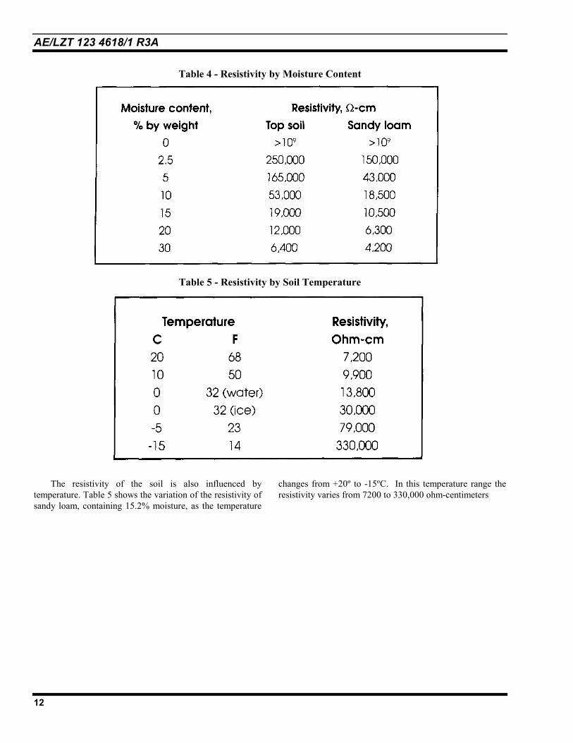
Table 4 - Resistivity by Moisture Content
Table 5 - Resistivity by Soil Temperature
The resistivity of the soil is also influenced bytemperature. Table 5 shows the variation of the resistivity ofsandy loam, containing 15.2% moisture, as the temperature
changes from +20º to -15ºC. In this temperature range theresistivity varies from 7200 to 330,000 ohm-centimeters

AE/LZT 123 4618/1 R3A
13
.Figure 2 Soil Resistivity by Seasonal Variation
(With an electrode of ¾ inch pipe in rocky clay soil. Depth of the electrode in earth is 3 ft for curve 1, and 10 ft for curve 2.)
Soil resistivity is directly related to moisture contentand temperature. Therefore it is reasonable to assume thatthe resistance of any grounding system will vary throughoutthe different seasons of the year. Such variations are shownin Figure 2.
Both temperature and moisture content become morestable at greater distances below the surface of the earth.The ground rod should be driven a considerable distancebelow the surface of the earth for the grounding system to bemost effective at all times. Best results are obtained if theground rod reaches the water table.
Table 6 The Affect of Salt Content on Soil Resistivity
Table 7 - The Affect of Temperature on Soil Resistivity
Table 6 and Table 7 illustrate the effects of salt content and temperature on similar types of soil.

AE/LZT 123 4618/1 R3A
14
2.3 SOIL RESISTIVITY MEASUREMENTSThe optimum soil resistivity of a sizable tract of land may be determined using the information given in through Table 7.
Assuming that the objective is low resistivity, preference should be given to areas containing moist loam as opposed to dry,sandy areas. Consideration must also be given to the depth at which resistivity is required.
Figure 3 - Soil Resistivity Measurements Using the Model 4500Referring to Figure 3, A= the distance between the measurement electrodes (in centimeters), and
B= measurement electrode depth (in centimeters).Practical soil resistivity measurements can be made using the AEMC Model 4500, as shown in Figure 3, using thefollowing formula. Choose the target depth of the ground rod.
For the purpose of this measurement:Set A= the target depth of the ground rod
B= A ÷ 20AR•= πρ 2
Where ρ = Soil Resistivity (ohm-cm) Ω/cmA= Model 4500 Measurement Electrode Spacing (cm)R= Model 4500 reading (Ω)(B= Model 4500 Measurement Electrode Depth (cm))
This formula represents the average resistivity of the ground at a depth equivalent to the distance "A" between two electrodes.Example:
The area investigated has been narrowed down to a plot of ground approximately 75 square feet (7 m2). Assume that youneed to determine the resistivity at a depth of 15 feet (450 cm). The distance "A" between the electrodes must then beequivalent to the depth at which average resistivity is to be determined (15 ft, or 450 cm). Using the Wenner formula givenabove, the measurement electrode depth must be 1/20th of the electrode spacing or 8-7/8" (22.5 cm). The AEMC Model4500 reads 15Ω resistance between electrodes.
R (model 4500 reading) = 15ΩA (distance between measurement electrodes) = 450 cmρ (resistivity) = AR•π2
1545028.6 ••=ρ = 42,390 Ω/cmThe soil resistivity at a depth of 15 feet is, therefore, 42,390 Ω/cm for the chosen plot of ground.

AE/LZT 123 4618/1 R3A
15
Figure 4 -Grounding Nomograph
The Grounding Nomograph in Figure 4 is used to further improve the grounding system by relating practical constraintssuch as the ground rod diameter and length to the calculated soil resistivity to optimize the total ground rod resistance.

AE/LZT 123 4618/1 R3A
16
2.4 GROUNDING SYSTEM MEASUREMENTS
Figure 5 - Ground Measurement Using the AEMC Model 3730
Figure 6 - 62 Percent Method Ground MeasurementsFigure 6 shows ground measurements made using the AEMC 4610, and AEMC 4500
(Commonly referred to as the62 percent method.
The ground rod or grounding system measured must be disconnected from all equipment and structures for accurate results.
NOTE: If the ground rod to be tested is attached to an active (live) power distribution panel, USE EXTREME CAUTIONWHEN REMOVING THE LINK TO ISOLATE THE GROUND ROD(s) UNDER TEST. A voltage potential differencebetween the ground lead and the AC power neutral line could present hazardous currents on the system ground (i.e. EMFand currents between the local ground and the utility grid ground). Injury could result when the ground system is isolated.Suggestion: SWITCH POWER OFF: Open main power disconnect before removing (opening) ground lead
connection.

AE/LZT 123 4618/1 R3A
17
3. EXTERNAL GROUNDINGSYSTEM
External grounding rings installed by M/A-COM orapproved contractors must individually encircle theantenna tower, the building, or equipment shelter.
Ground rods for the tower and building must beinstalled so that the tops of the rods are a minimum of 24inches below the soil surface. The ground rods for towerground must be installed so that the bottom ends of therods are deeper than the lowest part of the tower footing.
Each ground ring, including the tower, building,fence, or other ground ring must be interconnected with aminimum of two number 2 AWG (or larger) strandedcopper wires. Where Andrew (or similar) cable entrypanels are employed, copper straps or parallel 2/0 copperwire must be connected to the main ground to form a verylow impedance path to earth ground. Connections to theground, or ground ring must be made using an exothermicprocess (Cadweld, or equivalent), wherever possible.Contact ERICO/CadWeld at (800) 677-9089 fordetailed information. (See Exothermic Weld in the)
3.1. ANTENNA TOWER GROUNDS
3.1.1. Monopole Towers
The ground system for monopole masts must consistof a minimum of three ground rods, connected togetherper paragraph 1.7, Conductors Below Ground.
The mast connection to the ground system must bemade with stranded, number 2 AWG (or larger) wire.Connections to the mast must be in accordance with themanufacturer's instructions or use the exothermic Cadweldmethod. The connections must be short and direct, with nosharp bends (see Figure 9, page 23).
3.1.2. Wooden Antenna Poles
The proper grounding system for wooden antennapoles consists of a minimum of two ground rodsconnected together and installed per paragraph 1.7,Conductors Below Ground.
Connections to the antenna or antenna mast at the topof the pole, must be made according to the manufacturersrecommendations. A number 2 AWG (or larger) strandedcopper ground wire must be extended down along thepole, away from any other conductors (to avoid possibleflashover).
3.1.3. Self Supporting Lattice Towers
The self-supporting lattice tower grounding systemconsists of a ground rod at each tower leg. If necessary,additional ground rods may be used to decrease groundresistance, or to reduce the distance between rods. Groundrods must be connected together per paragraph 1.7,Conductors Below Ground. Each tower leg must beconnected to the grounding system with number 2 AWG(or larger) stranded wire. Connections to the tower legmust be short and direct, with no sharp bends.
3.1.4. Guyed Lattice Towers
The guyed lattice tower grounding system consists ofthree ground rods at the tower base. These ground rodsmust be connected together per paragraph 1.7,Conductors: Below Ground. The ground conductors usedto connect the grounding system must be number 2 AWG(or larger) stranded wire. Connections to the tower mustbe short and direct, with no sharp bends.
A ground rod must also be installed at each guyanchor point, approximately one foot from the anchorfooting (see Figure 12 on page 25, Figure 23 on page 34and Figure A-2 on page 50). The top of the ground rodmust be a minimum of 24 inches below the soil surface,where possible. The bottom of the ground rod must extendbelow the lowest point of the anchor footing.
Number 2 AWG stranded copper wire must be usedto connect each of the guy wires to the ground rod at theguy anchor. Each ground rod must be connected to thetower "ground ring" below ground, using number 2stranded copper wire.
3.1.5. Antenna Support Structures On Buildings
Radio antenna installations on the tops of buildingsmust have the tower, down conductors, transmission lineshields, and other conducting objects within 6 feet of thetower or antenna base securely bonded together perparagraph 1.7, Conductors Above Ground and 1.8-1.8.5,Connections: Above Ground.
The common bond point at the top of steel-framestructures may, where possible, be bonded to buildingsteel with number 2 AWG (or larger) copper wire. Thetower may also be bonded at the roof level to a large,metal, earth grounded, cold water pipe (if available).
The common bond point at the top of reinforcedconcrete buildings must be connected to ground usingnumber 2 AWG (or larger) stranded copper conductors.These may be bonded to the earth grounded cold water
AE/LZT 123 4618/1 R3A
18
main in the basement of the building or bonded to thebuilding ground system. The tower should also be bondedat roof level to a large, metal, earth grounded, cold waterpipe (If available).
Guy wires associated with building-top towers mustbe grounded at their anchor points to a common bondpoint in the same manner as for grounding terrestrialtowers (see Figure A-2, page 50). A dissimilar metalinterconnect device must be used between the guy wireand the ground wire. There must be a three inch(minimum) "play" loop between guy-to-guy groundconnections whenever the ground wires from multipleguys are daisy-chained together.
The ground resistance of tall building installationsshould be less than ten (10) ohms between any equipment-connected ground bus and earth ground.
An instrument similar to the AEMC Model 3700 HDmay be used to make ground resistance measurements.The measurements must be made according to theinstructions provided with the AEMC 3700 HD GroundTest Instrument. For vendor information on AEMC measurementdevices contact Lyncole XIT Grounding; 3547 Voyager St., Torrance,CA 90503. Phone (800) 962.2610.
3.2. EQUIPMENT BUILDINGS
The external grounding system used around theexterior of the communications shelter or building iscalled a Halo Ground. This ground system consists of aground rod at each corner of the building. Additionalground rods must be added, if necessary, to restrict thedistance between rods to less than 10 feet.
A ground rod must be installed directly below thecoax transmission line entrance to the building. Groundrods are spaced approximately 2 feet out from theperimeter of the building.
3.3. BULKHEAD PANEL
A weatherproof metal bulkhead panel must beinstalled on the building equipment wall (see Figure 17 onpage 29 & Figure 18 on page 30). The panel must becomparable to the Andrew Type APORT-13-4 or thePolyPhaser Earthed Entrance Panel (PEEP) models.The size of the panel is determined by the number andsize of the transmission lines interconnecting through it(see Figure 18, page 30 for dimensions). Use appropriatecable boots to weatherproof the connections.
The external panel must include a ground bar fortransmission line shield to ground connections and
connections to the external ground system (see Figure 7on page 22 & Figure 9 on page 23). The ground bar mustbe made to avoid dissimilar metal connections as stated inTable 1, page 9 (also see Figure 27 on page 38, andparagraph 1.7, Conductors Above Ground.). The groundbar shown in Figure 27 must be connected to the buildingexternal ground system by number 2 AWG wire. Twoconductors or two copper straps may be used to form alow impedance path to the system ground).
An internal sub panel similar to the Andrew Arrestor-Port (see Figure 18, page 30), bolted directly to thebulkhead panel with multiple bolts may be used to mountthe transmission line surge suppresser specified inparagraph 3.6, Coaxial Suppressor. The sub-panel mustbe securely fastened with a low resistance, low inductancepath to the bulkhead panel (stranded No. 2 AWG orlarger).
The Andrew Arrestor Port II grounding system has13 openings for Type N or 7/16 DIN bulkhead mountsurge arrestors and four 4" holes for standard waveguideboots. Integrated universal grounding bars provide eighttwo-hole grounding leads on each side of the bulkheadgrounding plate.
3.4. FENCES
Metal fences within 6 feet of any ground ring or anygrounded object must be grounded at twenty-footintervals, or at a minimum of each corner post and at eachgate metal support post (wherever possible). This is toprovide additional shock hazard protection from lightning.Any metal fence greater than 8 feet from the ground ringshould be grounded at fifty (50) foot intervals along itslength (see Figure 30, page 42).
A copper-clad steel ground rod, 8 feet long(minimum), and 5/8 inch diameter must be driven into theground within one foot of the fence, near a fixed gatehinge post where appropriate. The top of the ground rodmust be a minimum of 24 inches below the ground surface(see Figure 11 & Figure 12 on page 25 for similarconnections), or at the same level as the external groundring to which it will be connected. Additional groundrods may be installed for each 50 feet of fence, at equalspacing outside 6 feet of the ground system butsurrounding the facility.
Each ground rod must be connected underground bythe most direct path to the nearest tower or buildingground ring using a stranded copper wire, number 2 AWGor larger (see Figure 11 on page 25 & Figure 30 on page42).

AE/LZT 123 4618/1 R3A
19
Above ground connections must be made using anexothermic weld or a pressure clamp near the bottom ofthe metal post. Connections made below ground must useexothermic welds (Cadweld). Tinned copper ground strap(braid) must be used to connect metal fence gate(s) to themain post. Use pressure clamps with these connections.
3.4.1. Nearby Metal Objects
The following components must be connected to theexternal grounding system using a number 2 AWG (orlarger) stranded copper wire.
a) The transmission line entry window into thebuilding. This is the entry point into theequipment area. All transmission lines aregrounded to this window, and extra care must beused to insure a very low inductance path toground.
b) Ice shielding and exterior cable trays between thetower and the building.
c) The emergency generator and any platform orbase used by the generator.
d) Fuel tanks, above or below ground.e) Any other large metal or conductive objects
within 6 feet of the communications shelter,tower, or the system ground.
f) Any other ground systems provided bytelephone, or electric utility providers. Localelectric codes should be observed when makingthis attachment.
3.5. TRANSMISSION LINES
This section applies to the antenna and transmissionlines outside the communications shelter or building,where entry is made into the equipment shelter (SeeAppendix A, Figure A-5, page 52). These requirements donot apply to antenna and transmission lines that arecontained entirely within the equipment room orcommunications shelter.
3.5.1. Shield Grounds
The outer conductors of coaxial transmission cablesmust be grounded with an appropriate coaxial cablegrounding kit (see Figure 23, page 34). A grounding kitmust be installed at each of three points on the cable:
1) Immediately outside the cable entrance to theequipment room, shelter, or building. This groundmust be located before the lightning suppressor.
2) At the bottom of the vertical run of the cable, at apoint near and above the bend onto the ice-bridge orsupport trestle. This grounding point must be as nearto the ground as possible.
3) At the top of the vertical run of cable, at thetermination or antenna. This point is grounded orbonded to the tower using the clamp supplied with thegrounding kit.
All three points should be grounded in accordancewith the recommendations provided in the grounding kitinstructions. These instructions are included in groundingkits similar to the Andrew type 204989 or thePolyPhaser Uni-Kit 2.
3.6. COAXIAL SUPPRESSOR
A Poly-Phaser type IS-B50 (or equivalent) lightningsuppressor must be installed at each building orcommunications shelter cable entrance. This suppressormust be bonded to the nearby ground bus plate to removesurge currents from the center inductor of the cable.
3.7. TOWER-TOP PREAMPLIFIERS
M/A-COM will install an impulse suppressor similarto the PolyPhaser IS-DC50LN DC injection typewherever coaxial-transmission-line-DC-voltage-suppliedtower-top amplifiers are used. Certain tower-topamplifiers are already equipped with this type protection(see Figure 10, page 24).
PolyPhaser type IS-GC50LN pick-off surgesuppressors may be installed (according themanufacturers instructions) as an additional protectivemeasure at the input ports of the tower-top amplifiers orpreamplifiers. This protection is in addition to the M/A-COM internal amplifier protective devices. All tower-toppreamplifier chassis must be grounded to the tower.
An added protection device may be required wherecable entry bulkheads are a part of the coaxial cablesbetween the tower top amplifier and the M/A-COMcommunications equipment. The PolyPhaser IS-DC50LNZ pick-off and re-injector (PICKOR) may beused. Figure 10 on page 24 provides illustrated details forthe installation of these devices.
DC ground, shunt-fed antennas should be used asadditional protection for the tower-top preamplifiers,where possible. Cable attachments to the antennas shouldbe kept as short as possible.

AE/LZT 123 4618/1 R3A
20
3.8. TOWER-MOUNTED MICROWAVEAND REPEATER EQUIPMENT
The input and output points of tower top repeaters arethe most important points to protect. Tower, telephone orcontrol lines are often overlooked. Coaxial line protectorsare used at the M/A-COM repeater inputs and outputs,and at the pre-amp front end. Power line protectors mustbe local and single-point grounded at the top of the tower,along with the repeater equipment. The need for powerprotection is doubled for tower top repeater and pre-ampinstallations where 120 or 240 VAC is supplied to the topof the tower.
Microwave equipment operating at frequencies above18 GHz usually have Gunn (microwave diode) downconverters located on the back of the dish, powered byone or two coaxial lines. These lines also handle theuplink and downlink frequencies, as well as AFC(Automatic Frequency Control) error information. ThePolyPhaser IS-MD50LNZ (or equivalent) should be usedat the top and bottom of the tower to properly protect thistype of equipment. The PolyPhaser IS-DC50LNZ isanother type of protection device used in theseapplications and is fully transparent to control voltagesand signals from microwave equipment.
3.9. COMMUNICATIONS EQUIPMENTROOM INTERNAL GROUNDING
A Halo ground should be used inside thecommunications shelter to provide ground connection tothe equipment inside the shelter. The Halo should form a"ring" around equipment racks, cabinets, cable trays, andequipment shelves in such a manner as to enable the useof short length conductors attached from the equipment tothe ground ring (Halo).
The exception to this requirement is when the equipmentroom is located below the soil surface (below ground)level!
The Halo must be made of number 2 AWG strandedcopper wire attached to standoffs (see Figure 9, page 23)at approximately eight (8) feet above the equipment roomfloor.
Four (4) ground risers (minimum) are used wheneverthe perimeter of the room or communications shelter isless than 100 linear feet. A ground riser should be used ateach corner of the perimeter of any room or building (seeFigure 7, page 22), wherever possible. A ground risermust be attached every twenty (20) feet for installationswhere the perimeter of the equipment room exceeds 100
feet. These ground risers are made of number 2 AWGSOLID copper, which exit the room or building thruoghpolyvinyl conduits (see PVC exit Figure 7, page 22).
The main function or purpose of the inside ground ring(Halo) is to form a faraday cage/shield. Actual testsprove that this system captures stray or ingress EMFthat is generated by nearby electrical disturbances(lightning etc.). Many dropped calls have been provento be caused by EMF lines-of-force crossing the fields ofcables carrying RS232 or TTL (logic) signals.
3.9.1. Grounding Equipment Cabinets, Racks, AndShelves
Each equipment cabinet or rack must be equippedwith a ground-bus that is attached to the external systemground through the in-building halo ground. Eachequipment chassis secured in a cabinet or rack must beconnected to the cabinet or rack ground-bus. Thepreferred ground connection points are on the equipmentmounting rails within the cabinets or racks. Paint-cuttinglock-washers must be used where metallic chassis-to-railconnections are made.
Equipment cabinets and enclosures are attached to thesystem ground using number 6 AWG (or larger) strandedcopper wire (see Figure 9 on page 23 & Figure 20 on page32). The length of these connections should be kept asshort as possible to decrease inductance.
The main ground window near the cable entry panelis connected to overhead cable ladders/trays using anumber 2 stranded copper wire. The number six groundwires from each cabinet are attached to the overheadground bus using Burndy HyPressure HyTap,HyTail, or HyLug (or equivalent) crimps (see Figure 26,page 37), and doped with Penetrox® E Oxide Inhibitor(or equivalent). Burndy HyTap is the recommendedlink, distributed by XIT/Lyncole.
3.9.2. CABLE TRAYS
Cable trays must be attached to the internal groundhalo using number 2 AWG (or larger) stranded copperwire. Additional connection must be made between cabletray sections when mechanical connections (lugs, bolts)are made between cable tray sections (see text in Figure 9on page 23). Number 6 AWG (or larger), stranded copperwire must be used to ensure a good electrical groundconnection between tray sections (see Figure 20, page 32).
Grounds between cable trays, equipment cabinets,equipment racks, and AC utility power enclosures must be

AE/LZT 123 4618/1 R3A
21
made using number 2 AWG or larger stranded copperwire.
The Burndy compression system should be used whencompression type connectors are used at an M/A-COMinstalled site or system. This system includes connectorsfor taps, splices, and structural steel terminations. Theseconnectors may only be used in certain M/A-COM siteground applications inside of communications rooms orshelters. These compression connectors are not to beused underground or beneath soil. The Burndy systemconnectors are listed with Underwriters Laboratoriesunder Standard UL467. Most of these connectors havebeen successfully tested according to the requirements ofIEEE Standard 837.
4. PLANS AND DOCUMENTATION
Drawings and Ground reference documentation mustinclude the following items:
a) A grounding and bonding plan.
b) Ground rod specifications.
c) Surge suppression device specifications.
d) Bulkhead panel type specifications.
e) Coaxial cable grounding kit specifications.
All lightning and surge protection measures includedin an M/A-COM Private Radio System are submitted as apart of the overall system specification. This specificationtakes into account the radio installation, equipment to beprotected and local conditions. All requirements coveredin this specification must be met, unless a specific, writtenwaiver is provided by the customer and agreed to by M/A-COM.

AE/LZT 123 4618/1 R3A
22
Figure 7 - Basics of Site GroundingFigure 7 illustrates some of the grounding techniques
described in this document. In addition it depicts how theinside and outside Halo grounds are interconnected. Theinstaller should insure that all wire bends and turns in theHalo ground ring are smooth with no sharp points orbends. This same rule applies to the #2 copper wires(shown in the corners of the communications room)connecting the internal Halo to the outside ground ring.Use PVC nipples where ground leads exit to outside(halo) ground ring.
The exit ground wire to/number 2/0 (00) (or larger) copp
A copper strap (2, 4, or 6-with the copper cable entry buPort II). For the inside copp(MGB), use the Andrew UGBK
Ground rods for the tower ainstalled so that the tops of the rinches below the soil surface.
Andrew ARRESTORPORT II orequivalent coax cable entry panel.
Use PVC nipples to exitground to HALO risers. DO NOT USE METAL!
Tower Mounted Ground Bar. Mountat 45 degrees. CadWeld #2 groundwire from system ground, to lowerend of ground-bar. Ground bar is:ANDREW Model UGBKIT (19.5)
from the MGB must beer wire.
inch widths), may be usedlkhead (Andrew Arrestor-er Master Ground BarIT or equivalent.nd building must beods are a minimum of 24
or UGBKIT-2 (12.5)

AE/LZT 123 4618/1 R3A
23
Figure 8 - Tower Halo Ground Ring
Figure 9 In-Building Halo Ground Ring

AE/LZT 123 4618/1 R3A
24
Figure 10 - Tower -Top Amplifier & DC Power Insert/Pick-Off Connections
This figure illustrates the method used when supplying DC voltage to tower-top amplifier(s) using the PolyPhaser injectionand pick-off devices.

AE/LZT 123 4618/1 R3A
25
Figure 11 - Typical Transmit/Receive SiteFigure 11 illustrates a typical transmit/receive site. Note the areas of the fence that come in close proximity to the tower
and building grounds. All grounds are connected together. There are no separate ground systems at the same location.
Figure 12 - "UFER" Ground
UFER ground refers to steel and metal bars imbedded into concrete floors or tower foundations. The UFER groundshould never be relied on as the exclusive or stand-alone site ground system

AE/LZT 123 4618/1 R3A
26
Figure 13 Counterpoise Ground DiagramNOTE: To enhance the affect of the counterpoise ground, use XIT chemical rods in place of the 5/8" X 10'copper-clad rods.

AE/LZT 123 4618/1 R3A
27
Figure 14 - Typical "Exothermic" Welds Made Using the Cadweld Method.
Figure 15 - Examples of the Tools Used to Make Exothermic Welds

AE/LZT 123 4618/1 R3A
28
Figure 16 - Isokeraunic Map
The isokeraunic map shown here shows mean annual number of days with thunderstorms in the United States.
The region with the highest frequency is centered around south and central Florida.NOTE

AE/LZT 123 4618/1 R3A
29
Figure 17 - Typical Installation Cable Entry Panel(s).An inside and an outside panel may be installed where walls exceed a usable depth. Use number 2 or 2/0 stranded wire to
preserve the integrity of the ground to the Master Ground Bar (MGB).

AE/LZT 123 4618/1 R3A
30
Arrestor Port II Integrated Cable Entry/Grounding System:
Part Number APORT-13-4
Description Surge arrestor grounding system with 13 openings for Type N or 7-16DIN bulkhead mount surge arrestors and four 4" holes for standardwaveguide boots. Integrated universal grounding bars have provisionsfor eight two-hole grounding leads on each side of the bulkheadgrounding plate.
Dimensions EntryPlate
A B25.5" 25.5"
C20.5"
D15"
Cable PenetrationsSurge Arrestor Knockouts
Weight
4", includes plastic coverRound; Type N, 7-16 DIN Female,7-16 DIN Male17.68 1bs
CONSTRUCTIONEntry PlateGrounding BulkheadBulkhead Fastening HardwareBulkhead/Entry Panel SealKnock-out Removal
Aluminum, painted gray1/8" copper, tin platedStainless steelRubber gasketHammer out from inside only
Figure 18 - The ANDREW Integrated Cable Entry/Grounding System

AE/LZT 123 4618/1 R3A
31
SURGITRON Series
1265-85: 120/240VAC, 1 Wire Center Tap Ground
* 1452-85: 240/120VAC, 4 Wire Delta, Center Tap Ground
* 1455-85: 208/120VAC, 4 Wire Grounded Wye
* 1456-95: 480/277 VAC, 4 Wire grounded Wye
* Indicates Joslyn 3 phase devices. The PM indicates remote power monitoring capability. Not normally a part of anM/A-COM installation as the associated power panels and auto-change-over switches have the remote monitoring integral.This would be redundant power monitoring.
General:Joslyn's Surgitron PM series of AC power arrestors combines a surge protector with a built in Power Monitor. All mode(L-N, L-G, N-G) protection with redundant high energy MOV's in each mode ensure long life in the most severe ofenvironments. All MOV's are individual and the monitoring diagnostics provide a predictive maintenance warning, allowingarrestor module replacement before failure occurs. Critical voltage aberrations are constantly monitored and stored in onboard counters. *An integral modem is provided and all information can be remotely accessed using the supplied Windows95software and a modem equipped PC.
Surge Protection:Surge current capability, 8/20 (s, per 160kASurge energy capability, 8/20 (s, per
120 VAC units >2,000 Joules277 VAC units >3,400 Joules
Surge life capability, 8/20 (s, per3kA >20,000 operations10 kA >2,000 operations
Time equivalent, severe environment >50 yearsResponse time <1nsMaximum operation altitude 4000 metersPower consumption 5 watts
INSTALLATION: 1265-85DIMENSIONS:
Figure 19 - Joslyn Model 1265-85The device shown here is an example of the MOV type used to clip or suppress power surges that could
otherwise damage equipment (see Sections 1.2 & 1.9).

AE/LZT 123 4618/1 R3A
32
Figure 20 - Ground Attachments in InstallationFigure 20 illustrates methods employed when attaching grounds and cable protection devices in an M/A-COM
installation. Note that some installations will have copper strap between the bulkhead entry panel and the Halo ground ring.By using multiple conductors of # 2 AWG copper wire or copper strap, inductance in the ground conductor is greatlyreduced.
Figure 21 - Ground Attachment Me
M
M/A-COthodology

AE/LZT 123 4618/1 R3A
33
66 Punchdown Block, Clip-Mounted Protector, Performance Specifications
Voltage Protection Level
PBM6605 240-380 Vpeak PBM6607 45 Vpeak
Peak Repetitive Pulse Current 1.0 x 2.0 usee - 225Amp 8 x 20 ~sec - 150 Amp 10 x 1000 ~sec -100Amp Temperature -20 Degrees C to +50 Degrees C Dimensions 1.75"x.90"x.40" 4.45 cm x 2.29 cm x 1.02 cm
These protectors are designed to clip on the 66 punch-down block replacing the standard bridge-clip.
Features of the TransTector PB66 proTect series:
• · Bi-polar, bi-directional suppressors• · Silicon Avalanche diode design provides reliability and long term life• · Lower (safer) voltage protection level than MOVs or gas tubes for better protection• · Designed to provide non-degrading protection for a life-span of 10 years or more• · Protects most commonly used signal lines (telephone, RS-422, RS-232, lease line, etc)• · Simple installation• · Compatible with most all communication systems• · Automatic protection, does not fault or interrupt the signal line• · Protection for both normal and common mode
Figure 22 - 66 Punchdown Block
Figure 22 shows the specs and some illustrations for the Transtector clip-on SADs. Note in the Feature Description thatthese devices are employed in the signal level (telephone, RS-422, RS-232, and lease line applications). Also note the PeakRepetitive Pulse Current beats most devices for this class of operation and application. For more information on Transtector devices,contact PolyPhaser Corp. at (800) 325-7170.

AE/LZT 123 4618/1 R3A
34
Andrew cable SureGround grounding kits handleItem Description LDF5-50A LDF6-50
SureGround Kits Ground Kit 0.6 m (2 ft) lead,1 hole factory attached lug SGL5-06B1 SGL6-06Ground Kit 0.6 m (2 ft) lead,2 hole factory attached lug SGL5-06B2 SGL6-06Ground Kit 1 m (3 ft) lead,1 hole field-attached lug SGL5-1083 SGL6-10Ground Kit 1 m (3 ft) lead,2 hole field-attached lug SGL5-10B4 SGL6-10Ground Kit 1.5 m (4 ft) lead,2 hole field-attached lug SGL5-15B4 SGL6-15
Figure 23 - Andrew SureAndrew SureGround kits are used when making 3 point groundFor cables that exceed 200 feet vertical run, include additional grotower ground illustration see Figure 7 on page 22.
SureGround
SureGround pluslightning strikes up to 125,000 amperes. LDF7-50A
B1 SGL7-06B1
B2 SGL7-06B2
B3 SGL7-1003
B4 SGL7-10B4
B4 SGL7-15B4
Ground Kits connections at cable entry, tower base and tower top.und attachments at 100 foot intervals. For three-point

AE/LZT 123 4618/1 R3A
35
Figure 24 - Installation Instructions for XIT Lyncole L-Shaped (Calsolyte ) Ground SystemSite Selection Considerations -The XIT Grounding System may be installed indoors or outdoors. -The XIT rod must be situated to allow breather holes at top of unit to remain clear and open to air at all times.
-It is not recommended to install grounding system where watershed or down spout carry-off will flood unit.
Site Preparation-Prepare a minimum 6" wide trench for placement of electrode.
-Depth of trench must be 6" deeper than the vertical length of the system. (Normally 42 inches) -Top breather holes must be left open to the atmosphere for continuous air circulation by using the protective cover box
provided.
System Preparation-Remove sealing tapes from the horizontal section only of the XIT rod. Tapes must be saved and made available to the electrical inspector to verify proper installation.
Installation -Position the XIT rod in the trench. Support rod so that it is approximately 2 inches from bottom of 6" - 8" wide trench.
(Extra Lynconite will be required if the trench is wider than 8") -Elbow of the rod should be located slightly above the end of the rod.
-Mix 1 part Lynconite to 4.5 parts water (14 gallons per 50lb. bag). Stir constantly until mixture reaches a slurry consistency, similarto pancake batter. Adding the Lynconite to water facilitates mixing.
-Use only 100% Lynconite slurry for backfill.-Pour Lynconite around the XIT rod in trench. Finish filling trench with soil.
-Place protective box with cover over the top of the rod so that the cover is at grade level. Use backfill or grout to stabilize box around the rod.This keeps breather holes free of obstruction and debris. Box should not contact the top of the rod.
-Remove top sealing tape ONLY after backfill is complete. This prevents soil from blocking the breather holes. -Save red sealing tape from horizontal section and top sealing tape for inspection purposes.
NEVER USE SAND AS A BACKFILL!

AE/LZT 123 4618/1 R3A
36
Figure 25 - Installation Instructions for Straight Shaft (Calsolyte ) Ground SystemSite Selection Considerations
-Unit may be installed indoors or outdoors.-Unit must be situated to allow breather holes at top of unit to remain clear and open to air at all times.-It is not recommended to install grounding system where watershed or down spout carry-off will flood unit.
Site Preparation-Auger a hole into the earth (minimum diameter 6"). Minimum diameter of 8" recommended for 20ft. or greater length rod. Hole should be bored to allow installed unit to be as close to vertical as possible. A 14" hole must be provided for the cover box.-Depth of hole must be 6" deeper than the vertical length of the system.-Top breather holes must be left open to the atmosphere for continuous air circulation by using an XIT protective box.
System Preparation-Remove sealing tapes from the bottom of unit only.Tapes must be saved and made available to the electrical inspector to verify removal and proper installation.-Do NOT remove the red "Bury to Here" marker from the top of the unit.
Installation-Position the XIT unit in the hole. Use red "Bury to Here" marker as a guide to depth in which unit shall be buried in Lynconite.-One bag of Lynconite is included with each 10' XIT Rod.-Mix 4.5 parts water to 1 part Lynconite (14 U.S. Gallons of water to 50lb. bag), constantly stirring until mixture reaches a slurry consistency,similar to pancake batter. Add the Lynconite to the water for ease in mixing.-Use only 100% Lynconite slurry for backfill.-Pour backfill around rod in augered hole. Do not mound backfill past red marker.-Place XIT box with cover over the top of the rod so that the cover is at grade level. Use backfill or grout to stabilize box around the rod. Thiskeeps breather holes free of obstruction and debris. Top of box should not contact the top of the rod.-Remove top sealing tape ONLY after backfill is complete. This prevents soil from blocking the breather holes.
NEVER USE SAND AS A BACKFILL!

AE/LZT 123 4618/1 R3A
37
Figure 26 - BURNDY Crimp ConnectorsFigure 26 displays many of the BURNDY crimp connections. These crimp type connectors are primarily used inside
communications rooms/shelters where CadWeld and open flame soldering and bonding is not allowed. BURNDY productsare available from Lyncole/XIT Grounding products, (800) 962-2610.

AE/LZT 123 4618/1 R3A
38
The Master Ground Bar (MGB) comes in two sizes (models) for use inside or outside the M/A-COM Private Radio System communications room:
Andrew Part Number Size
UGBKIT-2 ¼ X 12-½ X 2-½UGBKIT ¼ X 19-½ X 2-½
This ground bar may also be used on the tower for grounding point of the wave-guide and Helix cable ground kits.
Figure 27 Andrew Master Ground Bar (MGB)
AE/LZT 123 4618/1 R3A
39
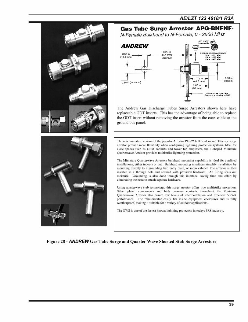
Figure 28 - ANDREW Gas Tube Surge and Quarter Wave Shorted Stub Surge Arrestors
The Andrew Gas Discharge Tubes Surge Arrestors shown here havereplaceable GDT inserts. This has the advantage of being able to replacethe GDT insert without removing the arrestor from the coax cable or theground bus panel.
The new miniature version of the popular Arrestor Plus bulkhead mount T-Series surgearrestor provide more flexibility when configuring lightning protection systems. Ideal forclose spaces such as OEM cabinets and tower top amplifiers, the T-shaped MiniatureQuarterwave Arrestor provides multistrike lightning protection.
The Miniature Quarterwave Arrestors bulkhead mounting capability is ideal for confinedinstallations, either indoors or out. Bulkhead mounting interfaces simplify installation bymounting directly to a grounding bar, entry plate, or radio cabinet. The arrestor is theninserted in a through hole and secured with provided hardware. An 0-ring seals outmoisture. Grounding is also done through this interface, saving time and effort byeliminating the need to attach separate hardware.
Using quarterwave stub technology, this surge arrestor offers true multistrike protection.Silver plated components and high pressure contacts throughout the MiniatureQuarterwave Arrestor also ensure low levels of intermodulation and excellent VSWRperformance. The mini-arrestor easily fits inside equipment enclosures and is fullyweatherproof, making it suitable for a variety of outdoor applications.
The QWS is one of the fastest known lightning protectors in todays PRS industry.

AE/LZT 123 4618/1 R3A
40
FThe Andrew GPS-KIT12 Antenna KiGrounding kits (2 each) should be insinstalled beneath an ice-bridge/grid, satellite look-angle signal ingress.
igure 29 - Andrew GPS-KIT12 Antenna Kitt is supplied with all items required for proper installation. NOTE: the LDF4talled as shown in the accompanying installation instructions. Where the GPS-KIT12 isthe antenna should be spaced at least 24 below the ice protection grid to allow for

AE/LZT 123 4618/1 R3A
41
5. SUMMARY OF EXTERIOR SITEGROUNDING
This section provides an overview of the guidelinesfor grounding an M/A-COM EDACS site. Although theareas of focus are towers, buildings, fences and relatedbonding methods, the thrust of this document is toemphasize that proper grounding is the first priority inthe installation of an M/A-COM EDACS site.
General Notes:• See the site specific grounding plan drawing for
ground rod locations. Ground rods must be 5/8" or3/4" copper-clad steel, 8 to10 feet in length.
• Ground rod spacing must be on 16' to 20' centers.• Tops of ground rods must be a minimum of 24 inches
below the soil surface.• If solid rock is encountered, contact the M/A-COM
project or program manager.• The ground rods must never be cut off because of
rock.When rock is encountered, it is acceptable to bore 4"x 10' into the rock, set ground rods and fill holes withbentonite slurry, or GEM. GEM is a groundenhancement material from ERICO/CadWeld.Contact ERICO/CadWeld at (800) 677.9089 fordetailed information.
• Grounding must be megger tested to assure 10ohms or less resistance (under typical. conditions). 5ohms is preferred.
• 2/0 copper stranded wire is specified. However, insome cases, number 2 may be used if approved by theM/A-COM project manager.
NOTES for Bonding & Attachments
• All connections other than CADWELDS must becrimped copper (BRUNDY) lugs. Dissimilar metal,Pressure type connections must have Penetrox® EOxide Inhibitor (or equivalent) applied.
• All underground connections must beCADWELDed. No aluminum connectors are tobe used. Right angle CADWELD (other than theground rods to ring connection) may be used. Allwire-to-wire connections should utilize Y or Tconnections. Right angle wire-to-wire connectionsare discouraged.
• M/A-COM Field Service or Field Servicedesignated personnel shall inspect all undergroundwelds prior to the covering and compaction of thesoil.
• No vertical jumpers should be welded(CADWELDed) within 2' of the ground rod.

AE/LZT 123 4618/1 R3A
42
Figure 30 Site Grounding Overview
SITE GROUNDING1) A 2/0 stranded bare copper wire must circle the
building 2' from the foundation and 3'underground. The corners of this ring must makeall bends and turns to right angles using a radiusof at least two (2) feet.
2) A 2/0 stranded bare copper wire must circle thetower foundation 2' from the foundation and 5'underground. This must be tied to the buildingground loop in 4 places by CADWELD. Thisconnection MUST NOT be at right angles, butshould use a Y connection.
3) See site grounding plan for ground rod locations.
4) A 2/0 stranded bare copper wire must run fromthe fence gate and corner posts to the buildingground ring or the tower ring (whichever iscloser) at a depth of 3'. These runs must have5/8" X 10' ground rods spaced every 16'-20'.These runs must be brought to ground level andsuspended above ground with inexpensive postsuntil the fencing is installed. Cables must beCadWelded to the posts.
5) A #2/0 stranded bare copper wire must be runfrom the building ring, end connected to thecopper buss bar that is located on the side of thebuilding under the cable entry bulkhead/port. Theconnection of this jumper must be made with aminimum bend radius of 9" to the building ring

AE/LZT 123 4618/1 R3A
43
and use a Y connection going to the otherdirection of the ring. All external connections tothe exterior ground ring halo must be madewith parallel CadWelds. Any lead that entersthe building must be run through a PVC pipe andattached to the building ground.
6) A 2/0 stranded bare copper wire must be runfrom the tower ring between the tower and thebuilding and must be connected to a 1" X 24" X¼" copper bus-bar (12, 3/8" holes) that will beattached to the tower with J bolts. This barwill be attached to the first diagonal crossmember of the tower above 8'-6" or a shortdistance above the ice bridge. The 2/0 groundlead must be attached to the lowest end of thebar.
7) Three (or four) similar 2/0 ground leads must berun from the tower ring to the legs of-the tower.These must be CadWelded to the tower. Iftabs or tails are provided by the towermanufacturer for this purpose, use downwardangled CadWeld. This will provide an easypath for lightning to reach the ground field. THEGROUND LEADS SHALL HAVE NO SHARPBENDS.
8) Four additional 2/0 ground leads come out of thecorners of the building (supplied as part of thebuilding) and must be connected to the 2/0building ground ring via Y CadWelds.
9) One additional jumper must be placed directlybelow the electrical service entrance port. Thismust be tied to the building ground ring.
10) Guy wires must be grounded using number 2stranded copper wire, attached to a 5/8" or 3/4"diameter X 10' long round rod. This ground leadmust be run in a straight line and must connectall guys at a single guy point. Use clampconnections only, no CadWelds to guys.Cadweld only where connections are made to theground rod. Use Penetrox® E Oxide Inhibitor orAndrew No-Oxy compound where dissimilarmetals contact, or where pressure connections aremade.
11) A 2/0 stranded/insulated lead from the towerlightning rod must be CadWelded to the towerring ground using Y connections.
12) The leads must be connected to the anchor with acompression clamp (copper or brass), or a copperstrap.

AE/LZT 123 4618/1 R3A
44
GLOSSARYAMPEREAn ampere (current) is a (coulomb/second)
ANTENNA ENTRANCEA pathway facility from the antenna to the associated equipment.
BACKBONEA facility (eg. pathway, cable or conductors) betweentelecommunications closets, the entrance facilities, and the equipmentrooms within or between buildings.
BANDWIDTH
The range within the limits of a band. The difference in frequencybetween the upper and lower 3dB power degredation responsefrequencies.
BI-PHASEFound as a power feed to most U.S. homes. Derived from a centertapped transformer, it contains two hot phases (180§) with a center tapneutral return. Normally supplied as two 120 volt single phases with 240volts available across both phases. The neutral return is usually earthgrounded.
BONDINGThe permanent joining of metallic parts to form an electricallyconductive path that will assure electrical continuity and the capacity toconduct safely any current likely to be imposed.
BONDING CONDUCTOR FOR TELECOMMUNICATIONSThe conductor that interconnects the telecommunications bondinginfrastructure to the building's service equipment (power) ground.
CAPACITANCEFor purposes of this application - measured at 1.0kHz unless otherwisestated.
CLAMPTo clip. To hold turn-on voltage as current is increased. Turn-on voltageis the same, or nearly the same, as "on" voltage drop.
CLAMPING RATIOThe ratio of voltage drop at a given current to the turn-on voltage.
CLAMPING SPEEDMeasured with full lead length using a 1kV/ns waveform in a 500system, with >300MHz or larger bandwidth.
CLOSET, TELECOMMUNICATIONSAn enclosed space for housing telecommunications equipment, cableterminations, and cross-connect cabling. The closet is the recognizedlocation of the cross connect between the backbone and horizontalfacilities.
COMBINERThe summation (combining) of multiple transmitters into onetransmission line. The peak voltage from each signal will be additiveand will be higher than the sum of the indicated power.
COMMON-MODEPertaining to signals or signal components referenced to ground.
COMMERCIAL BUILDINGA building or portion thereof that is intended for office use.
COULOMBA measurement of charge. Often used to indicate the amount oftransferred charge through a gas tube to determine gas tube life. "G"abbreviation. A coulomb is (current x time).
CROWBARTo turn-on and clamp close to ground level. Having a high turn-ontrigger voltage and a low "on" voltage.
DIFFERENTIAL MODEReferenced only between conductors (not referenced to ground).
DIPLEXER/MULTIPLEXER/COMBINERThe combining of two (or more) transmitter outputs onto onetransmission line.
DUPLEXERReceive and transmit simultaneously on one transmission line. Where aT-connector splits/combines the signals to two groups of filters. Thereceiver filter passes the receive frequency while rejecting (band stop)the transmitter's frequency. The transmitter filter passes its frequencywhile attenuating the receive frequency.
EFFECTIVELY GROUNDEDIntentionally connected to earth through a ground connection orconnections of sufficiently low impedance and having sufficientcurrent-carrying capacity to prevent the buildup of voltages that mayresult in undue hazard to connected equipment or to persons.
ELECTRICAL CLOSETA floor-serving facility for housing electrical equipment, panel boards,and controls. The closet is the recognized interface between theelectrical backbone riser and associated pathway.
EMI/RFIElectro Magnetic Interference/Radio Frequency Interference. Broadspectrum noise or interfering signals.
EMPElectro Magnetic Pulse, usually referred to as the manmade generationby detonation of a nuclear bomb at a high altitude, which generates avery fast pulse (RF) which can be captured by antennas and longunshielded lines. Sometimes referred to as NEMP, HEMP, etc.Lightning can also generate an EMP near the event. Referred to asLEMP.
ENTRANCE FACILITY, TELECOMMUNICATIONSAn entrance to a building for both public and private network servicecables (including antennae) including the entrance point at the buildingwall and continuing to and including the entrance room or space.
ENTRANCE POINT. TELECOMMUNICATIONSThe point of emergence of telecommunications conductors through anexterior wall, a concrete floor slab, or from a rigid metal conduit orintermediate metal conduit.
ENTRANCE ROOM OR APACE, TELECOMMUNICATIONSA space in which the joining of inter- or intra-buildingtelecommunications backbone facilities takes place. An entrance roommay also serve as an equipment room.
EQUIPMENT ROOM, TELECOMMUNICATIONSA centralized space for telecommunications equipment that serves theoccupants of the building. An equipment room is considered distinctfrom a telecommunications closet because of the nature or complexity ofthe equipment.
EXOTHERMIC WELDA method of permanently bonding two metals together by a controlledheat reaction resulting in a molecular bond.
FARADAY SHIELDAn electrostatic (E field) shield made up of a conductive or partiallyconductive material or grid. A Faraday cage or screen room is effectivefor protecting inside equipment from outside radiated RF energies.
FILTERING (EMI/RFI)Measured in a 500 system loaded, per MIL-STD-220.

AE/LZT 123 4618/1 R3A
45
FREQUENCY RANGEThe bandwidth over which both the listed maximum VSWR andInsertion Loss specifications are valid.
GROUNDA conducting connection, whether intentional or accidental, between anelectrical circuit or equipment and the earth, or to some conductingbody that serves in place of the earth.
GROUNDING ELECTRODEThe earth buried metallic copper or copper clad rods which are used asan direct path to ground
GROUNDING ELECTRODE CONDUCTORThe conductor used to connect the grounding electrode to the equipmentgrounding conductor, or to the grounded conductor of the circuit at theservice equipment, or at the source of a separately derived system.
GROUND IMPEDANCEThe ground resistance and the inductance/capacitance value of thegrounding system. Also called dynamic surge ground impedance.
GROUND LOOP
An undesired potential EMI condition formed when two or more piecesof equipment are interconnected and earthed for shock safety hazardprevention purposes.
GROUND RESISTANCEThe resistance value of a given ground rod or grounding system asmeasured, usually defined by a fall of potential of a 100Hz signal (2%method, see APPENDIX B Ground Measuring Techniques).
IMPEDANCEThe total opposition (resistance and reactance) a circuit offers to theflow of alternating current at a given frequency.
INFRASTRUCTURE. TELECOMMUNICATIONSA collection of those telecommunications components, excludingequipment, that together provide the basic support for the distribution ofall information within a building or campus.
INSERTION LOSSLoss of a device across the stated frequency range. This type of loss isdue to the insertion of the unit in series with a signal path.
JOULESA unit of energy. One joule for one second is equal to one watt ofpower. A Joules is (current x time x voltage).
LEAKAGE CURRENT
Undesirable flow of current through or over a surface of an insulatingmaterial or insulator. Usually measured at 50 or 60Hz with 120, 240, or440 volts AC. However, it can be AC or DC at a specific voltage and/orfrequency.
LOOP RESISTANCETotal resistance as measured across the input with the output shorted.
MAXIMUM POWERMaximum Continuous Wave (CW) transmit power, without unitdegradation.
MAXIMUM SURGEThe maximum single surge current and specified waveform that can behandled by a device without failure during the conduction of thatwaveform and which ends the life of the .
MULTI-STRIKE CAPABILITYIn most applications current sharing will occur, and in a direct strikeevent the unit will survive to work again.
PATHWAYA facility for the placement of telecommunications cable.
POWERPower - measured in watts, is expressed as (voltage X current).
RECEIVER MULTICOUPLERSometimes with an amplifier, this device has one antenna line input,and multiple receiver outputs.
RFRadio Frequencies - any and all frequencies that can be radiated as anelectromagnetic wave (plane wave).
SAFETY GROUNDThe local earth ground, or the earth ground that grounds the neutralreturn. (Neutral must only be grounded once at the entry location).
SHFSuper High Frequency - from 3000MHz to 30GHz.
SHUNT PROTECTORLine-to-ground. No power or signal passage through unit.
SINGLE PHASEA true single phase supply, usually a two-wire system with one hotphase and a neutral return. A safety earth ground is also present.
SKIN EFFECTThe tendency of rf currents to flow near the surface of a conductor. Thusthey are restricted to a small part of the cross-sectional area, which hasthe effect of increasing the resistance.
TELECOMMUNICATIONSAny transmission, emission, and reception of signs, signals, writings.images, and sounds, that is, information of any nature by cable, radio,optical, or other electromagnetic systems.
TELECOMMUNICATIONS BONDING BACKBONEA copper conductor extending from the telecommunications maingrounding busbar to the farthest floor telecommunications groundingbusbar.
TELECOMMUNICATIONS BONDING BACKBONEINTERCONNECTING BONDING CONDUCTORA conductor that interconnects the telecommunications bondingbackbones.
TELECOMMUNICATIONE CLOSET see closet telecommunications
TELECOMMUNICATIONS EQUIPMENT ROOM - see equipmentroom, telecommunications
TELECOMMUNICATIONS INFRASTRUCTURE - seeinfrastructure, telecommunications
TELECOMMUNICATIONS MAIN GROUNDING BUSBARA busbar placed in a convenient and accessible location and bonded bymeans of the bonding conductor for telecommunications to the serviceequipment (power) ground.
TERMINATION HARDWAREA device used to connect cable or wires for the ease of cross connectingor for the extension to another cable or equipment.
THREE PHASEIt consists of sinusoids 120 degrees apart on at least three wires (Delta)and often four wires (Wye). The fourth wire is a grounded neutralreturn. ID a Delta system there is no reference to ground and thus it ismore susceptible to lightning problems.

AE/LZT 123 4618/1 R3A
46
THROUGHPUT ENERGYA measure of the efficiency of a system; the rate at which the systemcan handle energy.
TOTAL SURGE ENERGYTotal sum of surge energy for all lines of a protector unit. Measured injoules. The minimum total energy that results in the failure of the unit.
TRANSFER IMPEDANCEReferring to coax, is the impedance to transfer into or outside the coaxat various frequencies usually below 1MHz. Due to loss of skin effectattenuation or shielding at these low frequencies, coax can besusceptible to interference and noise as well as the radiation of suchsignals.
TURN-ON TIME - GAS TUBE FIRINGThe amount of time that exists in the period that occurs when the rampvoltage barely exceeds the turn-on voltage of the device, and the point atwhich 50% of the peak voltage is achieved during the turn-on (crowbar)process.
UHFUltra-High Frequency - normally from 300 to 3000MHz, however inthis catalog we breakout 800 to 1000MHz separately even though it iswithin this category.
VHFVery High Frequency - from 30 to 300MHz.
VLF
Very Low Frequency - from 300Hz to 3kHz.
VOLTThe unit of measure of electomotive force. The difference of potentialrequired to make a current of 1 ampere flow through a resistance of 1ohm.
VSWRVoltage Standing Wave Ratio (VSWR). In a stationary wave system(such as a coaxial cable) the ratio of the amplitude or voltage at avoltage maximum to that of an adjacent voltage minimum.
GROUND RELATED ABBREVIATIONS AND ACRONYMS
ACACEGAWGBICSICBCCISPRDCCSACVGBEFEIAEMTFGWIGZGDTMGBMOVMUXNEMANFPANECQWSTBBTBBIBC
TCTEFTERTGBTIATMGB
alternating currentAlternating Current Equipment GroundAmerican Wire GageBuilding Industry Consulting Service InternationalCoupled Bonding ConductorInternational Special Committee on Radio Interferencedirect currentCanadian Standards AssociationCable Vault Ground BusbarEntrance FacilityElectronic Industries AssociationElectrical Metallic TubingFloor Ground WindowIndependent Ground ZonesGas Discharge tubeMaster /ground BarMain Oxidizer ValueMultiplexerNational Electrical Manufacturers AssociationNational Fire Protection AssociationNational Electrical CodeQuarter Wave StubTelecommunications Bonding BackboneTelecommunications Bonding BackboneInterconnecting Bonding ConductorTelecommunications ClosetTelecommunications Entrance FacilityTelecommunications Entrance RoomTelecommunications Grounding BusbarTelecommunications Industry AssociationTelecommunications Main Grounding Busbar

AE/LZT 123 4618/1 R3A
47
VENDOR ANDMANUFACTURER CONTACT
INFORMATION
Andrew Sales Offices
United States and CanadaAndrew Corporation10500 W. 153rd StreetOrland Park, IL U.S.A. 60462-3099Telephone: (708) 349-3300FAX: (708) 349-5444
Andrew SciComm Inc.2908 National DriveGarland, TX U.S.A. 75041-2337Telephone: (972) 840-4900FAX: (972) 278-0270
Andrew DCS2425 N. Central Exwy #800Richardson, TX U.S.A. 75080Telephone: (972) 235-7300FAX: (972) 234-6014
Andrew DCS Asia Pacific OfficeAndrew CorporationSuite 1901, Block BM P Industrial Centre18 Ka Yip St., Chai WanHong KongTelephone: +852 2975-0080FAX: +852 2558-8375
Andrew Wireless Products Group1100 Maplewood DriveItasca, IL U.S.A. 60143Telephone: (630) 250-9900 or (800)458-2820FAX: (630) 250-9917
AustraliaAndrew Australia153 Barry RoadCampbellfield, VictoriaAustralia 3061Telephone: +61 3 9357-9111FAX: +61 3 9357-9110
BrazilAndrew Industria e Comercio Ltda.Av. Comendador Camilo Julio, 1256Sorocaba, SP 18086BrazilTelephone: +55 (15) 238-4000FAX: +55 (15) 238-4001
FranceAndrew S.A.R.L.320, rue Helene BoucherB.P. 115, Z.l. Centre78531 Buc, Cedex, FranceTelephone: +33 (1) 39 24 14 70FAX: +33 (1) 39 56 51 37
GermanyAndrew GmbHDaniel-Eckhardt-Str. 3aD-45356 Essen, GermanyTelephone: +49 201 8360710Hong Kong/ChinaAndrew Hong Kong Ltd.1901 East Asia Aetna Tower308-320 Des Voeux Road CentralHong KongTelephone: +852 2515-7500FAX: +852 2515-7599
Andrew International CorporationShanghai Representative OfficeRoom 2101 - 2102No. 129 Yan An Xi RoadShanghai Overseas Chinese MansionShanghai, China 200040Telephone: +86 21 6249 9057FAX: +86 21 6249 9058
IndiaAndrew CorporationLiaison Office IndiaW 16 Greater Kailash -2New Delhi 110048IndiaTelephone: +1 91 11 622 8599FAX: +1 91 11 648 5261
ItalyAndrew S.R.L.Via Rombon,1120134 Milan, ItalyTelephone: +39 2 215611FAX: +39 2 2150490
JapanAndrew International Corp.Room 305Nagatacho TBR Building2-10-2 Nagata-choChiyoda-KuTokyo, Japan 100Telephone: +81-3-3581-0221FAX: +81-3-3581-0222
MalaysiaAndrew CorporationLevel 36, Menara Lion, No. 165Jalan Ampang, 50450Kuala Lumpur, MalaysiaTelephone: +60-3-269-6102FAX: +60-3-269-6103
MexicoAndrew Corporation Mexico, S.A. deC.V.Homero 1804, OFNA 903Col. Polanco Reforma, CP 11510Mexico D.F., MexicoTelephone: +52 5 580-3292FAX: +52 5 395-8722
RussiaAndrew AO32A, Leninsky ProspektMoscow, 117334 Russia
Telephone: +7 095 938 1875FAX: +7 095 938 1347Saudi ArabiaAndrew Corporation1st Floor, Al Khozama CenterPO Box 53215Riyadh 11583 K.S.A.Telephone: +966-1-464-1400 ext. 412FAX: +966-1-464-1400 ext. 413
South AfricaAndrew Satcom AfricaP.O. Box 786117Sandton, 214611 Commerce Crescent WestEastgate, Sandton, 2148Republic of South AfricaTelephone: +27 11 444 5041FAX; +27 11 444 5393
SpainAndrew Espana, S.A.Paseo de la Castellana 140, 4-B28046 Madrid, SpainTelephone: +34 (1) 564-73 75FAX: +34 (1) 564-29 85
SwitzerlandAndrew AGBachliwis 2B8184 Bachenbulach ZurichSwitzerlandTelephone: +41 1 861-1166FAX: +41 1 861-1183
ThailandAndrew International93/36 5th Floor, Kensington PlaceSOI 13-15 Chaengwattana RoadDonmuang DistrictBangkok 10210, ThailandTelephone: +66 2 574-3186FAX: +66 2 573-1054
United KingdomAndrew Ltd.llex BuildingMulberry Business ParkFishponds RoadWokinghamBerkshire RG41 2GYUnited KingdomTelephone: +44 118 977 6886FAX: +44 118 979 4005
Internethttp://www.andrew.com

AE/LZT 123 4618/1 R3A
48
ERICO/CADWELDAustralia6 Chilvers RoadPO Box 148Thornleigh (Sydney) NSW 2120Phone: +61-2-9479-8500Fax: +61-2-9484-9188
BelgiumPostbus 60B - 2380 Ravels 1Phone:+32-1-469-9688Fax:+32-1-469-9690
BrazilRua Irineu JoseBordon, 56505120-060, Sao Paulo Phone: +55-11-261-0111 Fax: +55-11-261-0066
Canada7575 Trans-Canada Highway,Suite 500Montreal, QuebecH4T1V6Phone: 1-800-677-9089Fax: +1-514-337-3989
ChileCasilla 16.666SantiagoPhone: +56-2-734-5022Fax: +56-2-736-9726
DenmarkStortorget 29SE-211 34 MalmöSwedenPhone: +45-46-19-19-41Fax+45-46-19-19-42
FranceRue Benoit FourneyronBoite Postale 31Zone Industrielle Sud 42161Andrezieux-Boutheon CedexPhone: +33-4-7736-5656Fax: +33-4-7755-3789
GermanyD-66851SchwanenmuehlePhone: +49-63-079-1810Fax: +49-63-079-18150
Hong KongUnit 1, 2nd Floor, Block APo Yip Building62-70 Texaco RoadTsuen Wan, New TerritoriesPhone: +852-2-764-8808Fax: +852-2-764-4486
HungaryGyali U.371097 BudapestPhone: +36-1-281-2352Fax: +36-1-281-2353
IndonesiaLevel 43, Wisma 46Kota BNI Jalan Jend, SudirmanKav.1Jakarta 10220Phone: +62-21-574-8852Fax: +62-21-574-8854ItalyVia Edison Nr. 5020019 SettimoMilanesePhone: +3902-3350-1326Fax: +3902-3350-1304
MexicoRecursos Hidraulicos#1 54060 Tlalnepantla EstadoPhone: +52-5-398-0033Fax: +52-5-397-8634
NetherlandsPostbus 487NL-5000 AL TilburgPhone: +31-13-583-5400Fax: +31-13-583-5499
NorwayPostboks 148NO-1366 LysakerPhone: +47-6-753-1200Fax: +47-6-712-4268
Poland54-613 Wroclawul. Krzemieniecka 17Phone: +48-71-574-827Fax: +48-71-342-31-19
Singapore1 Jalan RemajaHillview House, #05-04Singapore 668662Phone: +65-763-2477Fax: +65-763-2379
South AfricaStand 322-5th StreetWynberg, GautengPO Box 784Bramley 2018Phone: +27-11-786-9188Fax: +27-11-786-6216
SpainC/ Provenza 288, Pral.08008 BarcelonaPhone: +34-93-467-7726Fax: +34-93-467-7725
SwedenStortorget 29SE-211 34 MalmöPhone: +46-40-611-1360Fax: +46-40-611-9415
SwitzerlandPra Pury 7d3280 MurtenPhone: +41-26-672-9999Fax: +41-26-672-9998
ThailandLevel 23, CP Tower313 Silom RoadBangkok 10500Phone: +66-2-231-8282Fax: +66-2-231-8283United Kingdom52 Milford RoadReading, BerkshireRG1 8LJPhone: +44-118-958-8386Fax: +44-118-959-4856
USA34600 Solon RoadSolon, Ohio 44139Phone: +1-440-248-0100Fax: +1-440-248-0723
Internethttp://www.glt.com.au
Lyncole XITGrounding andAEMC Ground TestEquipment3547 Voyager St., # 104Torrance, CA 90503Phone: +1-800-962-2610Fax: +1-310-214-1114
Internethttp://www.lyncole.com
ValmontMicroflect
Valmont Industries, Inc.P.O. Box 358Valley, NE 68064Phone: +1-800-825-6668Fax: +1+402-343-0658
Internethttp:// www.valmont.com

AE/LZT 123 4618/1 R3A
49
Joslyn ElectronicSystems Company6868 Cortona DriveSanta Barbara Reseaarch ParkGoleta, CA 93116-0817Phone: +1-800-752-8068Fax (USA): +1-805-968-0922Fax (Intl): +1-805-968-1601Internethttp://www.jesc.com
PolyPhaser CorporationAndTranstector Systems, IncP.O. Box 9000Minden, Nevada 89423-9000Phone: +1-800-325-7170Fax: +1-775-782-4476Internethttp://www.polyphaser.com

AE/LZT 123 4618/1 R3A
50
APPENDIX AMICROFLECT DEVICES
& PART NUMBERS ASSOCIATED WITH GROUNDING OF TOWERS, ICE-BRIDGES, GUY ANCHORS, AND CABLE ENTRY PORTS.
Figure A-1 3 Leg Tower Grounding Kit
Figure A-2 Guyed Tower Grounding Kit

AE/LZT 123 4618/1 R3A
51
Figure A-3 Four Leg Tower Grounding Kit
Figure A-4 Monopole Tower Grounding Kit

AE/LZT 123 4618/1 R3A
52
Figure A-5 Cable Entry Port Grounding Kit
Figure A-6 10' Self-Supported W/G Bridge Grounding Kit

AE/LZT 123 4618/1 R3A
53
Figure A-7 20' Ice Bridge Grounding Kit
Figure A-8 30' Self-Supported W/G Bridge Grounding Kit

AE/LZT 123 4618/1 R3A
54
Figure A-9 3 and 4 Leg Tower Grounding Kit

AE/LZT 123 4618/1 R3A
55
This page intentionally left blank

M/A-COM Wireless Systems3315 Old Forest RoadLynchburg, Virginia 24501(Outside USA, 434-385-2400) Toll Free 800-528-7711www.macom-wireless.com Printed in U.S.A.