aei rail & road manager - aei rf identification. automatic vehicle deletion ... aei rail &...
TRANSCRIPT

AEI RAIL & ROAD MANAGER User Manual
August 31, 2012
Copyright 2005 Softrail All rights reserved

AEI Rail & Road Manager
ii August 31, 2012
Softrail 1098 Venetia Road
Eighty-Four, PA 15330
Tel. 888 872-4612 (toll free US and Canada only) Tel. 724 942-1473 Fax. 724 942-1480
E-mail [email protected] Web Page www.aeitag.com

AEI Rail & Road Manager
iii August 31, 2012
Table of Contents 1. INSTALLATION ....................................................................................................... 1 1.1. Installing AEI Rail &Road Manager ...............................................................................1 1.2. Starting the Program ................................................................................................1 2. BRIEF OVERVIEW.................................................................................................... 1 3. OPTIONS ............................................................................................................... 2 3.1. Information About Program Options & Vehicle Limits ......................................................2 4. TECHNICAL SUPPORT AND UPDATES ........................................................................ 3 5. TERMINAL DISPLAY ................................................................................................ 4 5.1. Vehicle Database and Terminal Layout Files...................................................................4 5.2. Moving a Vehicle.......................................................................................................4 5.3. Moving Multiple Vehicles ............................................................................................5 5.4. Moving Around the Terminal Display.............................................................................6 5.5. Information Displayed by the Track/Road Name ............................................................6 5.6. Zoom in and Zoom out ..............................................................................................6 5.7. Vehicle Justification...................................................................................................7 6. VEHICLE INFORMATION DISPLAY............................................................................... 8 6.1. General Vehicle Information Display..............................................................................8 6.2. EDI 418 Data Display ..............................................................................................11 6.3. UMLER/TAG Data Display........................................................................................12 6.4. Movement History...................................................................................................13 7. USER DEFINED FIELDS........................................................................................... 14 8. USER DEFINED VEHICLE COLORS............................................................................. 16 9. USER DEFINED STATUS LINE .................................................................................. 17 10. ADD, DELETE OR FIND A VEHICLE............................................................................ 18 10.1. Manually Adding a Vehicle ........................................................................................18 10.2. Manually Deleting a Vehicle ......................................................................................18 10.3. Automatic Vehicle Deletion .......................................................................................19 10.4. Finding a Vehicle.....................................................................................................19 10.5. Automatic Deletion of Vehicles ..................................................................................19 11. VEHICLE LIST DISPLAY........................................................................................... 20 11.1. Vehicle List Search Criteria.......................................................................................20 11.2. Vehicle List Display..................................................................................................23 11.3. Column Widths.......................................................................................................23 11.4. Column Setup.........................................................................................................23 11.5. Vehicle Information Display .......................................................................................24 11.6. Vehicle Comments ..................................................................................................24 11.7. Finding a Vehicle on the Terminal Display ....................................................................25 11.8. Exporting Vehicle Data .............................................................................................25 11.9. Printing the Vehicle List ...........................................................................................25 11.10. Listing or Printing a Single Track’s Vehicle Inventory .....................................................27 12. PASSWORDS....................................................................................................... 27 12.1. Password Maintenance Dialog ..................................................................................27 12.2. Password Entry ......................................................................................................28 12.3. Logging in a User....................................................................................................28 13. TRANSACTION LIST............................................................................................... 29 13.1. Displaying the Transaction List ..................................................................................29 13.2. Transaction List Display ...........................................................................................29 13.3. Printing the Transaction List .....................................................................................31 13.4. Transaction File Structure ........................................................................................31 14. ARCHIVE LIST ...................................................................................................... 31

AEI Rail & Road Manager
iv August 31, 2012
14.1. Displaying the Archive List ........................................................................................31 14.2. Archive List Display .................................................................................................32 14.3. Restoring a Deleted Vehicle ......................................................................................33 14.4. Printing the Archive List ...........................................................................................33 14.5. Archive File Structure ..............................................................................................33 15. RESTORE FIELDS...................................................................................................33 15.1. Restore Field Dialog.................................................................................................34 16. EXPORT DATA......................................................................................................34 16.1. Export Dialog ..........................................................................................................35 16.2. Export Vehicle Inventory on a Single Track/Road ..........................................................36 17. REVERSE TRACK INVENTORY..................................................................................36 18. SUMMARY OF TRACK/ROAD SHORTCUT FUNCTIONS.................................................36 19. FILE MAINTENANCE ..............................................................................................37 19.1. Manual File Backup .................................................................................................37 19.2. Automatic Backup of Vehicle Data File ........................................................................37 19.3. Automatic Deletion of Transaction Records .................................................................38 19.4. Automatic Deletion of Communication Records ............................................................39 19.5. Network File Maintenance Manager ...........................................................................39 20. MAINTENANCE LOG FILE........................................................................................39 21. MEMORIZED LIST MAINTENANCE ............................................................................40 22. UMLER DATABASE ...............................................................................................41 22.1. Loading the UMLER Database from a CD....................................................................42 22.2. Searching for Vehicle UMLER Data ............................................................................42 23. DRAW TERMINAL LAYOUT.....................................................................................43 23.1. Drawing Track/Road Symbols on the Layout ...............................................................44 23.2. Clearing Symbols from the Terminal Layout .................................................................44 23.3. Inserting and Deleting Columns and Rows ...................................................................44 23.4. Duplicating Straight Track/Road Symbols ...................................................................45 23.5. Track/Road Names ................................................................................................45 23.6. AEI Reader Site Information ......................................................................................47 23.7. Selecting a Group of Grid Squares..............................................................................48 23.7.1. Clearing a Selected Group of Squares.........................................................................49 23.7.2. Moving a Selected Group Of Squares..........................................................................49 23.7.3. Using a Selected Group of Squares to Insert and Delete Columns and Rows .....................49 23.8. Bitmaps (User Generated Graphics) ...........................................................................50 23.8.1. Adding Bitmaps ......................................................................................................50 23.8.2. Modifying Bitmaps...................................................................................................52 23.8.2.1. Moving Bitmaps ................................................................................................52 23.8.2.2. Deleting Bitmaps...............................................................................................52 23.8.2.3. Changing Bitmaps .............................................................................................53 23.8.2.4. Duplicating Bitmaps ...........................................................................................53 23.8.3. Bitmap Maintenance................................................................................................53 23.9. User Text Areas......................................................................................................54 23.9.1. Adding Text Areas...................................................................................................54 23.9.2. Modifying Text ........................................................................................................56 23.9.2.1. Moving Text Areas.............................................................................................56 23.9.2.2. Deleting Text Areas ...........................................................................................56 23.9.2.3. Changing Text Areas..........................................................................................57 23.9.2.4. Duplicating Text Areas .......................................................................................57 23.10. Background and Foreground General Rules .................................................................57 23.11. Saving a Terminal Layout File ....................................................................................58 23.12. Password Protection ...............................................................................................58

AEI Rail & Road Manager
v August 31, 2012
23.13. General Drawing Guidelines ......................................................................................58 24. NETWORKING...................................................................................................... 58 25. PORTABLE AEI READERS........................................................................................ 59 25.1. Encompass 1i and SmartScan Model 2400 Portable Readers .......................................60 25.2. SmartScan Model 2200 Portable Reader ...................................................................61 25.2.1. Establishing the SmartScan Portable Reader to Computer Interface ................................61 25.2.2. Establishing Communications between the Computer and the Portable Reader..................62 25.2.3. Problems Connecting with the Portable Reader............................................................64 25.2.4. Transferring Tag Data from the Portable Reader .........................................................64 25.2.5. Portable Reader Maintenance Code ...........................................................................69 26. AI2006 WAYSIDE AEI TAG READERS ....................................................................... 71 26.1. Wayside AEI Reader Communications ........................................................................72 26.2. Identifying the AI2006 Reader ..................................................................................74 26.2.1. Turning on Wayside AEI Reader Communications .........................................................75 26.2.2. Wayside AEI Reader Status ......................................................................................75 26.2.3. Enabling/Disabling Wayside Reader Communications ...................................................76 26.2.4. Monitoring Communications .....................................................................................76 26.3. Communication Logs ...............................................................................................77 27. Email Setup ......................................................................................................... 78 27.1. Maintenance File Email Addresses .............................................................................79 27.2. Reader Problem Email Setup ....................................................................................80 27.3. Sending a Test Email ...............................................................................................83 28. EMAIL NOTIFICATIONS ........................................................................................... 83 28.1. Displaying the Email Records ....................................................................................83 28.2. Adding an Email Record ...........................................................................................84 28.3. Changing an Email Record........................................................................................87 28.4. Delete an Email Record............................................................................................88 28.5. Sending a Test Email ...............................................................................................88 28.6. Email Return, Copy and Test Email Addresses Setup.....................................................88 29. EDI 418 FILE MESSAGE FOLDERS............................................................................ 89 30. FTP Setup ........................................................................................................... 89 31. SYSTEM SPECIFICATIONS....................................................................................... 91

AEI Rail & Road Manager
vi August 31, 2012
List of Figures Figure 1 - About Display ..........................................................................................................................................................3 Figure 2 - Terminal Display......................................................................................................................................................5 Figure 3 - Zoomed out Terminal Display..................................................................................................................................7 Figure 4 - Rail Vehicles Right Justified ....................................................................................................................................7 Figure 5 - Vehicle Information Status Line ..............................................................................................................................8 Figure 6 - Vehicle General Data Display ..................................................................................................................................9 Figure 7 - EDI 418 Data Display ............................................................................................................................................11 Figure 8 - UMLER/TAG Data Display...................................................................................................................................13 Figure 9 - Movement History Display ....................................................................................................................................14 Figure 10 - User Defined Fields..............................................................................................................................................15 Figure 11 - User Defined Colors .............................................................................................................................................16 Figure 12 - User Defined Status Line......................................................................................................................................18 Figure 13 - Find a Vehicle Display .........................................................................................................................................19 Figure 14 - Automatic Vehicle Deletion .................................................................................................................................20 Figure 15 - Vehicle List Memorized Search and Report Layout ............................................................................................20 Figure 16 - Vehicle List Search Criteria .................................................................................................................................21 Figure 17 - Vehicle List Display.............................................................................................................................................23 Figure 18 - Vehicle List Column Order Setup Display...........................................................................................................24 Figure 19 - Vehicle List Save Print Layout.............................................................................................................................25 Figure 20 - Vehicle List Print Display ....................................................................................................................................26 Figure 21 - Password Maintenance Dialog .............................................................................................................................27 Figure 22 - Transaction Search Dialog ...................................................................................................................................29 Figure 23 - Transaction List....................................................................................................................................................30 Figure 24 - Archive Search Dialog .........................................................................................................................................32 Figure 25 - Archive List Display ............................................................................................................................................32 Figure 26 - Restore Field Dialog.............................................................................................................................................34 Figure 27 - Export Dialog .......................................................................................................................................................35 Figure 28 - Shortcut Pop-up Menu..........................................................................................................................................37 Figure 29 - File Maintenance ..................................................................................................................................................38 Figure 30 - File Maintenance Manager Selection ...................................................................................................................39 Figure 31 - Maintenance Log..................................................................................................................................................40 Figure 32 - Memorized Lists...................................................................................................................................................41 Figure 33 - Find UMLER Data ...............................................................................................................................................42 Figure 34 - Draw Terminal Layout Display............................................................................................................................43 Figure 35 - Draw Terminal Layout Pop-up Menu ..................................................................................................................45 Figure 36 - Track/Road Information Dialog ...........................................................................................................................46 Figure 37 - Reader Site Setup Dialog......................................................................................................................................47 Figure 38 - Selected Group of Grid Squares ...........................................................................................................................48 Figure 39 - Using a Group of Selected Squares to Insert Columns.........................................................................................50 Figure 40 - Inserting a Bitmap ................................................................................................................................................51 Figure 41 - Foreground Bitmap...............................................................................................................................................52 Figure 42 - Deleting a Bitmap.................................................................................................................................................53 Figure 43 - Bitmap Maintenance.............................................................................................................................................54 Figure 44 - Inserting Text .......................................................................................................................................................55 Figure 45 - Color Dialog.........................................................................................................................................................55 Figure 46 - Foreground Text Area ..........................................................................................................................................56 Figure 47 - Deleting a Text Area ............................................................................................................................................57 Figure 48 - Encompass 1i and 2400 Portable AEI Readers ....................................................................................................59 Figure 49 - Encompass 1i and SmartScan Model 2400 Portable Reader TCP/IP Setup .........................................................60 Figure 50 - AEI RR TCP/IP Setup Dialog ..............................................................................................................................61 Figure 51 - Portable Reader Sub-menu ...................................................................................................................................62 Figure 52 - Searching for Portable Reader..............................................................................................................................62

AEI Rail & Road Manager
vii August 31, 2012
Figure 53 - Portable Reader Connection Status...................................................................................................................... 63 Figure 54 - Portable Reader Parameters ................................................................................................................................. 63 Figure 55 - List of Tag Sessions ............................................................................................................................................. 65 Figure 56 - Transferring Sessions Data Progress Message..................................................................................................... 65 Figure 57 - Portable Reader Data Track Selection ................................................................................................................. 66 Figure 58 - Cars Added by the Portable Reader ..................................................................................................................... 67 Figure 59 - Compare Track Tag Lists..................................................................................................................................... 68 Figure 60 - Adding Comparison Vehicle Tags ....................................................................................................................... 69 Figure 61 - Maintenance Codes.............................................................................................................................................. 70 Figure 62 - Added Maintenance Code.................................................................................................................................... 71 Figure 63 - AI2006 Network Yard AEI Reader...................................................................................................................... 71 Figure 64 - AI2006 Network Yard AEI Reader TCP/IP Setup............................................................................................... 72 Figure 65 - AI2006 TCP/IP Setup Dialog .............................................................................................................................. 73 Figure 66 - AI2006 Reader Site Setup Dialog ........................................................................................................................ 74 Figure 67 - Wayside AEI Reader Server Selection ................................................................................................................ 75 Figure 68 - Wayside AEI Reader Status................................................................................................................................. 75 Figure 69 - Enabling/Disabling Wayside AEI Reader............................................................................................................ 76 Figure 70 - Communications Monitor .................................................................................................................................... 77 Figure 71 - Communications Log........................................................................................................................................... 78 Figure 72 - Email Setup.......................................................................................................................................................... 79 Figure 73 - Maintenance File Email Addresses...................................................................................................................... 79 Figure 74 - Reader Problem Email Setup ............................................................................................................................... 81 Figure 75 - Email Body Text .................................................................................................................................................. 82 Figure 76 - Email Record List Display................................................................................................................................... 84 Figure 77 - Email Text File .................................................................................................................................................... 85 Figure 78 - Email Reader Reporting List Display .................................................................................................................. 86 Figure 79 - Add Reporting Readers........................................................................................................................................ 87 Figure 80 - Email Notification Addresses .............................................................................................................................. 88 Figure 81 - EDI 418 Folder Setup Display ............................................................................................................................. 89 Figure 82 - FTP Setup ............................................................................................................................................................ 90


AEI Rail & Road Manager
1 August 31, 2012
1. INSTALLATION
1.1. Installing AEI Rail &Road Manager
The AEI Rail & Road Manager comes on a CD-ROM. To install the program, insert the CD-ROM into the CD-ROM drive. The installation program should automatically start. If it does not start, click the Start and then the Run buttons. In the Open box, type d:setup.exe if your CD-ROM is the D drive on your computer. If it is not the D drive, type the appropriate drive letter followed by a colon and then autorun.exe (ex. e:setup.exe, f:setup.exe, etc.).
When the installation program starts follow the installation instructions. When the installation is complete an icon will appear on your desktop.
1.2. Starting the Program
To start the program, click the Start button, point to Program and then to the AEI Rail & Road Manager folder and click on the AEI Rail & Road Manager program.
After starting the program, the Terminal display appears (see Figure 2).
2. BRIEF OVERVIEW AEI Rail & Road Manager is a low cost solution for maintaining vehicle (rail car, trailer, container, etc.) inventory:
in a small yard or industrial terminal area on a short line railroad in a group of separate yards or terminals
The main feature of the system is the graphical representation of the location of vehicles on a yard or terminal diagram. The system includes software that allows users to easily create and maintain yard or terminal diagrams of their facilities, which can then be incorporated into the system.
Vehicles can be manually moved on the yard or terminal diagram by simply dragging the vehicle with the mouse to its new location. The system also has the capability to automatically track vehicle movements according to information received from AEI readers (portable and wayside) or other types of sensors.
The AEI Rail & Road Manager program is designed to handle multiple facilities or allow multiple users to view information at a single facility. From a central location users can monitor vehicle information at several facilities, or several users at the same facility can obtain up-to-date information on vehicle locations and status. The system also has password protection, which prevents unauthorized users from viewing or updating information. Any change to a vehicle’s position or data is recorded in a transaction file with the name of the user who made the change.

AEI Rail & Road Manager
2 August 31, 2012
Users can specify the types of records they want to maintain on a vehicle. They can easily search the vehicle database to find vehicles with particular attributes, e.g. all vehicles that have been in the facility for over 8 days. Users can also specify that the colors of vehicles on the terminal diagram be based on information contained in their respective data records. For example, all vehicles that are bad order could be displayed in blue.
Records are archived for vehicles leaving (deleted from) the facility. This information is used to reconstruct records for vehicles returning to the facility. Fields to be automatically restored may be specified by the user.
The user can also export the vehicle database by creating a delimited text file. A delimited text file can then be accessed by other commercial or user generated programs. The transaction and archive files are delimited text files. The system has the capability to search, display and print these files. The user can customize the printouts by specifying a title, the character font, the fields to be included, and the paper orientation.
3. OPTIONS
3.1. Information About Program Options & Vehicle Limits
AEI Rail & Road Manager has a number of options and places limits on the number of vehicles that can be in the database at any given time. The options include:
The ability to interface to wayside AEI readers The ability to interface to portable AEI readers (the SmartScan Model 2200, the
SmartScan Model 2400 and the Encompass 1i) The ability to use the system on a network (allowing multiple users to access the
database at any given time) The ability to look up rail car data in UMLER The ability to check and display the rail car orientation (this is important if rail
cars are going through a rotary dumper since the rotary coupler is only on one end of the rail car and must be coupled to a fixed coupler on the adjacent car)
The ability to receive EDI 418 (advance consist) messages from the serving railroad
All copies of AEI Rail & Road Manager are capable of looking up a subset of a rail car’s UMLER data containing vehicle type, coupler to coupler length, number of axles, number of platforms, tare weight and capacity weight. To use this feature a subset of UMLER must be loaded into the program’s database from a CD ROM purchased from Softrail (see Paragraph 22).
The program limits the number of rail vehicles that can be in its database at any given time. These limits are set at 100, 200, 300, 400 and 5,000.

AEI Rail & Road Manager
3 August 31, 2012
To determine the options available and car limits for your copy of AEI Rail & Road Manager, click the Help menu and then the About item. The display in Figure 1 will then appear.
Figure 1 - About Display
The About Display also shows your serial number and the version of the program you have installed.
4. TECHNICAL SUPPORT AND UPDATES Periodically Softrail issues maintenance releases and new versions of this program. Maintenance releases are free and correct problems found with the program and/or provide minor enhancements to the program. Before contacting us with problems we suggest that you check our web page at www.signalcc.com to insure that you have the latest maintenance release of the program. You can also go to our web page by clicking the appropriate web page item under the program’s Web Page menu at the top of the screen.
Technical support is free for the first 90 days after purchase. A maintenance agreement can be purchased to extend the period of technical support.

AEI Rail & Road Manager
4 August 31, 2012
For technical support or more information on the maintenance agreement contact Softrail at:
Softrail 1098 Venetia Road Eighty-Four, PA 15330 Tel. 888 872-4612 (toll free US and Canada only) or 724 942-1473 Fax. 724 942-1480 E-mail [email protected] Web Page www.aeitag.com
5. TERMINAL DISPLAY
5.1. Vehicle Database and Terminal Layout Files
The Terminal Display graphically shows the location of each rail vehicle in the terminal on a diagram of the user’s facility (see Figure 2). Two files are necessary to generate this display. These are the vehicle database file and the terminal layout file. These files use the “.car” and “.lay” file extensions, respectively.
There can be an unlimited number of vehicle database and terminal layout files. Each vehicle database file has an associated terminal layout file which is loaded with it. The names of the vehicle database and the terminal layout files that are currently in use are displayed in the tool bar in the upper left-hand corner of the screen (see Figure 2).
The user can create or load another vehicle database file by choosing either the New Vehicle File or Open Vehicle File menu item in the File menu. The terminal layout file used for the current vehicle database file can also be changed by choosing the Open Layout File menu item in the File Menu (please note that this function is disabled in the Portable Lite version of the program).
Vehicles are assigned locations by track/road name and position on the track/road from the left side of the screen. If the terminal layout file changes the location of a track/road, the vehicles assigned to that track/road will be moved with the track/road. If a track/road to which vehicles have been previously assigned no longer exists, a track/road will temporary be created and displayed below all of the other tracks/roads on the screen.
5.2. Moving a Vehicle
To move a vehicle on this display, place the cursor on the vehicle, hold the left mouse button down and begin to move (drag) the cursor. This will cause the cursor to take the shape of the vehicle with an arrow. By holding the left button down you can drag

AEI Rail & Road Manager
5 August 31, 2012
the cursor to the new track/road position in the terminal. When you release the left button, the vehicle will automatically move to the track/road. Vehicles will be positioned beginning with the left most position on a track/road/slot.
Figure 2 - Terminal Display
A vehicle can be placed between two adjacent vehicles already on the track by moving it into the space between the two vehicles and releasing the left mouse button. The vehicles will spread apart, allowing the moved vehicle to fit between them.
As a vehicle is dragged to a new location a large “X” will appear over the vehicle any time it is not at a “legal” drop position. For example, you cannot drop a car at a switch or between two tracks/roads.
Please note that when a vehicle (or group of vehicles) is dragged near the edge of the screen, the screen will automatically scroll in the direction of the movement.
5.3. Moving Multiple Vehicles
To move multiple vehicles, the vehicles to be moved must be selected. To select a vehicle on the display, place the cursor on the vehicle and click the left mouse button.

AEI Rail & Road Manager
6 August 31, 2012
When a vehicle is selected on this display, a blue rectangle will appear above the vehicle ID. This rectangle will remain until some action is taken on the vehicle or another vehicle is selected.
Multiple vehicles on a track/road can be selected. After selecting the first vehicle, place the cursor on the next vehicle to be selected and click the left mouse button while holding down the control key on the keyboard. You can select as many vehicles on a single track/road as you want. If you select a vehicle on another track/road, all previous selections will be canceled.
You can also select a range of vehicles on a single track/road by selecting the first vehicle and then placing the cursor on the last vehicle and clicking the left mouse button while holding down the shift key. All vehicles between the first and the last vehicle you selected will also be selected and have a blue rectangle around their ID’s.
To move a group of vehicles, select the vehicles, place the cursor on any one of the selected vehicles, hold the left mouse button down and drag the cursor to the new track/road position. When the left button is released, the group of vehicles will automatically move to the new track/road position.
5.4. Moving Around the Terminal Display
The user can use Windows’ normal vertical and horizontal scroll bars to move around the terminal on the display. The arrows, page up, page down, home and end keys can also be used.
5.5. Information Displayed by the Track/Road Name
The number of vehicles positioned on a track/road is displayed next to the track/road name. As vehicles are added or removed from the track/slot/road the number will automatically increment or decrement, respectively.
An “O” and/or “D” may also appear near the track/road name. An “O” indicates the track/road is located outside of the terminal (see Paragraph 23.5) and a “D” indicates that vehicles located on this track/road will automatically be deleted from the system after a user-specified period of time (see Paragraph 10.5).
5.6. Zoom in and Zoom out
The Terminal Display has a zoom-in and zoom-out feature (see Figure 3). There are two ways to zoom in or zoom out. One way is via the Zoom In and Zoom Out button in the toolbar near the top of the screen. Simply click these buttons to zoom in or zoom out.
The second method is to place the mouse pointer anywhere on the Terminal Display where a vehicle or track/road is not located and click the right mouse button. This will cause the screen to move from the zoom-in view to the zoom-out view or vice versa. It will also center the new view where the mouse was pointed in the old view.

AEI Rail & Road Manager
7 August 31, 2012
Because there is limited room to display track/road names and vehicle identifications, these are not displayed when the screen is zoomed out. However, by placing the mouse pointer on the vehicle, information about the vehicle will be displayed in the status line near the top of the screen.
Vehicles can be selected and moved when the screen is zoomed out.
Figure 3 - Zoomed out Terminal Display
5.7. Vehicle Justification
Vehicles can be justified to the left end or the right end of the tracks. In Figure 3 they are left justified. To right justify the vehicles click the Right Justify button next to the Zoom In button. This will cause them to be right justified on the tracks (see Figure 4).
Figure 4 - Rail Vehicles Right Justified

AEI Rail & Road Manager
8 August 31, 2012
6. VEHICLE INFORMATION DISPLAY There are several ways to obtain information on a vehicle from the Terminal Display. The simplest is to place the cursor on the vehicle. This causes the status line located below the tool bar at the top of the screen to display information about the vehicle (see Figure 5).
Figure 5 - Vehicle Information Status Line
From left to right, this status line shows the vehicle identification, the time in the terminal, the time out of the terminal, and the contents in the vehicle’s Status, Consist, Type and seven user defined fields. If the Terminal Display is zoomed out, the status line will also display the vehicle’s location after the vehicle’s identification.
To display more information about a vehicle press the right mouse button while the mouse pointer is on the vehicle. This action causes the General Vehicle Information display to appear.
6.1. General Vehicle Information Display
Figure 6 shows the display of the rail car's general data. The Track field shows the current track location of the vehicle if the vehicle has arrived in the terminal. The three-digit number after the dash is the position of the vehicle on the track. If this number is 001, then the vehicle is first car at the left end of the track. If the vehicle has not yet arrived in the terminal, this field has the identifier of the train in which the vehicle will arrive.
The Time on Track field has the date and time the vehicle was placed on the track. If the vehicle has not yet arrived in the terminal, this field will contain the vehicle's latest estimated time of arrival (ETA).
Data in the Time in Terminal or Time out of Terminal fields can either be entered manually or generated from AEI reader input. When a vehicle is reported as having entered the terminal, the date and time of the vehicle's movement into the terminal will appear in the Time in Terminal field.
When a vehicle is reported by one of the designated AEI readers as having left the terminal, the date and time the vehicle passed the reader will appear in the Time out of Terminal field.

AEI Rail & Road Manager
9 August 31, 2012
Figure 6 - Vehicle General Data Display
The user can enter up to 20 alphanumeric characters into the Status and Consist fields or select from previous user entries for the fields, which are obtained by clicking the button on the right side of the each field’s box.
For the Vehicle Type field the user can only choose a value from a pre-existing list of entries, which is obtained by clicking the button on the right side of the field. This field is used to determine the vehicle’s graphical representation on the Terminal display. The system will automatically enter a vehicle type into this field based on the data it finds in its internal UMLER file about the vehicle.
The Vehicle Information display includes two Maintenance Code fields. If information about the vehicle came from a portable reader, one or both of these fields may have an entry. To enter or change the code displayed in a Maintenance Code field, click the button at the right side of the field to display the list of codes (e.g., 00 Angle Cock, 01 Air Brakes), and select a code by clicking on it. To remove a maintenance code, select none from the list of codes. See Paragraph 25.2.5 for instructions on how to update the list of maintenance codes.
AEI Rail & Road Manager
10 August 31, 2012
Normally, the AEI readers determine a vehicle's orientation. The user, however, can manually change the vehicle's orientation by changing the value in the Orientation field.
There are seven fields in this display designated as not assigned. These fields can be assigned names by the user. Each field will accept up to 20 alphanumeric characters. The user defines these fields by calling up the User Defined Fields display (see Figure 10).
The Comments field allows the user to type up to 200 characters of information about a vehicle. The user may use the Enter key to create multiple lines in this display. A vertical scroll bar is available for scrolling this display.

AEI Rail & Road Manager
11 August 31, 2012
6.2. EDI 418 Data Display
Figure 7 shows a typical display of the data the system receives about a vehicle from an EDI 418 message. These fields will be continuously updated as new EDI 418 messages are received about the vehicle. The user can modify the information in these fields, but any new EDI 418 messages will overwrite user-entered information.
Please note in the Equipment Status Code field the data entered can only be the two-character code or the words "Load" and "MTY". The system translates "Load" to the "L" code and "MTY" to the "W" code.
Figure 7 - EDI 418 Data Display

AEI Rail & Road Manager
12 August 31, 2012
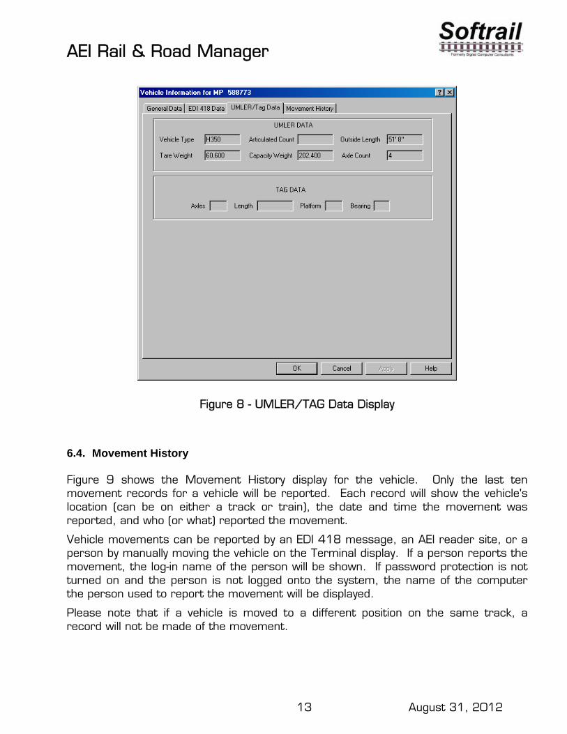
6.3. UMLER/TAG Data Display
Figure 8 shows the display of UMLER and AEI tag data for a vehicle.
The system maintains a subset of an UMLER database. This subset contains only the following fields:
Vehicle Type Articulated Count Outside Length Tare Weight Capacity Weight Axle Count
If a vehicle is not found in one of the UMLER databases, all UMLER fields will be blank. The user cannot modify these fields.
Any AEI tag data received from the AEI reader system will appear in the fields at the bottom of the display. The user cannot modify these fields.
AEI Rail & Road Manager
13 August 31, 2012
Figure 8 - UMLER/TAG Data Display
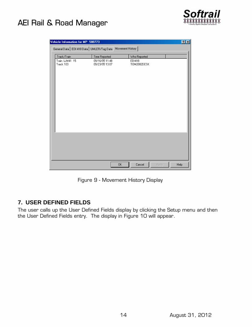
6.4. Movement History
Figure 9 shows the Movement History display for the vehicle. Only the last ten movement records for a vehicle will be reported. Each record will show the vehicle's location (can be on either a track or train), the date and time the movement was reported, and who (or what) reported the movement.
Vehicle movements can be reported by an EDI 418 message, an AEI reader site, or a person by manually moving the vehicle on the Terminal display. If a person reports the movement, the log-in name of the person will be shown. If password protection is not turned on and the person is not logged onto the system, the name of the computer the person used to report the movement will be displayed.
Please note that if a vehicle is moved to a different position on the same track, a record will not be made of the movement.
AEI Rail & Road Manager
14 August 31, 2012
Figure 9 - Movement History Display
7. USER DEFINED FIELDS The user calls up the User Defined Fields display by clicking the Setup menu and then the User Defined Fields entry. The display in Figure 10 will appear.

AEI Rail & Road Manager
15 August 31, 2012
Figure 10 - User Defined Fields
This display allows the user to customize what data will be included in the vehicles’ data records. For example, a user might want to have the vehicles’ tare, capacity, and actual weights included in the vehicles’ data records. To do this he would first enter, via this display, a field name of up to 20 alphanumeric characters for each new field he wants to include in the vehicles’ data records. He would subsequently place the appropriate data in the fields for each vehicle via the Vehicle Information display.
Instead of entering data into a particular field, the user can define a formula for the field. The program will use this formula to compute a value for the field. For example, the value for the Revenue field, as shown in Figure 10, will be calculated by subtracting the tare weight from the actual weight.
Formulas can use the +, - * and / operators on the contents of any of the numeric fields defined by the user. Constant values can also be used in the formulas. For example, if we wanted the revenue weight to be in tons, the formula we would use would be “(Actual-Tare)/2000”.
Fields that are used in formulas must be defined as being Numeric in the Data Type field.
The User Defined Fields display also allows the user to specify if a customized field is to be left, center, or right justified. This information is used when the field is displayed or printed. For example, if a field contained tare weights, one would probably want to right justify it so that the numbers would line up on the right side of the column when printed.
The user can change the name of a User Defined field at any time. The field’s data in the vehicles’ records will not be modified by this change.
AEI Rail & Road Manager
16 August 31, 2012
If a user deletes a field name via this display the name for the field in the Vehicle Information display will return to “not assigned”. The data the user entered into this field for various vehicles will be retained in the vehicles’ data records [not deleted].
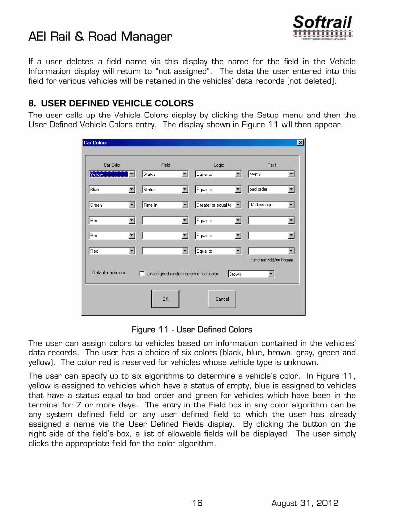
8. USER DEFINED VEHICLE COLORS The user calls up the Vehicle Colors display by clicking the Setup menu and then the User Defined Vehicle Colors entry. The display shown in Figure 11 will then appear.
Figure 11 - User Defined Colors
The user can assign colors to vehicles based on information contained in the vehicles’ data records. The user has a choice of six colors (black, blue, brown, gray, green and yellow). The color red is reserved for vehicles whose vehicle type is unknown.
The user can specify up to six algorithms to determine a vehicle’s color. In Figure 11, yellow is assigned to vehicles which have a status of empty, blue is assigned to vehicles that have a status equal to bad order and green for vehicles which have been in the terminal for 7 or more days. The entry in the Field box in any color algorithm can be any system defined field or any user defined field to which the user has already assigned a name via the User Defined Fields display. By clicking the button on the right side of the field’s box, a list of allowable fields will be displayed. The user simply clicks the appropriate field for the color algorithm.

AEI Rail & Road Manager
17 August 31, 2012
There are four possible entries in the Logic field. These are “Equal to”, “Not equal to”, “Greater or equal to” and “Less or equal to”. A list of these will be displayed when the button on the right side of the Logic field is clicked.
The Test field contains the value against which data in the vehicles’ records will be tested. By clicking the button on the right side of the field’s box, a list of past user entries for the test field will appear. The user can either select one of the past entries or enter a new test value. If the user only enters the first few characters of a data value, the value will be compared against the same number of characters in the appropriate fields in the vehicles’ data records. For example, if the user entered only “bad” in the Test field instead of “bad order”, all vehicles having a data entry in this field that begins with bad will be assigned the color blue.
Comparisons between the Test field and fields in the vehicle’s data record are not case sensitive. For example, ”bad order” and “Bad Order” are equivalent for these comparisons.
The Time In and Time Out fields can also be used in the color algorithms. In addition to entering a specific date and time in the Test field, the user can also indicate the number of hours or days prior to the current date and time. The program will constantly check the vehicle’s color algorithm by testing the value in the Test field against the current time. In this example, the program will automatically change the color of a vehicle to green when the amount of time the vehicle has been in the yard goes from six to seven days.
The top color algorithm on this display has the highest priority. If a vehicle had both a bad order status and had been in the terminal for over seven days, the vehicle’s color would be blue, because blue was assigned to a higher physical position in the display than the green for 7 or more days in the terminal.
To delete a color algorithm simply select “none” from the list of possible colors.
Vehicles not meeting the criteria of any of the user’s color algorithms are given a default color. The user can either assign a specific color to these vehicles like brown as shown in the Figure 11 or let the program use an unassigned random color. Unassigned random colors are colors that have not been used in the user’s color algorithms. The program will randomly assign these colors to vehicles. If all six vehicle colors are assigned, the default vehicle color will be red.
9. USER DEFINED STATUS LINE Near the bottom of the Terminal display is a status line that contains the number of vehicles in the program’s database. Vehicles on the Outbound track/road are included in this number. The user can also define values for four additional fields in the status line. The user displays the Status Line Setup display (see Figure 12) by clicking the Setup menu and the User Defined Status Line item.

AEI Rail & Road Manager
18 August 31, 2012
The status line, at the bottom of the Terminal display, displays the number of vehicles meeting the algorithms defined in the Status Line Setup display. The user names and defines the status line algorithm in the same fashion as was done in the Vehicle Colors display.
Vehicle ID is one of the allowable fields in both the Vehicle Colors and this display. In the Vehicle ID sample in Figure 12 (see Field 2) only the first three characters of the vehicle’s ID are entered in the Test field. This value would be compared to only the first three characters of this field in each of the vehicles’ records.
To delete a status line algorithm, blank the User Description field entry.
Figure 12 - User Defined Status Line
10. ADD, DELETE OR FIND A VEHICLE
10.1. Manually Adding a Vehicle
The user can manually add vehicles to the system by clicking the Add Vehicle button in the tool bar near the top of the Terminal display. Only vehicle numbers that are not already in the system can be added.
10.2. Manually Deleting a Vehicle
Vehicles can be deleted by clicking the Delete Vehicle button in the tool bar near the top of the Terminal display. The user is shown a list of all vehicles in the system sorted in alphanumeric ascending order. The user then selects the vehicle that is to be deleted from this list.
A vehicle can also be deleted from the Vehicle General Data display (Figure 6) by clicking on the Delete Vehicle button, which is located near the bottom of the display.

AEI Rail & Road Manager
19 August 31, 2012
All vehicles on a given track can be deleted with one manual operation. See Paragraph 18 of the Track Shortcut Function for details.
10.3. Automatic Vehicle Deletion
Vehicles can be automatically deleted from the system. The user can specify if automatic deletion is allowed, from which tracks/roads vehicles can automatically be deleted, and how long the vehicle must be on the track/road before it is automatically deleted. See Paragraph 10.5 for more details.
10.4. Finding a Vehicle
To find a vehicle, click the Find Vehicle button on the tool bar of the Terminal display. A list of all vehicles in the system will appear (see Figure 13). Select the vehicle from the list. Once the vehicle has been selected from the list, the cursor will be placed on the vehicle in the Terminal display and a blue rectangle will appear around the vehicle’s ID indicating that it has been selected. The system will automatically scroll to the appropriate place on the Terminal display to show the found vehicle.
Figure 13 - Find a Vehicle Display
10.5. Automatic Deletion of Vehicles
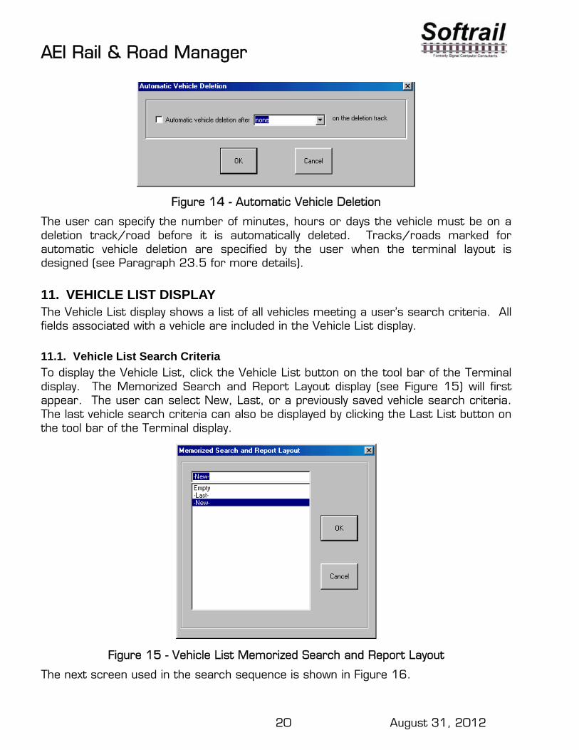
The system will automatically delete vehicles placed on a deletion track/road after a specified period of time if the user chooses the automatic vehicle deletion option. To select this option, click the Automatic Vehicle Deletion menu item under the Setup menu. Figure 14 will then be displayed.
AEI Rail & Road Manager
20 August 31, 2012
Figure 14 - Automatic Vehicle Deletion
The user can specify the number of minutes, hours or days the vehicle must be on a deletion track/road before it is automatically deleted. Tracks/roads marked for automatic vehicle deletion are specified by the user when the terminal layout is designed (see Paragraph 23.5 for more details).
11. VEHICLE LIST DISPLAY The Vehicle List display shows a list of all vehicles meeting a user’s search criteria. All fields associated with a vehicle are included in the Vehicle List display.
11.1. Vehicle List Search Criteria
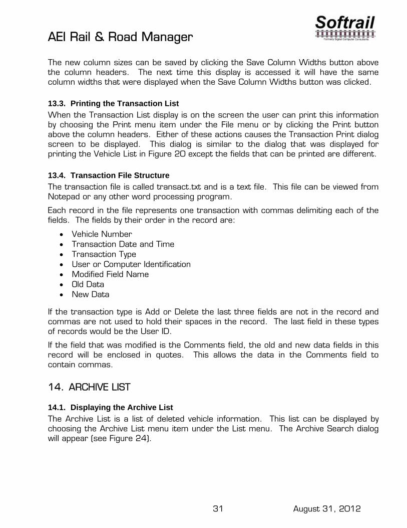
To display the Vehicle List, click the Vehicle List button on the tool bar of the Terminal display. The Memorized Search and Report Layout display (see Figure 15) will first appear. The user can select New, Last, or a previously saved vehicle search criteria. The last vehicle search criteria can also be displayed by clicking the Last List button on the tool bar of the Terminal display.
Figure 15 - Vehicle List Memorized Search and Report Layout
The next screen used in the search sequence is shown in Figure 16.

AEI Rail & Road Manager
21 August 31, 2012
Figure 16 - Vehicle List Search Criteria
If the user chooses Last or a previously saved vehicle search criteria, the algorithms of the previous search will appear on the display shown in Figure 16. If the user chooses New, he will enter the search algorithms for this new vehicle search via this display. With a few exceptions these algorithms operate in the same fashion as the user algorithms in the Vehicle Color and Status Line displays.
A time search can find all vehicles that have either entered the terminal or left the terminal during a specified span of time. The possible contents of the Time for car in facility field are either “Time in” or “Time out.” The user can specify a range of times in the From and To fields. A specific date and time can be entered into these fields or a number of hours or days before the current time. The To field also allows “now” to be entered to specify the current date and time.
If a user enters a specific date and omits the time, 12:00 AM (00:00) will be assumed in the From field and 11:59 PM (23:59) in the To field. If the year is not included, the current year is assumed.
If there is an entry in the From field, but not in the To field, the To field is assumed to be 24 hours after the value in the From field.
There are four search fields in the Vehicle Search Criteria display. With one exception these fields are logically ANDed. This means that the vehicle must meet all of the user-defined algorithms to be included in the Vehicle List display. Not meeting one algorithm’s criteria will prevent the vehicle from being included. There is only one exception to this rule. This exception is when the same field appears in more than one

AEI Rail & Road Manager
22 August 31, 2012
algorithm with an Equal to comparison. In this case the algorithms using the same field in the “Equal to” comparison will be logically ORed. If a vehicle meets only one of these algorithms’ criteria, the vehicle will be included. For example, if a user has an algorithm with the Status field equal to empty and an algorithm with the Status field equal to bad order, any vehicle having one of these two values in its Status field will be listed.
Any data can be entered into the Test field. There is a down arrow to the right of the box that, when clicked, will list all memorized values for the field. The user may choose one of these values or enter new data into the Test field.
Comparison tests are made against just the number of characters entered into the Test field. For example, if NIM is entered in the Test field for a track name, all vehicles on tracks that have names beginning with NIM will be listed. If NIM 11 is entered, only vehicles on track name NIM 11 will be listed.
The vehicles’ Comments fields can be searched for a sequence of alphanumeric characters of up to 30 characters in length. The sequence of characters being searched for can exist anywhere in a vehicle’s Comments field. The results of the search would be a list of all vehicles having the desired sequence of characters in their Comments fields.
The user can require a search of comments fields to be case sensitive. If the Case Sensitive box is checked, broken will not be considered equivalent to Broken in the comparison tests.
If the All Comments box is checked, the system will search for and list all vehicles that have comments.
By default, the system always sorts the vehicle list resulting from a search by vehicle ID in ascending alphanumeric order. In addition, the user can specify up to three sort fields. Each of these three fields can be independently sorted in ascending or descending order. The user selects the order by clicking the button on the right side of the Sort Order box (first box under each Sort Field) and clicking the appropriate entry.
Below the Sort Order box is a box for the field that is to be sorted. The user clicks the down arrow on the right side of this box to select the appropriate field to be sorted. Sort Field 1 is the highest sort level and Sort Field 3 the lowest.
To display the Vehicle List the user would then click the OK button. If the user clicks the OK button and if he or she has made changes to the search criteria, the system will first ask if the user wants to save the search criteria and give it a name so that it can be later retrieved. The vehicle list will then be displayed.
Clicking on the Cancel button, instead of the OK button, would cause the last vehicle list to be displayed.

AEI Rail & Road Manager
23 August 31, 2012
11.2. Vehicle List Display
The Vehicle List display is shown in Figure 17. The total number of vehicles found in the search is shown on the status line under the tool bar. Below the status line and a set of user buttons are the column headers followed by a list of vehicles meeting the search criteria along with user-specified information for each vehicle.
Figure 17 - Vehicle List Display
11.3. Column Widths
The user can adjust the width of the columns in this display. Place the mouse pointer on the vertical line between two column headers (for example, on the line between the Vehicle ID and Track/Train column headers), depress the left mouse key, and drag the mouse to the left or right to resize the columns.
To save the new column sizes, click the Save Column Widths button above the column headers. The next time this display is called up it will have the column widths that were displayed when this button was clicked.
11.4. Column Setup
The information displayed in the columns can be customized by the clicking the Column Setup button. This will cause the Column Order Setup display to appear (see Figure 18).
To determine the fields that will be included for each vehicle in the list, select each desired field name in the left-hand list of Available Fields and click the Add button. The field will be moved to the Selected Column Fields list. Pointing the cursor to each field and holding the control key down while clicking the left mouse button can select multiple fields.
To remove fields from the Selected Column Fields list, select the fields to be removed and click the Remove button.

AEI Rail & Road Manager
24 August 31, 2012
The fields in the Selected Column Fields list are in the same order they will appear in each line of the Vehicle List. The top field in the Selected Column Fields list will be in the left-most column of each vehicle record in the Vehicle List. Each field down the list will be in the column to the right of the previous field in the vehicle record. To change the order of the fields in the report, select the fields you want to be closer to the left side of the list and click the Advance button. The fields that are selected will move one position up the list or one column to the left in the report. You can advance any field to the top of the list and advance multiple selected fields.
Figure 18 - Vehicle List Column Order Setup Display
11.5. Vehicle Information Display
From the Vehicle List display the user can go to the Vehicle Information display for a particular vehicle by selecting the vehicle in the list and clicking on the View Data button. This will cause the Vehicle Information display for the selected vehicle to appear.
11.6. Vehicle Comments
Because comments placed in a vehicle’s Comments field can be lengthy, they are not shown on the Vehicle List display. To see the comments for a particular vehicle in a Vehicle List, select the vehicle and click the See Comments button above the column headers. The program will then display the comments associated with the selected vehicle.

AEI Rail & Road Manager
25 August 31, 2012
11.7. Finding a Vehicle on the Terminal Display
From the Vehicle List display a user can quickly jump to the location of a particular vehicle on the Terminal display. Select the vehicle in the Vehicle List and click the Find Vehicle button above the column headers. This will cause the Terminal display to appear with the mouse pointer on the desired vehicle.
11.8. Exporting Vehicle Data
Data about the listed vehicles can be exported into a delimited text file by clicking the Export Data button. See Paragraph 16 for more details.
11.9. Printing the Vehicle List
When the Vehicle List display is on the screen the user can print this information by choosing the Print menu item under the File menu or by clicking the Print button above the column headers. Either of these actions causes the screen in Figure 19 to be displayed.
Figure 19 - Vehicle List Save Print Layout
The user will select New, Last, or a previously saved print layout, and then the display in Figure 20 will appear.
The system provides the user with a great deal of flexibility in printing reports. The user can specify the report title, if line numbers and date are to be included, which fields should be in the report and in what order, the fonts used for the title, column headings and body, and the printer setup.

AEI Rail & Road Manager
26 August 31, 2012
Figure 20 - Vehicle List Print Display
The vehicle records included in the printed report will be the same records displayed in the Vehicle List on the screen. This allows the Vehicle List Search Criteria to be used to determine which vehicles will be shown in the report.
For each vehicle record included in the Vehicle List the user can choose the fields to appear in the printed report via the Vehicle List Print display shown above. Select the desired field(s) from the Available Fields list and then click on the Add button. Fields for the printed report can be chosen either individually or as a group. To select multiple fields hold the control key down while selecting the desired fields. The selected field(s) will be moved to the Selected Print Fields list after the Add button is clicked. In the screen shot above there are few fields in the Available Fields list and many fields in the Selected Print Fields list because many fields have already been selected for the printed report.
To remove fields from the Selected Print Fields list, select the fields to be removed and click the Remove button.
The fields in the Selected Print Fields list are in the same order they will appear in the printed report. The top field in the list will be in the left-most column in the report. Each field down the list will be in the column to the right of the previous field in the list. To change the order of the fields in the report, select the field(s) you want to be closer to the left side of the report and click the Advance button. The field(s) selected will move one position up the list or one column to the left in the report. Fields can be

AEI Rail & Road Manager
27 August 31, 2012
advanced either individually or as a group, and any field can be advanced to the top of the list.
By clicking the Preview button on the right side of the display you can view the report prior to printing it.
This same print display is used for printing container, transaction and archive lists.
11.10. Listing or Printing a Single Track’s Vehicle Inventory
The program has a shortcut method for generating a list or printing a list of vehicles on a single track. To start this shortcut, place the mouse cursor on the appropriate track and click the right mouse button. This causes a popup menu to appear. Select the appropriate item to start the process. See Paragraph 18 for more details.
12. PASSWORDS
12.1. Password Maintenance Dialog
The user can set up password protection for each vehicle file. To assign passwords the user chooses the Password Maintenance menu item under the Setup menu, which causes the Password Maintenance dialog to appear (see Figure 21).
Figure 21 - Password Maintenance Dialog
There are three levels of password protection that can be implemented for each vehicle file. These are: read only access, which allows the user to display vehicle database information, but not change it; read/write access, which allows the user to

AEI Rail & Road Manager
28 August 31, 2012
display and modify vehicle database information; and system access, which allows the user to modify special system facilities such as passwords and create or modify user specified fields.
To activate these various levels of protection for a given vehicle file, check the Require System Passwords and/or Require User Passwords boxes. If either of the boxes is checked and passwords are not assigned, the default system password user name is “-System-“ and the default password is “Password.” All user names and passwords are case dependent.
To add a new user simply type a user name and password into the appropriate boxes, specify the access level by checking the appropriate access level box, and click the Add button.
To edit a password, select the user name in the User Name list. The information associated with the user name will appear in the User Name and Password boxes to the right of the list. Modify the data in these boxes including the access level and click the Change button to update.
To remove a password, select the user name in the User Name list and click the Remove button.
The system will not allow you to remove the “-System-“ user name or change it. It will, however, allow you to change the password for this user name.
12.2. Password Entry
When a new vehicle file is loaded into the system, the system will check if the file requires a password before it will display the data. If a password is required, the program will ask the user to enter the user name and password. If these are valid for the vehicle file being loaded it will tell the user his or her access level and display the data.
If the user has read/write access for a vehicle file, a transaction record will be created each time the user modifies the vehicle database. This record documents the change to the record and the user who made the change. The user name that was entered with the password is the name saved with the transaction record.
12.3. Logging in a User
A user logs into the system by selecting the User Password menu item under the Setup menu. If the currently displayed vehicle file is password protected the user must have previously been assigned a password for the displayed vehicle file via the Password Maintenance dialog (see Figure 21).

AEI Rail & Road Manager
29 August 31, 2012
13. TRANSACTION LIST
13.1. Displaying the Transaction List
To display the transaction list choose the Transaction List menu item under the List menu. The Transaction Search dialog will appear (see Figure 22).
Figure 22 - Transaction Search Dialog
The user can specify a search of the transaction file for specific vehicles over a specific time period. The transaction list displayed can be sorted in either descending or ascending order by the date and time of the transaction. The display will not show more than 5000 transactions at any given time. If the user needs to see transactions that were not displayed, he or she should narrow the search criteria.
13.2. Transaction List Display
Figure 23 shows the Transaction List Display. The fields in this display include the vehicle number, type of transaction, date and time of the transaction, the user name of the user who changed the data record, the field in the data record that was changed, the old data in the field, and the new data. If the user name is unknown (because password protection is not active), the user name will be replaced with the network name of the computer.

AEI Rail & Road Manager
30 August 31, 2012
Figure 23 - Transaction List
There are three types of transactions. These are Add, Delete and Modify. The Add type indicates that the vehicle was added to the database. After a vehicle is added to the database a number of the fields are automatically updated which causes a number of Modify type records to be automatically generated. If the vehicle is added by a user with the manual Add a Vehicle command, the user’s name will be in the User ID field of the vehicle record. If no password protection is assigned to the vehicle file and a user name is not entered, the User ID will be shown as Unknown. If the added record is generated by input from an AEI reader, the name of the reader site that added the vehicle will be in User ID field.
When a new vehicle is added to the vehicle database, the user can specify default values for some of the fields. If a default value is used for a field, the User ID will be shown as Default.
The user can ask the system to search the archive file for information on a vehicle. If the archive file contains information on the vehicle, the user can specify which fields in the archive file should be used to update fields in the new record on the vehicle. In this case Restored will be shown as the User ID. See Paragraph 15.
The Comments field can be as long as 200 characters. If the transaction record is due to a modification to the Comments field, the user must click the See Comments button after selecting the appropriate record.
The width of the columns in this display can be adjusted by placing the mouse pointer on the vertical line between two column headers (for example on the line between the Vehicle ID and Type column headers), depressing the left mouse key, and dragging the mouse to the left or right to resize the columns.
AEI Rail & Road Manager
31 August 31, 2012
The new column sizes can be saved by clicking the Save Column Widths button above the column headers. The next time this display is accessed it will have the same column widths that were displayed when the Save Column Widths button was clicked.
13.3. Printing the Transaction List
When the Transaction List display is on the screen the user can print this information by choosing the Print menu item under the File menu or by clicking the Print button above the column headers. Either of these actions causes the Transaction Print dialog screen to be displayed. This dialog is similar to the dialog that was displayed for printing the Vehicle List in Figure 20 except the fields that can be printed are different.
13.4. Transaction File Structure
The transaction file is called transact.txt and is a text file. This file can be viewed from Notepad or any other word processing program.
Each record in the file represents one transaction with commas delimiting each of the fields. The fields by their order in the record are:
Vehicle Number Transaction Date and Time Transaction Type User or Computer Identification Modified Field Name Old Data New Data
If the transaction type is Add or Delete the last three fields are not in the record and commas are not used to hold their spaces in the record. The last field in these types of records would be the User ID.
If the field that was modified is the Comments field, the old and new data fields in this record will be enclosed in quotes. This allows the data in the Comments field to contain commas.
14. ARCHIVE LIST
14.1. Displaying the Archive List
The Archive List is a list of deleted vehicle information. This list can be displayed by choosing the Archive List menu item under the List menu. The Archive Search dialog will appear (see Figure 24).

AEI Rail & Road Manager
32 August 31, 2012
Figure 24 - Archive Search Dialog
The archive file contains the records of vehicles deleted from the system. The user can specify a search of the archive file for specific vehicles over a specific time period. The deletion records displayed can be sorted in either descending or ascending order by the date and time the deletion took place. The display will not show more than 5000 records at any given time. If the user needs to see records that are not displayed, he or she should narrow the search criteria.
14.2. Archive List Display
Figure 25 shows the Archive List display. Each entry in this list contains all of the fields in the vehicle record at the time the vehicle was deleted from the system, the date and time the vehicle was deleted, and the user identification of who deleted the record.
Figure 25 - Archive List Display
The Comments field can be as long as 200 characters. If the deleted vehicle record has information in its Comments field, to display this field the user must click the See Comments button after selecting the appropriate record.

AEI Rail & Road Manager
33 August 31, 2012
The user can adjust the width of the columns in this display. Place the mouse pointer on the vertical line between two column headers (for example, on the line between the Vehicle ID and Delete Date/Time column headers), depress the left mouse key and drag the mouse to the left or right to resize the columns.
The new column sizes can be saved by clicking on the Save Column Widths button above the column headers. The next time this display is accessed it will have the same column widths that were displayed when the Save Column Widths button was clicked.
14.3. Restoring a Deleted Vehicle
The user can restore a deleted vehicle to the Terminal display by selecting the vehicle record from the Archive List display and clicking the Restore Vehicle button.
14.4. Printing the Archive List
When the Archive List display is on the screen the user can print this information by choosing the Print menu item under the File menu or by clicking the Print button above the column headers. Either of these actions causes an Archive Print Dialog screen to be displayed. This dialog is similar to the dialog that was displayed for printing the Vehicle List in Figure 20 except the fields that can be printed are different.
14.5. Archive File Structure
The archive file is called archive.txt and is a text file. This file can be viewed from Notepad or any other word processing program.
Each record in the file represents one vehicle deletion record with commas delimiting each of the fields. The fields by their order in the record are:
Deletion Date and Time Vehicle Number User or Computer Identification Status Consist Vehicle Type The Seven User Defined Fields Comments
15. RESTORE FIELDS When a new vehicle is added, either manually by a user or automatically by an AEI reader, the system searches the archive file for the most recent record for that vehicle. If the vehicle was entered previously, the system will update the new vehicle’s record from the last information it found on the vehicle. The user can specify which fields he or she wants to be automatically updated. This feature can be very helpful, for example, when the user stores the vehicle’s tare weight in the vehicle’s record.
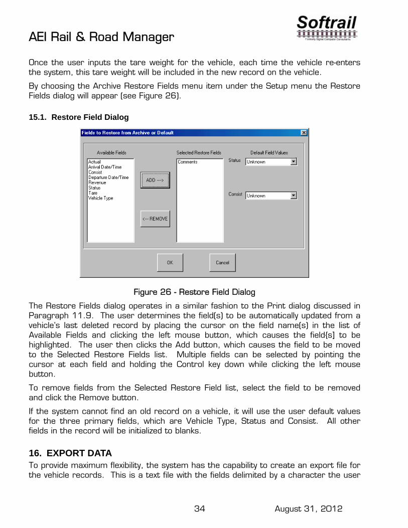
AEI Rail & Road Manager
34 August 31, 2012
Once the user inputs the tare weight for the vehicle, each time the vehicle re-enters the system, this tare weight will be included in the new record on the vehicle.
By choosing the Archive Restore Fields menu item under the Setup menu the Restore Fields dialog will appear (see Figure 26).
15.1. Restore Field Dialog
Figure 26 - Restore Field Dialog
The Restore Fields dialog operates in a similar fashion to the Print dialog discussed in Paragraph 11.9. The user determines the field(s) to be automatically updated from a vehicle’s last deleted record by placing the cursor on the field name(s) in the list of Available Fields and clicking the left mouse button, which causes the field{s] to be highlighted. The user then clicks the Add button, which causes the field to be moved to the Selected Restore Fields list. Multiple fields can be selected by pointing the cursor at each field and holding the Control key down while clicking the left mouse button.
To remove fields from the Selected Restore Field list, select the field to be removed and click the Remove button.
If the system cannot find an old record on a vehicle, it will use the user default values for the three primary fields, which are Vehicle Type, Status and Consist. All other fields in the record will be initialized to blanks.
16. EXPORT DATA To provide maximum flexibility, the system has the capability to create an export file for the vehicle records. This is a text file with the fields delimited by a character the user

AEI Rail & Road Manager
35 August 31, 2012
can choose. The user can also choose which fields will be included in each export record. With this capability the information in the system can be easily transferred to various commercial word processing, spreadsheet or database programs or to user-written programs allowing the user to generate special reports and perform statistical analyses.
By choosing the Export menu item under the File menu the Export Fields dialog will appear and ask for the Export file name.
16.1. Export Dialog
Once the name is entered, the display shown in Figure 27 will appear. The user can specify a one-character delimiter (usually a comma or a space), which will be placed between each field in the records. The user can also specify if the first record of the file will contain the names of the fields in the order they appear in each of the vehicle records to be exported. The last option before selecting the fields to be included in the export record concerns whether all of the vehicles’ records will be included in the export file, or just the ones found in the last Vehicle List Search.
Figure 27 - Export Dialog
The user then selects the fields to be included in each vehicle’s export record as was done with the Print dialog described in Paragraph 9.5. The user determines what fields will be included in each export record by placing the cursor on each desired field's name in the left hand list of Available Fields and clicking the left mouse button. This causes the field to be highlighted. The user then clicks the Add button, which

AEI Rail & Road Manager
36 August 31, 2012
moves it to the Selected Export Fields list. Multiple fields can be selected by pointing the cursor at each field and holding the Control key down while clicking the left mouse button.
To remove fields from the Selected Export Fields list, select the field to be removed and click the Remove button.
The fields in the Selected Export Fields list are in the order in which they will be listed in each export vehicle record. The top field in the list will be the first field. Each field down the list will be the next field in the export record. To move a field or fields closer to the beginning of the record, select the field(s) and click the Advance button. Multiple fields can be selected as has been described above. The field(s) selected will move one position up the list or one field closer to the beginning of the record.
16.2. Export Vehicle Inventory on a Single Track/Road
The program has a shortcut method for exporting a single track/road’s vehicle inventory. To start this shortcut place the mouse cursor on the appropriate track/road on the Terminal display and click the right mouse button. This causes a popup menu shown in Figure 28 to appear. Select the appropriate item to start the process.
17. REVERSE TRACK INVENTORY To reverse the order in which vehicles are displayed on a track (flip a track’s inventory making the left most vehicle, the right most vehicle, etc.), place the mouse cursor on the track to be reversed and click the right mouse button. This will cause a pop-up menu (see Figure 28) to display. Click the Reverse track consist item to flip the track’s inventory.
18. SUMMARY OF TRACK/ROAD SHORTCUT FUNCTIONS In summary, the system provides easy shortcut methods for exporting, listing, printing, reversing inventory or deleting vehicles on a track. To implement any of these shortcut functions, place the mouse cursor on the track for which the function is desired and click the right mouse button. The pop-up menu in Figure 28 will appear.

AEI Rail & Road Manager
37 August 31, 2012
Figure 28 - Shortcut Pop-up Menu
Click the appropriate item to begin the dialog for a function. The functions are described in the paragraphs listed below:
Exporting Track Inventory – Paragraph 16 Listing Track Inventory - Paragraph 11.2 Printing Track Inventory - Paragraph 11.9 Reversing Track Inventory - Paragraph 17 Deleting Track Inventory - Paragraph 10.1
19. FILE MAINTENANCE There are three major files that should be maintained. These are the Vehicle Data file, the Transaction file, and the Archive Delete file.
19.1. Manual File Backup
To manually backup the Vehicle Data, Transaction or Archive Delete files, select the appropriate back-up menu item under the File menu. The Vehicle Data file that will be backed up is the file that is currently being displayed. All back-up files are given the .bak extension unless the user specifies another extension.
19.2. Automatic Backup of Vehicle Data File
The system can automatically make back-up copies of the Vehicle Data file via the display shown in Figure 29. Select the File Maintenance menu item under the Setup menu to bring this screen up.
The user can specify whether the Vehicle Data file should be automatically backed up, how often, and the required number of back-up copies. The time can be specified in

AEI Rail & Road Manager
38 August 31, 2012
minutes, hours, or days. The system will make a new back-up copy unless the file has not changed since the last back-up copy was made.
The system will maintain up to 99 back-up copies for the user. These back-up copies will have a file extension of .bxx. The xx portion of the extension is a number from 01 to 99. The file extension of .b01 is given to the latest back-up copy and .b99 would be the oldest if the user specified that 99 back-up copies should be maintained.
Figure 29 - File Maintenance
19.3. Automatic Deletion of Transaction Records
The user can also specify via the File Maintenance screen (see Figure 29) whether transaction records should be automatically deleted. The records to be deleted can be determined by either the size of the file and/or the date of the record. The user specifies the maximum size of the file in 1,000 byte increments. Periodically the system will check if the file is larger than the maximum size and delete only the oldest records in the file to reduce the file’s size to just below the maximum size.
The user can also specify automatic deletion of records older than a user-specified period of time. The specified period can be in minutes, hours, days, or months from the current date and time. Periodically the system will check each transaction record’s transaction date and time and delete records older than the user specified criteria.
If the user selects the maximum size and transaction age deletion criteria, the system will first perform the maximum size deletions and then the transaction age deletions.

AEI Rail & Road Manager
39 August 31, 2012
19.4. Automatic Deletion of Communication Records
The system maintains communication logs for each of the four communication ports (comm ports) that are used to communicate with AEI readers (see Paragraph 26.3 for more information). These logs are kept in files named comport1.txt, comport2.txt, comport3.txt and comport4.txt. All communications between the system and AEI readers can be found in these logs, including the time each communication record was generated. The user can view these records by using any standard text or word processing software such as Notepad or Word.
The user can also specify via the File Maintenance screen (see Figure 29) whether communication records should be automatically deleted by file size and/or the age of the communication record in the same fashion as the Automatic Deletion of Transaction Records in Paragraph 19.3.
19.5. Network File Maintenance Manager
In single user systems, the computer that maintains the files is the same computer that runs AEI Rail & Road Manager. In multi-user systems only one of the computers that runs AEI Rail & Road Manager can be assigned as the File Maintenance Manager.
To assign a computer as the File Maintenance Manager select the Setup/File Maintenance Manager Selection item. The dialog in Figure 30 will appear.
Figure 30 - File Maintenance Manager Selection
Softrail will provide the system administrator with a code to turn this function on. To turn this function off select the Setup/File Maintenance Manager Selection menu item again.
20. MAINTENANCE LOG FILE AEI Rail & Road Manager maintains a maintenance log file called "maint log.txt". This file is used to help diagnose problems with the system. It can be viewed by selecting the AEI/Maintenance Log menu item.

AEI Rail & Road Manager
40 August 31, 2012
Figure 31 - Maintenance Log
21. MEMORIZED LIST MAINTENANCE Each time the user enters a value into a field such as Consist or Status the program memorizes the new value and stores it in a list of possible values for the field. This list will appear any time the user selects the field for input or as part of a search. To make modifications to this list select the Memorized List Maintenance menu item under the Setup menu. The display shown in Figure 25 will appear.

AEI Rail & Road Manager
41 August 31, 2012
Figure 32 - Memorized Lists
To add, delete or modify an item in a field’s list, select the field in the left list box by clicking the left mouse button on the item. To add an entry, type the new data in the Edit Field box and click the Add button. To delete at item, select the item in the right list box (this item will now appear in the Edit Field) and click the Remove button. To modify an item, select the item in the right list box, change the data in the Edit Field and click the Change button.
The Memorized List Maintenance dialog also allows the user to delete or change the names of previously stored search criteria (see Paragraph 11.1) and print report layouts (see Paragraph 11.9).
22. UMLER DATABASE The association of American Railroads maintains a rail equipment database called UMLER (Universal Machine Language Equipment Register). AEI Rail & Road Manager is designed to interface with a subset of the UMLER database. This subset consists of the following information for all vehicles registered in UMLER:
Vehicle type Coupler to coupler length Number of axles Bearing code Number of platforms

AEI Rail & Road Manager
42 August 31, 2012
Tare weight Capacity weight
When vehicles are entered into this program’s database either by manual entry or by a tag read from a wayside or portable reader, the system automatically searches UMLER to find a record on the vehicle. If a record is found, the vehicle type determines the graphical representation of the vehicle on the Terminal display. Users can also view the other UMLER data fields in the vehicle record by calling up Figure 8.
In order for the system to use UMLER information, the UMLER database subset must be loaded into the system and is available on CD from Softrail. Because UMLER is constantly being updated, Softrail plans to create a new UMLER database subset CD each month and distribute to customers on a subscription basis. To obtain more information about this service, contact Softrail.
22.1. Loading the UMLER Database from a CD
The UMLER data is loaded by inserting the UMLER Database CD into the system’s CD drive and selecting the Load UMLER CD Data item from the File menu. Subsequently opening the file “Umler.txt” on the CD expands and transfers the database to the system’s hard drive.
22.2. Searching for Vehicle UMLER Data
The system allows users to search the internal UMLER database subset for a particular vehicle's data. To find a vehicle’s UMLER data select the Find UMLER Data item under the Tools menu, enter the vehicle initials and number in the dialog boxes, and click the Find button. If the vehicle record is found, the data will be displayed as shown in Figure 33.
Figure 33 - Find UMLER Data
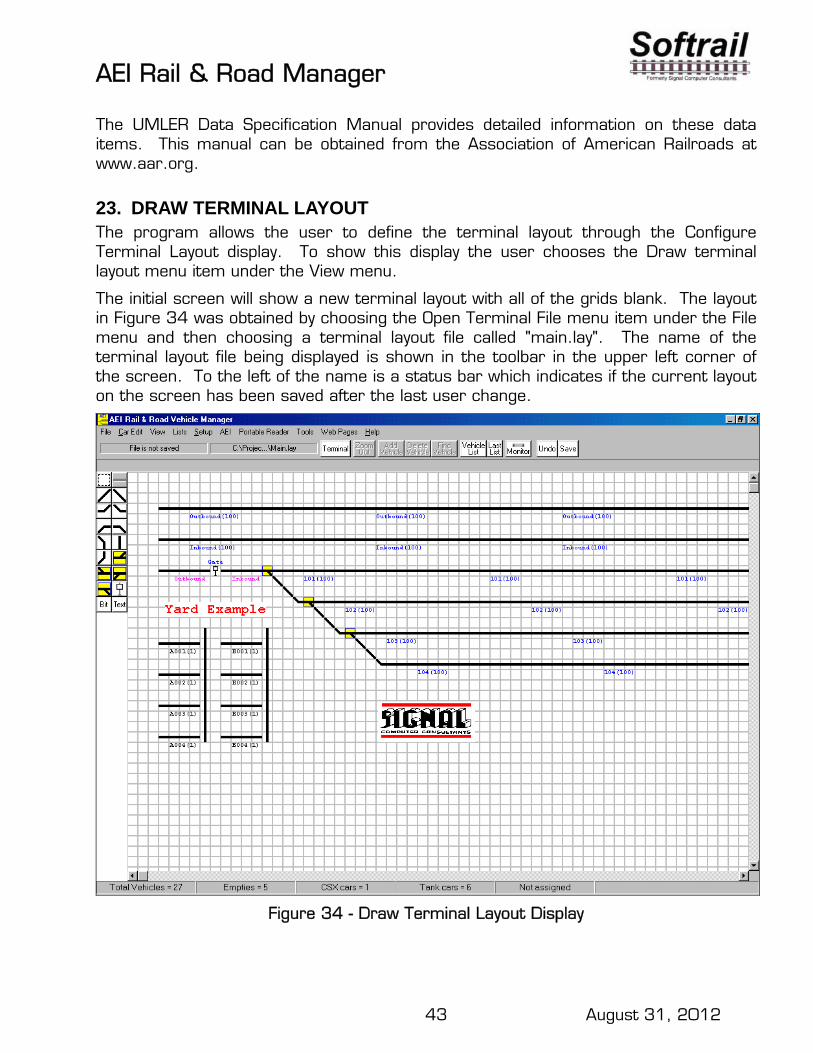
AEI Rail & Road Manager
43 August 31, 2012
The UMLER Data Specification Manual provides detailed information on these data items. This manual can be obtained from the Association of American Railroads at www.aar.org.
23. DRAW TERMINAL LAYOUT The program allows the user to define the terminal layout through the Configure Terminal Layout display. To show this display the user chooses the Draw terminal layout menu item under the View menu.
The initial screen will show a new terminal layout with all of the grids blank. The layout in Figure 34 was obtained by choosing the Open Terminal File menu item under the File menu and then choosing a terminal layout file called "main.lay". The name of the terminal layout file being displayed is shown in the toolbar in the upper left corner of the screen. To the left of the name is a status bar which indicates if the current layout on the screen has been saved after the last user change.
Figure 34 - Draw Terminal Layout Display
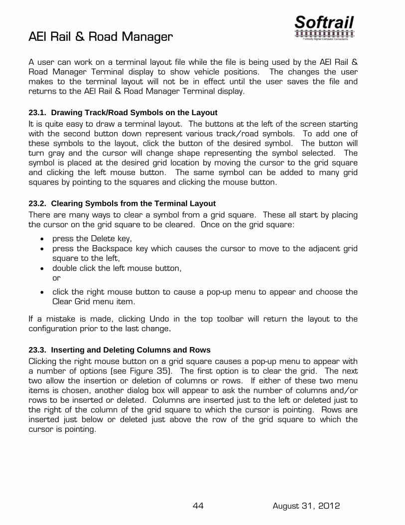
AEI Rail & Road Manager
44 August 31, 2012
A user can work on a terminal layout file while the file is being used by the AEI Rail & Road Manager Terminal display to show vehicle positions. The changes the user makes to the terminal layout will not be in effect until the user saves the file and returns to the AEI Rail & Road Manager Terminal display.
23.1. Drawing Track/Road Symbols on the Layout
It is quite easy to draw a terminal layout. The buttons at the left of the screen starting with the second button down represent various track/road symbols. To add one of these symbols to the layout, click the button of the desired symbol. The button will turn gray and the cursor will change shape representing the symbol selected. The symbol is placed at the desired grid location by moving the cursor to the grid square and clicking the left mouse button. The same symbol can be added to many grid squares by pointing to the squares and clicking the mouse button.
23.2. Clearing Symbols from the Terminal Layout
There are many ways to clear a symbol from a grid square. These all start by placing the cursor on the grid square to be cleared. Once on the grid square:
press the Delete key, press the Backspace key which causes the cursor to move to the adjacent grid
square to the left, double click the left mouse button,
or
click the right mouse button to cause a pop-up menu to appear and choose the Clear Grid menu item.
If a mistake is made, clicking Undo in the top toolbar will return the layout to the configuration prior to the last change.
23.3. Inserting and Deleting Columns and Rows
Clicking the right mouse button on a grid square causes a pop-up menu to appear with a number of options (see Figure 35). The first option is to clear the grid. The next two allow the insertion or deletion of columns or rows. If either of these two menu items is chosen, another dialog box will appear to ask the number of columns and/or rows to be inserted or deleted. Columns are inserted just to the left or deleted just to the right of the column of the grid square to which the cursor is pointing. Rows are inserted just below or deleted just above the row of the grid square to which the cursor is pointing.

AEI Rail & Road Manager
45 August 31, 2012
Figure 35 - Draw Terminal Layout Pop-up Menu
23.4. Duplicating Straight Track/Road Symbols
To make it easier to draw long track/road lines, the pop-up menu shown in Figure 35 so may have a Duplicate menu item. This menu item only appears if the cursor is pointing to a grid square that displays a straight track/road symbol. By selecting this menu item another dialog box appears which asks for the number of times the symbol is to be duplicated. These duplicates are placed to the right of the grid square to which the cursor is pointing.
Vehicle symbols on the Terminal display require four grid squares each. To display twenty vehicles on a track, eighty grid squares are required. The system will store up to 100 vehicles on a track, but will only display the vehicles it can physically fit on the track/road in the Terminal display. For example, if the track/road can only display 20 vehicles, the vehicles in the first twenty positions from the left end of the track/road will be displayed even though there may be up to one hundred vehicles assigned to that track. If any one of the first twenty vehicles is moved to another track, the twenty-first vehicle in the original list will appear in the twentieth position on the track.
23.5. Track/Road Names
The system will only allow vehicles to be placed on tracks/roads that have been assigned names. A vehicle’s location is stored as the name of the track/road it is on with its position from the left end of the track/road. To assign a name to a track/road click the right mouse button on a grid square containing the track/road and choose the Properties menu item in the pop-up menu. This causes the Track/Road Information dialog to appear (see Figure 36).
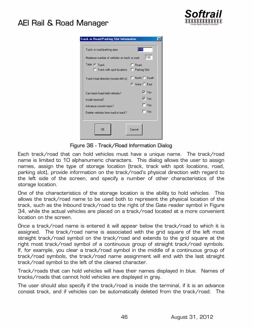
AEI Rail & Road Manager
46 August 31, 2012
Figure 36 - Track/Road Information Dialog
Each track/road that can hold vehicles must have a unique name. The track/road name is limited to 10 alphanumeric characters. This dialog allows the user to assign names, assign the type of storage location (track, track with spot locations, road, parking slot), provide information on the track/road’s physical direction with regard to the left side of the screen, and specify a number of other characteristics of the storage location.
One of the characteristics of the storage location is the ability to hold vehicles. This allows the track/road name to be used both to represent the physical location of the track, such as the Inbound track/road to the right of the Gate reader symbol in Figure 34, while the actual vehicles are placed on a track/road located at a more convenient location on the screen.
Once a track/road name is entered it will appear below the track/road to which it is assigned. The track/road name is associated with the grid square of the left most straight track/road symbol on the track/road and extends to the grid square at the right most track/road symbol of a continuous group of straight track/road symbols. If, for example, you clear a track/road symbol in the middle of a continuous group of track/road symbols, the track/road name assignment will end with the last straight track/road symbol to the left of the cleared character.
Track/roads that can hold vehicles will have their names displayed in blue. Names of tracks/roads that cannot hold vehicles are displayed in gray.
The user should also specify if the track/road is inside the terminal, if it is an advance consist track, and if vehicles can be automatically deleted from the track/road. The

AEI Rail & Road Manager
47 August 31, 2012
“inside the terminal” designation is used in conjunction with AEI readers to determine values in the Time In field. The first time an AEI reader automatically adds a vehicle to a track/road that is designated as being in the terminal, it automatically updates the vehicle’s Time In field with the tag read time. This field is used to perform limited vehicle data searches on vehicles within or outside of the terminal.
The “advance consist track” designation is used in conjunction with vehicle information the system receives in EDI 417 and EDI 418 messages.
The system can automatically delete vehicles after a user specified time period on the track/road (see Paragraph 10.5], but only from tracks that allow automatic vehicle deletion. The dialog shown is Figure 36 is also used to specify whether or not automatic vehicle deletion is allowed on the track/road being named.
23.6. AEI Reader Site Information
The symbol near the bottom right of the left hand tool bar (see Figure 34) represents an AEI reader site. Each active reader site must be named and have track/road names associated with it. To display the Reader Site Setup dialog (see Figure 37), position the cursor on the appropriate grid square containing the reader symbol, click the right mouse button, and choose the Properties menu.
Figure 37 - Reader Site Setup Dialog
Each active reader site must have a unique name and have valid right and left track/road names. These track/road names must be assigned in the Track/Road Information dialog before they can be used in the Reader Site Setup dialog.

AEI Rail & Road Manager
48 August 31, 2012
The user can specify if the next vehicle read is placed on the left end or right end of the track/road. Normally vehicles placed on a track/road to the right of the reader are positioned at the left end of the track/road, and vehicles read to a track/road to the left of the reader are positioned at the right end of the track/road.
The user can also specify if the reader will automatically move rail vehicles that are already on a track in the terminal. This option is used to prevent rail vehicles from losing their manually assigned track location if they are involved in a switching operation that passes the reader.
23.7. Selecting a Group of Grid Squares
To make it easier to configure the terminal layout, the user can select several grid squares which can be moved or cleared as an intact group. The left-most top button in the left-hand tool bar is used to select a group of squares. When this button is clicked the cursor will turn to cross hairs when it is moved over the grid. To select a group of grid squares, place the cursor in the grid square just above and to the left of the top, left-most square to be selected, hold down the left mouse button, and drag the cursor to the grid square just below and to the right of the group to be selected. While dragging the cursor, a blue rectangle will appear which encompasses the selected squares. When the left mouse button is released the selected squares will become light blue.
Figure 38 - Selected Group of Grid Squares

AEI Rail & Road Manager
49 August 31, 2012
23.7.1. Clearing a Selected Group of Squares
To clear all of the squares in this group, place the cursor on any square in the group and perform one of the following:
press the Delete key, double click the left mouse button
or click the right button to cause a pop-up menu to appear, and choose the Clear
Grid menu item.
If a mistake is made, clicking Undo in the top toolbar will return the layout to the configuration prior to the last change.
23.7.2. Moving a Selected Group Of Squares
To move the selected group to another location on the grid, place the cursor on any grid square in the selected group, hold the left mouse down and drag the group to another location. A blue rectangle equal to the size of the selected group will appear and move with the cursor. When the left mouse button is released the selected group will move to the new location, but will not change any symbols underneath the selected group until the group of squares in deselected. This feature allows the user to move the selected group again without affecting the grid squares it overlaid. Once deselected, the symbols the group overlaid will be replaced by the symbols in the selected group. Again, the Undo button can always be used to return the display to its configuration before the group was selected.
If the first straight track/road symbol in a named track/road is moved as part of this selected group, the track/road name will move with the symbol. The track/road name will disappear from the remaining straight track/road symbols that were not moved.
To deselect a group, place the cursor on any grid square outside of the selected group and click the left mouse button.
23.7.3. Using a Selected Group of Squares to Insert and Delete Columns and Rows
The selecting of a group of squares also allows more flexibility with the use of the insert and delete columns and rows functions in the pop-up menu. For example, if a group of grid squares is selected that is one column wide and three rows long and a single column is inserted, the column will only be inserted in the rows that were in the selected group of grid squares (see Figure 39). The same is true for inserting rows. The rows will only be inserted in the selected columns.

AEI Rail & Road Manager
50 August 31, 2012
Figure 39 - Using a Group of Selected Squares to Insert Columns
23.8. Bitmaps (User Generated Graphics)
The users can add their own graphics to the Terminal Layout Display. These graphics are in the form of bitmaps, which can be copied from a variety of sources such as Clip Art packages, or generated by the user using software such as Paint. These bitmaps may represent the user company’s logo or physical items at the user’s facility such as buildings, roads, rivers, etc.
All bitmap files have a file extension of .bmp. The system limits a single bitmap size to 60,000 bytes and the number of colors to 16. The user may generate a number of bitmaps (see Paragraph 31 for the maximum number of bitmaps).
Any bitmap can be used many times and resized when inserted in the Terminal Layout Display.
23.8.1. Adding Bitmaps
The user adds bitmaps by first clicking the bitmap symbol button on the left hand side of the screen, moving the cursor to the intended location in the Terminal Layout Display grid, and clicking the left mouse button. Figure 40 will then be displayed.

AEI Rail & Road Manager
51 August 31, 2012
Figure 40 - Inserting a Bitmap
A list of available bitmaps appears in the Bitmap Description list box on the left-hand side of the display. Each Terminal Layout file maintains its own unique list of available bitmaps. For example, a new Terminal Layout file will not have any bitmaps until the user adds a bitmap to the file by use of the Bitmap Maintenance function. This function can be called by clicking the Bitmap Maintenance button on this screen.
This display shows the bitmap’s original width and height in pixels. The user can change the size of the bitmap that is displayed on the Terminal Layout by changing the number of pixels in the Current Width and Height fields. The user can make the displayed bitmap larger or smaller than the original.
Bitmaps can be displayed in the background or foreground. If in the background, all track/road and vehicle symbols will be displayed on top of the background bitmaps. If the user specifies the bitmap to be in the foreground, the bitmap will be written on top of the track/road and vehicle symbols. Foreground bitmaps also are written on top of background bitmaps and background user text areas (see Paragraph 23.10 for more information). Figure 41 shows the effect of adding a foreground bitmap to the Terminal Layout. This bitmap is displayed in its original size.

AEI Rail & Road Manager
52 August 31, 2012
Figure 41 - Foreground Bitmap
23.8.2. Modifying Bitmaps
Bitmaps already displayed can be easily moved, deleted, resized or duplicated. To perform any of these operations the displayed bitmap must first be selected. To select a particular bitmap, first click the bitmap symbol on the left-hand side of the display and then point to the bitmap to be modified. The cursor will change in shape from the bitmap symbol to an arrow.
23.8.2.1. Moving Bitmaps
Once selected, move the bitmap by holding down the left mouse button, which causes a blue rectangle around the bitmap, and drag the bitmap to another position on the screen. If the bitmap is dragged near the edge of the screen, the screen will automatically scroll in the direction of the cursor movement.
23.8.2.2. Deleting Bitmaps
There are three ways to delete a bitmap: select the bitmap and then press the Delete key; double click the left mouse button; or click the right mouse button. The first two operations will immediately delete the bitmap from the display. The last operation (click the right mouse button) will cause a secondary menu to appear (see Figure 42). Click the Delete Bitmap menu item to delete the bitmap.
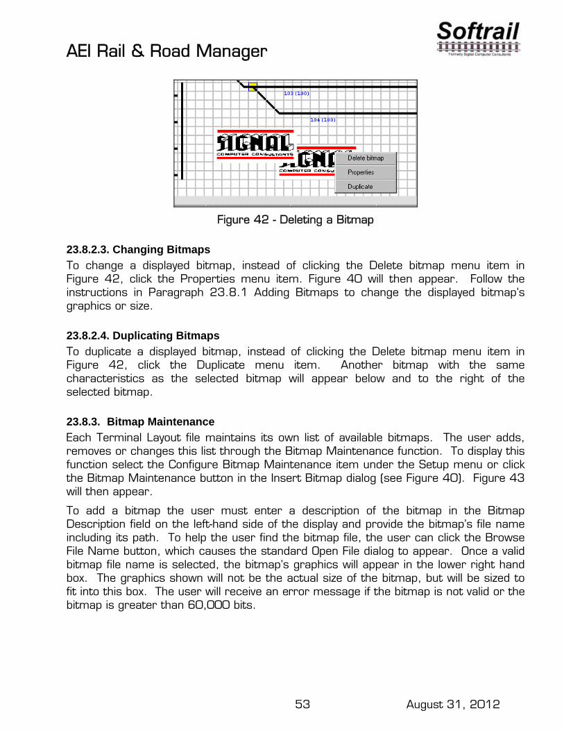
AEI Rail & Road Manager
53 August 31, 2012
Figure 42 - Deleting a Bitmap
23.8.2.3. Changing Bitmaps
To change a displayed bitmap, instead of clicking the Delete bitmap menu item in Figure 42, click the Properties menu item. Figure 40 will then appear. Follow the instructions in Paragraph 23.8.1 Adding Bitmaps to change the displayed bitmap’s graphics or size.
23.8.2.4. Duplicating Bitmaps
To duplicate a displayed bitmap, instead of clicking the Delete bitmap menu item in Figure 42, click the Duplicate menu item. Another bitmap with the same characteristics as the selected bitmap will appear below and to the right of the selected bitmap.
23.8.3. Bitmap Maintenance
Each Terminal Layout file maintains its own list of available bitmaps. The user adds, removes or changes this list through the Bitmap Maintenance function. To display this function select the Configure Bitmap Maintenance item under the Setup menu or click the Bitmap Maintenance button in the Insert Bitmap dialog (see Figure 40). Figure 43 will then appear.
To add a bitmap the user must enter a description of the bitmap in the Bitmap Description field on the left-hand side of the display and provide the bitmap’s file name including its path. To help the user find the bitmap file, the user can click the Browse File Name button, which causes the standard Open File dialog to appear. Once a valid bitmap file name is selected, the bitmap’s graphics will appear in the lower right hand box. The graphics shown will not be the actual size of the bitmap, but will be sized to fit into this box. The user will receive an error message if the bitmap is not valid or the bitmap is greater than 60,000 bits.

AEI Rail & Road Manager
54 August 31, 2012
Figure 43 - Bitmap Maintenance
To add this bitmap to the Terminal Layout file click the Add button. Once added, the description the user entered for the bitmap will appear in the Bitmap Description list box on the left-hand side of the display.
To remove or change a bitmap in the Terminal Layout file, select the bitmap description in the Bitmap Description list box by pointing the cursor at it and clicking the left mouse button. The user can then remove it by clicking the Remove button or change the description or file name by clicking the Change button.
23.9. User Text Areas
The user can add text to the Terminal Layout display. The user specifies the font, font size and color of the text. The user may generate a number of text areas (see Paragraph 31 for the maximum number of text areas).
23.9.1. Adding Text Areas
The user adds text by clicking on the Text button in the vertical tool bar, pointing the cursor at the location in the Terminal Layout Display grid where the text is to be placed, and then clicking the left mouse button. Figure 44 will then be displayed.

AEI Rail & Road Manager
55 August 31, 2012
Figure 44 - Inserting Text
To add text the user types the text in the Text box on the left-hand side of the screen. The system creates a text box that is sized for the amount of text the user entered for the given font and font size. The user can specify whether the text is to be left, center or right justified by clicking the appropriate button (Left Text, Center Text or Right Text). The user can also specify whether the text box will have a border around it by checking the Border box.
If the user wants to change the text’s font, font size or font style, the user will click the Font button, and the standard Font dialog will appear.
To change the text color the user clicks the Color button, and the standard Color dialog will appear (see Figure 45). The user then clicks on one of the color boxes for the color he or she wants to use for the text.
Figure 45 - Color Dialog

AEI Rail & Road Manager
56 August 31, 2012
Text areas can be displayed in the background or foreground. If in the background, all track/road and vehicle symbols will be displayed on top of the background text areas. If the user specifies the text area to be in the foreground, the text area will be written on top of the track/road and vehicle symbols. Foreground text areas also are written on top of background bitmaps and background user text areas (see Paragraph 23.10 for more information). Figure 46 shows the effect of adding a foreground text area to the Terminal Layout.
Figure 46 - Foreground Text Area
23.9.2. Modifying Text
Text areas displayed on the Terminal Layout Display can be easily moved, deleted, changed or duplicated. To perform any of these operations the text area must first be selected. To select a particular text area, first click on the Text button in the vertical tool bar and then point to the text area that you want to modify. As soon as you point to a text area, the cursor will change in shape from the Text symbol to an arrow.
23.9.2.1.Moving Text Areas
To move a text area point to the text area, then hold down the left mouse button, which will cause a blue rectangle to appear around the text area. While holding the left button down drag the text area to another position on the screen. If the text area is dragged near the edge of the screen, the screen will automatically scroll in the direction of the cursor movement.
23.9.2.2.Deleting Text Areas
After selection there are three ways to delete a text area: press the Delete key; double click the left mouse button; or click the right mouse button. The first two operations will immediately delete the text area from the display. The last operation (click the right mouse button) will cause a secondary menu to appear (see Figure 47). Click the Delete Text menu item to delete the text.
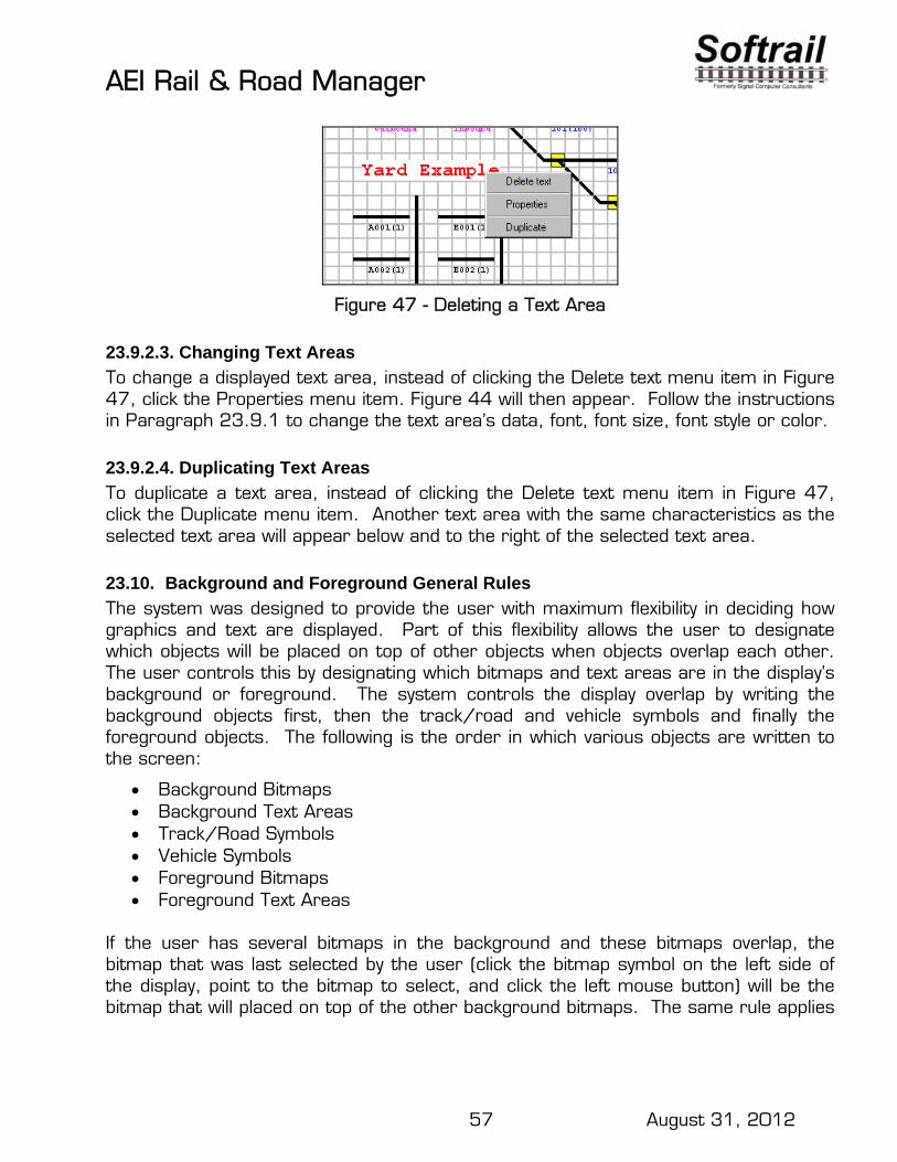
AEI Rail & Road Manager
57 August 31, 2012
Figure 47 - Deleting a Text Area
23.9.2.3. Changing Text Areas
To change a displayed text area, instead of clicking the Delete text menu item in Figure 47, click the Properties menu item. Figure 44 will then appear. Follow the instructions in Paragraph 23.9.1 to change the text area’s data, font, font size, font style or color.
23.9.2.4. Duplicating Text Areas
To duplicate a text area, instead of clicking the Delete text menu item in Figure 47, click the Duplicate menu item. Another text area with the same characteristics as the selected text area will appear below and to the right of the selected text area.
23.10. Background and Foreground General Rules
The system was designed to provide the user with maximum flexibility in deciding how graphics and text are displayed. Part of this flexibility allows the user to designate which objects will be placed on top of other objects when objects overlap each other. The user controls this by designating which bitmaps and text areas are in the display’s background or foreground. The system controls the display overlap by writing the background objects first, then the track/road and vehicle symbols and finally the foreground objects. The following is the order in which various objects are written to the screen:
Background Bitmaps Background Text Areas Track/Road Symbols Vehicle Symbols Foreground Bitmaps Foreground Text Areas
If the user has several bitmaps in the background and these bitmaps overlap, the bitmap that was last selected by the user (click the bitmap symbol on the left side of the display, point to the bitmap to select, and click the left mouse button) will be the bitmap that will placed on top of the other background bitmaps. The same rule applies

AEI Rail & Road Manager
58 August 31, 2012
to two foreground bitmaps or two text areas that are either both in the background or foreground.
23.11. Saving a Terminal Layout File
To save a terminal layout file choose Save Layout File under the File menu. The new terminal layout cannot be used in the Terminal display until it has been saved.
23.12. Password Protection
When the terminal layout file is saved the system will ask if password protection is required. A password can be assigned to prevent unauthorized changes to this file. While working on the terminal layout file, the file’s password dialog can be accessed by choosing Password Maintenance under the Setup menu.
23.13. General Drawing Guidelines
The system will not prevent conflicts in the display of track/road symbols, track/road and reader names, and vehicle symbols. The vehicle symbols are the last items displayed on the screen and will write over any other items on the screen at the same location. If possible, a minimum of three grid squares should separate parallel tracks.
Remember, it takes four grid squares to display a vehicle. Eighty grid squares are required to display twenty vehicles on a track/road.
24. NETWORKING The system is designed to work on a network using a shared vehicle database file and a shared terminal layout file. Any number of users can access these files at the same time.
To set up a network, one computer or server will be designated for hosting the shared files. Each user will then open this shared vehicle database file by using the Open Vehicle File menu item under the File menu and designating the location and name of the shared file. The program will then immediately try to access this shared file and provide a message if it cannot.
Every 30 seconds each user’s program will try to access the shared database and check for changes. If the user’s program is able to access the database, a message will be displayed in the status line that the program was able to access the database, and the time it made the last access will also be displayed. This message will only be displayed if the Terminal display is on the user's screen and the mouse pointer is not on a vehicle. If the mouse pointer is on a vehicle, information pertaining to the vehicle will be displayed in the status line.
If the user’s program cannot access the database a message to that effect will be displayed, and the time of the last successful access will be provided. The program

AEI Rail & Road Manager
59 August 31, 2012
will attempt to access the database every 30 seconds and change the status if the access is successful.
If the user’s program has access to the database and changes are made to the vehicle location or data by another user, the program will update the first user’s screens with the latest information.
If a user is in the process of changing information on a particular vehicle that was also recently changed by another user, the program will inform the user of the change and display the latest information.
One computer should be designated as the File Maintenance Manager. See Paragraph 19.5 for information about selecting a computer as the File Maintenance Manager.
If the system communicates with wayside AEI readers, one computer should be selected as the Wayside AEI Reader Server. See Paragraph 26.2.1 for information on selecting a computer as the Wayside AEI Reader Server.
25. PORTABLE AEI READERS The system is designed to interface with the Encompass 1i, the SmartScan Model 2200 and the SmartScan Model 2400 Portable Reader (see Figure 48). These hand-held RF readers can acquire and temporarily retain the data for more than a thousand AEI tag reads.
The Encompass 1i and the SmartScan Model 2400 Portable Readers connect to a personal computer over a wired or wireless local area network (LAN) while the Model 2200 connects by using a standard RS-232 serial communications interface.
Once the communications link has been established, tag data collected by and stored in the portable reader can be transferred to AEI Rail & Road Manager. All functions that can be performed on manually entered inventory are also available for tag data coming from a hand-held reader.
Figure 48 - Encompass 1i and 2400 Portable AEI Readers
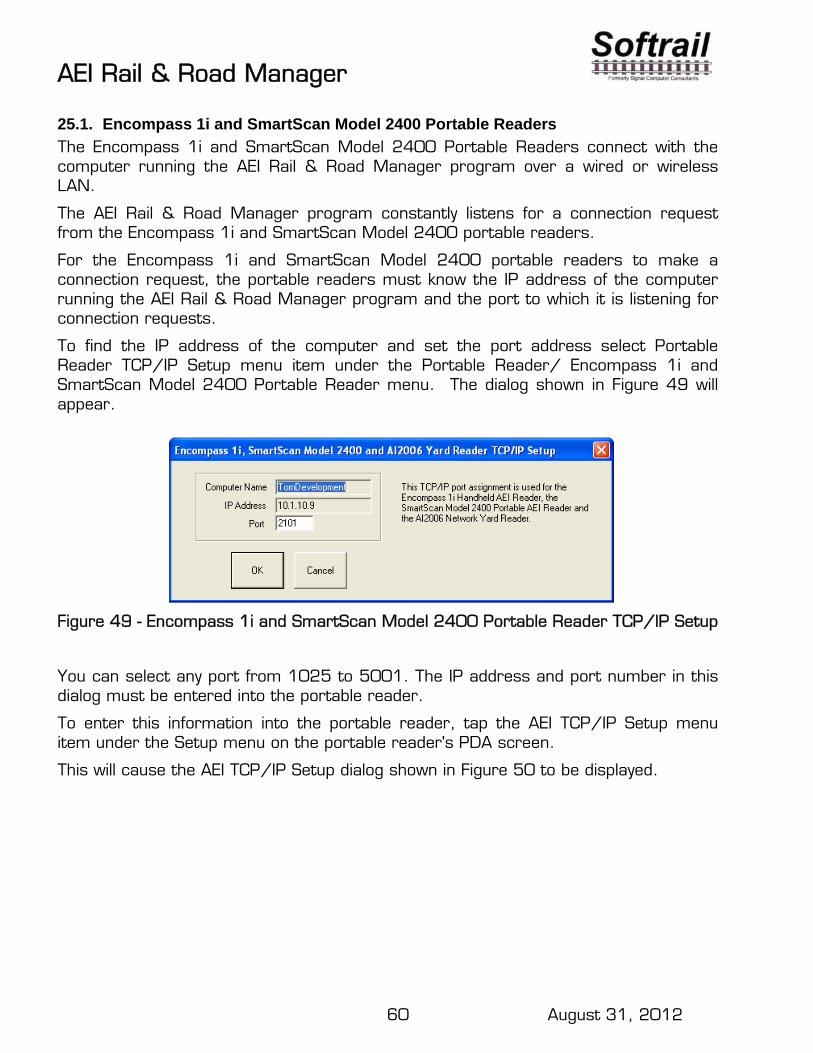
AEI Rail & Road Manager
60 August 31, 2012
25.1. Encompass 1i and SmartScan Model 2400 Portable Readers
The Encompass 1i and SmartScan Model 2400 Portable Readers connect with the computer running the AEI Rail & Road Manager program over a wired or wireless LAN.
The AEI Rail & Road Manager program constantly listens for a connection request from the Encompass 1i and SmartScan Model 2400 portable readers.
For the Encompass 1i and SmartScan Model 2400 portable readers to make a connection request, the portable readers must know the IP address of the computer running the AEI Rail & Road Manager program and the port to which it is listening for connection requests.
To find the IP address of the computer and set the port address select Portable Reader TCP/IP Setup menu item under the Portable Reader/ Encompass 1i and SmartScan Model 2400 Portable Reader menu. The dialog shown in Figure 49 will appear.
Figure 49 - Encompass 1i and SmartScan Model 2400 Portable Reader TCP/IP Setup
You can select any port from 1025 to 5001. The IP address and port number in this dialog must be entered into the portable reader.
To enter this information into the portable reader, tap the AEI TCP/IP Setup menu item under the Setup menu on the portable reader's PDA screen.
This will cause the AEI TCP/IP Setup dialog shown in Figure 50 to be displayed.

AEI Rail & Road Manager
61 August 31, 2012
Figure 50 - AEI RR TCP/IP Setup Dialog
Enter the IP address and port information that was displayed in the AEI Rail & Road Manager's Model 2400 Portable Reader Setup dialog (see Figure 49).
This display also shows the portable reader's PDA Name and the current IP address of the PDA.
Whenever the user finishes taking inventory on a particular track, the portable reader will ask the user if he wishes to send the track inventory to the AEI Rail & Road Manager. If he does, the inventory will be sent as soon as the portable reader makes a connection with the computer running the AEI Rail & Road Manager program and the rail vehicles will appear on the appropriate track.
25.2. SmartScan Model 2200 Portable Reader
25.2.1. Establishing the SmartScan Portable Reader to Computer Interface
The SmartScan Model 2200 Portable Reader comes with a communications cable terminated on one end by a serial connector (either 9 pin or 25 pin male connector). This cable is connected to a serial port on the back of the personal computer. The other end of the cable has an RJ-45 connector that fits the combined charging/communications port on the portable reader.
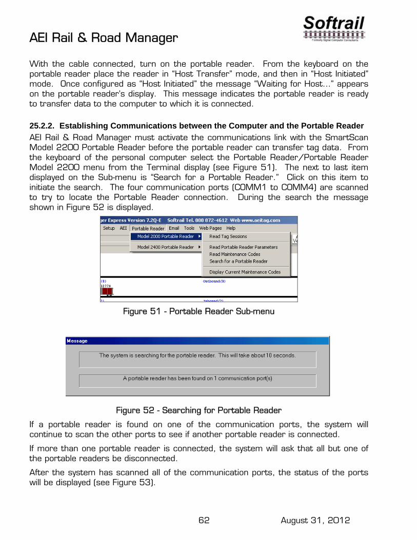
AEI Rail & Road Manager
62 August 31, 2012
With the cable connected, turn on the portable reader. From the keyboard on the portable reader place the reader in “Host Transfer” mode, and then in “Host Initiated” mode. Once configured as “Host Initiated” the message “Waiting for Host…” appears on the portable reader’s display. This message indicates the portable reader is ready to transfer data to the computer to which it is connected.
25.2.2. Establishing Communications between the Computer and the Portable Reader
AEI Rail & Road Manager must activate the communications link with the SmartScan Model 2200 Portable Reader before the portable reader can transfer tag data. From the keyboard of the personal computer select the Portable Reader/Portable Reader Model 2200 menu from the Terminal display (see Figure 51). The next to last item displayed on the Sub-menu is “Search for a Portable Reader.” Click on this item to initiate the search. The four communication ports (COMM1 to COMM4) are scanned to try to locate the Portable Reader connection. During the search the message shown in Figure 52 is displayed.
Figure 51 - Portable Reader Sub-menu
Figure 52 - Searching for Portable Reader
If a portable reader is found on one of the communication ports, the system will continue to scan the other ports to see if another portable reader is connected.
If more than one portable reader is connected, the system will ask that all but one of the portable readers be disconnected.
After the system has scanned all of the communication ports, the status of the ports will be displayed (see Figure 53).

AEI Rail & Road Manager
63 August 31, 2012
Figure 53 - Portable Reader Connection Status
Figure 53 shows the status of each port and indicates which port is connected to the portable reader.
If the user clicks the Refresh button on this dialog, the system will start a new search for a portable reader.
Clicking on the Portable Reader Parameters button will cause the display shown in Figure 54 to appear, which shows the portable reader’s internal parameters.
Figure 54 - Portable Reader Parameters
Figure 54 can also be displayed by selecting the Read Portable Reader Parameters sub-menu item under the Portable Reader/Model 2200 Portable Reader menu (see Figure 51).

AEI Rail & Road Manager
64 August 31, 2012
25.2.3. Problems Connecting with the Portable Reader
If a portable reader is not found, check the following:
Make sure there is a good cable connection between the portable reader and the computer
Make sure the cable is plugged into one of the communication ports (9 or 25 pin connector on the back of the computer)
Make sure the portable reader is in the Host Transfer/Host Initiated mode (the portable reader is displaying the “Waiting for Host…” message).
If the portable reader is still not found, try another 9 or 25 pin connector on the back of the computer.
If the portable reader is still not found, check the display in Figure 53 to see if there are any active ports. If no ports are active check the computer manual on how to activate a communication port.
If the portable reader continues to not be found, contact us by telephone at 724 942-1473. When you call please be at your computer with Figure 53 displayed.
25.2.4. Transferring Tag Data from the Portable Reader
Transferring tag data from the portable reader is a two-step process. The first step is to transfer headers for all of the tag sessions stored in the portable reader.
A tag session is a group of tag reads stored together. For example, the tags on all of the vehicles on one track may be read as one session, and the vehicles on the next track may be read and stored together as a second session. The portable reader operator determines when one session ends and another begins. The portable reader can store up to 99 sessions.
To display a list of all the stored tag sessions, select the Read Tag Sessions item under the Portable Reader menu (see Figure 51). A message will then appear showing the progress in transferring the session headers from the portable reader to the computer. Once all of the session headers are transferred the dialog shown in Figure 55 will be displayed.

AEI Rail & Road Manager
65 August 31, 2012
Figure 55 - List of Tag Sessions
Figure 55 shows the display which lists the tag sessions stored in the reader. This list shows the tag session number, the date and time the tags in the session were stored in the portable reader, the number of tags stored for the session, the vehicle ID of the first tag stored in the session, and the ID of the portable reader in which the session data is stored.
Highlight a session by placing the mouse cursor on the session and clicking the left mouse button. Multiple sessions can be selected for transferring at the same time.
To transfer the actual tag data in the selected session(s), click the Read Selected Sessions’ Tags button. The system shows the progress in transferring the data by displaying the message in Figure 56.
Figure 56 - Transferring Sessions Data Progress Message
Once all of the data for a given session is transferred, the dialog shown in Figure 57 will be displayed.

AEI Rail & Road Manager
66 August 31, 2012
Figure 57 - Portable Reader Data Track Selection
This dialog allows the user to select the track on which the session’s tags will be added or compared with existing vehicles. The selected track can be an existing track already displayed or a new track. Any alphanumeric name up to 20 characters long can be assigned to a new track.
A new track created by the user via the dialog above will continue to be displayed as long as there are rail vehicles on it. When there no longer are any vehicles on a track, it will be erased the next time the AEI Rail & Road Manager program is started.
In Figure 57 we have designated the cars in the session to replace the cars on a track called “portable”. The result of this action can be seen in Figure 58.
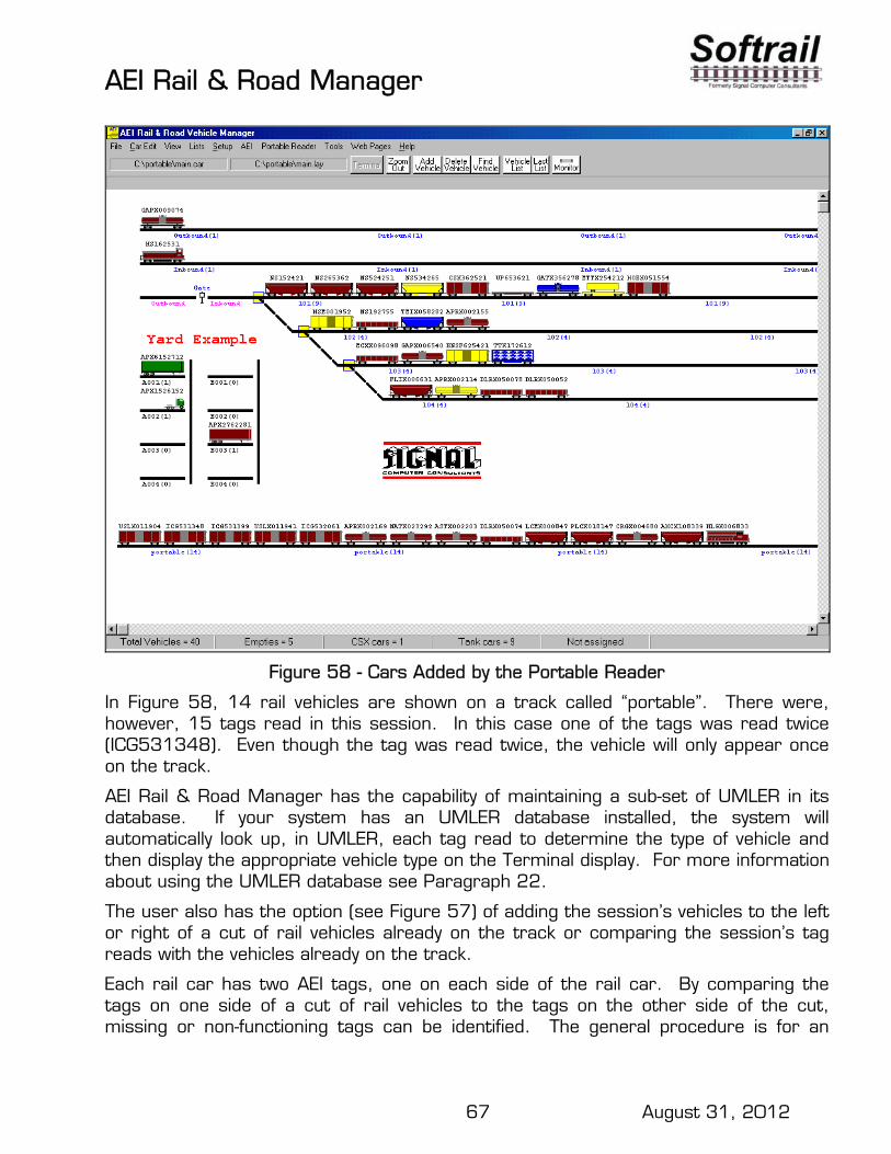
AEI Rail & Road Manager
67 August 31, 2012
Figure 58 - Cars Added by the Portable Reader
In Figure 58, 14 rail vehicles are shown on a track called “portable”. There were, however, 15 tags read in this session. In this case one of the tags was read twice (ICG531348). Even though the tag was read twice, the vehicle will only appear once on the track.
AEI Rail & Road Manager has the capability of maintaining a sub-set of UMLER in its database. If your system has an UMLER database installed, the system will automatically look up, in UMLER, each tag read to determine the type of vehicle and then display the appropriate vehicle type on the Terminal display. For more information about using the UMLER database see Paragraph 22.
The user also has the option (see Figure 57) of adding the session’s vehicles to the left or right of a cut of rail vehicles already on the track or comparing the session’s tag reads with the vehicles already on the track.
Each rail car has two AEI tags, one on each side of the rail car. By comparing the tags on one side of a cut of rail vehicles to the tags on the other side of the cut, missing or non-functioning tags can be identified. The general procedure is for an
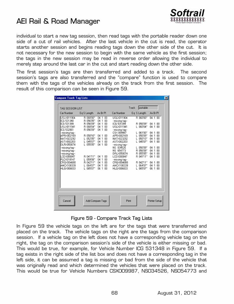
AEI Rail & Road Manager
68 August 31, 2012
individual to start a new tag session, then read tags with the portable reader down one side of a cut of rail vehicles. After the last vehicle in the cut is read, the operator starts another session and begins reading tags down the other side of the cut. It is not necessary for the new session to begin with the same vehicle as the first session; the tags in the new session may be read in reverse order allowing the individual to merely step around the last car in the cut and start reading down the other side.
The first session’s tags are then transferred and added to a track. The second session’s tags are also transferred and the “compare” function is used to compare them with the tags of the vehicles already on the track from the first session. The result of this comparison can be seen in Figure 59.
Figure 59 - Compare Track Tag Lists
In Figure 59 the vehicle tags on the left are for the tags that were transferred and placed on the track. The vehicle tags on the right are the tags from the comparison session. If a vehicle tag on the left does not have a corresponding vehicle tag on the right, the tag on the comparison session’s side of the vehicle is either missing or bad. This would be true, for example, for Vehicle Number ICG 531348 in Figure 59. If a tag exists in the right side of the list box and does not have a corresponding tag in the left side, it can be assumed a tag is missing or bad from the side of the vehicle that was originally read and which determined the vehicles that were placed on the track. This would be true for Vehicle Numbers CSX009987, NS034526, NS054773 and

AEI Rail & Road Manager
69 August 31, 2012
DRLX050074. To add these vehicles (a missing tag message is in the corresponding position on the left side of the list box) to the track, the user would click the Add Compare Tags button. This adds the vehicle tags on the right side of the list box that do not have a corresponding vehicle tag on the left side of the list box to the track and places them in the appropriate position. See Figure 60 for the results of adding the comparison session’s tags.
Figure 60 - Adding Comparison Vehicle Tags
The four vehicles that were in the comparison session list of tags and not already on the track have now been added to the track called “portable”.
25.2.5. Portable Reader Maintenance Code
When a tag is read by a portable reader, a two-digit maintenance code can be appended to the tag data by the portable reader’s operator. This maintenance code is also transferred to the AEI Rail & Road Manger program with the tag data.
The portable reader maintains a list of maintenance code descriptions that can be transferred to this system. To transfer the maintenance code descriptions, select the

AEI Rail & Road Manager
70 August 31, 2012
Read Maintenance Code item under the Portable Reader/Scan Model 2200 menu. This will cause the dialog in Figure 61 to be displayed.
Figure 61 - Maintenance Codes
The list box in Figure 61 shows the two-digit code number, the description, and by whom the maintenance code was defined. Users can add their own maintenance code descriptions to numbers that are not already used by the portable reader.
To change an existing description or add a new one, select the code in the list by placing the mouse cursor on the code number and click the left mouse button, then type the new or altered description in the Description field and click the Change button. Figure 62 shows the “Brake Hose” description added as Maintenance Code 35.

AEI Rail & Road Manager
71 August 31, 2012
Figure 62 - Added Maintenance Code
26. AI2006 WAYSIDE AEI TAG READERS The system is designed to work in conjunction with AI2006 Network Yard AEI readers (see Figure 63). AEI readers will allow the system to automatically track vehicles and update their locations on the user specified tracks in the Terminal display. There can be up to one hundred active AEI reader sites on the Terminal display.
Figure 63 - AI2006 Network Yard AEI Reader
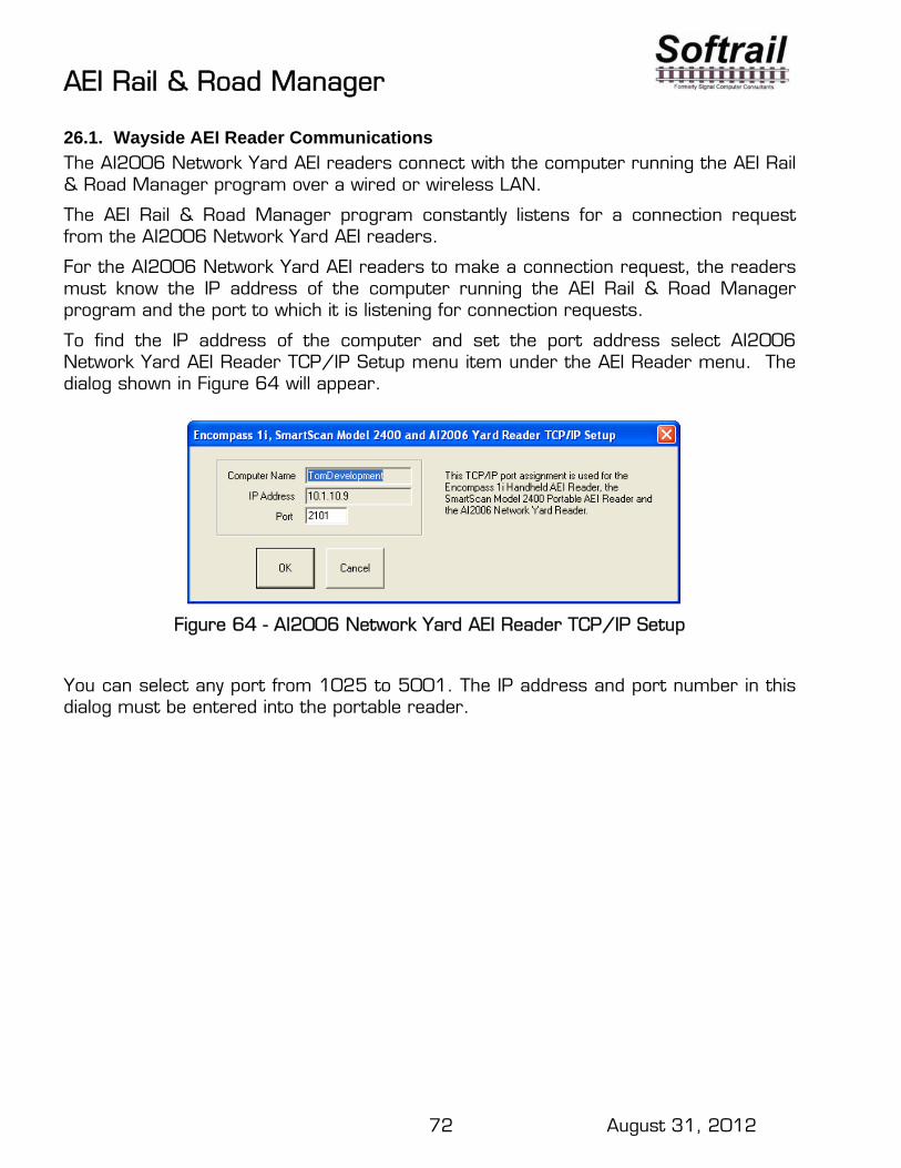
AEI Rail & Road Manager
72 August 31, 2012
26.1. Wayside AEI Reader Communications
The AI2006 Network Yard AEI readers connect with the computer running the AEI Rail & Road Manager program over a wired or wireless LAN.
The AEI Rail & Road Manager program constantly listens for a connection request from the AI2006 Network Yard AEI readers.
For the AI2006 Network Yard AEI readers to make a connection request, the readers must know the IP address of the computer running the AEI Rail & Road Manager program and the port to which it is listening for connection requests.
To find the IP address of the computer and set the port address select AI2006 Network Yard AEI Reader TCP/IP Setup menu item under the AEI Reader menu. The dialog shown in Figure 64 will appear.
Figure 64 - AI2006 Network Yard AEI Reader TCP/IP Setup
You can select any port from 1025 to 5001. The IP address and port number in this dialog must be entered into the portable reader.

AEI Rail & Road Manager
73 August 31, 2012
To enter this information into the AI2006 Network Yard AEI Reader, tap the TCP/IP Setup menu item under the Setup menu on the portable reader's PDA screen.
This will cause the AEI TCP/IP Setup dialog shown in Figure 65 to be displayed.
Figure 65 - AI2006 TCP/IP Setup Dialog
Enter the IP address and port information that was displayed in the AEI Rail & Road Manager's Model 2400 Portable Reader Setup dialog (see Figure 65).
This display also shows the AI2006 reader's PDA Name and the current IP address of the PDA.
Whenever the AI2006 reader finishes processing a train it will automatically make a connection with the computer running the AEI Rail & Road Manager program and transfer the data on the rail vehicles.

AEI Rail & Road Manager
74 August 31, 2012
26.2. Identifying the AI2006 Reader
Each AI2006 reader that communicates with the AEI Rail & Road Manager program must have a unique name. This name is entered into the AI2006 reader’s PDA by going to the Setup/Reader Site menu item. The dialog in Figure 66 will appear.
Figure 66 - AI2006 Reader Site Setup Dialog
A reader with the same site name must also appear on the AEI Rail & Road Manager Software Terminal layout. Go to Paragraph 23.6 for information about adding a reader to the Terminal layout.

AEI Rail & Road Manager
75 August 31, 2012
26.2.1. Turning on Wayside AEI Reader Communications
In a single user system, the computer that communicates with the wayside AEI readers (acts as the wayside AEI reader server) is the same computer that runs AEI Rail & Road Manager. In multi-user systems only one of the computers that run AEI Rail & Road Manager can be the wayside AEI reader server.
To select the computer that will act as the wayside AEI reader server select the Setup/Wayside AEI Reader Server Selection menu item. The dialog shown in Figure 67 will appear.
Figure 67 - Wayside AEI Reader Server Selection
Softrail will provide the system administrator with a code to turn this function on. To turn this function off select the Setup/Wayside AEI Reader Server Selection menu item again.
26.2.2. Wayside AEI Reader Status
The status of each wayside AEI reader site is displayed on the screen (see Figure 68).
Figure 68 - Wayside AEI Reader Status

AEI Rail & Road Manager
76 August 31, 2012
The following table describes the meaning of the various reader icons:
Color of Reader
Color of X over Reader
Reader Status
Black No X The status is Ok.
Red No X The status is Ok. The reader presence monitor is on (showing occupied)
Black Red X Server is having problems communicating with the reader.
Black Black X Communications with the reader has been manually disabled.
26.2.3. Enabling/Disabling Wayside Reader Communications
To enable or disable wayside reader communications, place the mouse pointer on the reader icon and click the right mouse button. The pop-up menu shown in Figure 69 will appear.
Figure 69 - Enabling/Disabling Wayside AEI Reader
This pop-up menu also allows the user to quickly display the communications monitor (see Paragraph 26.2.4), communications log (see Paragraph 26.3) and reader properties dialog (see Paragraph 23.6) for the selected reader.
26.2.4. Monitoring Communications
To monitor communications select the Communications Monitor menu item under the AEI menu, or place the mouse pointer on the reader, click the right mouse button and

AEI Rail & Road Manager
77 August 31, 2012
select the Communications Monitor item. This will cause the screen displayed in Figure 70 to appear.
This display shows the last 500 communication records transmitted or received by the port designated in the Port field. The user may scroll to see previous records. The last record transmitted or received is displayed at the top of the box.
Figure 70 - Communications Monitor
Communication records that are transmitted by the computer have a “T--“ designation in front of the record and “R—“ for a received record. In Figure 70 the computer connects the AI2006 Reader named “Gate”, receives the rail vehicle data, acknowledges the message and then closes the connection.
Every 60 seconds each AI2006 reader will make a connection and send a message to the AEI Rail & Road Manager software. If the AEI Rail & Road Manager does not receive message from the AI2006 reader with 2 minutes, it will place a red X over the reader icon on the terminal layout indicating it have a problem communicating with the reader.
26.3. Communication Logs
As a diagnostic tool the system keeps a log of all communications with the AEI Rail & Road Manager program. The communications log is in a file called “server comm. log.txt”. This file is a text file, which can be viewed, accessed or modified by most standard word processing programs.
The system also gives the user the ability to view these files by selecting the Communications Log menu item under the AEI Reader menu.

AEI Rail & Road Manager
78 August 31, 2012
The communications log shows the time of each communication record on the left side of the screen. The newest record is at the bottom of the screen. The user can scroll up the screen to see older records.
Records sent by the computer are preceded with a “T--“ and an “R--“ is a received record.
Because the communication logs can become very large the system automatically deletes records based on file size or the age of the record. The user specifies these parameters by using the Automatic Deletion of Communication Records function in Paragraph 19.4
Figure 71 - Communications Log
27. Email Setup The AEI Rail & Road Manager program can send AEI reader maintenance data via email. It can also send emails on various reader problems to a list of user-entered email addresses. The AEI Rail & Road Manager program does not receive emails.
To send AEI reader maintenance data via email, the AEI Rail & Road Manager program must know the following:
The name of the outgoing mail server (STMP)
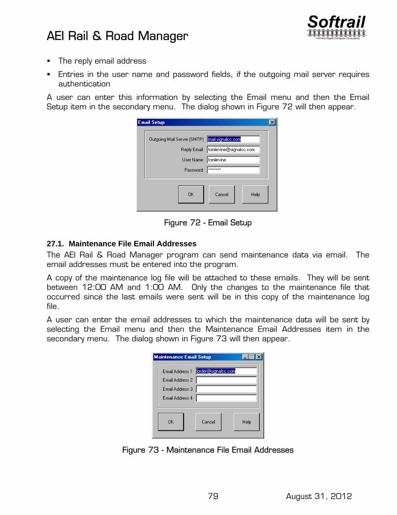
AEI Rail & Road Manager
79 August 31, 2012
The reply email address
Entries in the user name and password fields, if the outgoing mail server requires authentication
A user can enter this information by selecting the Email menu and then the Email Setup item in the secondary menu. The dialog shown in Figure 72 will then appear.
Figure 72 - Email Setup
27.1. Maintenance File Email Addresses
The AEI Rail & Road Manager program can send maintenance data via email. The email addresses must be entered into the program.
A copy of the maintenance log file will be attached to these emails. They will be sent between 12:00 AM and 1:00 AM. Only the changes to the maintenance file that occurred since the last emails were sent will be in this copy of the maintenance log file.
A user can enter the email addresses to which the maintenance data will be sent by selecting the Email menu and then the Maintenance Email Addresses item in the secondary menu. The dialog shown in Figure 73 will then appear.
Figure 73 - Maintenance File Email Addresses
AEI Rail & Road Manager
80 August 31, 2012
27.2. Reader Problem Email Setup
The AEI Rail & Road Manager program can also send emails about individual reader problems to a list of email addresses. There are four types of messages the AEI Rail & Road Manager program will send. These are: the server has not been able to communicate with an AEI reader for 10 minutes the server has not been able to communicate with an AEI reader for 1 hour an AEI reader's presence detector is on and there have been no wheel detectors
hits for over 1 hour the status of the AEI reader is OK after there was a previously reported problem
Each of these messages can include the name of the reader and the time the message was generated.
The user can specify: the text in the body of the email for each type of email the text in the subject for each type of email the list of up to twenty email addresses that will receive the reader problem emails
A user can enter this information by selecting the Email menu and then the Reader Problem Email Setup item in the secondary menu. The display shown in Figure 74 will then appear.

AEI Rail & Road Manager
81 August 31, 2012
Figure 74 - Reader Problem Email Setup
The user can specify the text that will appear in the email. The text must be provided in a separate text file (.txt). The name and location of this file is specified next to the type of message associated with the text. To easily locate the text file, the Browse button next to the field can be used. To view or edit the file's contents click the Open button. This will cause a Notepad Window to open and display the contents of the file (see Figure 75).
Please note that this file must be accessible from the computer running as the AEI server.
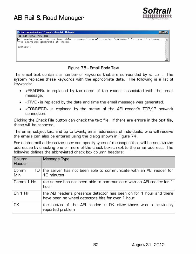
AEI Rail & Road Manager
82 August 31, 2012
Figure 75 - Email Body Text
The email text contains a number of keywords that are surrounded by <…..> . The system replaces these keywords with the appropriate data. The following is a list of keywords:
<READER> is replaced by the name of the reader associated with the email message.
<TIME> is replaced by the date and time the email message was generated.
<CONNECT> is replaced by the status of the AEI reader's TCP/IP network connection.
Clicking the Check File button can check the text file. If there are errors in the text file, these will be reported.
The email subject text and up to twenty email addresses of individuals, who will receive the emails can also be entered using the dialog shown in Figure 74.
For each email address the user can specify types of messages that will be sent to the addressee by checking one or more of the check boxes next to the email address. The following defines the abbreviated check box column headers:
Column Header
Message Type
Comm 10 Min
the server has not been able to communicate with an AEI reader for 10 minutes
Comm 1 Hr the server has not been able to communicate with an AEI reader for 1 hour
On 1 Hr the AEI reader's presence detector has been on for 1 hour and there have been no wheel detectors hits for over 1 hour
OK the status of the AEI reader is OK after there was a previously reported problem

AEI Rail & Road Manager
83 August 31, 2012
27.3. Sending a Test Email
A test email can be sent by selecting the Email/Send Test Email menu item. The test email will be sent to all email addresses in Figure 74 that have the "Ok" check box checked.
28. EMAIL NOTIFICATIONS The system is designed to send email notifications when vehicles pass AEI reader sites. These notifications contain a list, in an attached file, of vehicles that have passed an AEI reader. The user can specify the following email criteria:
Who should receive the emails What vehicles should be reported (based on consignee or consignor name) What AEI sites will cause the emails to be generated What direction the vehicles must pass the specified AEI reader site for the
email to be generated The subject of the email. Any text (in addition to the list of vehicles ) of the email. Who should be sent copies of all emails
The following is an example of the text in an email generated by the system:
Evergreen America.
The attached file contains a list of cars have arrived at the Tacoma Rail Yard on 10/23/2002 10:11.
The data are based on the AEI reader site at Bullfrog Junction.
Please Note: While the AEI reader data are accurate, not all AEI tags mounted on vehicles
perform accurately at all times. From time to time a vehicle may not be identified correctly or
identified at all.
The following describes the email system in detail.
28.1. Displaying the Email Records
The Email List display is a list of email records. Each email record contains a set of criteria for generating email notifications. This list can be displayed by choosing the Email Notification List menu item under the Email menu. The will cause the Email List dialog to appear as shown in Figure 76.
A list of email records is displayed in the list box on the left hand side of the display. Each record must have a unique name, which can be up to 10 characters.

AEI Rail & Road Manager
84 August 31, 2012
Figure 76 - Email Record List Display
28.2. Adding an Email Record
To add a new email record, enter a unique name that describes the email record in the Email Record Name field.
The Customer Name field is used to determine which vehicles and containers will be reported in the email. The customer name is checked against the vehicles' and containers' EDI 418 consignee and/or consignor names. If there is a match between the customer name and the consignee and/or consignor name, the vehicle or container will be reported.
The Report When Consignee and Report When Consignor check boxes determine if the system will attempt to check against the EDI 418 consignee name, consignor name or both.
The comparison is made only on the number of characters in the Customer Name field. If the Customer Name field contains "EVER" then an EDI 418 consignee name of "EVERGAMERIC" would be considered a match since the first four characters of the Customer Name field agree with the first four characters in the EDI 418 consignee name. The comparison is not case sensitive.
If the Customer Name field is blank and the Report When Consignee check box is checked, then all vehicles and containers will be reported.
The Email Address field contains the address where the email will be sent. Multiple email addresses can be entered, but a semicolon must separate them.
The Email Subject field contains the text for the email's subject.

AEI Rail & Road Manager
85 August 31, 2012
The user can specify the text that will appear in the email. The text must be provided in a separate text file (.txt). The name and location of this file is specified in the Email Text File field. To easily locate the text file, the Browse for Text File button below the field can be used. To view or edit the file's contents click the Open button. This will cause a Notepad Window to open and display the contents of the file (see Figure 77).
Please note that the path to this file must be from the computer that is running as the wayside reader server.
Figure 77 - Email Text File
The email text contains a number of keywords that are surrounded by <…..> . The system replaces these keywords with the appropriate data. The following is a list of keywords:
<TIME> is replaced by the date and time when the reader reported the passage of the vehicles/containers.
<READER> is replaced by the name of the reader that reported the passage of the vehicles/containers.
<DIRECTION> is replaced by the direction in which the vehicles passed the reader.
<LIST> is replaced by a list of rail cars that passed the reader and met the consignee/consignor match test. This list is the same list that is in the email's attached file.
Clicking the Check Text File button can check the text file. If there are errors in the text file, these will be reported.
Once the above information is entered correctly, click the Add New button to save the email record.

AEI Rail & Road Manager
86 August 31, 2012
To complete the task of entering an email record, the readers that trigger the generation of the email must be assigned. To assign the readers click the Assign Reporting Readers button. This will cause the Email Reader Reporting List dialog to appear (see Figure 78).
This list shows the AEI readers that will cause this email to be generated and the direction a train must pass each reader.
To delete readers from this list, select the readers to be deleted and click the Delete Selected Reader from List button.
To change the reporting direction of a reader, select a reader. This will cause the Reporting Direction check boxes to reflect the selected reader's reporting directions. To change the reporting direction, check or uncheck the appropriate check box and then click the Change Reader Reporting Direction button.
Figure 78 - Email Reader Reporting List Display
To add a reporting reader to the list, click the Add Reporting Reader button. This will cause the Add Reporting Readers dialog in Figure 79 to appear. Only the readers that can be added to the reporting list will appear. Select the reader(s) to be added to the reporting list and then click the Add Selected Readers button. Multiple readers can be selected at once. When you click the Close button, the Email Reader Reporting List display again becomes active. Make sure you check and update the reporting directions for the added readers.

AEI Rail & Road Manager
87 August 31, 2012
Figure 79 - Add Reporting Readers
The following is an example of the list of vehicles in the file attached to the email:
RR BNSF237219,101 RR MP 526412,101 RR UP 981712,101 RR CSX 172812,101 RR NS 524162,101
A line starting with RR indicates that the line represents a vehicle. The following is a description of the fields in this line:
RR Railcar designator Railcar ID (initial and number) Current location of vehicle (track or train)
28.3. Changing an Email Record
To change an email record, select the email record name in the list box in the Email List dialog. This will cause the other fields in the display to contain the information from the record. After changing the information, click the Change Selected button to save the changes.

AEI Rail & Road Manager
88 August 31, 2012
28.4. Delete an Email Record
To delete an email record, select the email record name in the list box in the Email List dialog and then click the Delete Selected button.
28.5. Sending a Test Email
To send a test email, select an email record name in the list box in the Email List dialog list and click the Send Test Email button. The test email will be sent to the test email address as entered in the Email Addresses dialog (see Paragraph 28.6).
Please note that test emails can only be sent from the computer designated as the wayside AEI reader server.
28.6. Email Return, Copy and Test Email Addresses Setup
Emails sent must have a return email address. To enter the return email address, select the Email Notification Addresses menu item under the Setup menu. This will cause the Email Notification Addresses dialog shown in Figure 80 to appear.
Through this display the user also enters copy email addresses so that sent emails can be monitored.
The test e-mail address is also entered via this display. This is the address to which test emails will be sent when the Send Test Email button is clicked in the Email Record List display.
Figure 80 - Email Notification Addresses

AEI Rail & Road Manager
89 August 31, 2012
29. EDI 418 FILE MESSAGE FOLDERS The system is designed to process EDI 418 messages contained in files. The system needs to know in what folders the files are located. To enter this information, select the EDI 418 Folder menu item under the Setup menu. This will cause the EDI 418 Folder Setup display shown in Figure 81 to appear.
Up to ten folders can be entered. The Browse buttons can be used to help locate the folders and their paths.
All EDI 418 files are text files; however, they may not have .txt as their file extensions.
A file name format can be specified for each folder in the EDI File Name field. The system will only process files whose names match the file name format in the EDI File Name field. Asterisks in this field specify wildcard values. For an example, *.* specifies that any file in the folder will be processed, and BNSFEDI.* specifies that all files beginning with BNSFEDI. will be processed.
Figure 81 - EDI 418 Folder Setup Display
30. FTP Setup The system can obtain EDI 418 messages created by a serving railroad from a railroad computer using File Transfer Protocol. To perform this function the AEI Rail & Road Manager program must know the following:
The name or IP address of the railroad's FTP server

AEI Rail & Road Manager
90 August 31, 2012
The port to which the FTP Server program is listening (usually 21)
The path to the folder that contains the EDI 418 files
The user name and password
A user can enter this information by selecting the FTP menu item under the Setup menu. The dialog in Figure 82 will then appear.
Figure 82 - FTP Setup
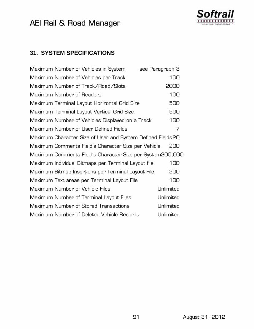
AEI Rail & Road Manager
91 August 31, 2012
31. SYSTEM SPECIFICATIONS
Maximum Number of Vehicles in System see Paragraph 3
Maximum Number of Vehicles per Track 100
Maximum Number of Track/Road/Slots 2000
Maximum Number of Readers 100
Maximum Terminal Layout Horizontal Grid Size 500
Maximum Terminal Layout Vertical Grid Size 500
Maximum Number of Vehicles Displayed on a Track 100
Maximum Number of User Defined Fields 7
Maximum Character Size of User and System Defined Fields 20
Maximum Comments Field’s Character Size per Vehicle 200
Maximum Comments Field’s Character Size per System200,000
Maximum Individual Bitmaps per Terminal Layout file 100
Maximum Bitmap Insertions per Terminal Layout File 200
Maximum Text areas per Terminal Layout File 100
Maximum Number of Vehicle Files Unlimited
Maximum Number of Terminal Layout Files Unlimited
Maximum Number of Stored Transactions Unlimited
Maximum Number of Deleted Vehicle Records Unlimited


AEI Rail & Road Manager
1 August 31, 2012
Index add a vehicle. See vehicle, add AEI reader, 30, 47, 71, 91
communication log, 77 communication monitoring, 76
AI2006 reader, 71 Archive List display, 31 Archive Search dialog, 31 Automatic Vehicle Deletion display, 19 background
bitmap, 51 rules, 57 text area, 56
backup file. See file,backup bitmap
add, 50 changing, 53 delete, 52 duplicate, 53 maintenance, 53 maximum, 91 modify, 52 resize, 53
Bitmap Maintenance Function, 53 bitmaps, 50 color
text, 55 communication log. See AEI
reader:communication log communication records
automatic deletion, 39 communications. See AEI reader. See AEI
reader default
restore fields, 34 vehicle color, 17
delete a vehicle. See vehicle, delete draw terminal layout, 43
AEI reader, 47 clearing (removing) track/road symbols, 44 clearing a group of grid squares, 49 draw track/road symbols, 44 duplicating track/roadsymbols, 45 inserting columns and rows, 44 moving a selected group of squares, 49 save layout file, 58 selecting a group of grid squares, 48 track/road names, 45
EDI418, 89 vehicle, 11
email notifications, 83 email setup, 78 export data, 34, 36 field
Comments, 30, 31, 32, 33, 91 Consist, 33, 34, 40 Status, 33, 34, 40 Time In, 17, 47 Time Out, 17 Vehicle Number, 18, 31, 33 Vehicle Type, 33, 34
file archive, 33, 37 backup, 37 backup (automatic), 37 communication, 39 maintenance, 37 new vehicle, 4 open layout, 4 open terminal, 43 open vehicle, 4 terminal layout, 4, 91 transaction, 31, 37, 38 vehicle data, 4, 37, 91
File Maintenance dialog, 37 find a vehicle. See vehicle, find foreground
bitmap, 51 rules, 57 text area, 56
FTP transfer, 89 General Vehicle Information display, 8 graphics. See bitmaps installation
program, 1 justification
track, 7 log
communication, 39 maintenance, 39
maintenance codes portable reader, 69
maintenance file email addresses, 79 maintenance log, 39 Memorized List Maintenance dialog, 40 Memorized Search and Report Layout display,
20 movement history
vehicle, 13

AEI Rail & Road Manager
2 August 31, 2012
moving a vehicle. See vehicle, move network
File Maintenance Manager selection, 39 file sharing, 58
new vehicle file, 4. See file:new vehicle open layout file. See file:open layout open vehicle file. See file:open vehicle options, 2 password, 27, 28, 30, 58 Password entry, 28 Password Maintenance display, 27 portable reader
maintenance codes, 69 model 2200, 62 model 2400, 60 parameters, 63 problems reading, 64 reading tag data, 64 tag comparisons, 67 tag sessions, 65 TCP/IP setup, 60
print archive list, 33 track shortcut, 27 transaction list, 31 vehicle list, 25, 36
problems reading portable reader. See portable reader, problems reading
reader. See AEI reader Restore Fields dialog, 34 reverse track inventory, 36 reversing track inventory, 36 save layout file, 58 selecting a vehicle. See vehicle,select serial number, 3 shortcut
export track, 36 reversing track, 36 track printing, 27 vehicle track list, 27
SmartScan Model 2200 Portable Reader, 62 SmartScan Model 2400 Portable Reader, 60 starting the program, 1 Technical Support, 3 Terminal Configure Layout
insert and delete columns and rows, 49 Terminal display, 4
zoom, 6 text area, 54
add, 54 background and foreground, 56 changing, 57
color, 55 deleting, 56 duplicating, 57 font, font size, font style, 55 maximum, 91 modifying, 56 moving, 56
track, 91 left/right justification, 7
Track/road Information dialog, 45 Transaction List display, 29, 31 transaction records, 91
automatic deletion, 38 Transaction Search dialog, 29 UMLER, 12
Data Specification Manual, 43 Database, 41 Loading Database, 42 Searching for vehicles, 42
User Defined Fields, 91 User Defined Fields display, 10, 14, 15, 16 User Defined Status Line display, 17 User Defined Vehicle Colors display, 16 vehicle
add, 18, 33 add from portable reader, 64 delete, 18, 36 delete (automatic), 19 delete all cars on a track, 36 EDI418, 11 find, 19 general data, 8 left/right justification, 7 move, 4 movement history, 13 moving multiple vehicle, 5 multiple platform, 10 orientation, 2, 10 select, 6 type, 9 UMLER, 12
Vehicle Colors display, 16 Vehicle Information display, 8, 15, 24 Vehicle List display, 20, 23, 36 Vehicle List Search dialog, 35 Vehicle Number. See field, vehicle number Vehicle Search Criteria display, 21 version, 3 Web Page
Association of American Railroads, 43 Softrail, 3
zoom, 6

AEI Rail & Road Manager
1 August 31, 2012