ae 1005-automotive engines unit 1 · v engine crankshaft, connecting rod and piston assembly ....
TRANSCRIPT
AE 1005-AUTOMOTIVE ENGINES
Unit 1
UNIT I - ENGINE CONSTRUCTION AND OPERATION
(9 hours)
Four stroke SI and CI engines - Working principle function,
materials, constructional details of engine components-materials, constructional details of engine components-
Valve timing diagram - Firing order and its significance -
relative merits and demerits of SI and CI engines Two stroke
engine construction and operation. Comparison of four-
stroke and two-stroke engine operation.
Engine Classifications 1. Types of ignition
(a) Spark Ignition (SI)
• An SI engine starts the combustion process in each cycle by use of a spark plug.
(b) Compression Ignition (CI)
• The combustion process in a CI engine starts when the air-fuel mixture self-ignites due to high temperature in the
combustion chamber caused by high compression.
2. Engine cycle 2. Engine cycle
(a) Four-stroke cycle
• A four-stroke cycle has four piston movements over two engine revolutions for each cycle.
(b) Two-stroke cycle:
• A two-stroke cycle has two piston movements over one revolution for each cycle.
3. Valve location
(a) Valves in head (Overhead valve), also called I Head engine.
(b) Valves in block (flat head), also called L Head engine.
• Some historic engines with valves in block had the intake valve on one side of the cylinder and the exhaust valve on the other side. These were called T Head engines.
(c) One valve in head (usually intake) and one in block, also called F Head Engine; this is much less common.
4. Basic Design
a. Reciprocating
• Engine has one or more cylinders in which pistons reciprocate back and forth.
b. Rotary
• Engine is made of a block (stator) built around a large non-concentric rotor and crankshaft. The combustion chambers are built into the non-rotating block
5. Position and number of cylinders of reciprocating engines
a. Single Cylinder
• Engine has one cylinder and piston connected to the crankshaft.
b. In-Line
• Cylinders are positioned in a straight line, one behind the other along the length of the crankshaft.• Cylinders are positioned in a straight line, one behind the other along the length of the crankshaft.
c. V Engine
• Two banks of cylinders at an angle with each other along a single crankshaft, allowing for a shorter engine block. The angle between the banks of cylinders can be anywhere from 15° to 120° with 60°-90°.
d. Opposed Cylinder Engine:
• Two banks of cylinders opposite to each other on a single crankshaft (a V engine with 180 deg V). These are common on small aircraft and some automobiles with an even number of cylinders from two to eight or more.
e. W engine:
Engines of two different cylinder arrangements have been classified as W engines . They are not common, but some race cars of 1930 s and some luxury cars of the
1990s had such engines either with 12 cylinders or 18 cylinders. Another type of W engine is the
modern 16 cylinder engine made for the Bugatti automobile (W16).
f. Opposed piston engine
• Two pistons in each cylinder with the combustion chamber in the center between the pistons.
• g. Radial engine:
• Engines with pistons positioned in a circular plane around a circular crankshaft
6. Air Intake Process
(a) Naturally Aspirated: No intake air pressure boosts system.
(b) Super charged: Intake air pressure increased with the compressor driven off of the engine
crankshaft.
(c) Turbo charged: Intake air pressure increased with the turbine compressor driven by the engine
exhaust gases.
(d) Crankcase compressed
7. Method of fuel input for spark ignition engines7. Method of fuel input for spark ignition engines
(a) Carbureted: A device for mixing air and fuel to facilitate the combustion process
(b) Multipoint port fuel injection: One or more injectors at each cylinder intake.
(c) Throttle body fuel injection: Injectors upstream in intake manifold.
(d) Gasoline direct injection: Injectors mounted in combustion chambers with injection directly into
cylinders.
8. Method of fuel input for compression ignition engines
(a) Direct injection: Fuel injected into main combustion chamber.
(b) Indirect injection: Fuel injected into secondary combustion chamber.
(c) Homogeneous charge compression ignition: Some fuel added during intake stroke.
9. Fuel used
(a) Gasoline
(b) Diesel oil or Fuel oil
(c) Gas, Natural gas, Methane
(d) Alcohol-Ethyl, Methyl
(e) Dual fuel: There are a number of engines that use a combination of two or more fuels. Some, Usually large, CI engines use a combination of natural gas and diesel fuel. These are attractive in developing third world countries because of the high cost of the diesel fuel. Combined gasoline alcohol fuels are becoming more common as an alternative to straight gasoline automobile engine fuel.cost of the diesel fuel. Combined gasoline alcohol fuels are becoming more common as an alternative to straight gasoline automobile engine fuel.
(f) Gasohol: Common fuel consisting of 90% gasoline and 10% alcohol.
10. Application
(a) Automobile, Locomotive, Stationery, Marine, Aircraft, Small, Portable, chain saw, model airplane.
11. Type of cooling
(a) Air cooled
(b) Liquid cooled, Water-cooled.
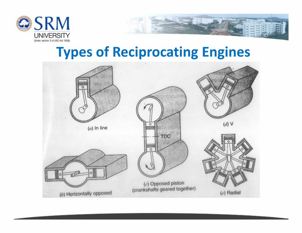
Types of Reciprocating Engines
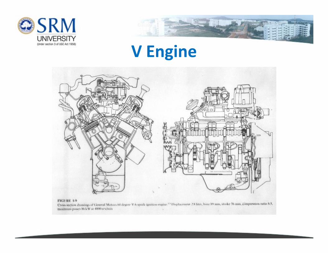
V Engine
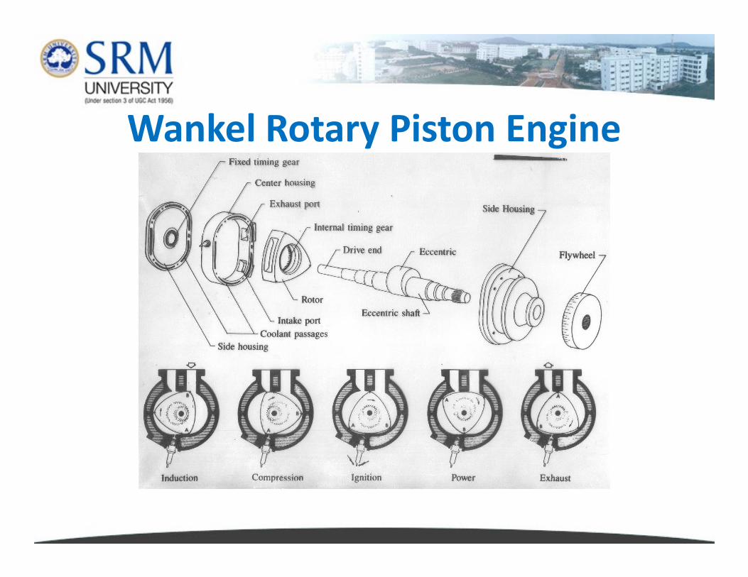
Wankel Rotary Piston Engine
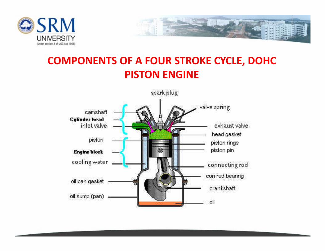
COMPONENTS OF A FOUR STROKE CYCLE, DOHC
PISTON ENGINE
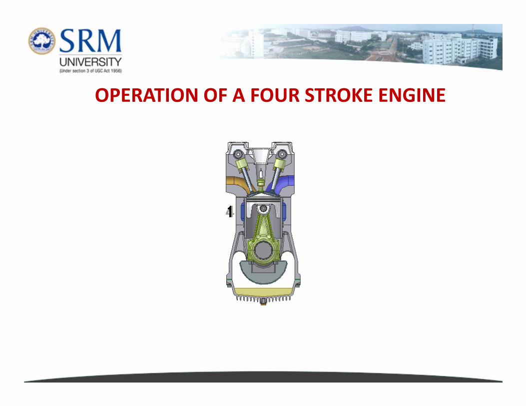
OPERATION OF A FOUR STROKE ENGINE
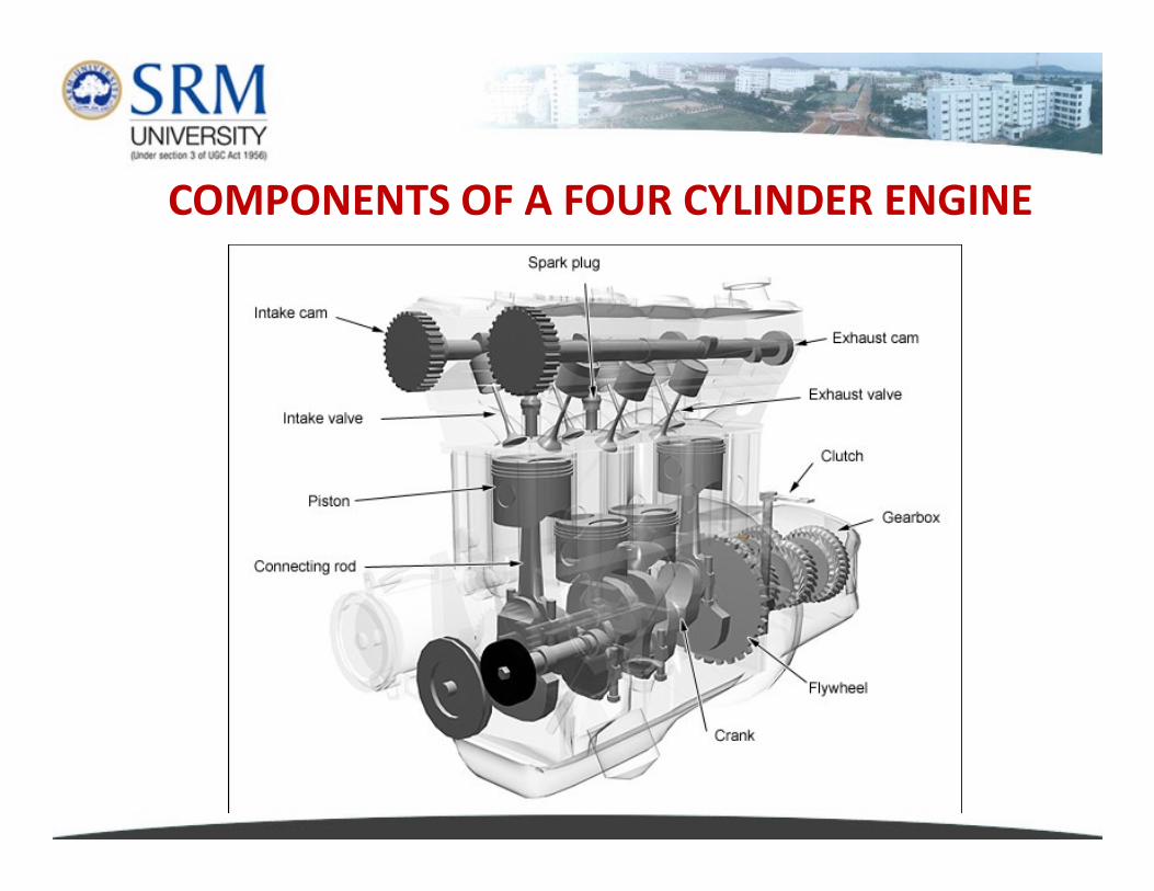
COMPONENTS OF A FOUR CYLINDER ENGINE
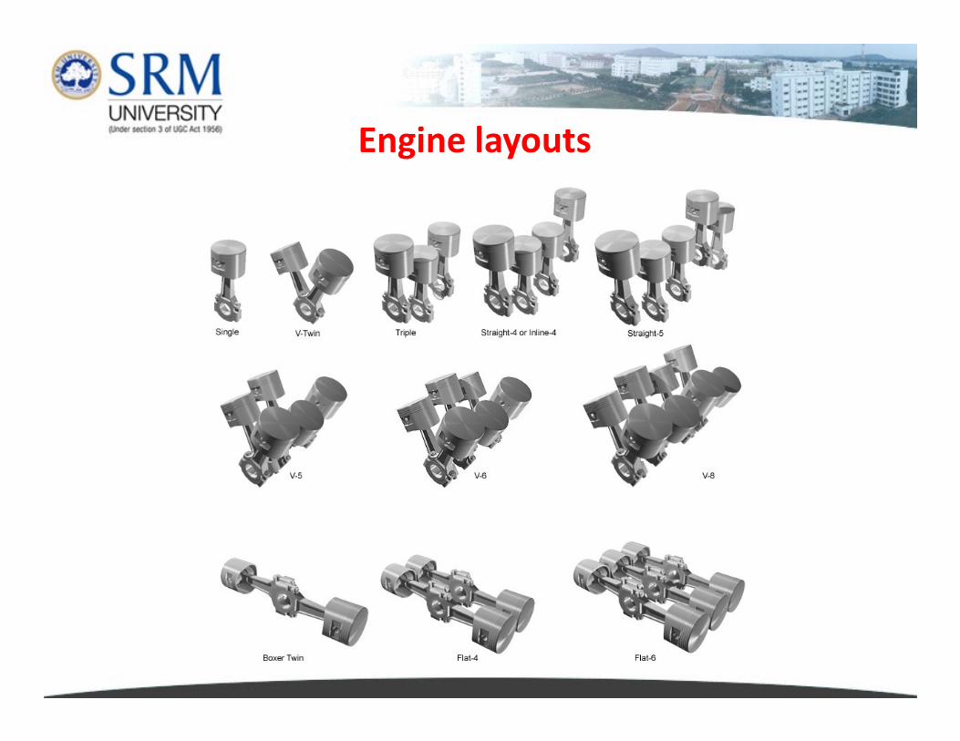
Engine layouts
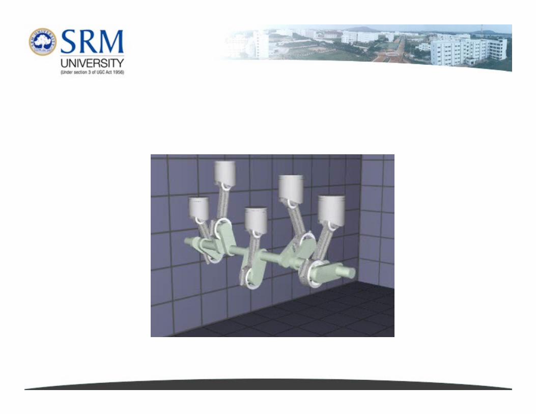
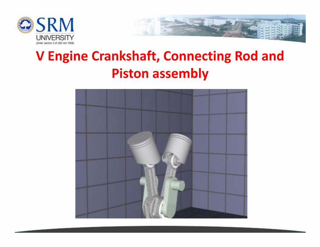
V Engine Crankshaft, Connecting Rod and
Piston assembly
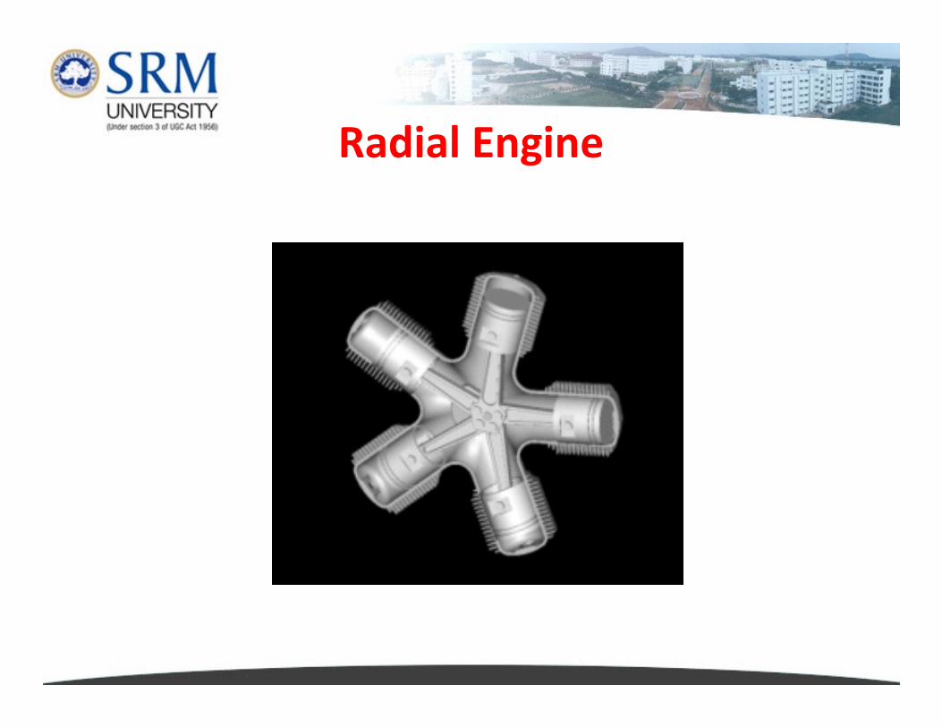
Radial Engine
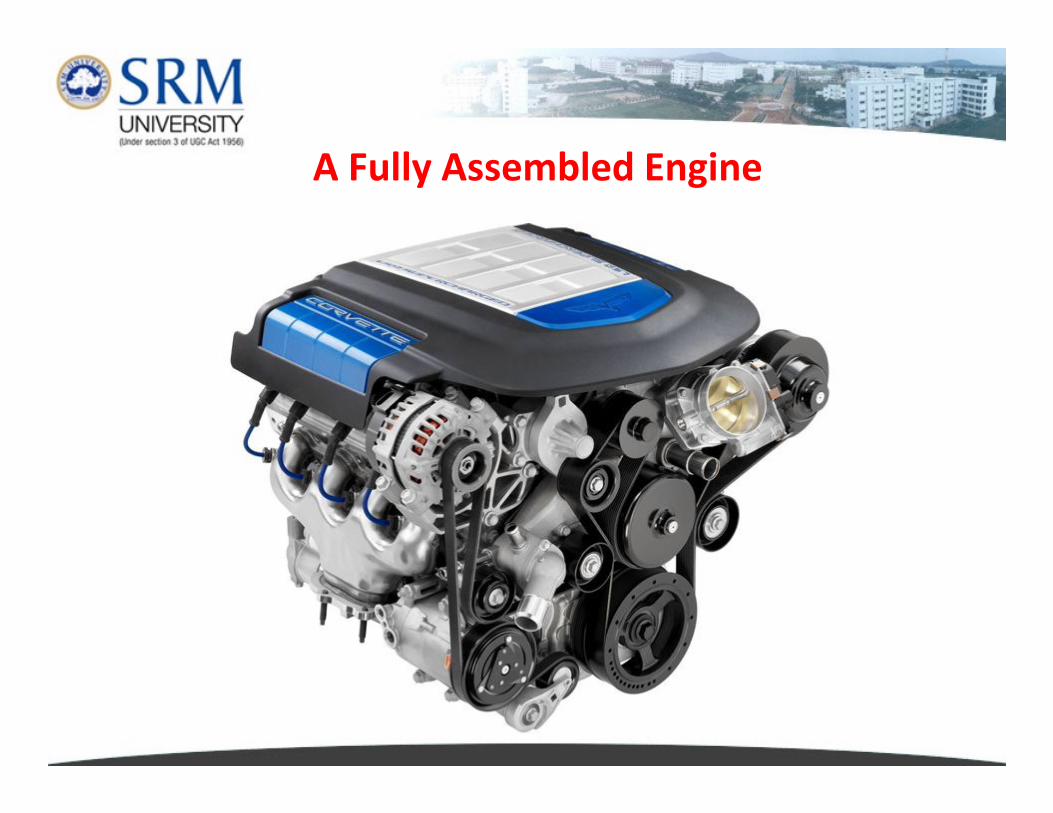
A Fully Assembled Engine
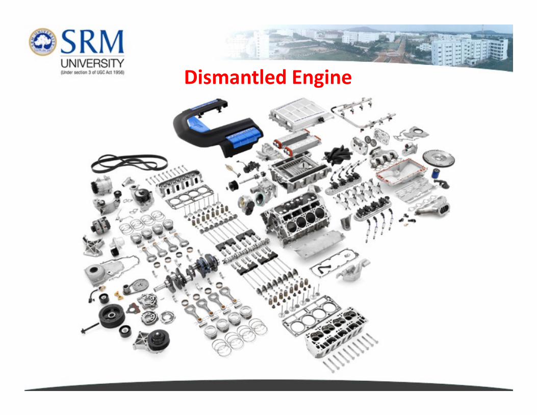
Dismantled Engine
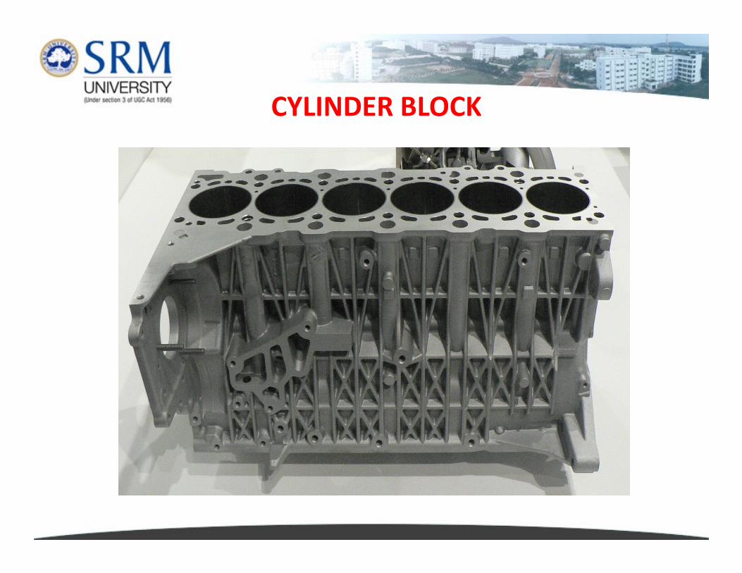
CYLINDER BLOCK
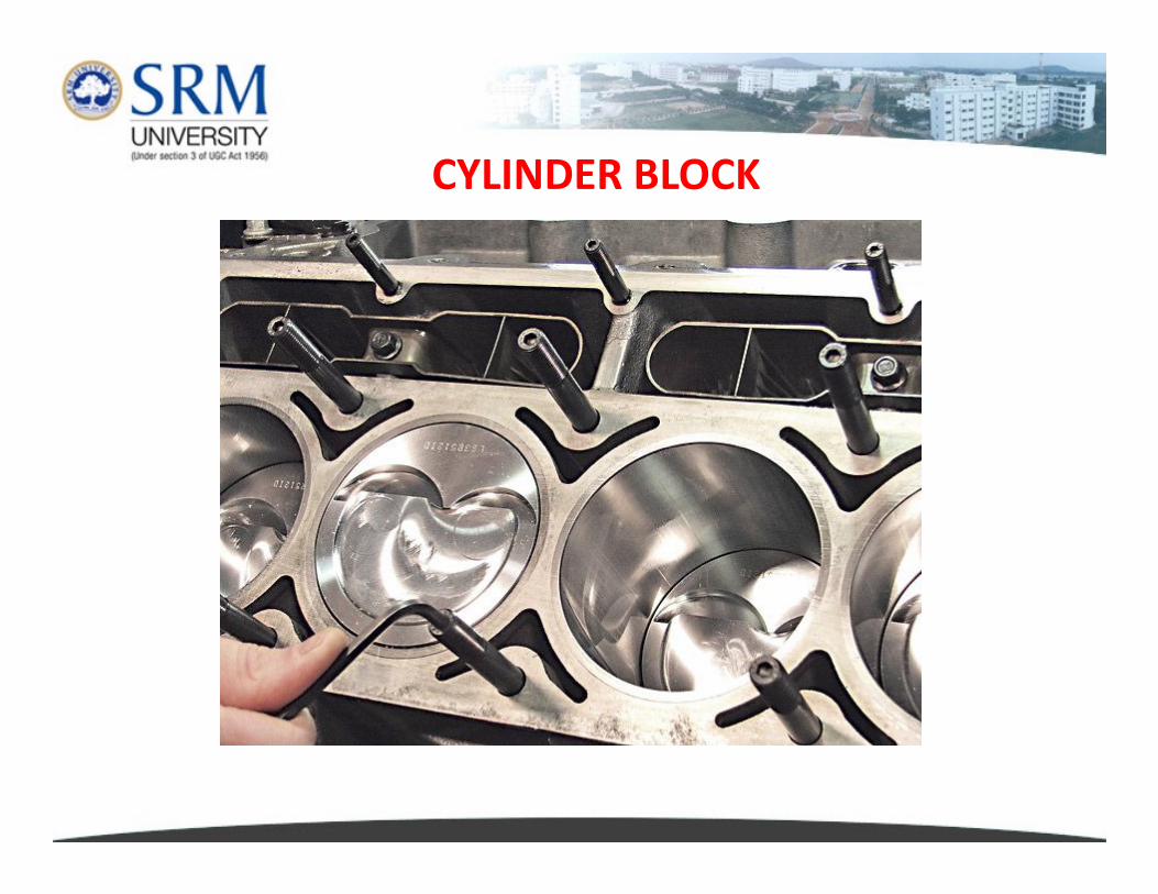
CYLINDER BLOCK
The cylinder block or engine block is a machined casting
containing cylindrically bored holes for the pistons of a
multi-cylinder reciprocating internal combustion engine.
It is a complex part at the heart of an engine, with
adaptions to attach the cylinder head, crankcase, engine
Cylinder block
adaptions to attach the cylinder head, crankcase, engine
mounts, drive housing and engine ancillaries, with
passages for coolants and lubricants.
Engine blocks are usually made from cast iron or, in
modern engines, aluminium and magnesium
CRANK CASE
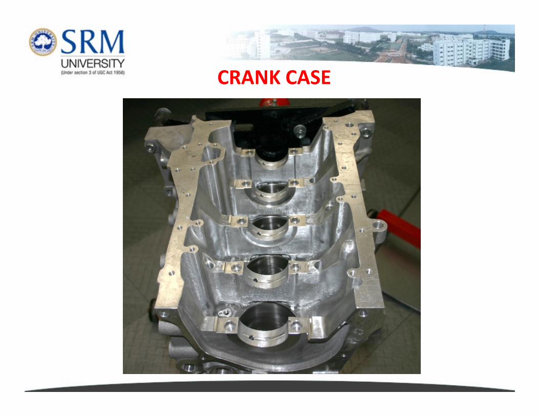
Crankcase is the housing for the crankshaft. The enclosure forms
the largest cavity in the engine and is located below the cylinder
block.
� It protects the crankshaft and connecting rods from foreign objects.
� In a four-stroke engine, the crankcase is filled mainly with air and oil,
and is sealed off from the fuel/air mixture by the pistons.
� In two-stroke gasoline engines, the crankcase is sealed and is used as � In two-stroke gasoline engines, the crankcase is sealed and is used as
a pressurization chamber for the fuel/air mixture. As the piston rises,
it pushes out exhaust gases and produces a partial vacuum in the
crankcase which aspirates fuel and air. As the piston travels
downward, the fuel/air charge is pushed from the crankcase and into
the cylinder.
� In two-stroke gasoline engines, the crankcase does not contain engine
oil because oil is mixed with the fuel, and the mixture provides
lubrication for the cylinder walls, crankshaft and connecting
rod bearings.
CYLINDER HEAD
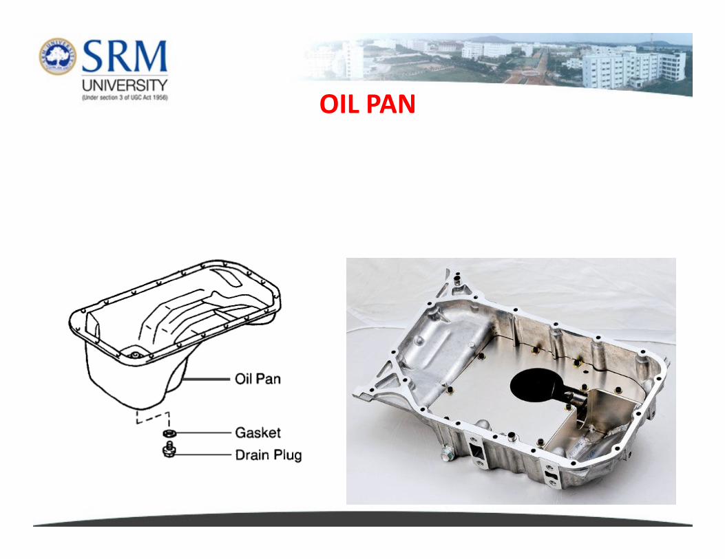
OIL PAN
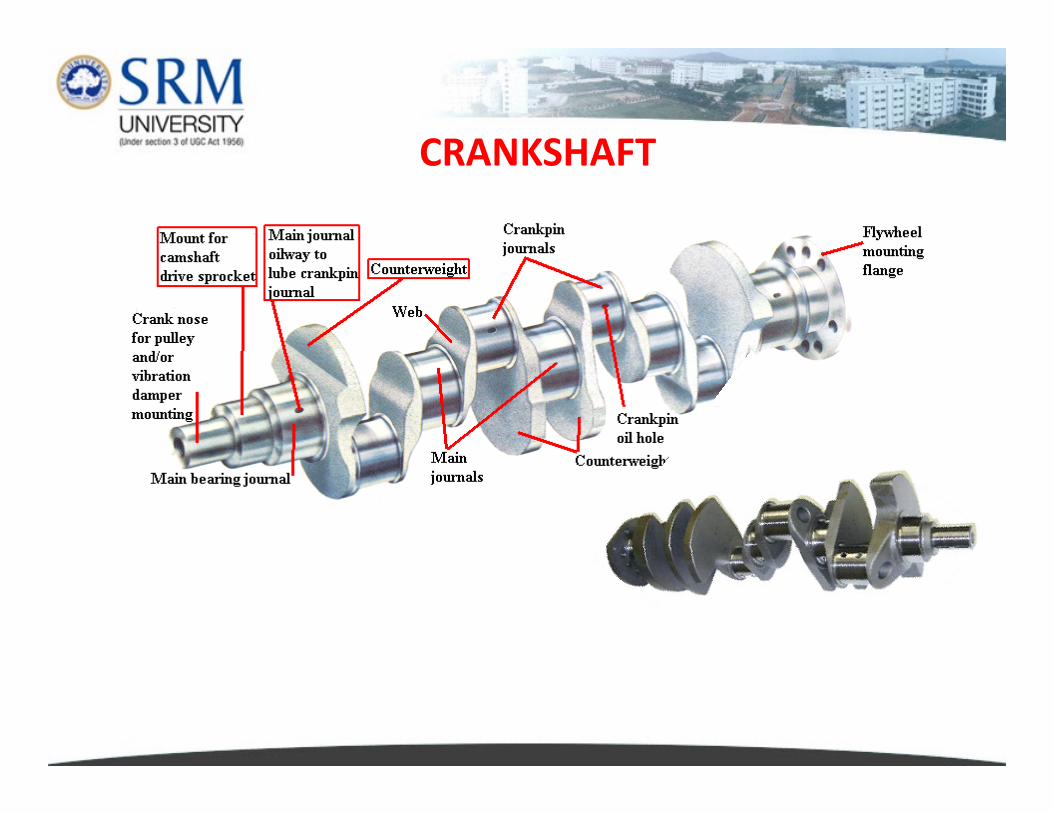
CRANKSHAFT
� Crankshaft is the main rotating shaft running the length of the
engine.
� The crankshaft is supported by Main bearings.
� Portions of the shaft are offset to form throws to which
the Connecting rods are attached.
� As the Pistons move up and down, the Connecting rods move � As the Pistons move up and down, the Connecting rods move
the crankshaft around.
� The turning motion of the crankshaft is transmitted to
the Transmission and eventually to the driving wheels.
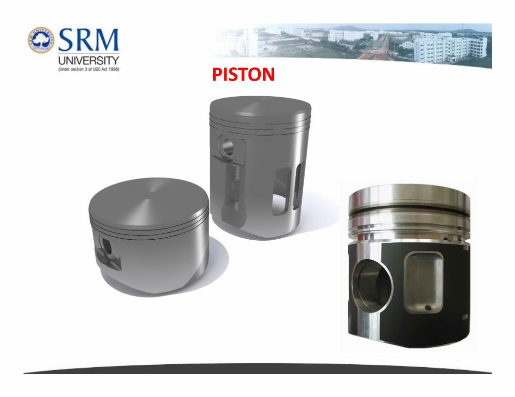
PISTON

• Constructed of aluminum alloy
• Parts include top, ring grooves,
ring lands, skirt, and piston pin
boss
Pistons
boss
• Cooling fins on the bottom help
the oil carry heat away from the
piston top
Piston must be made of a material that meets the following
requirements :
� Low Thermal expansion. The coefficient of thermal expansion
must be low. It is best to use the same material for both pistons
and cylinders.and cylinders.
�High heat conductivity.
� Low specific gravity (to decrease inertia during high
speed operation).
� Sufficient strength and large abrasion resistance even at high
temperatures.
�Easy to cast
� Alumunium alloys is currently used because they satisfy all of
the above requirements. Special cast iron is used as well.
� A piston made of special cast iron has the same coefficient of
thermal expansion as the cylinder, but tends to be heavy.
� Alumunium alloys has a larger coefficient of thermal expansion
than iron, but has high heat conductivity, therefore the
temperature of the piston head can be lowered.temperature of the piston head can be lowered.
� However, alumunium alloy has a weak point (poor lubricating oil
retention). For this reason, pistons are usually plated with lead
to eliminate this shortcoming.
� Seizure can be prevented by lead plating.
� Some pistons have a special cast iron ring carrier that is cast into
the top ring groove to prevent abrasion.
� A piston usually tin plated to improve initial breaking in
performance and to prevent rusting.
Thermal Problem of Pistons
The strength and hardness of the alumunium alloy used for manufacturing pistons
will suddenly decrease when temperature exceeds 400oC. As a result, abrasion and
cracking will begin to occur. When Lo-Ex alloy is used, the piston head cavity
temperature is designed to be 300 - 330oC and the bottom of the top of ring groove
is designed to below 230 - 250oC.
The overheating of piston can be prevented by various methods. For example the cooling
efficiency can be raised to lower the temperature of the cylinder liner. The thermal flow
type shape (dome shape that promotes the flow of heat from the top of the piston to the
ring) can be adopted for the back of pistons so that the piston temperature will be even.
Pistons can also be oil cooled.
When the piston is installed in the cylinder, there must be a specified clearance
between them. Insufficient clearance will cause seizure due to thermal
expansion, while excessive clearance will lead to compression leakage,
inefficient heat radiation by the piston, over-consumption of lubricating oil, and
piston slap.
Clearance between piston and cylinder
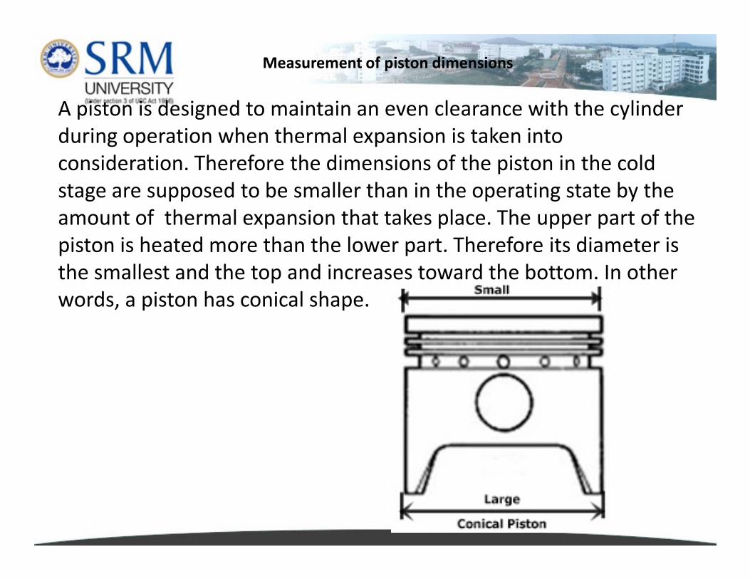
A piston is designed to maintain an even clearance with the cylinder
during operation when thermal expansion is taken into
consideration. Therefore the dimensions of the piston in the cold
stage are supposed to be smaller than in the operating state by the
amount of thermal expansion that takes place. The upper part of the
piston is heated more than the lower part. Therefore its diameter is
the smallest and the top and increases toward the bottom. In other
words, a piston has conical shape.
Measurement of piston dimensions
words, a piston has conical shape.

Since heat is transmitted through the ribs that connect the bosses of the piston head
and the piston pin, the ribs and bosses are heated more than the other parts. This mean
that the expansion in the axial direction of the piston is larger. Therefore the diameter in
the pin direction is smaller than the diameter in the perpendicular direction. (this called
Ovality)
Ovality
Ovality)
A cast iron piston is exactly round.
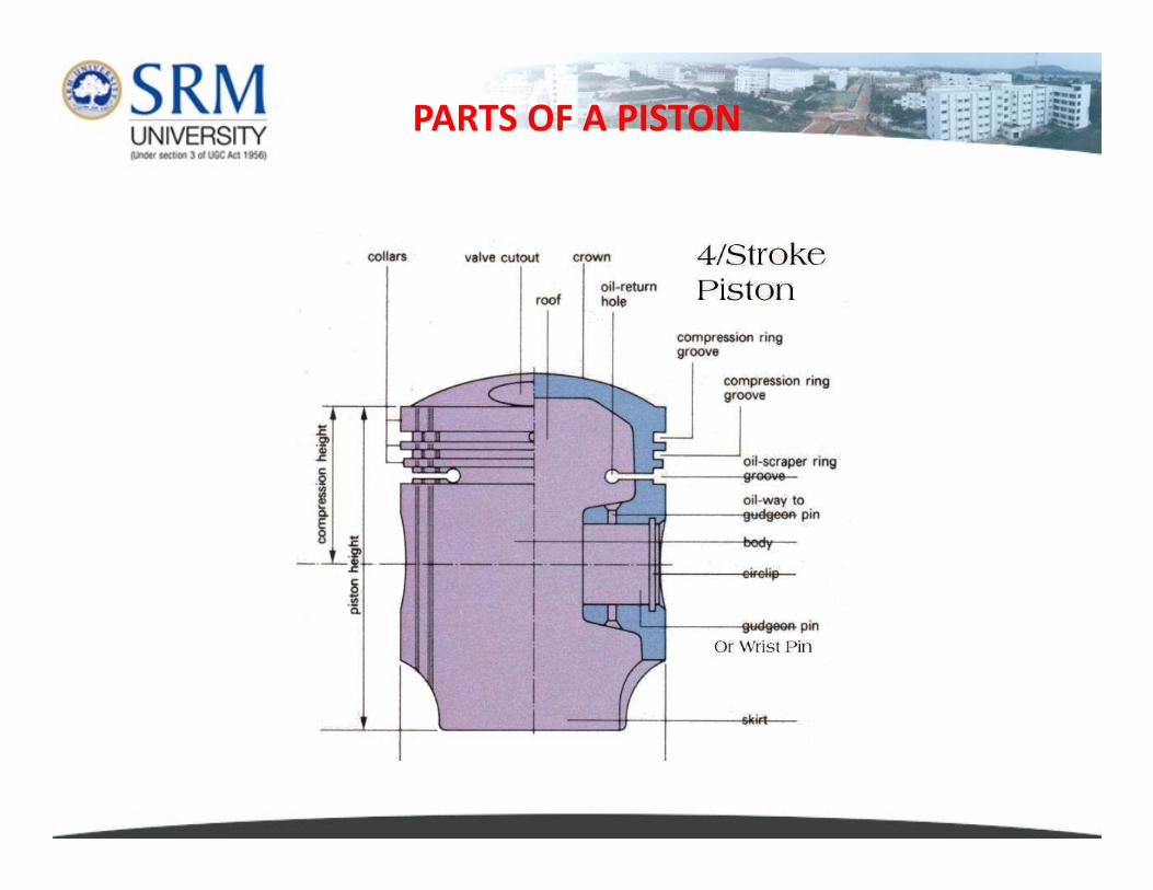
PARTS OF A PISTON
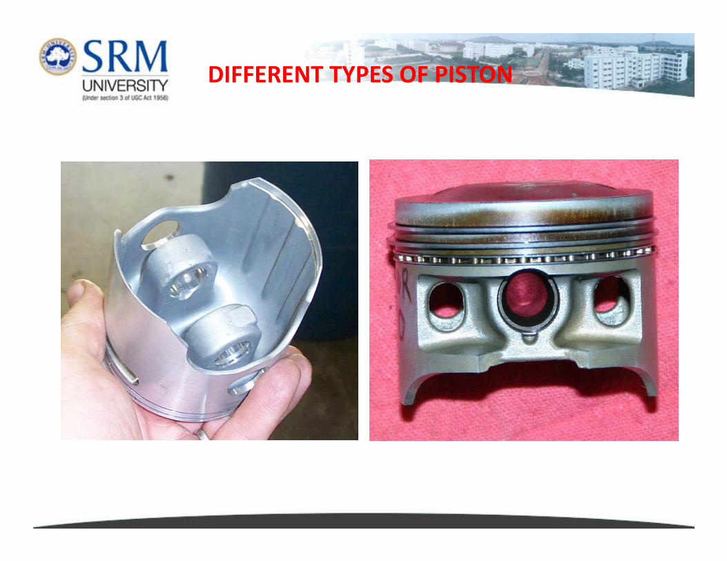
DIFFERENT TYPES OF PISTON

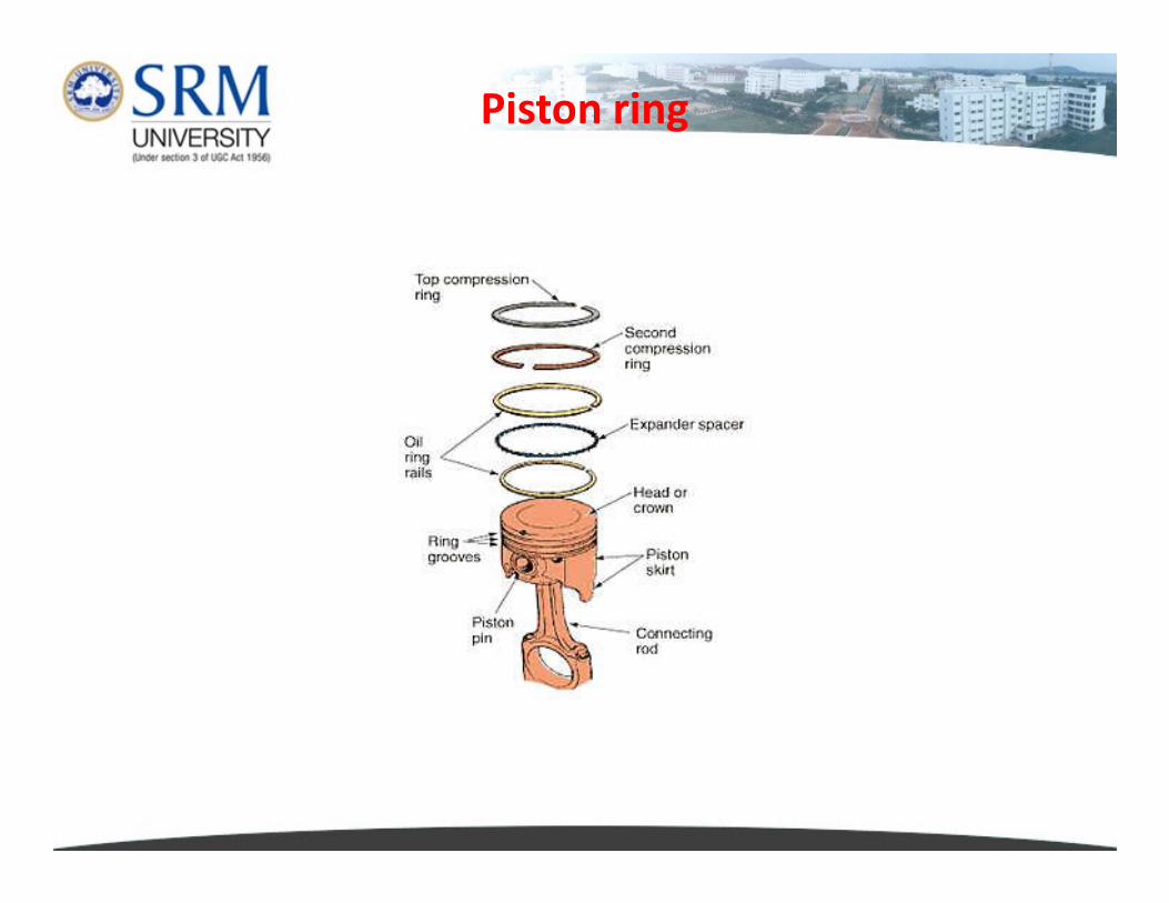
Piston ring
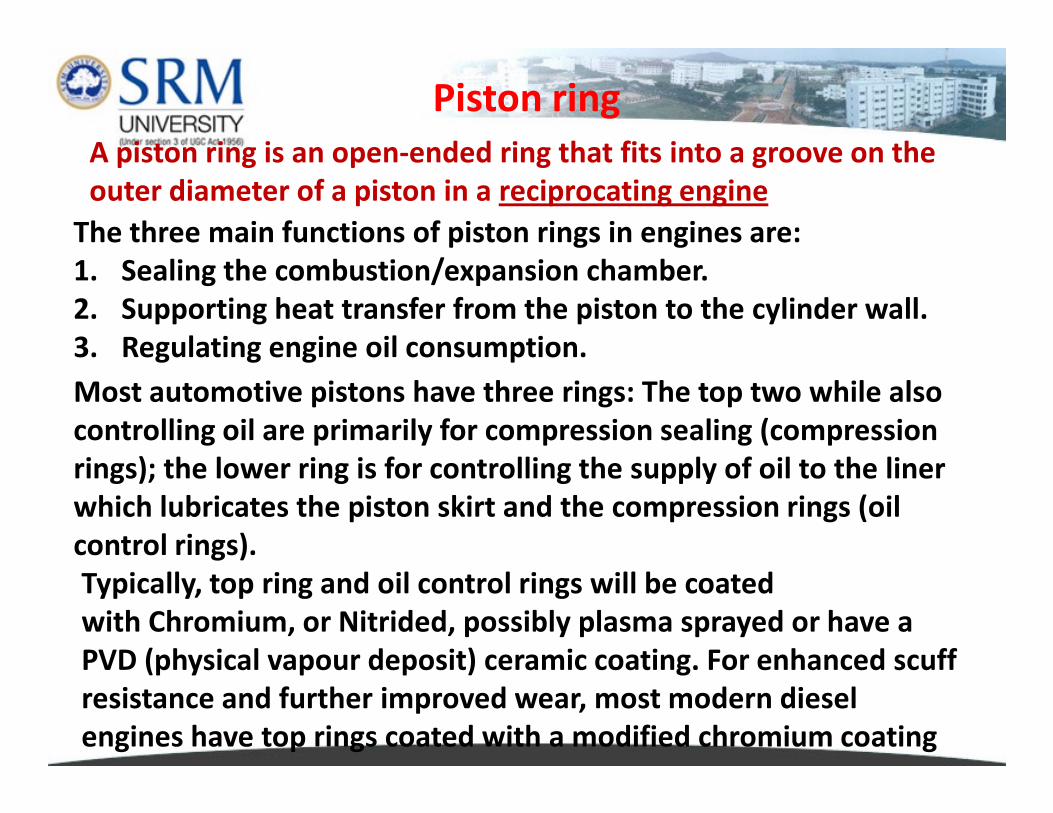
The three main functions of piston rings in engines are:
1. Sealing the combustion/expansion chamber.
2. Supporting heat transfer from the piston to the cylinder wall.
3. Regulating engine oil consumption.
A piston ring is an open-ended ring that fits into a groove on the
outer diameter of a piston in a reciprocating engine
Most automotive pistons have three rings: The top two while also
Piston ring
Most automotive pistons have three rings: The top two while also
controlling oil are primarily for compression sealing (compression
rings); the lower ring is for controlling the supply of oil to the liner
which lubricates the piston skirt and the compression rings (oil
control rings).
Typically, top ring and oil control rings will be coated
with Chromium, or Nitrided, possibly plasma sprayed or have a
PVD (physical vapour deposit) ceramic coating. For enhanced scuff
resistance and further improved wear, most modern diesel
engines have top rings coated with a modified chromium coating
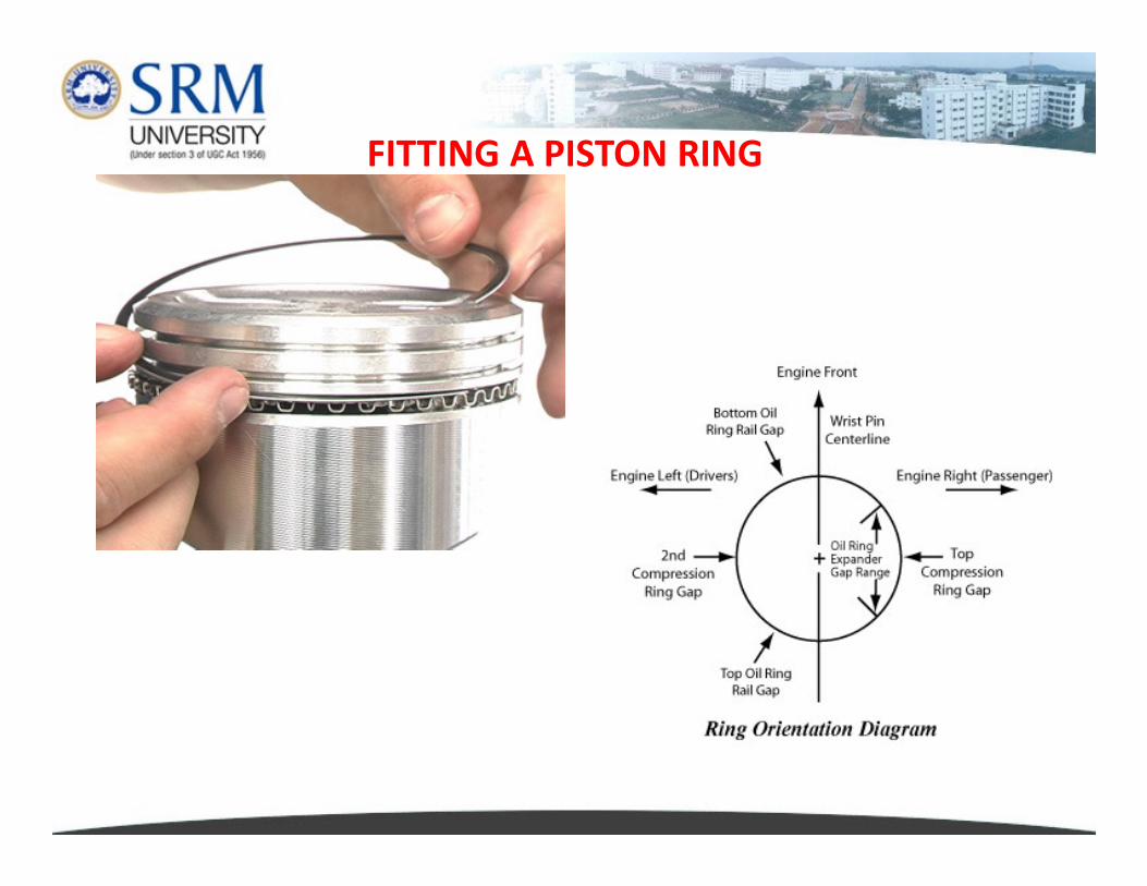
FITTING A PISTON RING
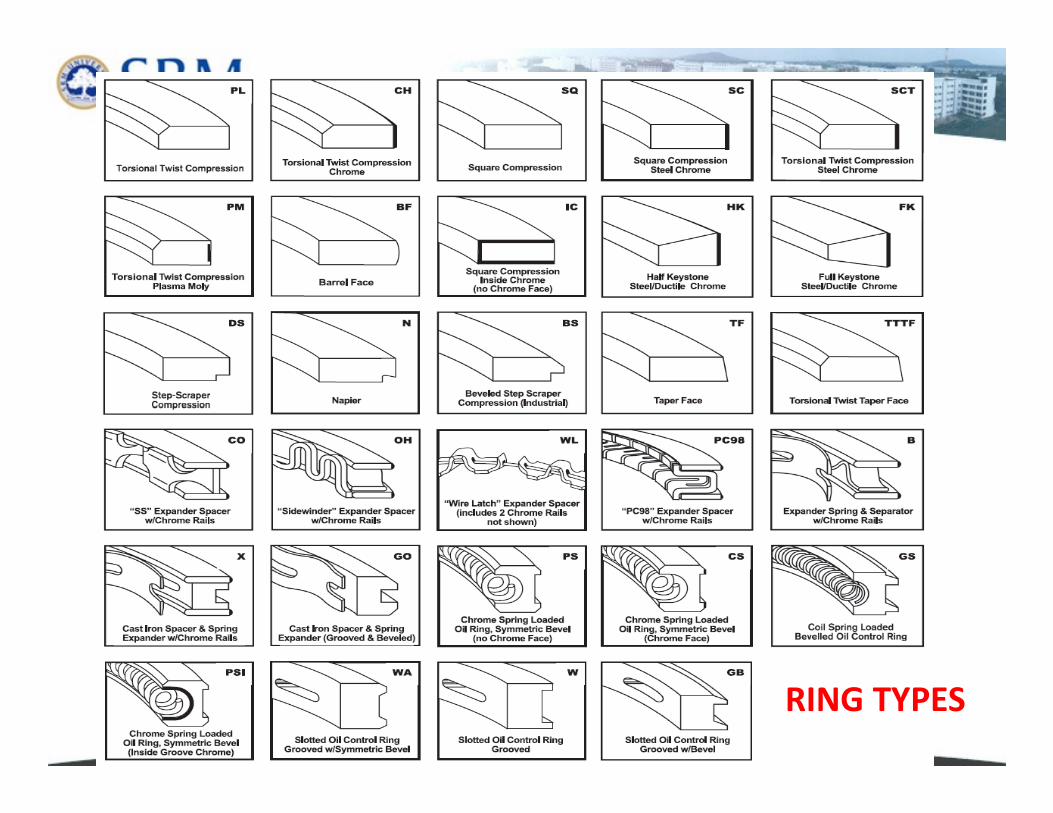
RING TYPES
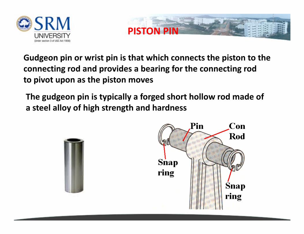
Gudgeon pin or wrist pin is that which connects the piston to the
connecting rod and provides a bearing for the connecting rod
to pivot upon as the piston moves
The gudgeon pin is typically a forged short hollow rod made of
a steel alloy of high strength and hardness
PISTON PIN
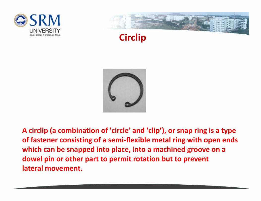
Circlip
A circlip (a combination of 'circle' and 'clip’), or snap ring is a type
of fastener consisting of a semi-flexible metal ring with open ends
which can be snapped into place, into a machined groove on a
dowel pin or other part to permit rotation but to prevent
lateral movement.
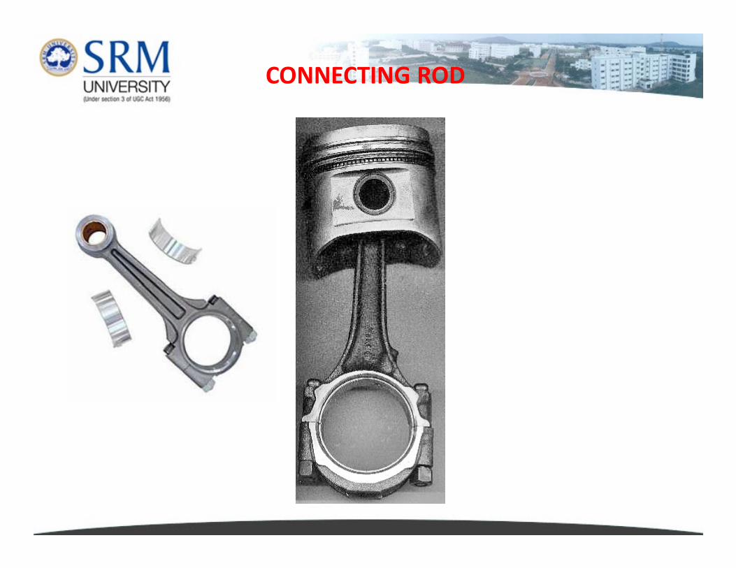
CONNECTING ROD
In a reciprocating piston engine, the connecting rod connects
the piston to the crankshaft. Together with the crank, they form
a simple mechanism that converts linear motion into rotating
motion.
CONNECTING ROD
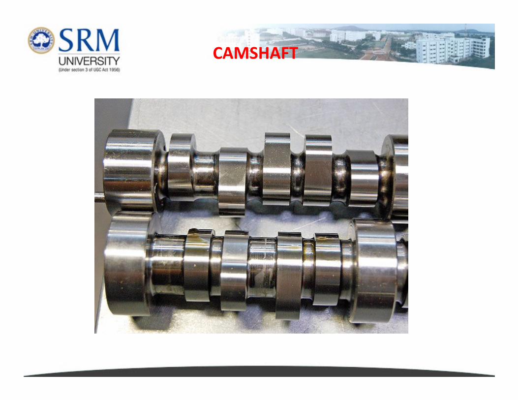
CAMSHAFT
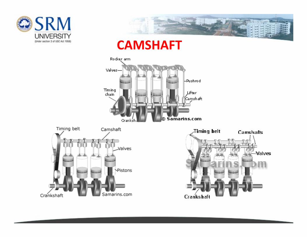
The camshaft is used to operate poppet valves. It then consists of
a cylindrical rod running the length of the cylinder bank with a
number of oblong lobes protruding from it, one for each valve.
The cams force the valves open by pressing on the valve, or on
some intermediate mechanism as they rotate.
CAMSHAFT
Chilled iron castings: this is a good choice for high volume
production. A chilled iron camshaft has a resistance against production. A chilled iron camshaft has a resistance against
wear because the camshaft lobes have been chilled, generally
making them harder.
Billet Steel: When a high quality camshaft is required, engine
builders and camshaft manufacturers choose to make the
camshaft from steel billet. This method is also used for low
volume production. This is a much more time consuming
process, and is generally more expensive than other methods.
However the finished product is far superior.
CAMSHAFT

DOHC
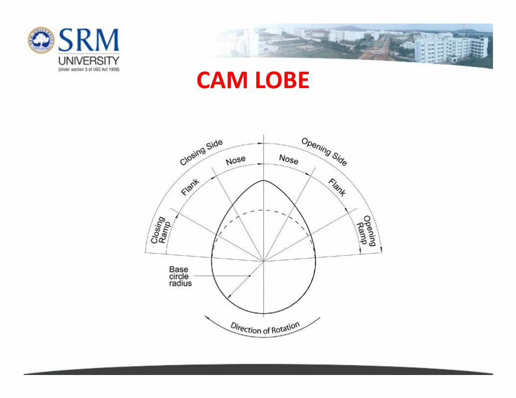
CAM LOBE
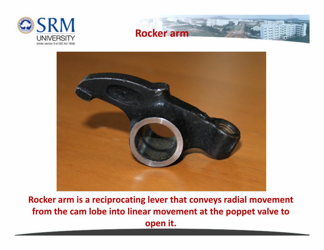
Rocker arm
Rocker arm is a reciprocating lever that conveys radial movement
from the cam lobe into linear movement at the poppet valve to
open it.
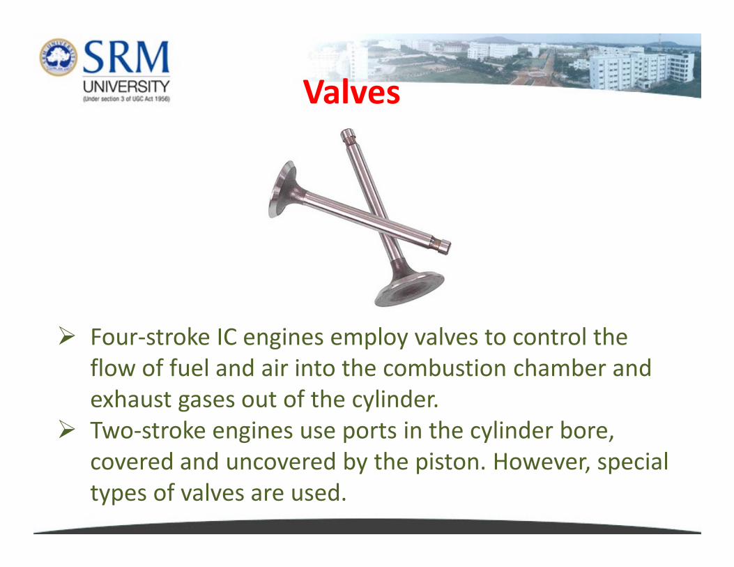
Valves
� Four-stroke IC engines employ valves to control the
flow of fuel and air into the combustion chamber and
exhaust gases out of the cylinder.
� Two-stroke engines use ports in the cylinder bore,
covered and uncovered by the piston. However, special
types of valves are used.
� Poppet valves are the most common and get their
name from the popping open and close during
operation.
� Intake valves are chrome steel and are cooled by the
incoming air and fuel mixture.
� Exhaust valves are also alloy steel but are often filled
Poppet valves
� Exhaust valves are also alloy steel but are often filled
with metallic sodium for cooling.
� Valve faces may be coated with Stellite to reduce wear
and corrosion.
� Stellite alloy is a range of cobalt-chromium alloy
designed for wear resistance. It may also contain
tungsten or molybdenum and a small but important
amount of carbon.
� The exhaust valves open against pressure within the
cylinder at the end of the working stroke where the
pressure is considerably higher.
� Further more, the pressure of the exhaust gases assists,
once the valve is open, in expelling the gasses through
Why exhaust valves are small?
once the valve is open, in expelling the gasses through
the open valve.
� Because of this consideration it is usual to find that
exhaust valves are designed to be of a smaller diameter
than the inlet valves.
� Being smaller also assists with keeping them cool which
is important as exhaust valves often give rise to thermal
problems.
Both the inlet and exhaust valve seats get damaged
during the operation and from time to time they
have to be reconditioned by grinding-in the valves.
This is required often for the exhaust valves
because they operate at higher temperatures and
Valve Rotation
because they operate at higher temperatures and
the exhaust gases contain carbon particles which
get trapped under the valve seat and cause pitting.
The life of an exhaust valve between reconditioning
can be extended if the thermal loads to which it is
subjected can be evenly distributed around the
valve. This is accomplished by the rotating the
valves slowly as the engine is working.
FOUR STROKE ENGINEFOUR STROKE ENGINE
FOUR STROKE ENGINE
�The four stroke engine was first demonstrated by Nikolaus Otto in 1876, hence the cycle of operation is called as the Otto cycle
�The technically correct term is Four Stroke �The technically correct term is Four Stroke (Cycle) Engine
�The four stroke engine is the most common type of engine used nowadays
�It powers almost all 2 wheelers, cars and trucks
The four strokes of the cycle are
1. Intake or Inlet
2. Compression
3. Power or Expansion
4. Exhaust
Each corresponds to one full stroke of the
piston, therefore the complete cycle
requires two revolutions of the crankshaft
to complete.
4. Exhaust
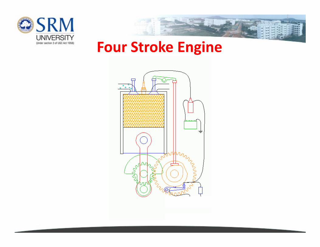
Four Stroke Engine
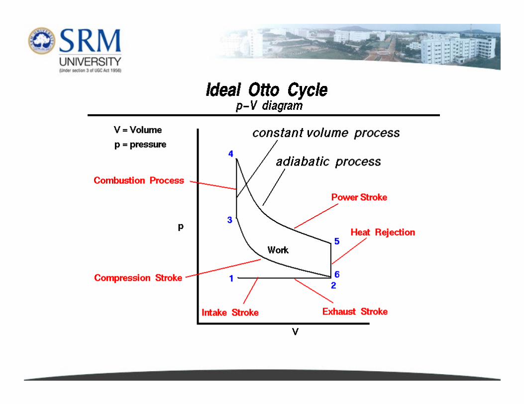
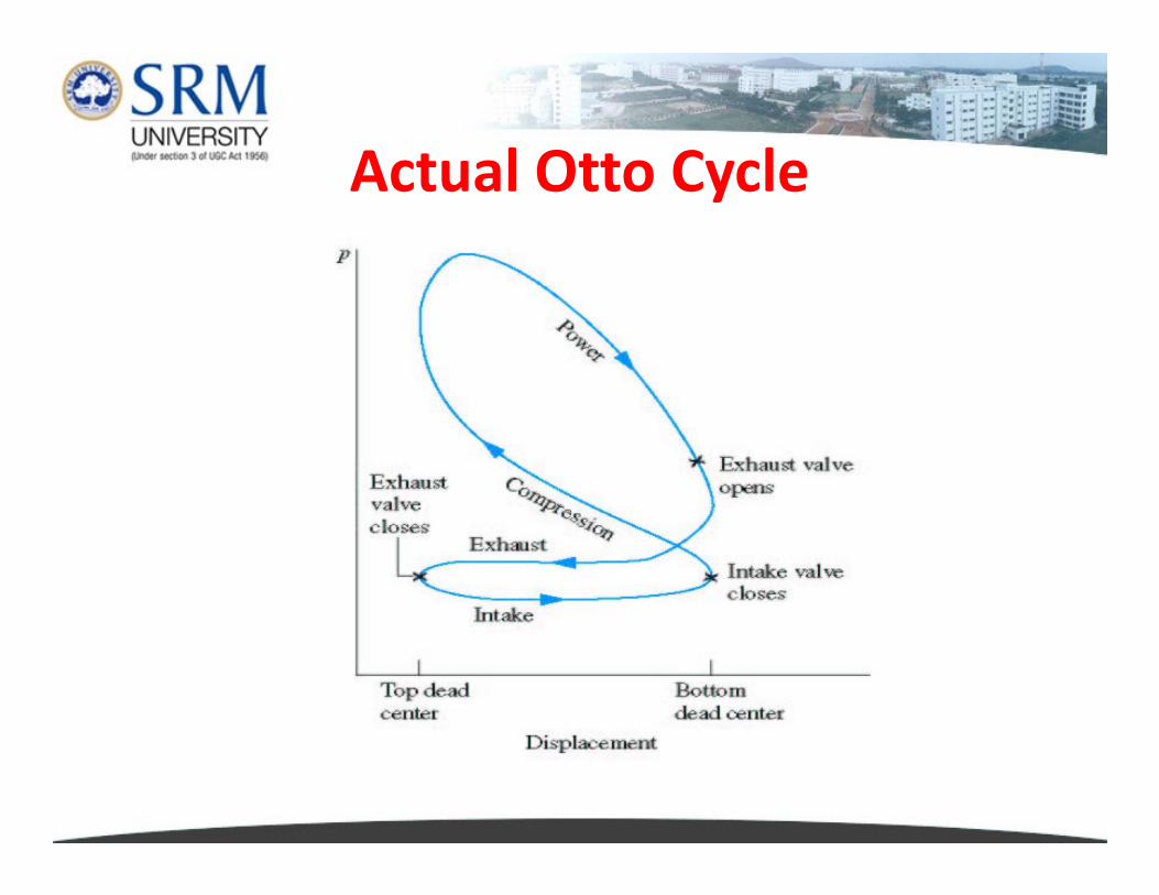
Actual Otto Cycle
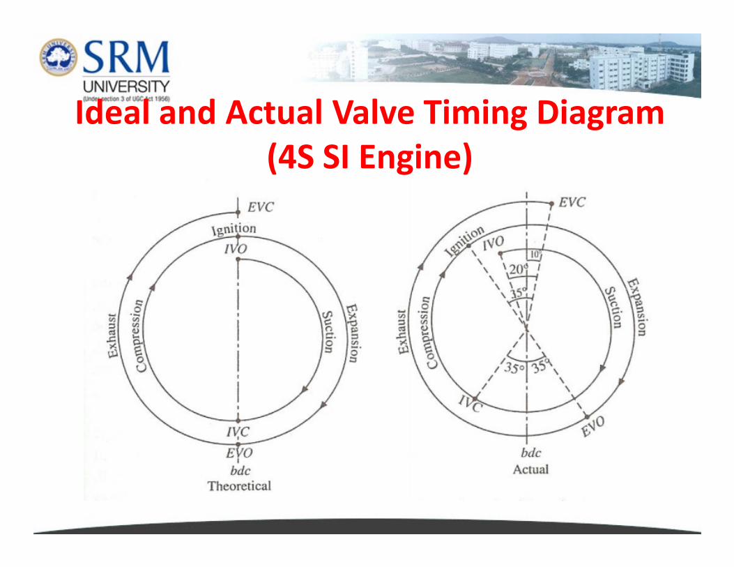
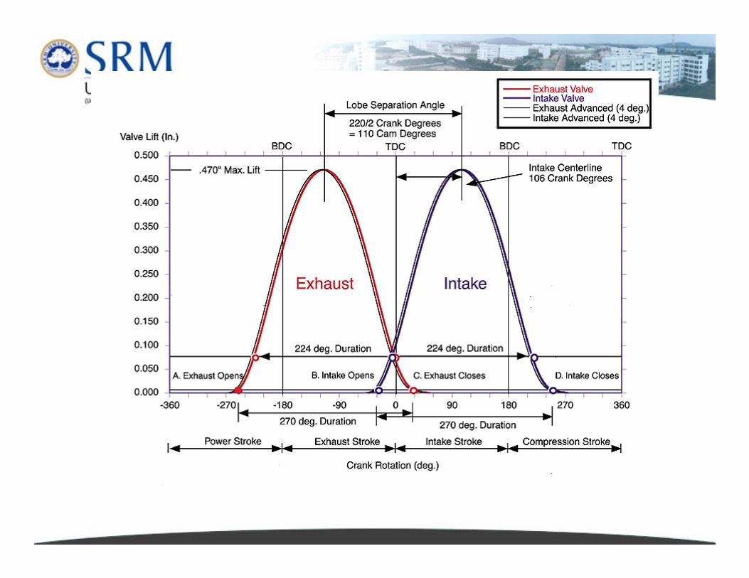
Ideal and Actual Valve Timing Diagram
(4S SI Engine)

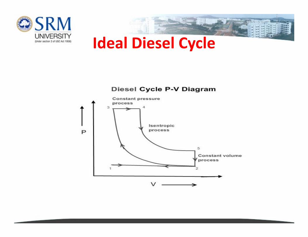
Ideal Diesel Cycle
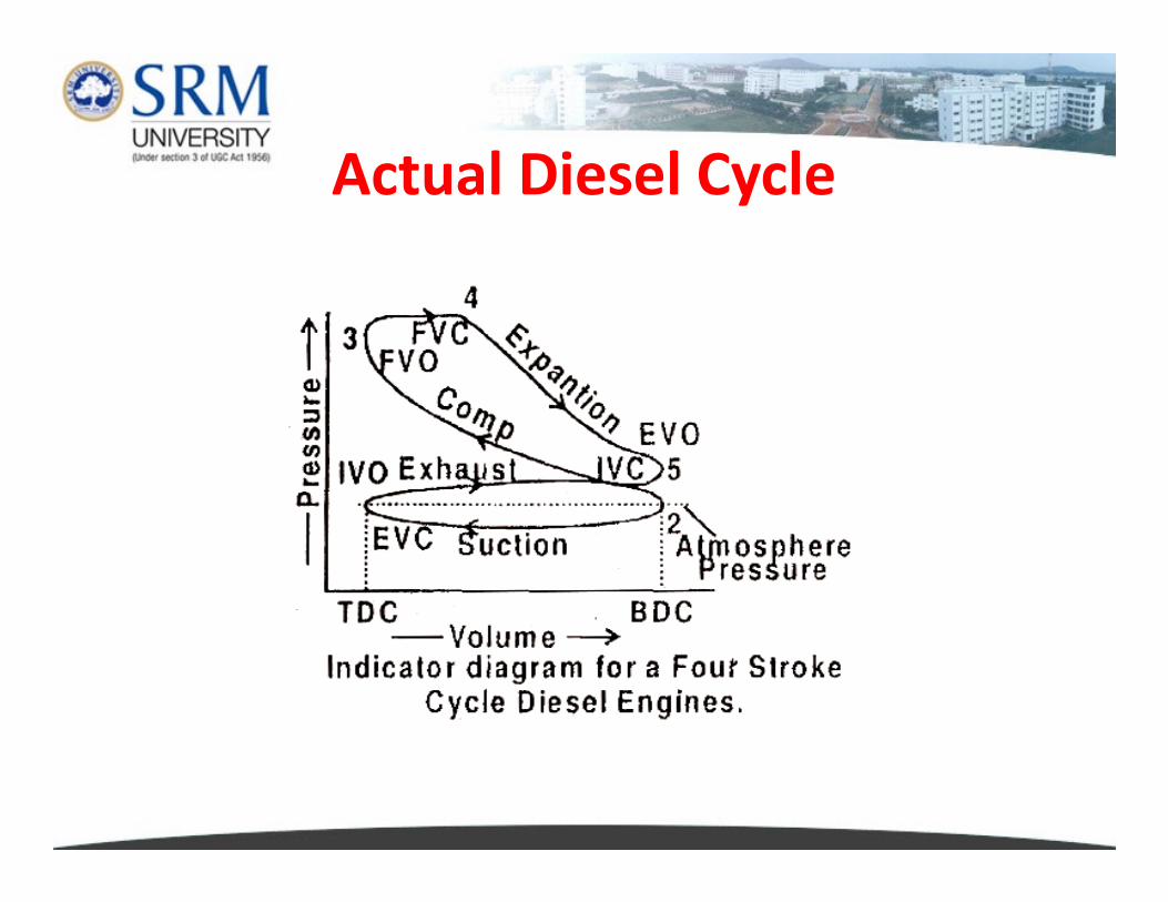
Actual Diesel Cycle
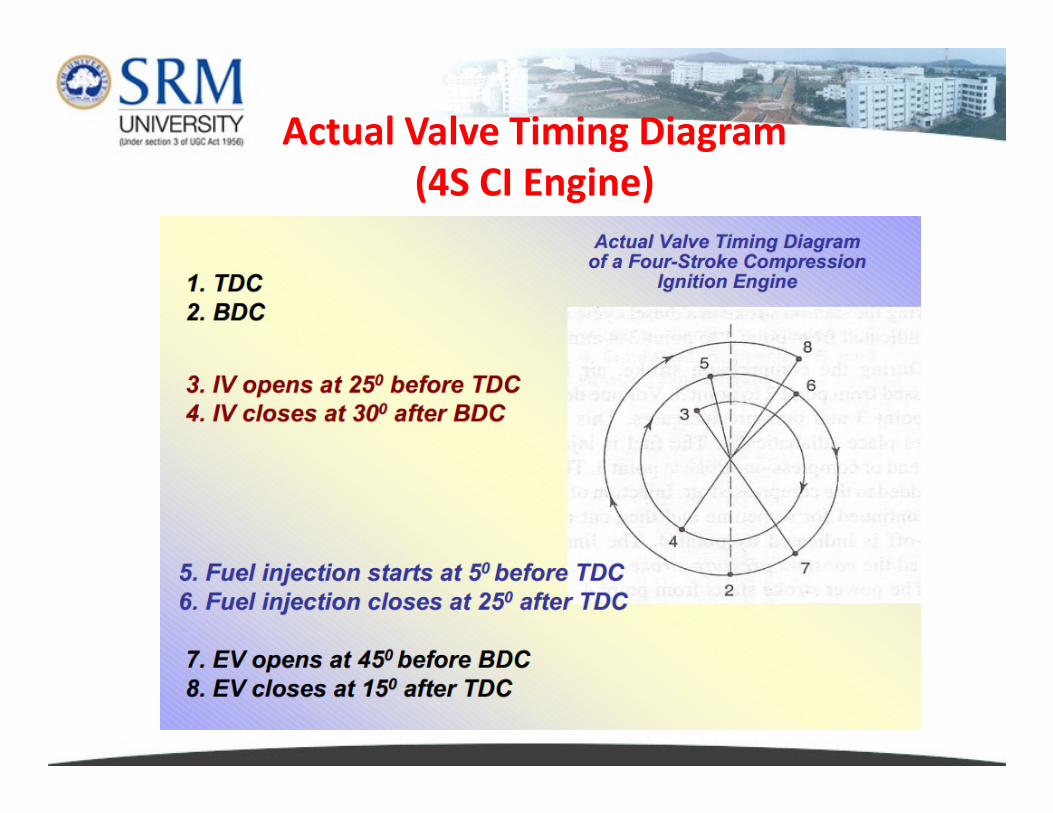
Actual Valve Timing Diagram
(4S CI Engine)
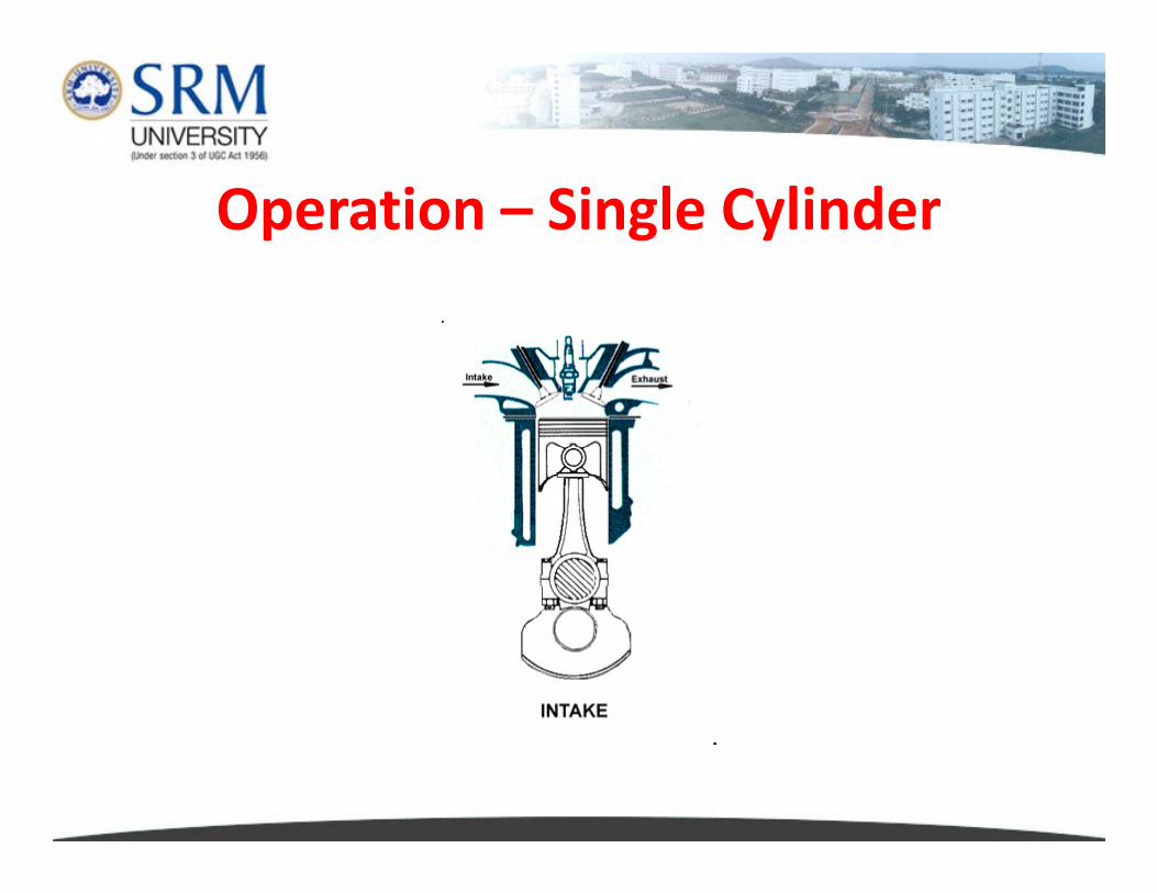
Operation – Single Cylinder
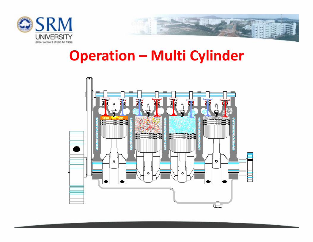
Operation – Multi Cylinder
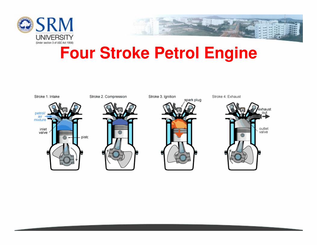
Four Stroke Petrol Engine
Intake Stroke
� Air-fuel mixture or Air is introduced to fill the
combustion chamber.
� Piston moves from TDC to BDC and the intake valve is
open.
� The movement of the piston toward BDC creates a low � The movement of the piston toward BDC creates a low
pressure in the cylinder.
� Ambient atmospheric pressure forces the air-fuel
mixture or air through the open intake valve into the
cylinder to fill the low pressure area created by the
piston movement.
Intake Stroke
� The cylinder continues to fill slightly after BDC also as
the air-fuel mixture continues to flow by its own inertia
while the piston begins to change direction.
� The intake valve remains open a few degrees of
crankshaft rotation after BDC. crankshaft rotation after BDC.
� Depending on engine design. The intake valve then
closes and the air-fuel mixture or air is sealed inside the
cylinder.
Compression Stroke� Trapped air-fuel mixture (called as charge) is compressed
inside the cylinder.
� Compression is the process of reducing or squeezing a
charge from a large volume to a smaller volume in the
combustion chamber. combustion chamber.
� Compressing the air-fuel mixture allows more energy to
be released when the charge is ignited.
� Intake and exhaust valves remain closed to ensure that
the cylinder is sealed to provide compression.
� The flywheel helps to maintain the momentum
necessary to compress the charge.
IGNITION - SI� The spark plug initiates combustion at approximately
20° of crankshaft rotation before TDC by a spark.
� The combustion starts when the charge gets ignited.
� Combustion is the rapid chemical reaction in which a
fuel chemically combines with oxygen in the mixture fuel chemically combines with oxygen in the mixture
and releases energy in the form of heat.
� During combustion a flame spreads throughout the
combustion chamber by a progressing flame front.
� A flame front is the boundary wall that separates the
charge from the combustion by-products.
� The flame front progresses across the combustion
chamber until the entire charge has burned.
� With both the inlet and the exhaust valves closed and
the piston about 23 deg BTDC diesel is injected into the
dense and heated air as a high-pressure spray of fine
particles.
� Proper atomization and distribution of fuel throughout
Fuel Injection - CI
� Proper atomization and distribution of fuel throughout
the air charge gets heated by the hot compressed air and
quickly vaporizes and ignites the tiny droplets of fuel.
� By this time, the piston reaches TDC and extensive
burning releases heat energy which is rapidly converted
into pressure energy.
� Expansion pushes the piston away from the cylinder
head.
Power Stroke
� The power stroke is the Stroke during which the hot
expanding gases force the piston towards the BDC
� Piston force and subsequent motion are transferred
through the connecting rod to apply torque to the
crankshaft. crankshaft.
� The torque applied initiates crankshaft rotation.
� The amount of torque produced is determined by the
pressure on the piston, the size of the piston, and the
throw of the engine.
� During the power Stroke, both valves remain closed.
Exhaust Stroke
� The exhaust stroke occurs when the burnt gases are
expelled from the combustion chamber to the
atmosphere.
� Piston reaches BDC during the end of power stroke
the cylinder is filled with exhaust gases, the exhaust the cylinder is filled with exhaust gases, the exhaust
valve opens, and inertia of the flywheel and other
moving parts push the piston back to TDC, forcing the
exhaust gases out through the open exhaust valve.
� At the end of the exhaust stroke, the piston is at TDC
and one operating cycle has been completed.
FIRING ORDERFIRING ORDER
� Front of the engine is the part where the pulleys for the
accessories (alternator and water pump) are, and rear
of the engine is where the flywheel, through which the
engine connects to the transmission.
� The front of the engine may point towards the front,
CYLINDER NUMBERING
� The front of the engine may point towards the front,
side or rear of the car.
� In most rear-wheel drive cars, the engine
is longitudinally mounted and the front of the engine
also points to the front of the car.
� In front-wheel drive cars with a transverse engine, the
front of the engine usually points towards the right-
hand side of the car.
�In front-wheel-drive cars with longitudinally
mounted engines, most often the front of the engine
will point towards the front of the car, but some
manufacturers (Saab, Citroën, Renault) have at times
CYLINDER NUMBERING
manufacturers (Saab, Citroën, Renault) have at times
placed the engine 'backwards', with #1 towards the
firewall.
� In a V engine, cylinder numbering varies among
manufacturers.
� Generally, the most forward cylinder is numbered 1
� Some manufacturers continue numbering along that
CYLINDER NUMBERING – V ENGINES
� Some manufacturers continue numbering along that
bank first, so that one side of the engine would be 1-2-
3-4, and the opposite bank would be 5-6-7-8.
� Others will number the cylinders from front to back
along the crankshaft, so one bank would be 1-3-5-7
and the other bank would be 2-4-6-8.
FIRING ORDER� The firing order is the sequence of power delivery of
each cylinder in a multi-cylinder reciprocating engine.
� This is achieved by spark plugs sparking in a SI engine in
the correct order, or by the sequence of fuel injection in
a CI engine. a CI engine.
� Choosing an appropriate firing order is critical to
� Minimise vibration
� To improve engine balance
� Achieve smooth running
� Long engine fatigue life
� User comfort
� Firing Order heavily influences crankshaft design.
FIRING ORDER
1-3-2 – 3 Cylinder Engine
1-3-4-2 – Most Common Four Cylinder Engine
1-5-3-7-4-8-2-6 – V8 Ferrari
1-6-5-10-2-7-3-8-4-9 – V101-6-5-10-2-7-3-8-4-9 – V10
TWO STROKE ENGINE
� The second type of Internal Combustion Engine
operates on the Two Stroke Cycle
� This engine was invented by Dugald Clerk (1854-
1932), a British Engineer in the year 18801932), a British Engineer in the year 1880
� Two stroke engine have no valves
� They don’t have camshaft, cams, springs and other
valve train elements
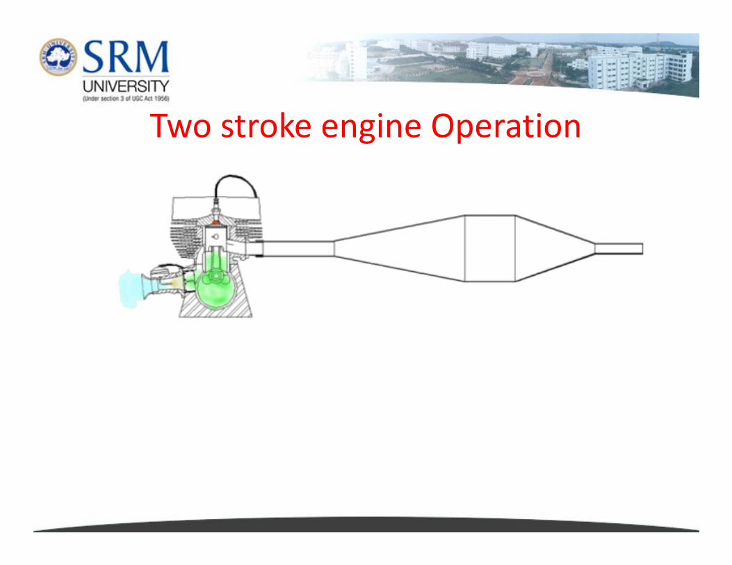
Two stroke engine Operation
TWO STROKE ENGINE
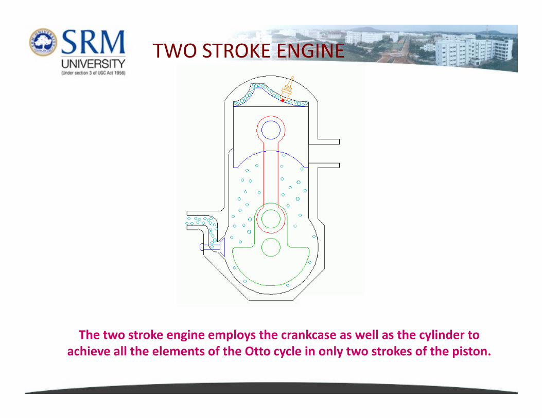
The two stroke engine employs the crankcase as well as the cylinder to
achieve all the elements of the Otto cycle in only two strokes of the piston.
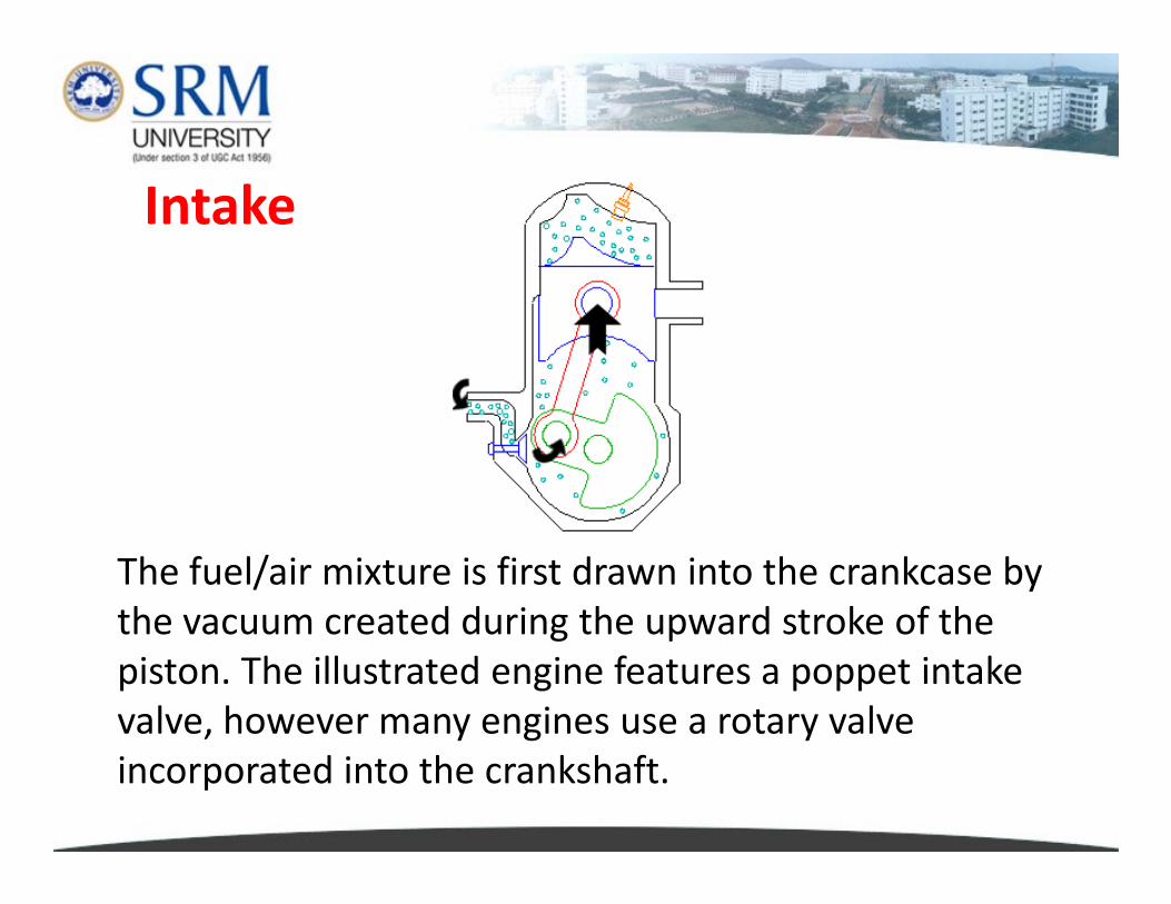
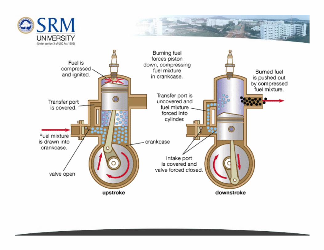
Intake
The fuel/air mixture is first drawn into the crankcase by
the vacuum created during the upward stroke of the
piston. The illustrated engine features a poppet intake
valve, however many engines use a rotary valve
incorporated into the crankshaft.
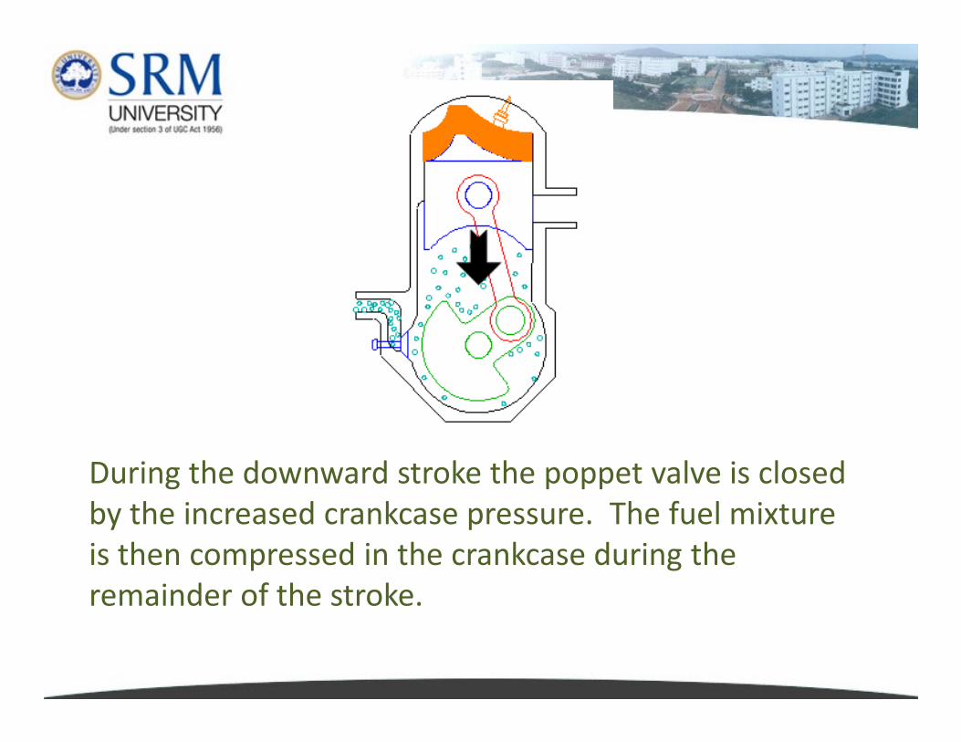
During the downward stroke the poppet valve is closed
by the increased crankcase pressure. The fuel mixture
is then compressed in the crankcase during the
remainder of the stroke.
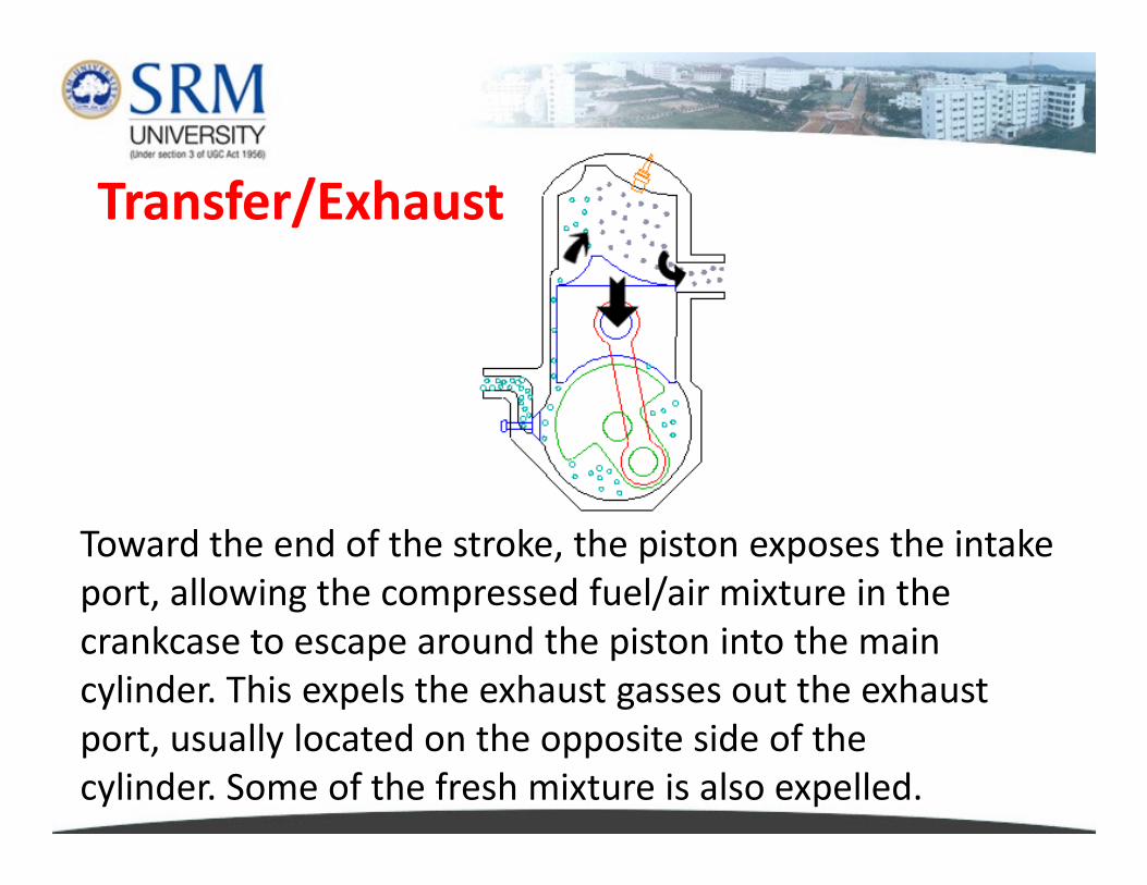
Transfer/Exhaust
Toward the end of the stroke, the piston exposes the intake
port, allowing the compressed fuel/air mixture in the
crankcase to escape around the piston into the main
cylinder. This expels the exhaust gasses out the exhaust
port, usually located on the opposite side of the
cylinder. Some of the fresh mixture is also expelled.
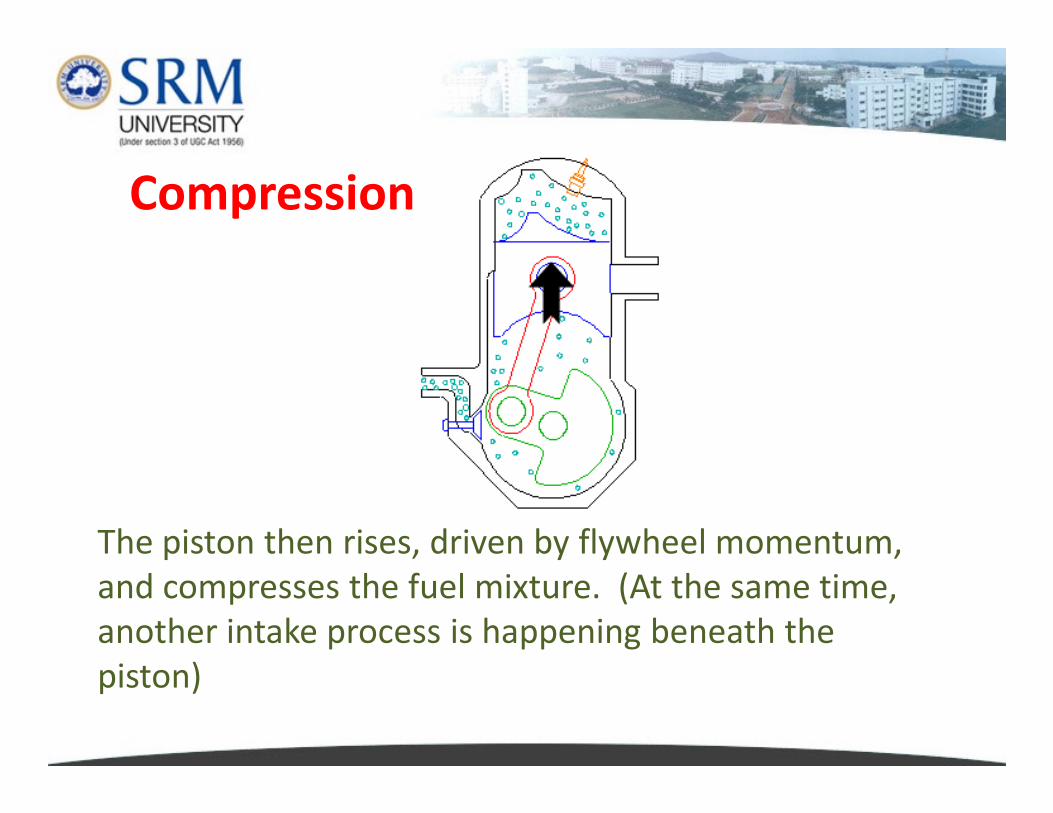
Compression
The piston then rises, driven by flywheel momentum,
and compresses the fuel mixture. (At the same time,
another intake process is happening beneath the
piston)

Power
At the top of the stroke the spark plug ignites the fuel
mixture. The burning fuel expands, driving the piston
downward, to complete the cycle.
� Since the two stroke engine fires on every revolution of
the crankshaft, they are more powerful than a four
stroke engine of equivalent size.
� This, coupled with their lighter, simpler construction,
makes them popular in light motorcycles, chainsaws,
line trimmers, outboard motors, snowmobiles, line trimmers, outboard motors, snowmobiles,
and model airplanes.
� Unfortunately, two stroke engines are inefficient and
pollutes heavily due to the amount of unburnt fuel
that escapes through the exhaust port.