advisory of transportation u.s,department circular system (eicas) message, master caution) must...
TRANSCRIPT

u.s, Departmentof Transportation
Federal AviationAdministration
AdvisoryCircular
AC No: 25.1322-1Subject: FLlGHTCREW ALERTING Date: 12/13/2010Initiated By: ANM-IOO
This advisory circular (Ae) provides guidance for showing compliance with certainrequirements of Title 14 of the Code of Federal Regulations (14 CFR), part 25, for the design
~"-"~'-.-''""'
Ali BahramiManager, Transport Airplane DirectorateAircraft Certification Service

12/13/2010 AC 25.1322-1
Table of Contents
Paragraph .................................................................................................................Page Number
1. Purpose...................................................................................................................................... 4
4
4
5
77
888
9
101011
11
12
12
14
16
16
17
2. Applicability .............................................................................................................................
3. Related Examples, Regulations, Documents, and Definitions .............................................
4. Background .............................................................................................................................. 5
5. Designing a Flightcrew-Alerting System ...............................................................................
a. General.................................................................................................................................. 5 b. Flightcrew-Alerting Philosophy ......................................................................................... 5 c. Design Considerations ......................................................................................................... 5
6. Alert Functional Elements ......................................................................................................
a. Warning Alerts..................................................................................................................... b. Time-Critical Warning Alerts ............................................................................................ 7 c. Master Visual and Aural Alerts.......................................................................................... d. Caution Alerts ...................................................................................................................... e. Advisory Alerts.....................................................................................................................
7. Alerting System Reliability and Integrity.............................................................................. 9
8. Managing Alerts.......................................................................................................................
a. Rules and General Guidelines........................................................................................... 10 b. Multiple Aural Alerts ........................................................................................................ c. Multiple Visual Alerts........................................................................................................ d. Alert Inhibits ......................................................................................................................
9. Clearing and Recalling Visual Alert Messages ...................................................................
10. Interface or Integration with Other Systems (Checklist, Synoptics, Switches, Discrete lamps). ..........................................................................................................................................
11. Color Standardization .........................................................................................................
12. Minimizing the Effects of False and Nuisance Alerts ....................................................... 14
13. Showing Compliance for Approval of a Flightcrew-Alerting System.............................
14. Integrating Flightcrew-Alerting System Elements into the Existing Fleet.....................
a. General................................................................................................................................ b. Visual Alerts ....................................................................................................................... 17 c. Aural Alerts ........................................................................................................................
2

12/13/2010 AC 25.1322-1
d. Tactile Alerts ...................................................................................................................... 17
1715. Alerts for Head-Up Displays (HUDs).................................................................................
List of Appendices
Appendix 1 Examples for Including Visual System Elements in an Alerting System.... A1-1
Appendix 2 Examples for IncludingAural System Elements in an Alerting Syste, ......... A2-1
Appendix 3 Regulations......................................................................................................... A3-1
Appendix 4 Related Documents............................................................................................ A4-1
Appendix 5 Definitions .......................................................................................................... A5-1
3
12/13/2010 AC 25.1322-1
1. Purpose. This advisory circular (AC) provides guidance for showing compliance with certain requirements of Title 14, Code of Federal Regulations (14 CFR), part 25, for the design approval of flightcrew-alerting functions. This AC addresses the type of alert function elements that should be considered (including visual, aural, and tactile or haptic elements), alert management, interface or integration of alerts with other systems, and color standardization. The appendices to this AC also provide examples for including visual and aural system elements in an alerting system.
2. Applicability.
a. The guidance provided in this document is applicable to airplane manufacturers, modifiers, avionics manufacturers, Federal Aviation Administration (FAA) transport airplane type certification engineers, human factor specialists, test pilots and their designees.
b. This guidance is applicable to new airplanes. It may also be applicable to modified airplanes and to integrating flightcrew alerting system elements into existing airplanes. It applies to individual aircraft systems that provide flightcrew-alerting functions that may or may not be integrated with a central alerting system, as well as to systems whose primary function is alerting, such as a central alerting system.
c. Like all AC material, this AC is not, in itself, mandatory, and does not constitute a regulation. It describes an acceptable means, but not the only means, for showing compliance with the requirements for transport category airplanes. The FAA will consider other methods of showing compliance that an applicant may elect to present. While these guidelines are not mandatory, we derived them from extensive FAA and industry experience in showing compliance with the relevant regulations. On the other hand, if we become aware of circumstances that convince us that following this AC would not result in compliance with the applicable regulations, we will not be bound by the terms of this AC. We may require additional substantiation or design changes as a basis for finding compliance.
d. This material does not change, create any additional, authorize changes in, or permit deviations from, regulatory requirements.
e. The term “must” in this AC, is used only in the sense of ensuring applicability of this
particular method of compliance when the acceptable method of compliance described herein is used. While these guidelines are not mandatory, they are derived from FAA and industry experience in determining compliance with the pertinent regulations.
3. Related Examples, Regulations, Documents, and Definitions. Appendix 1 of this AC provides examples for including visual system elements in an alerting system. Appendix 2 of this AC provides examples for including aural system elements in an alerting system. Appendix 3 of this AC lists the airworthiness and operational regulations related to this AC. Appendix 4 of this AC lists related ACs and other documents that are provided for information purposes and are
4

12/13/2010 AC 25.1322-1
not necessarily directly referenced in this AC. Appendix 5 provides definitions written to support the content of this AC and its associated rule.
4. Background.
a. While the flightcrew is ultimately responsible for the operation of the airplane, the provision of an alerting system that aids the flightcrew in identifying non-normal operational or airplane system conditions and in responding in an appropriate and timely manner is an essential feature of every flight deck design. In the past, airplanes were designed with discrete lights for the alerting function. Now the alerting function can be integrated with other systems, including electronic display systems, tactile warning systems, and aural warning or tone generating systems.
b. Regulations and advisory material for 14 CFR part 25 often provide references to an alert, such as a warning, to provide awareness of a non-normal condition that is relevant to the applied rule. Many of these rules were written without recognition of a consistent flight deck alerting philosophy, and may use the term “warning” and “alert” in a generic sense. This AC does not intend to conflict with or replace the intent of those rules. If there is a conflict with a rule, the rule takes precedence over the guidance material provided in this AC. Our intent is to standardize flightcrew-alerting terminology used in affected rules and guidance material and provide a means for applicants to show compliance with those rules.
5. Designing a Flightcrew-Alerting System.
a. General. The purpose of flightcrew alerts on airplanes is to attract the attention of the flightcrew, to inform them of specific non-normal airplane system conditions or certain non-normal operational events that require their awareness, and, in modern alerting systems, to advise them of possible actions to address these conditions. The ability of an alert to accomplish its purpose depends on the design of the complete alert function. This includes the sensor and the sensed condition required to trigger an alert, how that information is subsequently processed, including the level of urgency and priority assigned, and the choice of alert presentation elements to express the assigned level of urgency. Conditions that do not require flightcrew awareness should not generate an alert.
b. Flightcrew-Alerting Philosophy. When developing a flightcrew-alerting system use a
consistent philosophy for alerting conditions, urgency and prioritization, and presentation.
c. Design Considerations. Consider the following concepts and elements when designing an alerting system:
(1) Only non-normal airplane-system conditions and operational events that require flightcrew awareness to support flightcrew decision making and facilitate the appropriate flightcrew response should cause an alert. However, conditions that require an alert depend on the specific system and airplane design, and overall flight-deck philosophy. For example, the failure of a single sensor in a multi-sensor system may not necessarily result in an alert condition
5

12/13/2010 AC 25.1322-1
that requires pilot awareness. However, for a single sensor system, such a failure should result in an alert condition that provides the flightcrew with the information needed to assure continued safe flight and landing.
(2) All alerts presented to the flightcrew, (for example, light, aural annunciation, engine-indication-and-crew-alerting system (EICAS) message, master caution) must provide the flightcrew with the information needed to identify the non-normal operational or airplane system condition and determine the corrective action, if any (§ 25.1322 (a)(1)). Appropriate flightcrew corrective actions are normally defined by airplane procedures (for example, in checklists) and are part of a flightcrew training curriculum or considered basic airmanship.
(3) Implement a consistent alerting philosophy as described in paragraph 5b of this AC.
(4) Include the appropriate combination of alerting system presentation elements, which typically include:
(a) Master visual alerts
(b) Visual alert information (includes failure flag indications)
(c) Master aural alerts
(d) Voice information
(e) Unique tones (unique sounds)
(f) Tactile or haptic information
(5) Use logic-based integrated alerting systems to ensure that alerting system elements are synchronized and provide the proper alert presentation format for each urgency level. For example, the onset of the master visual alert should normally occur simultaneously with the onset of the master aural alert.
(6) Present the alerts according to the urgency and prioritization philosophy outlined in paragraph 5b and described in detail in paragraph 8a of this AC.
(7) Visual alerts must conform to the color convention of § 25.1322(e). Paragraph 11 of this AC provides guidance on the color convention.
(8) If using aural alerts with multiple meanings, a corresponding visual, tactile, or haptic alert should be provided to resolve any potential uncertainty relating to the aural alert and clearly identify the specific alert condition.
(9) Alerting conditions. Establish how airplane system conditions or operational events that require an alert (for example, engine overheating, windshear, etc.), will be determined.
(10) Urgency and Prioritization. Establish how the level of urgency (warning, caution and advisory) associated with each alerting condition will be prioritized and classified to meet
6
12/13/2010 AC 25.1322-1
the requirements listed in § 25.1322(b) and § 25.1322(c)(1). If an alert’s urgency and prioritization is context-sensitive, state what information should be considered (for example, the priority associated with different alerting conditions may vary depending on the state of the airplane, phase of flight, system configuration, etc.).
(11) Presentation. Establish a consistent alert presentation scheme (for example, location of the alert on the flight deck, alert combinations [aural, visual, tactile], information presented in the alert message, and color and graphical coding standardization). Also, determine the format in which that alert will be presented (for example, structure and timing of alert messages) to support the alerting function’s purpose.
6. Alert Functional Elements. The functional elements used in the alerting and information functions for warning and caution alerts must provide timely attention-getting cues, resulting in immediate flightcrew awareness, through at least two different senses (§ 25.1322(c)(2)). Functional elements used for advisory alerts do not require immediate flightcrew awareness and are normally provided through a single sense.
a. Warning Alerts. Several alert functional element combinations are used to comply with § 25.1322(c)(2) (two-senses requirement). The typical alert-element combinations for warning alerts (not including time-critical warning alerts) are shown below.
(1) Master visual alert, visual alert information, and master aural alert.
(2) Master visual alert, visual-alert information, and voice-alert information or unique alert tone.
Note 1: Voice-alert information may be preceded by a master aural alert.
Note 2: A tactile alert may be combined with a visual or aural alert to meet the § 25.1322 requirement for a combination of two senses.
b. Time-Critical Warning Alerts. Some warnings may be so time-critical for the safe operation of the airplane that general alerts such as a master visual alert and a master aural alert may not provide the flightcrew with immediate awareness of the specific alerting condition that is commensurate with the level of urgency of flightcrew response necessary. In such cases, warning elements dedicated to specific alerting conditions should be provided that give the flightcrew immediate awareness without further reference to other flight deck indications. Examples of such time-critical warnings include reactive windshear and ground proximity. The alerting elements for time-critical warnings should include:
Unique voice information or unique tone, or both, for each alerting condition, and
Unique visual alert information in each pilot’s primary field of view for each
alerting condition.
7

12/13/2010 AC 25.1322-1
Note: A unique tactile alert sensed by each pilot can also meet the § 25.1322(c)(2) requirement for one of the two senses.
c. Master Visual and Aural Alerts. A master visual alert and a master aural alert may not be warranted if other visual and aural means provide more timely attention-getting characteristics. If a master visual alert and/or a master aural alert are used, they should aid in the overall attention-getting characteristics and the desired flightcrew response and not distract the flightcrew from the time-critical condition. For example, unique visual alert information presented in each pilot’s primary field of view is acceptable in place of a master visual alert if it provides immediate awareness and sufficient attention-getting characteristics. However, an aural alert, such as an aural command to “pull up,” or another sensory cue, would still be required to meet § 25.1322(c)(2).
d. Caution Alerts.
(1) The alert elements used for caution are typically identical to those used for warnings, as both require immediate flightcrew awareness.
(2) Some caution alerts are related to conditions that are precursors to potential time-critical warning conditions. In these cases, the alerting system elements associated with the caution should be consistent with the elements for related time-critical warnings (described in paragraph 6b of this AC). For example, reactive windshear warnings, ground-proximity warnings, and caution alerts can develop into time-critical warning alerts.
e. Advisory Alerts.
(1) The alerting and informing functional elements for advisories must meet the applicable requirements of § 25.1322 and should include visual information. Advisory information should be located in an area where the flightcrew is expected to periodically scan for information.
(2) Advisory information does not require immediate flightcrew awareness. Therefore, it does not require alerting that uses a combination of two senses. In addition, a master visual or master aural alert is not typically used since immediate flightcrew awareness is not needed.
(3) Aural or visual information such as maintenance messages, information messages, and other status messages associated with conditions that do not require an alert may be presented to the flightcrew, but the presentation of this information should not interfere with the alerting function or its use.
8

12/13/2010 AC 25.1322-1
7. Alerting System Reliability and Integrity. a. The alerting system, considered alone and in relation to other systems, should meet the
safety objectives of the relevant system safety standards (for example, § 25.901(b)(2), § 25.901(c), and § 25.1309(b)). The reliability and integrity of the alerting system should be commensurate with the safety objectives associated with the system function, or airplane function, for which the alert is provided.
b. When applying the § 25.1309(b) system safety analysis process to a particular system or
function that has an associated flightcrew alert, assess both the failure of the system or function and a failure of its associated alert (§ 25.1309(d)(4)). This should include assessing the effect of a single (common or cascading mode) failure that could cause the failure of a system function and the failure of any associated alerting function. A failure is defined as: “An occurrence that affects the operation of a component, part, or element such that it can no longer function as intended. This includes both loss of function and malfunction.” Therefore, in conducting the safety analysis, both loss of functions and malfunctions should be considered.
c. Since the flightcrew-alerting function is often integrated with, or is common to, other systems, the impact of a failure or error in the alerting system must be assessed separately and in relation to other systems as required by § 25.1309(b). The cascading effects of a failure or error in the alerting function, and in the interfacing system, should be analyzed. Give special consideration to avoid alerting that, through misinterpretation, could increase the hazard to the airplane (§ 25.1309(c)). For example, there should not be a foreseeable way that a fire warning for one engine could be misinterpreted as a fire on a different engine.
d. Assess the reliability of the alerting system by evaluating the reduction in the safety margin if the alerting system fails. The evaluation should address:
(1) Loss of the complete alerting function.
(2) A malfunction.
(3) Loss or malfunction of one alert in combination with the system condition for which the alert is necessary.
e. The integrity of the alerting system should be examined because it affects the flightcrew’s trust and response when assessing an alert. Since the individual assessment of a false or nuisance alert for a given system may lead to a specific consequence, the impact of frequent false or nuisance alerts increases the flightcrew’s workload, reduces the flightcrew’s confidence in the alerting system, and affects their reaction in case of a real alert. For example, if false or nuisance alerts are presented the flightcrew may ignore a real alert when it is presented.
8. Managing Alerts. Prioritize alerts so that the most urgent alert is presented first to the flightcrew.
9

12/13/2010 AC 25.1322-1
a. Rules and General Guidelines.
(1) All flight deck alerts must be prioritized into warning, caution, and advisory categories (§ 25.1322(b)).
(2) To meet their intended function(s), alerts must be prioritized based upon urgency of flightcrew awareness and urgency of flightcrew response (§ 25.1301(a)). Normally, this means time-critical warnings are first, other warnings are second, cautions are third, and advisories are last (§ 25.1322(b)).
(3) Depending on the phase of flight, there may be a need to re-categorize certain alerts from a lower urgency level to a higher urgency level. Furthermore, prioritization within alert categories may be necessary. For example, when near threatening terrain, time-critical aural warnings must be prioritized before other warnings within the warning-alert category (25.1322(c)(1)). AC 25-23, Airworthiness Criteria for the Installation Approval of a Terrain Awareness and Warning System (TAWS) for Part 25 Airplanes, also identifies situations where prioritization within alert categories is necessary.
(4) The prioritization scheme within each alert category, as well as the rationale, should be documented and evaluated, by following the guidance in paragraph 13, Showing Compliance For Approval Of A Flightcrew-Alerting System, of this AC.
(5) Documentation should include the results of analyses and tests that show that any delayed or inhibited alerts do not adversely impact safety.
b. Multiple Aural Alerts.
(1) Aural alerts should be prioritized so that only one aural alert is presented at a time. If more than one aural alert needs to be presented at a time, each alert must be clearly distinguishable and intelligible by the flightcrew (§ 25.1322(a)(2)).
(2) When aural alerts are provided, an active aural alert should finish before another aural alert begins. However, active aural alerts must be interrupted by alerts from higher urgency levels if the delay to annunciate the higher-priority alert impacts the timely response of the flightcrew (§ 25.1301(a)). If the condition that triggered the interrupted alert is still active, that alert may be repeated once the higher-urgency alert is completed. If more than one aural alert requires immediate awareness and the interrupted alert(s) affects the safe operation of the airplane, an effective alternative means of presenting the alert to the flightcrew must be provided to meet the requirements of § 25.1322(a)(1) and (a)(2).
c. Multiple Visual Alerts.
(1) Since two or more visual alerts can occur at the same time, applicants must show that each alert and its relative priority are readily and easily detectable and intelligible by the flightcrew (§ 25.1322(a)(2)).
(2) When multiple alerts exist in a specific category (for example, multiple warning alerts or multiple caution alerts), a means for the flightcrew to determine the most recent or most
10

12/13/2010 AC 25.1322-1
urgent alert must be provided (§ 25.1322(c)(1)). For example, the most recent or highest priority alert may be listed at the top of its own category. If the alert is time-critical and shares a dedicated display region it must have the highest alerting priority to satisfy its intended function (§ 25.1301(a)).
(3) Displays must either conform to the alert color convention or, in the case of certain monochromatic displays not capable of conforming to the color conventions, use other visual coding techniques per § 25.1322(e). This is necessary so the flightcrew can easily distinguish the alert urgency under all foreseeable operating conditions, including conditions where multiple alerts are provided (§ 25.1322(a)(2)).
d. Alert Inhibits.
(1) Alert inhibit functions must be designed to prevent the presentation of an alert that is inappropriate or unnecessary for a particular phase of operation (§ 25.1322(d)(1)). Alert inhibits can also be used to manage the prioritization of multiple alert conditions. Inhibiting an alert is not the same as clearing or suppressing an alert that is already displayed.
(2) Alert inhibits should be used in the following conditions:
(a) When an alert could cause a hazard if the flightcrew was distracted by or responded to the alert.
(b) When the alert provides unnecessary information or awareness of airplane conditions.
(c) When a number of consequential alerts may be combined into a single higher-level alert.
(3) Alerts can be inhibited automatically by the alerting system or manually by the flightcrew.
(4) For operational conditions not recognized by the alerting system, provide a means for the flightcrew to inhibit a potential alert that would be expected to occur as the result of the specific operation (for example, preventing a landing configuration alert for a different landing flap setting). For as long as the inhibit exists, there should be a clear and unmistakable indication that the flightcrew manually inhibited that alert.
9. Clearing and Recalling Visual Alert Messages. Clearing visual alert messages from the current warning, caution, and advisory display allows the flightcrew to remove a potential source of distraction and makes it easier for the flightcrew to detect subsequent alerts.
a. The following guidance should be applied for clearing and recalling or storing the visual alert messages:
(1) If a message can be cleared and the condition still exists, the system should provide the ability to recall any cleared visual alert message that has been acknowledged.
11
12/13/2010 AC 25.1322-1
(2) Either through a positive indication on the display or through normal flightcrew procedures, a means should be provided to identify if alert messages are stored (or otherwise not in view).
b. The visual alert message must be removed from the display when the condition no longer exists (§25.1322(a)(3)).
10. Interface or Integration with Other Systems (Checklist, Synoptics, Switches, Discrete lamps).
a. The color of all visual alerting annunciations and indications must conform to the color
convention in § 25.1322(e). Use consistent wording, position, color and other shared attributes (for example, graphic coding) for all alerting annunciations and indications.
b. Information displayed in the flight deck associated with the alert condition must facilitate
the flightcrew’s ability to identify the alert (§ 25.1322(a)(1)(i)) and determine the appropriate actions, if any (§ 25.1322(1)(ii)).
c. Information conveyed by the alerting system should lead the flightcrew to the correct checklist procedure to facilitate the appropriate flightcrew action. Some flight deck alerting systems automatically display the correct checklist procedure or synoptic display when an alert is presented. Some alerts do not display an associated checklist procedure because the correct flightcrew action is covered by training or basic airmanship (for example, autopilot disconnect and time-critical warnings). In all cases, the airplane- or system-certification test program should verify that the alerts provide or direct the flightcrew to the correct procedures.
d. If multiple checklists can be displayed (for example, multiple checklists associated with multiple alerts), the flightcrew should be able to readily and easily choose the appropriate checklist and action for each alert. For example, the flightcrew must be able to easily distinguish which checklist has priority regarding what the flightcrew needs to do first to determine the appropriate actions, if any (§ 25.1322(a)(1)(ii)).
11. Color Standardization. The objective of color standardization is to maintain the effectiveness of visual alerts by enabling the flightcrew to readily distinguish between alert categories.
a. Visual alert indications must conform to the following color convention (§ 25.1322(e)):
(1) Red for warning-alert indications.
(2) Amber or yellow for caution-alert indications.
(3) Any color except red or green for advisory alert indications.
12

12/13/2010 AC 25.1322-1
Note: Green is usually used to indicate “normal” conditions; therefore, it is not an appropriate color for an advisory alert. An advisory alert is used to indicate a “non-normal” condition.
b. A separate and distinct color should be used to distinguish between caution and advisory alerts. If a distinctive color is not used to distinguish between caution and advisory alerts, other distinctive coding techniques must be used to meet the general requirements of § 25.1322(a)(2) so that the flightcrew can readily and easily detect the difference between caution and advisory alerts.
c. The color displayed for the visual master warning alert must be the same color used for the associated warning alerts and the color displayed for the master caution alert must be the same color used for the associated caution alerts (§ 25.1322(e)(1)).
d. The colors red, amber, and yellow must be used consistently (§ 25.1322 (e)(1)). This includes alert color consistency among propulsion, flight, navigation, and other displays and indications used on the flight deck.
e. For monochromatic displays that are not capable of conforming to the color convention required by § 25.1322(e)(2), use display coding techniques (for example, shape, size, and position) so the flightcrew can clearly distinguish between warning, caution, and advisory alerts. This requirement is similar to using selected color coding on multicolor displays that allows the flightcrew to easily distinguish between warning, caution, and advisory alerts (§ 25.1322(e)). These coding techniques must also meet the general alerting requirement in § 25.1322(a)(2) so the alerts are readily and easily detectable and intelligible by the flightcrew under all foreseeable operating conditions, including conditions where multiple alerts are provided. The wide use of monochromatic displays on the flight deck with flightcrew alerting is normally discouraged, except when an increased safety benefit is demonstrated, for example, a HUD used as a primary flight display.
f. Section 25.1322(f) requires that the use of red, amber, or yellow for functions other than flightcrew alerting of non-normal conditions be limited and not adversely affect flightcrew alerting of non-normal conditions. Consistent use and standardization for red, amber, and yellow is required to retain the effectiveness of flightcrew alerts. It is important that the flightcrew does not become desensitized to the meaning and importance of color coding for alerts, which could increase the flightcrew’s processing time, add to their workload, and increase the potential for flightcrew confusion or errors.
g. Where red, amber and yellow are proposed for non-flightcrew alerting functions, substantiate that there is an operational need to use these colors to provide safety related awareness information. Examples of acceptable uses of red, amber, or yellow for non-alerting functions include:
Weather radar display (for areas of severe/hazardous weather conditions that
should be avoided);
13

12/13/2010 AC 25.1322-1
TAWS terrain display (for local terrain relative to the current altitude).
12. Minimizing the Effects of False and Nuisance Alerts. As much as possible, the alerting functions or system should be designed to avoid false alerts and nuisance alerts, while providing reliable alerts to the flightcrew when needed. The effects of nuisance and false alerts distract the flightcrew, increase their potential for errors, and increase their workload. Section 25.1322(d) requires that an alert function be designed to minimize the effects of false and nuisance alerts. Specifically, a flightcrew alerting system must be designed to:
a. Prevent the presentation of an alert that is inappropriate or unnecessary.
b. Provide a means to suppress an attention-getting component of an alert caused by a failure of the alerting system that interferes with the flightcrew’s ability to safely operate the airplane. This means must not be readily available to the flightcrew so that it can be operated inadvertently or by habitual, reflexive action.
c. Permit each occurrence of attention-getting cues for warning and caution alerts to be acknowledged and then suppressed, unless the alert is required to be continuous (§ 25.1322(c)). Reaching forward and pressing a switch light is a common, acceptable means of suppressing the attention-getting components of an aural alert, a flashing master warning, or a caution light.
d. Remove the presentation of the alert when the condition no longer exists (§ 25.1322(a)(3)).
e. Pulling circuit breakers is not an acceptable primary means for the flightcrew to suppress a false alert.
13. Showing Compliance for Approval of a Flightcrew-Alerting System. a. Certification evaluations may be different from project to project because of the
complexity, degree of integration, and specifics of the proposed alerting function or system. We recommend developing a plan to establish how compliance with the rules will be shown and to document how issues will be identified, tracked, and resolved throughout the life cycle of the certification program. We also recommend including the FAA early in the developmental process to discuss the acceptability of any proposed flight-deck-design-and-alerting philosophy and the conditions that should be alerted to the flightcrew. Typically, a certification plan is used for this purpose. For addressing human factors and pilot interface issues, in addition to the guidance in this AC, follow the guidance in FAA Policy Memo ANM-99-2 (PS-ANM111-1999-99-2), Guidance for Reviewing Certification Plans to Address Human Factors for Certification of Transport Airplane Flight Decks, dated 9/29/99 and FAA Policy Memo ANM-01-03A, Factors to Consider when Reviewing an Applicant’s Proposed Human Factors Methods of Compliance for Flight Deck Certification.
b. When following the guidance in this AC to comply with the rule, document any
divergence from this AC, and provide the rationale for decisions regarding novel or unusual
14

12/13/2010 AC 25.1322-1
features used in the design of the alerting system. This will facilitate the certification evaluation because it will enable the FAA to focus on areas where the proposed system diverges from the AC and has new or novel features.
c. In accordance with the certification plan, provide an evaluation of the alerting system. In this case an evaluation is an assessment of the alerting system conducted by an applicant, who then provides a report of the results to the FAA. Evaluations are different from tests because the representation of the alerting system does not necessarily conform to the final documentation and the FAA may or may not be present. Evaluations by the applicant may contribute to a finding of compliance, but they do not constitute a complete showing of compliance by themselves.
(1) The evaluation should include assessments of acceptable performance of the intended functions, including the human-machine interface, and acceptability of alerting system failure scenarios. The scenarios should reflect the expected operational use of the system. Specific aspects that should be included during the evaluation(s) are:
(a) Visual, aural, and tactile/haptic aspects of the alert(s).
(b) Effectiveness of meeting intended function from the human/machine integration, including workload, the potential for flightcrew errors, and confusion.
(c) Normal and emergency inhibition-and-suppression logic and accessibility of related controls.
(d) Proper integration with other systems, including labeling. This may require testing each particular alert and verifying that the appropriate procedures are provided.
(e) Acceptability of operation during failure modes per § 25.1309.
(f) Compatibility with other displays and controls, including multiple warnings.
(g) Ensuring that the alerting system by itself does not issue nuisance alerts or interfere with other systems.
(h) Inhibiting alerts for specific phases of flight (for example, takeoff and landing) and for specific airplane configurations (for example, abnormal flaps and gear).
(2) The validation of the performance and integrity aspects will typically be accomplished by a combination of the following methods:
Analysis
Laboratory test
Simulation
Flight test
15

12/13/2010 AC 25.1322-1
(3) Evaluate the alerts in isolation and combination throughout the appropriate phases of flight and maneuvers, as well as representative environmental and operational conditions. The alerting function as a whole needs to be evaluated in a representative flight deck environment. Representative simulators can be used to accomplish the evaluation of some human factors and workload studies. The level and fidelity of the simulator should be commensurate with the certification credit being sought. The simulator should represent the flight deck configuration and be validated by the FAA. The assessment of the alerts may be conducted in a laboratory, simulator, or the actual airplane. Certain elements of the alerting system may have to be validated in the actual airplane. The evaluation should be conducted by a representative population of pilots with various backgrounds and expertise.
(4) Evaluations should also verify the chromaticity (red looks red and amber looks amber) and discriminability (colors can be distinguished from each other) of the colors being used, under the expected lighting levels. Evaluations may also be useful to verify the discriminability of graphic coding used on monochromatic displays. These evaluations can be affected by the specific display technology being used, so a final evaluation with production representative hardware is sometimes needed.
14. Integrating Flightcrew-Alerting System Elements into the Existing Fleet. a. General.
(1) This material provides recommendations to applicants on how to retrofit existing airplanes so they comply with § 25.1322 without major modifications to the current flightcrew-alerting system.
(2) System upgrades to existing airplanes should be compatible with the original
airplane’s flightcrew-alerting philosophy. The existing alerting system might not be able to facilitate the integration of additional systems and associated alerts due to limitations in the system inputs, incompatible technologies between the airplane and the system being added, or economic considerations.
(a) We discourage incorporating a new additional master visual function into the flightcrew-alerting system. If it is not feasible to include additional systems and associated alerts in the existing master visual function, an additional master visual function may be installed, provided that it does not delay the flightcrew’s response time for recognizing and responding to an alert.
(b) Where possible, new alerts should be integrated into the existing flightcrew-alerting system. If these alerts cannot be integrated, individual annunciators or an additional alerting display system may be added.
(c) Not all alerts associated with failure flags need to be integrated into the central alerting system. However, for those alerts requiring immediate flightcrew awareness, the alert needs to meet the attention-getting requirements of § 25.1322(c)(2) as well as the other requirements in § 25.1322. Thus, a master visual or master aural alert may not be initiated, but
16

12/13/2010 AC 25.1322-1
an attention-getting aural or tactile indication must still accompany an attention-getting visual failure flag to meet the attention-getting requirement of § 25.1322(a)(1), which requires attention-getting cues through at least two different senses for warning and caution alerts.
b. Visual Alerts. Following the guidance in paragraphs 5 and 6 of this AC, determine whether or not the added system features will require activation of an airplane master visual alert.
c. Aural Alerts.
(1) Using the guidance in this AC, determine if an added system will require activating an aural alert.
(2) The new aural alert should be integrated into the existing aural alerting system and functions. If this is not possible, a separate aural alerting system may be installed, provided that a prioritization scheme between existing aural alerts and the new aural alerts is developed so that each alert is recognized and can be acted upon in the time frame appropriate for the alerting situation. This may require a demonstration of any likely combination of simultaneous alerts. After the new and existing alerts have been merged, follow the guidance in this AC for determining how to prioritize the alerts.
d. Tactile Alerts.
(1) Using the guidance in this AC, determine if an added system will require activating a tactile alert.
(2) If possible, incorporate the new tactile alert into the existing aural alerting system. If this is not possible, a separate tactile alerting system may be installed, provided that the following elements are included:
(a) A prioritization scheme between existing tactile alerts and the new tactile alerts should be developed so that each alert is recognized and can be acted upon in the time frame appropriate for the alerting situation. After the new and existing alerts have been merged, follow the guidance in this AC for determining how to prioritize the alerts.
(b) A means to ensure that an individual alert can be understood and acted upon. This may require a demonstration of any likely combination of simultaneous alerts.
15. Alerts for Head-Up Displays (HUDs). a. HUDs have visual characteristics that merit special considerations for alerting. First,
most HUDs are single-color (monochromatic) displays and are not capable of using different colors, such as red, amber, and yellow to signify alert information. Second, HUDs are located in the pilot’s forward field of view, separated from the instrument panel, and focused at optical infinity. As a result, many visual indications on the instrument panel are not visible to the pilot while viewing the HUD, and the timely detection of visual alerts displayed on the instrument panel may not be possible. Therefore, even though HUDs are not intended to be classified as
17

12/13/2010 AC 25.1322-1
integrated caution and warning systems, they do need to display certain alerts, such as time-critical warnings, to perform their role as a primary flight display (PFD). Monochromatic HUDs are not required to use red and amber to signify warning and caution alerts, but do need to provide the equivalent alerting functionality (for example, attention-getting, clearly understandable, not confusing) as current head-down display (HDD) PFDs (§§ 25.1322(e)).
b. Alerting functions presented in the HUD should not adversely affect the flightcrew’s use
of the HUD by obstructing the flightcrew’s outside view through the HUD.
c. Time-critical warnings that are displayed on the HDD PFD also need to be presented on the HUD to ensure equivalent timely pilot awareness and response (for example, ACAS II, windshear, and ground-proximity warning annunciations) (§ 25.1301(a)). Otherwise, the physical separation of the HUD and head-down fields of view and the difference in accommodation (that is, focal distance) would hinder timely pilot awareness of visual alerts displayed head-down.
d. While a pilot is using the HUD, if the master alerting indications are not visible or attention-getting, the HUD needs to display alerts that provide the pilot timely notification of caution conditions, warning conditions, or both.
e. Section 25.1322(e) requires visual alert indications on monochromatic displays to use coding techniques so the flightcrew can clearly distinguish between warning, caution, and advisory alerts. Since monochromatic HUDs are incapable of using red, amber, and advisory colors to distinguish among warning, caution, and advisory information, other visual display features (coding techniques) are necessary, such as shape, location, texture, along with the appropriate use of attention-getting properties such as flashing, outline boxes, brightness, and size. FAA Report No. DOT/FAA/RD-81/38, II, 1981, Aircraft Alerting Systems Standardization Study, Volume II, Aircraft Alerting Systems Design Guidelines, stresses the importance of preserving the distinguishing characteristics of caution and warning alerts. The use of these visual display features should be consistent within the set of flight deck displays, so to the intended meaning is clearly and unmistakably conveyed. For example, time-critical warnings might be boldly displayed in a particular central location on the HUD, while less critical alerts, if needed, would be displayed in a different manner.
f. For multi-color HUDs, the display of warning and caution alerts should be consistent with HDD PFD presentations.
g. Pilot flying and pilot monitoring roles should account for the use of HUDs to ensure timely awareness of certain alerts, especially because of field of view factors.
(1) For single-HUD installations, when the pilot flying is using the HUD, the other pilot should be responsible for monitoring the head-down instruments and alerting systems for system failures, modes, and functions that are not displayed on the PFDs.
(2) For dual-HUD installations there needs to be greater reliance on master alerting indications that are capable of directing each pilot’s attention to non-PFD alerts when both HUDs are in use. If master alerting indications do not provide sufficient attention to each pilot
18

12/13/2010 AC 25.1322-1
19
while using the HUD, then each HUD should provide annunciations that direct the pilot’s attention to HDDs. The types of information that should trigger the HUD master alerting display are any cautions or warnings not already duplicated on the HUD from the HDD.

12/13/2010 AC 25.1322-1 Appendix 1
Appendix 1
Examples for Including Visual System Elements
in an Alerting System
This appendix includes detailed guidance and examples to help applicants with a means of compliance and design for visual system elements in an alerting system. They are based on the FAA’s experience with existing and proposed alerting systems that comply with § 25.1322. The extent to which this guidance and these examples are applied to a specific certification program will vary, depending on the types of alerts presented, and the level of integration associated with an alerting system. The visual elements of an alerting system typically include a master visual alert, visual information, and time-critical warning visual information. 1. Master Visual.
a. Location. Master visual alerts for warnings (master warning) and cautions (master caution) should be located in each pilot’s primary field of view. Appendix 5 of this AC includes a definition of pilot primary field of view.
b. Onset/Duration/Cancellation.
(1) The onset of a master visual alert should occur:
(a) In a timeframe appropriate for the alerting condition and the desired response.
(b) Simultaneously with the onset of its related master aural alert or unique tone, and its related visual alert information. Any delays between the onset of the master visual alert and its related master aural alert or unique tone, and its visual alert information should not cause flightcrew distraction or confusion.
(c) Simultaneously at each pilot’s station (warnings, cautions).
(2) The master visual alert should remain on until it is cancelled either manually by the flightcrew, or automatically when the alerting condition no longer exists.
(3) After the master visual alert is cancelled the alerting mechanisms should automatically reset to annunciate any subsequent fault condition.
c. Attention-Getting Visual Characteristics. In addition to color, steady state or flashing master visual alerts may be used, as long as the method employed provides positive attention-getting characteristics. If flashing is used, all master visual alerts should be synchronized to avoid any unnecessary distraction. AC 25-11A, Electronic Flight Deck Displays, provides additional guidance for using flashing alerts.
A1-1

12/13/2010 AC 25.1322-1 Appendix 1
d. Brightness.
(1) Master visual alerts should be bright enough to attract the attention of the flightcrew in all ambient light conditions.
(2) Manual dimming should not be provided unless the minimum setting retains adequate attention-getting qualities when flying under all ambient light conditions.
e. Display and Indicator Size and Character Dimensions.
(1) Design all character types, sizes, fonts, and display backgrounds so that the alerts are legible and understandable at each pilot’s station. These elements should provide suitable attention-getting characteristics.
(2) We recommend that the alerts subtend at least 1 degree of visual angle.
f. Color.
(1) Standard color conventions must be followed for the master visual alerts (§ 25.1322 (d)):
Red for warning
Amber or yellow for caution
(2) Master visual alerts for conditions other than warnings or cautions (for example, Air Traffic Control (ATC) Datalink alerts) must meet the requirements in § 25.1322(f) and follow the guidance in this AC. We recommend using a color other than red, amber, or yellow.
g. Test function. To comply with the safety requirements of § 25.1309, include provisions to test/verify the operability of the master visual alerts.
2. Visual Information.
a. Quantity and Location of Displays.
(1) To determine the quantity of displays that provide warning, caution, and advisory alerts, take into account the combination of ergonomic, operational, and reliability criteria, as well as any physical space constraints in the flight deck.
(2) The visual-alert information should be located so that both pilots are able to readily identify the alert condition.
(3) All warning and caution visual information linked to a master visual alert should be grouped together on a single dedicated display area. There may be a separate area for each pilot. Advisory alerts should be presented on the same display area as warning and caution
A1-2

12/13/2010 AC 25.1322-1 Appendix 1
information. The intent is to provide an intuitive and consistent location for the display of information.
b. Format and Content.
(1) Use a consistent philosophy for the format and content of the visual information to clearly indicate both the alert meaning and condition. The objectives of the corresponding text message format and content are to direct the flightcrew to the correct checklist procedure, and to minimize the risk of flightcrew error.
(2) The alerting philosophy should describe the format and content for visual information. Use a consistent format and content that includes the following three elements:
The general heading of the alert (for example, HYD, FUEL)
The specific subsystem or location (for example, L-R, 1-2)
The nature of the condition (for example, FAIL, HOT, LOW)
(3) For any given message, the entire text should fit within the available space of a single page. This encourages short and concise messages. Additional lines may be used provided the alert message is understandable.
(4) If alerts are presented on a limited display area, use an overflow indication to inform the flightcrew that additional alerts may be called up for review. Use indications to show the number and urgency levels of the alerts stored in memory.
(5) A “collector message” can be used to resolve problems of insufficient display space, prioritization of multiple alert conditions, alert information overload, and display clutter. Use collector messages when the procedure or action is different for the multiple fault condition than the procedure or action for the individual messages being collected. For example, non-normal procedures for loss of a single hydraulic system are different than non-normal procedures for loss of two hydraulic systems. The messages that are “collected” (for example, loss of each individual hydraulic system) should be inhibited so the flightcrew will only respond to the correct non-normal procedure pertaining to the loss of more than one hydraulic system.
(6) An alphanumeric font should be of a sufficient thickness and size to be readable when the flightcrew are seated at the normal viewing distance from the screen.
Note 1: Minimum character height of 1/200 of viewing distance is acceptable (for example, a viewing distance of 36 inches requires a 0.18 inch character height on the screen) per DOD-CM-400-18-05, Department of Defense User Interface Specifications for the Defense Information Infrastructure, Defense Information Systems Agency, February 1998, p 12-1).
Note 2: Arial and sans serif fonts are acceptable for visual alert text. The size of numbers and letters required to achieve acceptable readability depends on the
A1-3

12/13/2010 AC 25.1322-1 Appendix 1
display technology used. Stroke width between 10% and 15% of character height appears to be best for word recognition on text displays. Extensions of descending letters and ascending letters should be about 40% of letter height.
Note 3: Different fonts can be used to differentiate between new and previously acknowledged visual alert information.
c. Color. The presentation of visual alert information must use the following standard color conventions (§ 25.1322(e)):
Red for warning alerts
Amber or yellow for caution alerts
Any color except red, amber, yellow, or green for advisory alerts
(1) Red must be used for indicating non-normal operational or non-normal aircraft system conditions that require immediate flightcrew awareness and an immediate action or decision.
(2) Amber or yellow must be used for indicating non-normal operational or non-normal aircraft system conditions that require immediate flightcrew awareness and less urgent subsequent flightcrew response (compared to a warning alert).
(3) Advisories may use any color except red or green for indicating non-normal operational or non-normal system conditions that require flightcrew awareness and may require subsequent flightcrew response.
Note: Use of red, amber, or yellow not related to caution and warning alerting functions must be limited to prevent diminishing the attention-getting characteristics of true warnings and cautions (§ 25.1322(f)).
d. Luminance.
(1) The visual alert information should be bright enough so that both pilots are able to readily identify the alert condition in all ambient light conditions.
(2) The luminance of the visual alert information display may be adjusted automatically as ambient lighting conditions change inside the flight deck. A manual override control may be provided to enable the pilots to adjust display luminance.
3. Time-Critical Warning Visual Information.
a. Location. Time-critical warning visual information should appear in each pilot’s primary field of view. Appendix 5 of this AC includes a definition for pilot primary field of view.
A1-4

12/13/2010 AC 25.1322-1 Appendix 1
A1-5
Note: The primary flight display (PFD) is used as a practical and preferred display for displaying the time-critical warning alerts since the pilot constantly scans the PFD. Integrating time-critical information into the PFD depends on the exact nature of the warning. For example, a dedicated location on the PFD may be used both as an attention-getting function and a visual information display by displaying alerts such as “WINDSHEAR,” “SINK RATE,” “PULL UP,” “TERRAIN AHEAD,” and “CLIMB, CLIMB.” In addition, graphic displays of target pitch attitudes for Airborne Alert and Collision Avoidance System (ACAS) II Resolution Advisories and Terrain may also be included.
b. Format.
(1) The corresponding visual and aural alert information should be consistent.
(2) Time-critical warning visual information may be presented as a text message (for example, “WINDSHEAR”). Certain time-critical warning information, including guidance, may be presented graphically (for example, graphics representing an ACAS II Resolution Advisory).
(3) Text messages and graphics for time-critical warning information must be red (§ 25.1322(e)(1)(i)). When displaying time-critical warnings on monochromatic displays, other graphic coding means must be used (§ 25.1322(e)).
(4) The information must be removed when corrective actions (e.g. sink rate has been arrested, airplane climbed above terrain, etc.) have been taken, and the alerting condition no longer exists (§ 25.1322(a)(3).
c. Size. To immediately attract the attention of the flightcrew and to modify their habit pattern for responding to warnings that are not time-critical. We recommend that a display for time-critical warnings subtend at least 2 square degrees of visual angle.
4. Failure Flags. Failure flags indicate failures of displayed parameters or their data source. Failure flags are typically associated with only single instrument displays. The same colors used for displaying flightcrew alerts are used for displaying failure flags. In the integrated environment of the flight deck it is appropriate to display instrument failure flags in a color consistent with the alerting system, as part of the alerting function (see paragraph 5b in the body of this AC).

12/13/2010 AC 25.1322-1 Appendix 2
Appendix 2
Examples for Including Aural System Elements
in an Alerting System
1. General.
a. Detailed guidance and examples are included in this appendix to help applicants with a means of compliance, requirements, and detailed design of an alerting system. They are based on the FAA’s experience with existing and proposed alerting systems that should comply with the rule. The extent to which this guidance and these examples are applied to a specific certification program will vary, depending on the types of alerts that are presented, and the level of integration associated with an alerting system. The aural elements of an alerting system include:
Unique tones, including master aural alerts
Unique voice information (callouts)
b. Each sound should differ from other sounds in more than one dimension (frequency, modulation, sequence, intensity) so that each one is easily distinguishable from the others.
2. Master Aural Alert and Unique Tones.
a. Frequency.
(1) Use frequencies between 200 and 4500 Hertz for aural signals.
(2) Aural signals composed of at least two different frequencies, or aural signals composed of only one frequency that contains different characteristics (spacing), are acceptable.
(3) To minimize masking, use frequencies different from those that dominate the ambient background noise.
b. Intensity.
(1) The aural alerting must be audible to the flightcrew in the worst-case (ambient noise) flight conditions whether or not the flightcrew are wearing headsets (taking into account their noise attenuation and noise canceling characteristics) (§ 25.1322(a)(2)). The aural alerting should not be so loud and intrusive that it interferes with the flightcrew taking the required action.
(2) The minimum volume achievable by any adjustment (manual or automatic) should be adequate to ensure it can be heard by the flightcrew if the level of flight deck noise subsequently increases.
A2-1

12/13/2010 AC 25.1322-1 Appendix 2
(3) We recommend automatic volume control to maintain an acceptable signal-to-noise
ratio.
c. Number of Sounds.
(1) Limit the number of different master aural alerts and unique tones, based on the ability of the flightcrew to readily obtain information from each alert and tone. While different studies have resulted in different answers, in general these studies conclude that the number of unique tones should be less than 10.
(2) Provide one unique tone for master warning alerts and one unique tone for master caution alerts.
(3) We do not recommend a master aural alert for advisories because immediate flightcrew attention is not needed for an advisory alert.
d. Onset/Duration.
(1) The onset of the master aural alert or unique tone should occur in a timeframe appropriate for the alerting condition and the desired response. Any delays between the onset of the master aural alert or unique tone and its related visual alert should not cause flightcrew distraction or confusion.
(2) We recommend ramping the onset and offset of any aural alert or unique tone to avoid startling the flightcrew.
(a) A duration for onsets and offsets of 20-30 milliseconds is acceptable.
(b) An onset level of 20-30 decibels above the ambient noise level is acceptable.
(3) If more than one source of the master aural alert or unique tone is provided, the master aural alert or unique tone for the same condition should occur simultaneously at each pilot’s station. Any timing differences should not be distracting nor should they interfere with identifying the aural alert or unique tone.
(4) Signal duration of the master aural alert and unique tones should vary, depending on the alert urgency level and the type of response desired.
(5) Unique tones associated with time-critical warnings and cautions should be repeated and non-cancelable until the alerting condition no longer exists (for example, stall warning), unless it interferes with the flightcrew’s ability to respond to the alerting condition.
(6) Unique tones associated with warnings and cautions should be repeated and non-cancelable if the flightcrew needs continuous awareness that the condition still exists, to support them in taking corrective action. The aural warning requirements listed in §§ 25.1303(c)(1) and 25.729(e) must be followed.
A2-2

12/13/2010 AC 25.1322-1 Appendix 2
(7) Unique tones associated with warnings and cautions should be repeated and
cancelable by the flightcrew if the flightcrew does not need a continuous aural indication that the condition still exists (for example, Fire Bell or Abnormal Autopilot Disconnect) and if a positive acknowledgement of the alert condition is required.
(8) Unique tones associated with warnings and cautions should not be repeated if the flightcrew does not need continuous aural indication that the condition still exists.
(9) Unique tones that are not associated with a warning or a caution (for example, certain advisories, altitude alert, or selective calling (SELCAL)) should be limited in duration.
(10) Master aural warnings and cautions should be repeated and non-cancelable if the flightcrew needs continuous awareness that the condition still exists, to support the flightcrew in taking corrective action (§ 25.729(e)(2)). The requirements for aural warnings in § 25.729(e) must be followed.
(11) Master aural warnings and cautions should be repeated until the flightcrew acknowledges the warning condition or the warning condition no longer exists.
e. Cancellation.
(1) For caution alerts, if the flightcrew does not need continuous aural indication that the condition still exists, the master aural alert and unique tone should continue through one presentation and then be automatically cancelled.
(2) If there is any tone associated with an advisory alert, it should be presented once and then be automatically cancelled.
(3) Provide a means to reactivate canceled aural alerts (for example, the aural alert associated with a gear override).
(4) When silenced, the aural alerts should be automatically re-armed. However, if there is a clear and unmistakable annunciation in the pilot’s forward field of view that the aural alerts have been silenced, manual re-arming is acceptable.
3. Voice Information. For a time-critical warning, use voice information to indicate conditions that demand immediate flightcrew awareness of a specific condition without further reference to other indications in the flight deck. A second attention-getting sensory cue, such as a visual cue, is still required (§ 25.1322(c)(2)). Additional reasons for using voice information include:
a. Limiting the number of unique tones.
b. Transferring workload from the visual to the auditory channel.
c. Enhancing the identification of an abnormal condition and effectively augmenting the visual indication without replacing its usefulness.
A2-3

12/13/2010 AC 25.1322-1 Appendix 2
d. Providing information to the flightcrew where a voice message is preferable to other
methods.
e. Assuring awareness of an alert no matter where the pilot’s eyes are pointed.
f. Voice Characteristics.
(1) General.
(a) The voice should be distinctive and intelligible.
(b) The voice should include attention-getting qualities appropriate for the category of the alert, such as voice inflection, described below.
(2) Voice Inflection. Voice inflection may be used to indicate a sense of urgency. However, we do not recommend using an alarming tone indicating tension or panic. Such a tone may be inappropriately interpreted by flightcrews of different cultures. Depending on the alerting condition, advising and commanding inflections may be used to facilitate corrective action, but the content of the message itself should be sufficient.
(3) Voice Intensity.
(a) Aural voice alerting must be audible to the flightcrew in the worst-case (ambient noise) flight conditions whether or not the flightcrew is wearing headsets (taking into account the headsets’ noise attenuation characteristics) (§ 25.1301(a)). Aural voice alerting should not be so loud and intrusive that it interferes with the flightcrew taking the required action. The minimum volume achievable by any adjustment (manual or automatic) (if provided) of aural voice alerts should be adequate to ensure it can be heard by the flightcrew if the level of flight deck noise subsequently increases.
(b) We recommend automatic volume control to maintain an acceptable signal-to-noise ratio.
g. Onset and Duration.
(1) The onset of voice information should occur:
(a) In a timeframe appropriate for the alerting condition and the desired response.
(b) Simultaneously with the onset of its related visual alert information. Any delays between the onset of the voice information and its related visual alert should not cause flightcrew distraction or confusion.
(c) Simultaneously at each pilot’s station, if more than one source of the voice information is provided for the same condition, so that intelligibility is not affected.
A2-4

12/13/2010 AC 25.1322-1 Appendix 2
(2) The duration of voice information associated with time-critical warnings should
continue until the alerting condition no longer exists (for example, terrain warning). The voice information should be repeated and non-cancelable during this time.
(3) Voice information associated with time-critical warnings and cautions should not be repeated if it interferes with the flightcrew’s ability to respond to the alerting condition (for example, windshear warning, or ACAS II resolution advisory).
(4) To support the flightcrew in taking corrective action voice information associated with warnings should be repeated and non-cancelable if the flightcrew needs continuous awareness that the condition still exists.
(5) Voice information associated with warnings should be repeated and cancelable if the flightcrew does not need continuous aural indication that the condition still exists (for example, Cabin Altitude Warning or Autopilot Disconnect).
(6) Reset the alerting mechanisms after cancelling them so they will annunciate any subsequent fault condition.
(7) For voice alerts associated with a caution alert, the corresponding voice information should either:
(a) Be limited in duration (for example, ACAS II Traffic Advisory or Windshear Caution), or
(b) Be continuous until the flightcrew manually cancels it or the caution condition no longer exists.
h. Voice Information Content.
(1) The content should take into account the flightcrew’s ability to understand the English language.
(2) When practical, voice information should be identical to the alphanumeric text message presented on the visual information display. If that is not possible, the voice information and alphanumeric messages should at least convey the same information, so it is readily understandable and initiates the proper pilot response.
(3) For time-critical warnings, the content and vocabulary of voice information must elicit immediate (instinctive) directive corrective action (§ 25.1322(a)(2)). In order to do this, it should identify the condition triggering the alert. In some cases, it may also be necessary to provide guidance or instruction information.
(4) For warning and caution alerts, the content of voice information must provide an indication of the nature of the condition triggering the alert (§ 25.1322(a)(2)). The voice information should be descriptive and concise.
A2-5

12/13/2010 AC 25.1322-1 Appendix 2
A2-6
(5) The content should be consistent with any related visual information display (for example, Aural: “Pull up”; Visual: “Pull up” on the PFD.)
(6) Structure voice information that uses more than one word so if one or more words are missed the information will not be misinterpreted (for example, avoid the word “don’t” at the beginning of a voice message).
(7) Design voice information so the flightcrew can easily distinguish one spoken word message from another to minimize confusion.

12/13/2010 AC 25.1322-1 Appendix 3
Appendix 3
Regulations
The following related documents are provided for information purposes and are not necessarily directly referenced in this AC. The full text of 14 CFR can be downloaded from the Internet at http://www.gpoaccess.gov/nara. A paper copy may be ordered from the Government Printing Office (GPO), Superintendent of Documents, Attn: New Orders, P.O. Box 371954, Pittsburgh, PA 15250-7954.
14 CFR Section Subject
§ 25.205(d) Equipment requirements: Airplanes under IFR
§ 25.207 Stall warning
§ 25.221(a) Traffic alert and collision avoidance system
§ 25.253(a)(2) High-speed characteristics
§ 25.672(a) Stability-augmentation, automatic, or power-operated systems
§ 25.679(a) Control system gust locks
§ 25.703 Takeoff warning system
§ 25.729(e) Retracting mechanism
§ 25.783(e) Doors
§ 25.812(f)(2) Emergency lighting
§ 25.819(c) Lower deck service compartments
§ 25.841(b)(6) Pressurized cabins
§ 25.854(a) Lavatory fire protection
§ 25.857(b)(3), (c)(1), (e)(2) Cargo compartment classification
§ 25.859(e)(3) Combustion heater fire protection
§ 25.863(c) Flammable fluid fire protection
§ 25.1019(a)(5) Oil strainer or filter
§ 25.1165(g) Engine ignition systems
§ 25.1203(b)(2), (b)(3), (f)(1) Fire-detector system
§ 25.1303(c)(1) Flight and navigation instruments
§ 25.1305(a)(1), (a)(5), (c)(7) Powerplant instruments
A3-1

12/13/2010 AC 25.1322-1 Appendix 3
14 CFR Section Subject
§ 25.1309(a), (b), (c), (d)(4) Equipment, systems, and installations
§ 25.1322 Flightcrew Alerting
§ 25.1326 Pitot heat indication systems
§ 25.1329 Flight guidance system
§ 25.1331(a)(3) Instruments using a power supply
§ 25.1353(c)(6)(ii) Electrical equipment and installations
§ 25.1419(c) Ice protection
§ 25.1517(3) Rough air speed, VRA
§ 25.1549 Powerplant and auxiliary power unit instruments
Part 25, Appendix I Section 25.6 Installation of an Automatic Takeoff Thrust Control System (ATTCS) Powerplant Instruments
§ 33.71(b)(6) Lubrication system
§ 91.219 Altitude alerting system or device: Turbojet powered civil airplanes
§ 91.221 Traffic alert and collision avoidance system equipment and use
§ 91.223 Terrain awareness and warning system
§ 91.603 Aural speed warning device
Part 91, Appendix A, § 91.2(b)(1) Required Instruments and Equipment
Part 91, Appendix G, § 91.2(c)(3) Operations in Reduced Vertical Separation Minimum (RVSM) Airspace - Aircraft approval
Part 91, Appendix G, § 91.3(c)(6) Instruments and Equipment Approval
§ 121.221(c)(1), (d)(1), (f)(2) Fire precautions
§ 121.289 Landing gear: Aural warning device
§ 121.307(k) Engine instruments
§ 121.308(a) Lavatory fire protection
§ 121.319(b) Crewmember interphone system
§ 121.354 Terrain awareness and warning system
§ 121.356(b) Traffic alert and collision avoidance system
§ 121.358 Low-altitude windshear system equipment requirements
A3-2
12/13/2010 AC 25.1322-1 Appendix 3
A3-3
14 CFR Section Subject
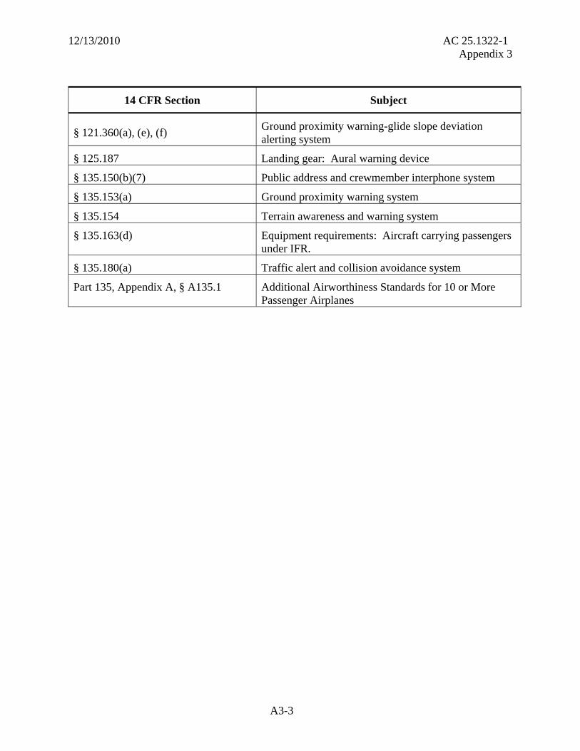
§ 121.360(a), (e), (f) Ground proximity warning-glide slope deviation alerting system
§ 125.187 Landing gear: Aural warning device
§ 135.150(b)(7) Public address and crewmember interphone system
§ 135.153(a) Ground proximity warning system
§ 135.154 Terrain awareness and warning system
§ 135.163(d) Equipment requirements: Aircraft carrying passengers under IFR.
§ 135.180(a) Traffic alert and collision avoidance system
Part 135, Appendix A, § A135.1 Additional Airworthiness Standards for 10 or More Passenger Airplanes

12/13/2010 AC 25.1322-1 Appendix 4
Appendix 4
Related Documents
1. FAA Reports. A paper copy of the following reports may be ordered from the National Technical Information Service, 5285 Port Royal Road, Springfield, VA 22161.
a. Report DOT/FAA/RD-81/38, II, “Aircraft Alerting Systems Standardization Study,
Volume II, Aircraft Alerting Systems Design Guidelines.” b. Report DOT/FAA/CT-96/1, GAMA Report No. 10, “Recommended Guidelines for Part
23 Cockpit/Flight Deck Design” (September 2000), Section 4, Definitions, Primary Field of View.
2. ACs. An electronic copy of the following ACs can be downloaded from the Internet at http://rgl.faa.gov. A paper copy may be ordered from the U.S. Department of Transportation, Subsequent Distribution Office, M-30, Ardmore East Business Center, 3341 Q 75th Avenue, Landover, MD 20795.
Number Title
AC 20-69 Conspicuity of Aircraft Malfunction Indicators
AC 20-88A Guidelines on the Marking of Aircraft Powerplant Instruments (Displays)
AC 25-7A, Change 1 Flight Test Guide for Certification of Transport Category Airplanes
AC 25-11A Electronic Flight Deck Displays
AC 25-23 Airworthiness Criteria for the Installation Approval of a Terrain Awareness and Warning System (TAWS) for Part 25 Airplanes
AC 25.703-1 Takeoff Configuration Warning Systems
AC 25.783-1A Fuselage Doors and Hatches
AC 25.1309-1A System Design and Analysis
AC 25.1329-1B Approval of Flight Guidance Systems
AC 25.1523-1 Minimum Flightcrew 3. Technical Standard Order (TSO). TSO C-151b, “Terrain Awareness and Warning Systems,” can be downloaded from the Internet at http://rgl.faa.gov.
4. European Aviation Safety Agency (EASA) Documents. Copies of the following documents can be found on the EASA website at http://www.EASA.europa.eu.
A4-1

12/13/2010 AC 25.1322-1 Appendix 4
Number Title
AMC 25-11 Electronic Display Systems
AMC 25.1302 Installed Systems and Equipment for Use by the Flightcrew
AMC 25.1309 System Design and Analysis
AMC 25.1322 Alerting Systems 5. U.K. Civil Aviation Authority Document. Patterson, R.D. “Guidelines for Auditory Warning Systems on Civil Aircraft.” Civil Aviation Authority paper 82017. London: Civil Aviation Authority, 1982.
6. Other Related Documents.
a. Abbott, K.; Slotte, S.M.; and Stimson, D.K. Federal Aviation Administration Human Factors Team Report: The Interfaces Between Flightcrews and Modern Flight Deck Systems. June 18, 1996. Federal Aviation Administration, Aircraft Certification Service, Transport Airplane Directorate, 1601 Lind Avenue, SW, Renton, WA 98057-3356. http://www.faa.gov/education_research/training/aqp/library/media/interfac.pdf.
b. DOD-CM-400-18-05, Department of Defense User Interface Specifications for the Defense Information Infrastructure, Defense Information Systems Agency, February 1998. E-mail: [email protected]. The Defense Information Systems Agency website is restricted to visitors from .gov and .mil domains.
c. Edworthy, J. and Adams. A. Warning Design: A Research Perspective. London: Taylor and Francis, 1996. Mortimer House, 37-41 Mortimer Street, London, W1T 3JH. http://www.taylorandfrancis.com.
d. Kuchar, J.K. “Methodology for alerting-system performance evaluation.” Journal of Guidance, Control, and Dynamics, 19, pp. 438-444 (1996). AIAA, 1801 Alexander Bell Drive, Suite 500, Reston, VA 20191. http://www.aiaa.org/content.
e. Parasuraman, R. and Riley, V. “Human and Automation: use, misuse, disuse, abuse.” Human Factors: The Journal of the Human Factors and Ergonomics Society, Volume 39, Number 2, June 1997, pp. 230-253. Human Factors and Ergonomics Society, PO Box 1369, Santa Monica, CA 90406-1369. http://hfes.publisher.ingentaconnect.com/.
f. SAE ARP 4033. Pilot-System Integration, August 1, 1995. SAE International, 400 Commonwealth Drive, Warrendale, PA 15096. http://www.sae.org.
A4-2

12/13/2010 AC 25.1322-1 Appendix 4
A4-3
g. Satchell, P. Cockpit Monitoring and Alerting System. Aldershot, England: Ashgate, 1993. Summit House, 170 Finchley Road, London NW3 6BP, England. http://www.ashgate.com.
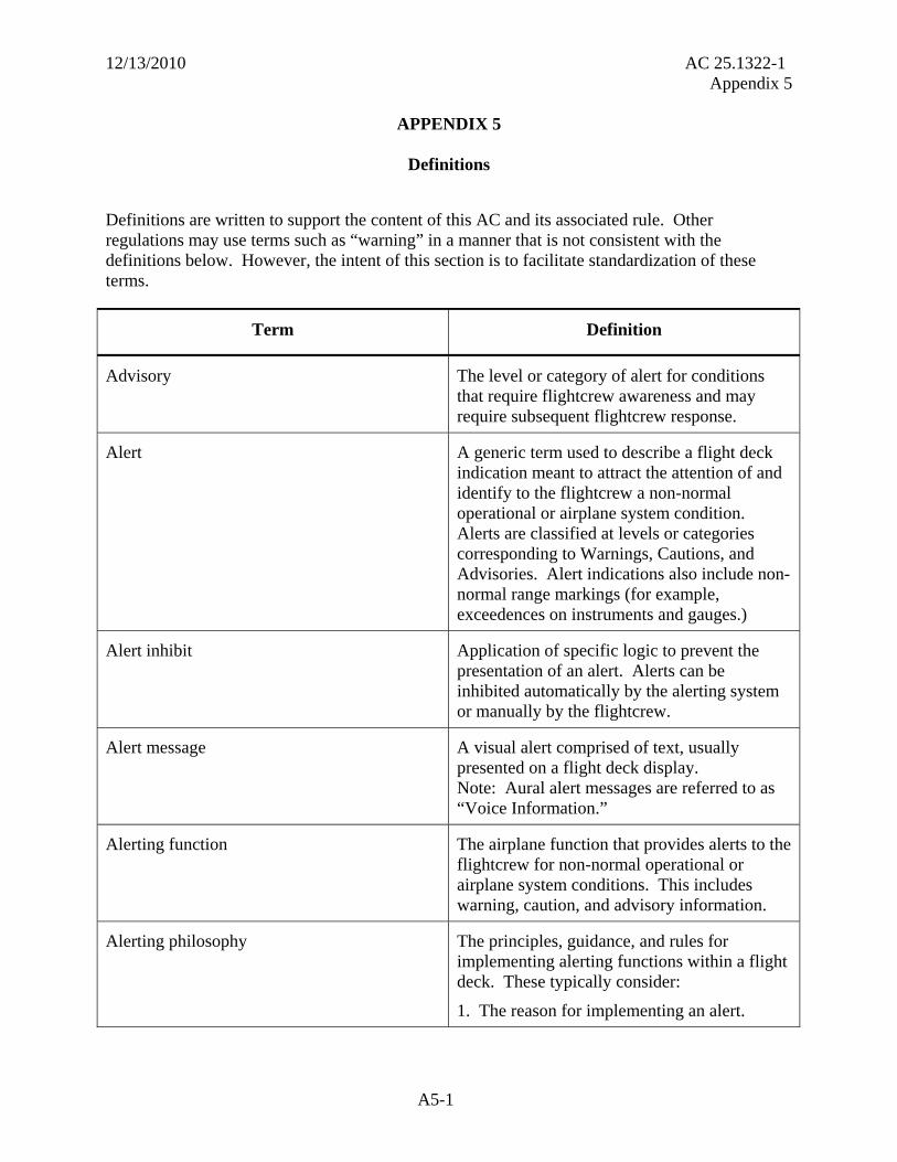
12/13/2010 AC 25.1322-1 Appendix 5
APPENDIX 5
Definitions
Definitions are written to support the content of this AC and its associated rule. Other regulations may use terms such as “warning” in a manner that is not consistent with the definitions below. However, the intent of this section is to facilitate standardization of these terms.
Term Definition
Advisory The level or category of alert for conditions that require flightcrew awareness and may require subsequent flightcrew response.
Alert A generic term used to describe a flight deck indication meant to attract the attention of and identify to the flightcrew a non-normal operational or airplane system condition. Alerts are classified at levels or categories corresponding to Warnings, Cautions, and Advisories. Alert indications also include non-normal range markings (for example, exceedences on instruments and gauges.)
Alert inhibit Application of specific logic to prevent the presentation of an alert. Alerts can be inhibited automatically by the alerting system or manually by the flightcrew.
Alert message A visual alert comprised of text, usually presented on a flight deck display. Note: Aural alert messages are referred to as “Voice Information.”
Alerting function The airplane function that provides alerts to the flightcrew for non-normal operational or airplane system conditions. This includes warning, caution, and advisory information.
Alerting philosophy The principles, guidance, and rules for implementing alerting functions within a flight deck. These typically consider:
1. The reason for implementing an alert.
A5-1

12/13/2010 AC 25.1322-1 Appendix 5
Term Definition
2. The level of alert required for a given condition.
3. The characteristics of each specific alert.
4. Integration of multiple alerts.
Attention-getting cues Perceptual signals (visual, auditory, or tactile/haptic) designed to attract the flightcrew’s attention in order to obtain the immediate awareness that an alert condition exists.
Caution The level or category of alert for conditions that require immediate flightcrew awareness and a less urgent subsequent flightcrew response than a warning alert.
Collector message An alert message that replaces two or more related alert messages that do not share a common cause or effect. Example: A “DOORS” alert collector message is displayed when more than one entry, cargo, or service access door is open at the same time.
Communication message A type of message whose initiating conditions are caused by incoming communications, primarily data link conditions. Traditionally, this type of message is not a flightcrew alert and does not indicate a non-normal system or operational condition.
(1) Comm High A communication message which requires immediate flightcrew awareness and immediate flightcrew response. Note: At this time there are no communication messages defined that require immediate flightcrew response.
(2) Comm Medium An incoming communication message that requires immediate flightcrew awareness and subsequent flightcrew response.
(3) Comm Low An incoming communication message which requires flightcrew awareness and future flightcrew response.
A5-2

12/13/2010 AC 25.1322-1 Appendix 5
Term Definition
False alert An incorrect or spurious alert caused by a failure of the alerting system including the sensor.
Failure An occurrence that affects the operation of a component, part, or element such that it can no longer function as intended. This includes both loss of function and malfunction.
Failure flag One local visual means of indicating the failure of a displayed parameter.
Flashing Short term flashing symbols (approximately 10 seconds) or flash until acknowledged.
Flightcrew response The activity accomplished due to the presentation of an alert such as an action, decision, prioritization, or search for additional information.
Master aural alert An overall aural indication used to attract the flightcrew’s attention that is specific to an alert urgency level (for example, warning or caution).
Master visual alert An overall visual indication used to attract the flightcrew’s attention that is specific to an alert urgency level (for example, warning or caution).
Normal condition Any fault-free condition typically experienced in normal flight operations. Operations are typically well within the airplane flight envelope and with routine atmospheric and environmental conditions.
Nuisance alert An alert generated by a system that is functioning as designed but which is inappropriate or unnecessary for the particular condition.
A5-3

12/13/2010 AC 25.1322-1 Appendix 5
Term Definition
Primary field of view Primary Field of View is based upon the optimum vertical and horizontal visual fields from the design eye reference point that can be accommodated with eye rotation only. The description below and Figure A5-1 provide an example of how this may apply to head-down displays.
With the normal line-of-sight established at 15 degrees below the horizontal plane, the values for the vertical (relative to normal line-of-sight forward of the aircraft) are +/-15 degrees optimum, with +40 degrees up and -20 degrees down maximum.
For the horizontal visual field (relative to normal line-of-sight forward of the aircraft), the values are +/-15 degrees optimum, and +/-35 degrees maximum.
Figure A5-1. Primary Field of View
A5-4

12/13/2010 AC 25.1322-1 Appendix 5
Term Definition
Status A specific aircraft system condition that is recognized using a visual indication, but does not require an alert and does not require flightcrew response. These types of messages are sometimes used to determine airplane dispatch capability for subsequent flights.
Tactile/haptic information An indication means where the stimulus is via physical touch, force feedback, or vibration (for example, a stick shaker).
Time-critical warning A subset of warning. The most urgent warning level to maintain the immediate safe operation of the airplane. Examples of time-critical warnings are:
Predictive and Reactive Windshear Warnings,
Terrain Awareness Warnings (TAWS),
Airborne Collision Avoidance System (ACAS) II Resolution Advisories,
Overspeed Warnings, and
Low Energy Warnings.
Umbrella message An alert message that is presented in lieu of two or more alert messages that share a common cause. Example: A single Engine Shutdown message in lieu of the multiple messages for electrical generator, generator drive, hydraulic pump and bleed air messages, which would otherwise have been displayed. This is different than a collector message. A collector message replaces two or more related alert messages that do “not share” a common cause or effect.
Unique tone (unique sound) An aural indication that is dedicated to specific alerts (for example, fire bell and overspeed).
A5-5

12/13/2010 AC 25.1322-1 Appendix 5
A5-6
Term Definition
Visual alert information A visual indication that presents the flightcrew with data on the exact nature of the alerting situation. For advisory level alerts it also provides awareness.
Voice information A means for informing the flightcrew of the nature of a specific condition by using spoken words.
Warning The level or category of alert for conditions that require immediate flightcrew awareness and immediate flightcrew response.