advantys ftm devicenet ip67 modular i/o splitter … · advantys ftm devicenet ... behavior for...
TRANSCRIPT
Advantys FTM DeviceNetIP67 Modular I/O Splitter BoxUser guide1606223 02 A04 09/2007

2
3
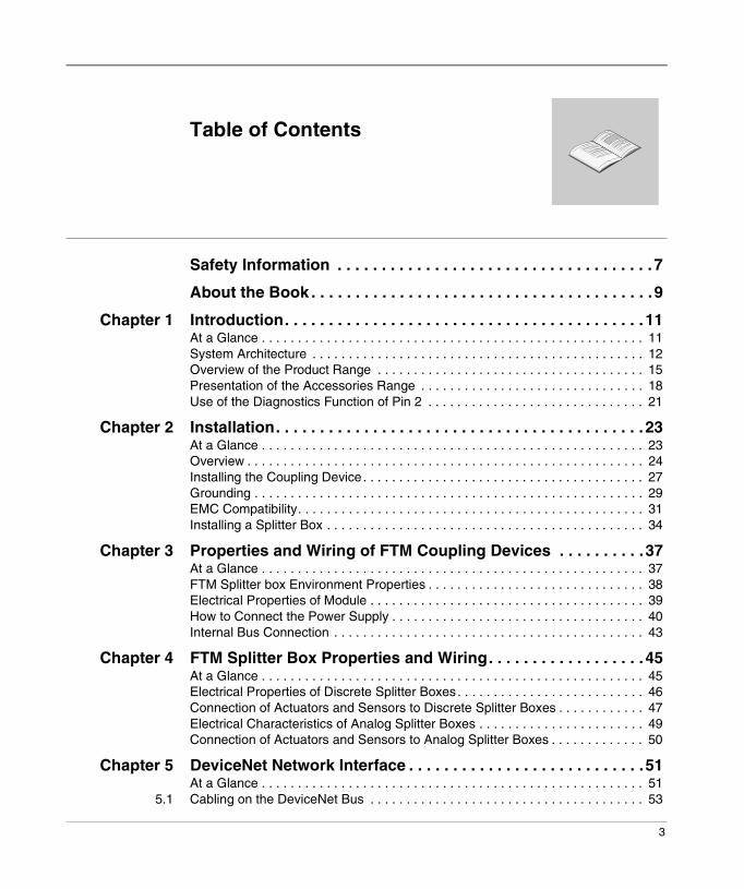
Table of Contents
Safety Information . . . . . . . . . . . . . . . . . . . . . . . . . . . . . . . . . . . . 7
About the Book . . . . . . . . . . . . . . . . . . . . . . . . . . . . . . . . . . . . . . .9
Chapter 1 Introduction. . . . . . . . . . . . . . . . . . . . . . . . . . . . . . . . . . . . . . . . . 11At a Glance . . . . . . . . . . . . . . . . . . . . . . . . . . . . . . . . . . . . . . . . . . . . . . . . . . . . . 11System Architecture . . . . . . . . . . . . . . . . . . . . . . . . . . . . . . . . . . . . . . . . . . . . . . 12Overview of the Product Range . . . . . . . . . . . . . . . . . . . . . . . . . . . . . . . . . . . . . 15Presentation of the Accessories Range . . . . . . . . . . . . . . . . . . . . . . . . . . . . . . . 18Use of the Diagnostics Function of Pin 2 . . . . . . . . . . . . . . . . . . . . . . . . . . . . . . 21
Chapter 2 Installation. . . . . . . . . . . . . . . . . . . . . . . . . . . . . . . . . . . . . . . . . . 23At a Glance . . . . . . . . . . . . . . . . . . . . . . . . . . . . . . . . . . . . . . . . . . . . . . . . . . . . . 23Overview . . . . . . . . . . . . . . . . . . . . . . . . . . . . . . . . . . . . . . . . . . . . . . . . . . . . . . . 24Installing the Coupling Device. . . . . . . . . . . . . . . . . . . . . . . . . . . . . . . . . . . . . . . 27Grounding . . . . . . . . . . . . . . . . . . . . . . . . . . . . . . . . . . . . . . . . . . . . . . . . . . . . . . 29EMC Compatibility. . . . . . . . . . . . . . . . . . . . . . . . . . . . . . . . . . . . . . . . . . . . . . . . 31Installing a Splitter Box . . . . . . . . . . . . . . . . . . . . . . . . . . . . . . . . . . . . . . . . . . . . 34
Chapter 3 Properties and Wiring of FTM Coupling Devices . . . . . . . . . .37At a Glance . . . . . . . . . . . . . . . . . . . . . . . . . . . . . . . . . . . . . . . . . . . . . . . . . . . . . 37FTM Splitter box Environment Properties . . . . . . . . . . . . . . . . . . . . . . . . . . . . . . 38Electrical Properties of Module . . . . . . . . . . . . . . . . . . . . . . . . . . . . . . . . . . . . . . 39How to Connect the Power Supply . . . . . . . . . . . . . . . . . . . . . . . . . . . . . . . . . . . 40Internal Bus Connection . . . . . . . . . . . . . . . . . . . . . . . . . . . . . . . . . . . . . . . . . . . 43
Chapter 4 FTM Splitter Box Properties and Wiring. . . . . . . . . . . . . . . . . . 45At a Glance . . . . . . . . . . . . . . . . . . . . . . . . . . . . . . . . . . . . . . . . . . . . . . . . . . . . . 45Electrical Properties of Discrete Splitter Boxes. . . . . . . . . . . . . . . . . . . . . . . . . . 46Connection of Actuators and Sensors to Discrete Splitter Boxes . . . . . . . . . . . . 47Electrical Characteristics of Analog Splitter Boxes . . . . . . . . . . . . . . . . . . . . . . . 49Connection of Actuators and Sensors to Analog Splitter Boxes . . . . . . . . . . . . . 50
Chapter 5 DeviceNet Network Interface . . . . . . . . . . . . . . . . . . . . . . . . . . .51At a Glance . . . . . . . . . . . . . . . . . . . . . . . . . . . . . . . . . . . . . . . . . . . . . . . . . . . . . 51
5.1 Cabling on the DeviceNet Bus . . . . . . . . . . . . . . . . . . . . . . . . . . . . . . . . . . . . . . 53
4
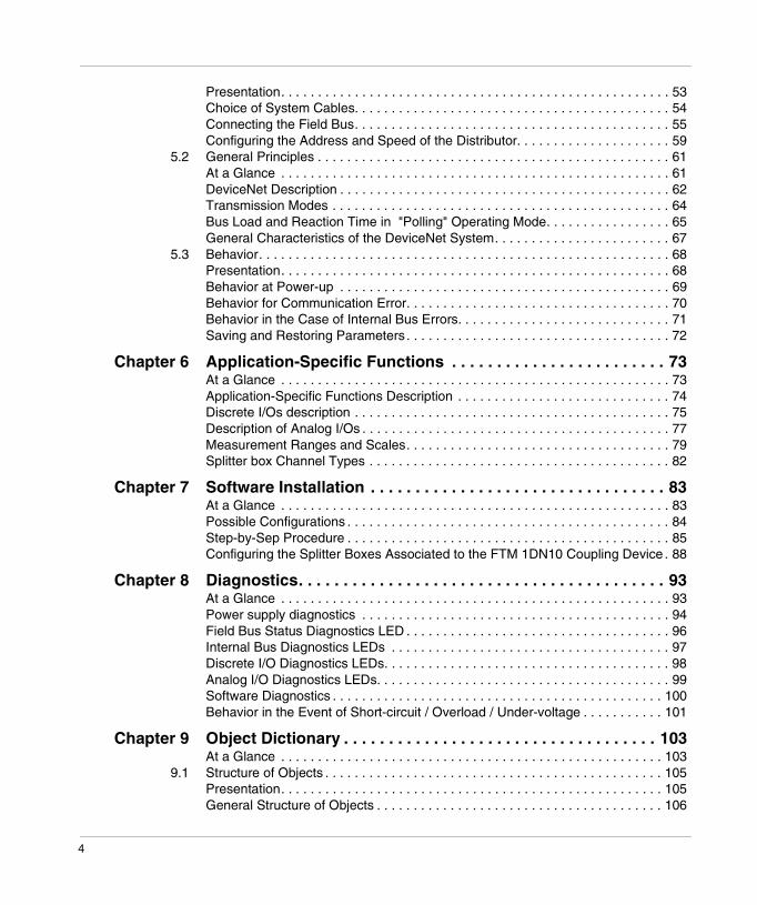
Presentation. . . . . . . . . . . . . . . . . . . . . . . . . . . . . . . . . . . . . . . . . . . . . . . . . . . . . 53Choice of System Cables. . . . . . . . . . . . . . . . . . . . . . . . . . . . . . . . . . . . . . . . . . . 54Connecting the Field Bus. . . . . . . . . . . . . . . . . . . . . . . . . . . . . . . . . . . . . . . . . . . 55Configuring the Address and Speed of the Distributor. . . . . . . . . . . . . . . . . . . . . 59
5.2 General Principles . . . . . . . . . . . . . . . . . . . . . . . . . . . . . . . . . . . . . . . . . . . . . . . . 61At a Glance . . . . . . . . . . . . . . . . . . . . . . . . . . . . . . . . . . . . . . . . . . . . . . . . . . . . . 61DeviceNet Description . . . . . . . . . . . . . . . . . . . . . . . . . . . . . . . . . . . . . . . . . . . . . 62Transmission Modes . . . . . . . . . . . . . . . . . . . . . . . . . . . . . . . . . . . . . . . . . . . . . . 64Bus Load and Reaction Time in "Polling" Operating Mode. . . . . . . . . . . . . . . . . 65General Characteristics of the DeviceNet System. . . . . . . . . . . . . . . . . . . . . . . . 67
5.3 Behavior. . . . . . . . . . . . . . . . . . . . . . . . . . . . . . . . . . . . . . . . . . . . . . . . . . . . . . . . 68Presentation. . . . . . . . . . . . . . . . . . . . . . . . . . . . . . . . . . . . . . . . . . . . . . . . . . . . . 68Behavior at Power-up . . . . . . . . . . . . . . . . . . . . . . . . . . . . . . . . . . . . . . . . . . . . . 69Behavior for Communication Error. . . . . . . . . . . . . . . . . . . . . . . . . . . . . . . . . . . . 70Behavior in the Case of Internal Bus Errors. . . . . . . . . . . . . . . . . . . . . . . . . . . . . 71Saving and Restoring Parameters . . . . . . . . . . . . . . . . . . . . . . . . . . . . . . . . . . . . 72
Chapter 6 Application-Specific Functions . . . . . . . . . . . . . . . . . . . . . . . . 73At a Glance . . . . . . . . . . . . . . . . . . . . . . . . . . . . . . . . . . . . . . . . . . . . . . . . . . . . . 73Application-Specific Functions Description . . . . . . . . . . . . . . . . . . . . . . . . . . . . . 74Discrete I/Os description . . . . . . . . . . . . . . . . . . . . . . . . . . . . . . . . . . . . . . . . . . . 75Description of Analog I/Os . . . . . . . . . . . . . . . . . . . . . . . . . . . . . . . . . . . . . . . . . . 77Measurement Ranges and Scales. . . . . . . . . . . . . . . . . . . . . . . . . . . . . . . . . . . . 79Splitter box Channel Types . . . . . . . . . . . . . . . . . . . . . . . . . . . . . . . . . . . . . . . . . 82
Chapter 7 Software Installation . . . . . . . . . . . . . . . . . . . . . . . . . . . . . . . . . 83At a Glance . . . . . . . . . . . . . . . . . . . . . . . . . . . . . . . . . . . . . . . . . . . . . . . . . . . . . 83Possible Configurations . . . . . . . . . . . . . . . . . . . . . . . . . . . . . . . . . . . . . . . . . . . . 84Step-by-Sep Procedure . . . . . . . . . . . . . . . . . . . . . . . . . . . . . . . . . . . . . . . . . . . . 85Configuring the Splitter Boxes Associated to the FTM 1DN10 Coupling Device . 88
Chapter 8 Diagnostics. . . . . . . . . . . . . . . . . . . . . . . . . . . . . . . . . . . . . . . . . 93At a Glance . . . . . . . . . . . . . . . . . . . . . . . . . . . . . . . . . . . . . . . . . . . . . . . . . . . . . 93Power supply diagnostics . . . . . . . . . . . . . . . . . . . . . . . . . . . . . . . . . . . . . . . . . . 94Field Bus Status Diagnostics LED . . . . . . . . . . . . . . . . . . . . . . . . . . . . . . . . . . . . 96Internal Bus Diagnostics LEDs . . . . . . . . . . . . . . . . . . . . . . . . . . . . . . . . . . . . . . 97Discrete I/O Diagnostics LEDs. . . . . . . . . . . . . . . . . . . . . . . . . . . . . . . . . . . . . . . 98Analog I/O Diagnostics LEDs. . . . . . . . . . . . . . . . . . . . . . . . . . . . . . . . . . . . . . . . 99Software Diagnostics . . . . . . . . . . . . . . . . . . . . . . . . . . . . . . . . . . . . . . . . . . . . . 100Behavior in the Event of Short-circuit / Overload / Under-voltage . . . . . . . . . . . 101
Chapter 9 Object Dictionary . . . . . . . . . . . . . . . . . . . . . . . . . . . . . . . . . . . 103At a Glance . . . . . . . . . . . . . . . . . . . . . . . . . . . . . . . . . . . . . . . . . . . . . . . . . . . . 103
9.1 Structure of Objects . . . . . . . . . . . . . . . . . . . . . . . . . . . . . . . . . . . . . . . . . . . . . . 105Presentation. . . . . . . . . . . . . . . . . . . . . . . . . . . . . . . . . . . . . . . . . . . . . . . . . . . . 105General Structure of Objects . . . . . . . . . . . . . . . . . . . . . . . . . . . . . . . . . . . . . . . 106

5
Class Summary. . . . . . . . . . . . . . . . . . . . . . . . . . . . . . . . . . . . . . . . . . . . . . . . . 1079.2 Class 1H, Identity object . . . . . . . . . . . . . . . . . . . . . . . . . . . . . . . . . . . . . . . . . . 108
Description . . . . . . . . . . . . . . . . . . . . . . . . . . . . . . . . . . . . . . . . . . . . . . . . . . . . 108Class 1H: Instance 0H. . . . . . . . . . . . . . . . . . . . . . . . . . . . . . . . . . . . . . . . . . . . 109Class 1H: Instance 1H. . . . . . . . . . . . . . . . . . . . . . . . . . . . . . . . . . . . . . . . . . . . 109
9.3 Class 2H, Message Router Object . . . . . . . . . . . . . . . . . . . . . . . . . . . . . . . . . . 110Attributes and Available Services . . . . . . . . . . . . . . . . . . . . . . . . . . . . . . . . . . . 110
9.4 Class 3H, DeviceNet Object . . . . . . . . . . . . . . . . . . . . . . . . . . . . . . . . . . . . . . . 111At a Glance . . . . . . . . . . . . . . . . . . . . . . . . . . . . . . . . . . . . . . . . . . . . . . . . . . . . 111Class 3H: Instance 0H. . . . . . . . . . . . . . . . . . . . . . . . . . . . . . . . . . . . . . . . . . . . 112Class 3H: Instance 1H. . . . . . . . . . . . . . . . . . . . . . . . . . . . . . . . . . . . . . . . . . . . 112
9.5 Class 4H: Assembly Object. . . . . . . . . . . . . . . . . . . . . . . . . . . . . . . . . . . . . . . . 113At a Glance . . . . . . . . . . . . . . . . . . . . . . . . . . . . . . . . . . . . . . . . . . . . . . . . . . . . 113Class 4H: Instance 0H. . . . . . . . . . . . . . . . . . . . . . . . . . . . . . . . . . . . . . . . . . . . 114Class 4H: Instance 64H. . . . . . . . . . . . . . . . . . . . . . . . . . . . . . . . . . . . . . . . . . . 115Class 4H: Instance 65H. . . . . . . . . . . . . . . . . . . . . . . . . . . . . . . . . . . . . . . . . . . 116
9.6 Class 5H, Connection Object . . . . . . . . . . . . . . . . . . . . . . . . . . . . . . . . . . . . . . 117At a Glance . . . . . . . . . . . . . . . . . . . . . . . . . . . . . . . . . . . . . . . . . . . . . . . . . . . . 117Class 5: Instance 0H . . . . . . . . . . . . . . . . . . . . . . . . . . . . . . . . . . . . . . . . . . . . . 118Class 5: Instances 1H to 4H . . . . . . . . . . . . . . . . . . . . . . . . . . . . . . . . . . . . . . . 119
9.7 Class 2BH, Acknowledge handler Object . . . . . . . . . . . . . . . . . . . . . . . . . . . . . 120At a Glance . . . . . . . . . . . . . . . . . . . . . . . . . . . . . . . . . . . . . . . . . . . . . . . . . . . . 120Class 2BH: Instance 0H . . . . . . . . . . . . . . . . . . . . . . . . . . . . . . . . . . . . . . . . . . 121Class 2BH: Instance 1H . . . . . . . . . . . . . . . . . . . . . . . . . . . . . . . . . . . . . . . . . . 121
9.8 Class 64H, Coupling Device Configuration . . . . . . . . . . . . . . . . . . . . . . . . . . . . 122Presentation . . . . . . . . . . . . . . . . . . . . . . . . . . . . . . . . . . . . . . . . . . . . . . . . . . . 122Class 64H: Instance 0H. . . . . . . . . . . . . . . . . . . . . . . . . . . . . . . . . . . . . . . . . . . 123Class 64H: Instance 1H. . . . . . . . . . . . . . . . . . . . . . . . . . . . . . . . . . . . . . . . . . . 123
9.9 Class 65H, Splitter Boxes . . . . . . . . . . . . . . . . . . . . . . . . . . . . . . . . . . . . . . . . . 125Presentation . . . . . . . . . . . . . . . . . . . . . . . . . . . . . . . . . . . . . . . . . . . . . . . . . . . 125Class 65H: Instance 0H. . . . . . . . . . . . . . . . . . . . . . . . . . . . . . . . . . . . . . . . . . . 126Class 65H: Instance 1H and the Following Instances. . . . . . . . . . . . . . . . . . . . 126Class 65H: 1H and Following Instances, Attributes 3H to 27H . . . . . . . . . . . . . 127Class 65H: 1H and Following Instances, Attributes 28H to 4F of Discrete Splitter Boxes . . . . . . . . . . . . . . . . . . . . . . . . . . . . . . . . . . . . . . . . . . . . . . . . . . 130Class 65H: 1H and Following Instances, Attributes 28H to 33H for Analog Splitter Boxes . . . . . . . . . . . . . . . . . . . . . . . . . . . . . . . . . . . . . . . . . . . . . . . . . . 131Class 65H: 1H and Following Instances, Attributes 50H to 64H . . . . . . . . . . . . 134
Glossary . . . . . . . . . . . . . . . . . . . . . . . . . . . . . . . . . . . . . . . . . . . . . 139
Index . . . . . . . . . . . . . . . . . . . . . . . . . . . . . . . . . . . . . . . . . . . . . 145

6

1606223 02 A04 09/2007 7
§Safety Information
Important Information
NOTICE Read these instructions carefully, and look at the equipment to become familiar with the device before trying to install, operate, or maintain it. The following special messages may appear throughout this documentation or on the equipment to warn of potential hazards or to call attention to information that clarifies or simplifies a procedure.
The addition of this symbol to a Danger or Warning safety label indicatesthat an electrical hazard exists, which will result in personal injury if theinstructions are not followed.
This is the safety alert symbol. It is used to alert you to potential personalinjury hazards. Obey all safety messages that follow this symbol to avoidpossible injury or death.
DANGER indicates an imminently hazardous situation, which, if not avoided, will result in death or serious injury.
DANGER
WARNING indicates a potentially hazardous situation, which, if not avoided, can result in death, serious injury, or equipment damage.
WARNING
CAUTION indicates a potentially hazardous situation, which, if not avoided, can result in injury or equipment damage.
CAUTION

Safety Information
8 1606223 02 A04 09/2007
PLEASE NOTE Electrical equipment should be installed, operated, serviced, and maintained only by qualified personnel. No responsibility is assumed by Schneider Electric for any consequences arising out of the use of this material.
© 2007 Schneider Electric. All Rights Reserved.

1606223 02 A04 09/2007 9
About the Book
At a Glance
Document Scope This user guide contains the information required to install an IP67 modular I/O splitter box.
It has been designed to help system installers become rapidly familiar with the system, while optimizing the system's features with the most advanced technology available.
Installing the splitter box requires prior knowledge of the relevant communication protocol and should only be carried out by qualified personnel. Special points and warnings regarding safety are highlighted in the different chapters.
The early chapters provide information for designers and installers on installing the mechanical and electrical elements of the system. It details characteristics which are common to the whole Advantys FTM range and is not dependent on the selected communication protocol.
The following chapters, from the section on "Network interface", are specific to the communication protocol. They contain information on specific wiring for the network interface and all the necessary information for the software application programmer, and for the end user (diagnostics).
About the Book
10 1606223 02 A04 09/2007
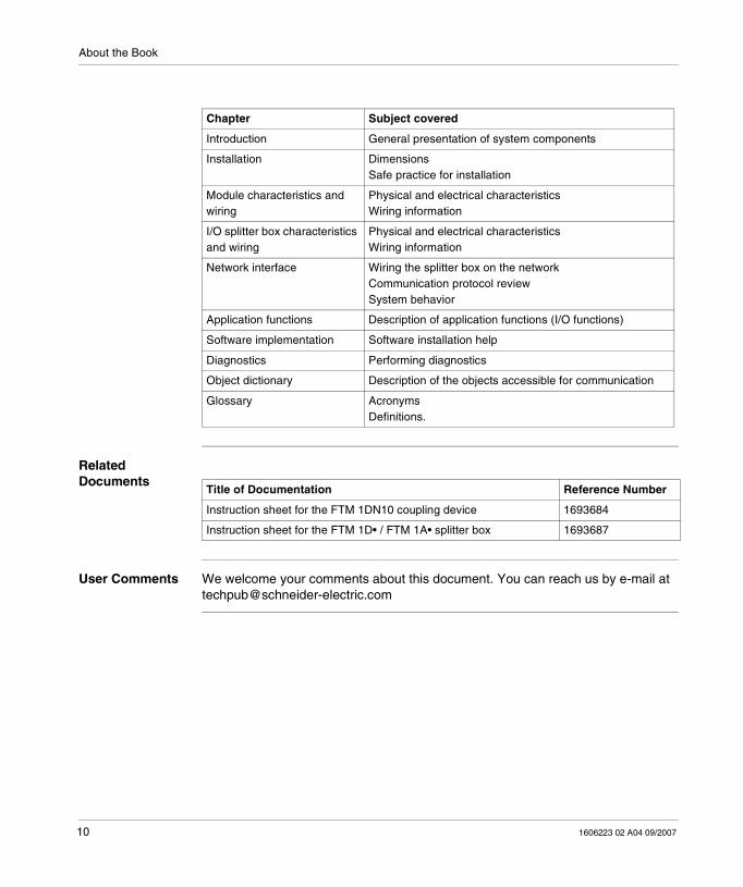
Related Documents
User Comments We welcome your comments about this document. You can reach us by e-mail at [email protected]
Chapter Subject covered
Introduction General presentation of system components
Installation DimensionsSafe practice for installation
Module characteristics and wiring
Physical and electrical characteristicsWiring information
I/O splitter box characteristics and wiring
Physical and electrical characteristicsWiring information
Network interface Wiring the splitter box on the networkCommunication protocol reviewSystem behavior
Application functions Description of application functions (I/O functions)
Software implementation Software installation help
Diagnostics Performing diagnostics
Object dictionary Description of the objects accessible for communication
Glossary AcronymsDefinitions.
Title of Documentation Reference Number
Instruction sheet for the FTM 1DN10 coupling device 1693684
Instruction sheet for the FTM 1D• / FTM 1A• splitter box 1693687

1606223 02 A04 09/2007 11
1Introduction
At a Glance
Introduction This chapter provides a general overview of the Advantys FTM DeviceNet range of IP67 modular I/O splitter boxes.
What's in this Chapter?
This chapter contains the following topics:
Note: The information in this manual is primarily intended for users with some practical knowledge of the CAN standard applied to the DeviceNet field bus. DeviceNet equipment installers and users are advised to read the standard documentation before installing or handling any equipment All detailed standard specifications may be found at http://www.odva.org.
Topic Page
System Architecture 12
Overview of the Product Range 15
Presentation of the Accessories Range 18
Use of the Diagnostics Function of Pin 2 21

Introduction
12 1606223 02 A04 09/2007
System Architecture
At a Glance The Advantys FTM modular system enables you to connect a variable number of input/output splitter boxes, using a single communication interface (field bus module).
These splitter boxes are connected to the module using a hybrid cable which includes the internal bus and power supply (internal, sensor and actuator).
The input/output splitter boxes are independent of the field bus type, thus reducing the number of splitter box references. Once installed, the system is ready to begin operation.
Network Topology
The system topology is a star/line architecture.
Each module is fitted with 4 M12-type connectors for connecting the Advantys FTM splitter boxes (star architecture).

Introduction
1606223 02 A04 09/2007 13
Segment Structure
For each communication or node coupling device, up to 4 I/O splitter boxes may be connected in a daisy chain arrangement (line architecture):
WARNINGRISK OF UNINTENDED EQUIPMENT OPERATION A segment length must not exceed 5 m (16.4 ft). Failure to observe this length restriction may cause the internal bus to malfunction.Failure to follow these instructions can result in death, serious injury, or equipment damage.
Segment 1
5 m maximum
16.40 ft maximum
Maximum of 4 I/O splitter boxes
Maximum of 4 I/O splitter boxes
Maximum of 4 I/O splitter boxes
Maximum of 4 I/O splitter boxes
Seg
men
t 0 Seg
men
t 2 Seg
men
t 3

Introduction
14 1606223 02 A04 09/2007
Maximum Discrete I/O Capacity
The system configuration and the number of I/O splitter boxes connected to the module depend on the type of splitter boxes used.
For a given connecting device, the maximum number of Discrete I/O splitter boxes is:
� 4 per segment, or 64 I/O.� 16 for all of the 4 possible segments of the I/O splitter box module, or 256 Discrete
I/O.
Maximum Configuration
The system configuration and the number of splitter boxes connected to the connecting device depend on the type of splitter boxes used.
The maximum configuration by splitter box type is defined in the following table:
Number of analog splitter boxes Number of Discrete splitter boxes
4 4
3 8
2 12
1 15
0 16

Introduction
1606223 02 A04 09/2007 15
Overview of the Product Range
Different Types of Splitter Boxes
Different types of Advantys FTM splitter boxes are available:� Discrete I/O splitter boxes:
� Compact� Extendable
� Analog I/O splitter boxes:� Compact.
Discrete I/O Splitter Boxes
These splitter boxes are available in compact or extendable versions.
Their properties are as follows:� 24 VDC, IEC type 2 inputs,� 24 VDC, 0.5 A transistor outputs.
Input splitter boxes
These are only used for connecting sensors.
The different types of input splitter boxes are as follows:� 8 M8-type connector splitter boxes, for connecting up to 8 sensors.� 4 M12-type connectors allow you to connect up to 8 sensors (4 in the case of
sensors fitted with a diagnostics function).� 8 M12-type connectors allow you to connect up to 16 sensors (8 in the case of
sensors fitted with a diagnostics function).
Configurable Input/output splitter boxes
These are used for connecting sensors and/or actuators.
The different types of input/output splitter boxes are as follows:� 8 M8-type connector splitter boxes, for connecting up to 8 sensors or actuators.� 4 M12-type connectors allow you to connect up to 8 sensors or actuators (4 in the
case of sensors or actuators fitted with a diagnostics function).� 8 M12-type connectors allow you to connect up to 16 sensors or actuators (8 in
the case of sensors or actuators fitted with a diagnostics function).
Note: Each channel can be configured as an input or output, or as a diagnostics input (pin 2). Standard diagnostics channels conform to the DESINA standard.

Introduction
16 1606223 02 A04 09/2007
Analog I/O Splitter Boxes
These splitter boxes are only available in compact version.
They are used to connect analog sensors or actuators to an M12-type connector:
� 4-input analog splitter boxes (voltage or current),� Analog 4-output splitter boxes (voltage or current).
Compact Splitter Boxes
A compact splitter box does not allow continuity from the internal bus to other splitter boxes on the same segment.
They are used in the following cases:� 1 single splitter box on a segment (no daisy-chaining),� Final splitter box on a segment.
Extendable Splitter Boxes
A splitter box allows continuity from the internal bus to other splitter boxes (daisy-chaining).
WARNINGRISK OF MALFUNCTIONIf an extendable splitter box is used as the final splitter box for an internal bus segment, install a line terminator on the output bus connector.Failure to follow these instructions can result in death, serious injury, or equipment damage.
WARNINGRISK OF NON-COMPLIANCE WITH IP67For IP67 protection:� properly fit all connectors with cables or sealing plugs and tighten,� install cover onto coupling device and tighten captive screws to specified
torque.
Failure to follow these instructions can result in death, serious injury, or equipment damage.

Introduction
1606223 02 A04 09/2007 17
Splitter Box References
The references for discrete splitter boxes are listed in the following table:
The references for analog splitter boxes are listed in the following table:
Reference Connector Discrete input
Discrete Output
Compact Extendable Configurable
FTM 1DD08C08 8 M8 0...8 0...8 x - x
FTM 1DD08C12 4 M12 0...8 0...8 x - x
FTM 1DD16C12 8 M12 0...16 0...16 x - x
FTM 1DD08C08E 8 M8 0...8 0...8 - x x
FTM 1DD08C12E 4 M12 0...8 0...8 - x x
FTM 1DD16C12E 8 M12 0...16 0...16 - x x
FTM 1DE08C08 8 M8 8 - x - -
FTM 1DE08C12 4 M12 8 - x - -
FTM 1DE16C12 8 M12 16 - x - -
FTM 1DE08C08E 8 M8 8 - - x -
FTM 1DE08C12E 4 M12 8 - - x -
FTM 1DE16C12E 8 M12 16 - - x -
Reference Connector Analog Input Analog output Compact Extendable
Voltage Current Voltage Current
FTM 1AE04C12C 4 M12 - 4 - - x -
FTM 1AE04C12T 4 M12 4 - - - x -
FTM 1AS04C12C 4 M12 - - - 4 x -
FTM 1AS04C12T 4 M12 - - 4 - x -

Introduction
18 1606223 02 A04 09/2007
Presentation of the Accessories Range
Connection Cables from the Bus to the Module
Different cables can be used to connect the module to the field bus. These are available in different lengths.
23
8
9
8
FTM 1D 08C08E
FTM 1D 08C12E
FTM 1D 16C12E
FTM 1DE16C12
FTM 1DN10 FTM 1DN10
FTM 1D 08C08
FTM 1D 08C12FTM 1A 04C12
FTM 1DD16C12
+ 24 V
24 V
145 6
11
10
12
12
13
7
13 8
11

Introduction
1606223 02 A04 09/2007 19
Element Reference Function
1 FTX CN3203FTX CN3206FTX CN3210FTX CN3220FTX CN3230FTX CN3250
Cables fitted with 2 M12-type 5 pin elbow connectors, with two ends for connecting the bus to two modules.Available lengths: 0.3 m, 0.6 m, 1 m, 2 m, 3 m and 5 m (0.98 ft, 1.97 ft, 3.28 ft, 6.56 ft, 9.84 ft, 16.4 ft).
2 FTX DP2206FTX DP2210FTX DP2220FTX DP2250
Cables fitted with 2 7/8 type 5 pin connectors, at both ends for daisy-chaining 24 VDC supplies to two coupling devices.Available lengths: 0.6 m, 1 m, 2 m and 5 m (1.97 ft, 3.28 ft, 6.56 ft, 16.4 ft).
3 FTX DP2115FTX DP2130FTX DP2150
Cables fitted with 1 7/8-type 5 pin connector, with one free end and the other for connecting 24 VDC supplies.Available lengths: 1.5 m, 3 m and 5 m (4.92 ft, 9.84 ft, 16.4 ft).
4 FTX CN12M5 Male M12 5-pin connectors for DeviceNet bus cables (encoding A).
FTX CN12F5 Female M12 5-pin connectors for DeviceNet bus cables (encoding A).
5 FTX C78M5 Male and female 7/8-type 5 pin connectors, for 24 VDC supply cables.
FTX C78F5 Female 7/8-type 5 pin connectors, for 24 VDC supply cables.
6 FTX CNCT1 T-connector fitted with 2 7/8-type 5-pin connectors, for supply cables.
7 FTX CNTL12 Line terminators fitted with 1 M12-type connector.
8 FTX CB3203FTX CB3206FTX CB3210FTX CB3220FTX CB3230FTX CB3250
Cables fitted with 2 M12-type elbow connectors, 6 pin connectors, with two ends for connecting the internal bus to the module and splitter box, or for daisy-chaining two splitter boxes.Available lengths: 0.3 m, 0.6 m, 1 m, 2 m, 3 m and 5 m (0.98 ft, 1.97 ft, 3.28 ft, 6.56 ft, 9.84 ft, 16.4 ft).
9 FTX CA3203FTX CA3206FTX CA3210FTX CA3220FTX CA3230FTX CA3250
Cables fitted with 2 M12-type 6 pin connectors, with two ends for connecting 24 VDC supplies to the module and splitter box.
10 FTX CA3103FTX CA3106FTX CA3110FTX CA3120FTX CA3130FTX CA3150
Cables fitted with 1 M12-type 6 pin elbow connector, with one free end for connecting 24 VDC supplies.Available lengths: 0.3 m, 0.6 m, 1 m, 2 m, 3 m and 5 m (0.98 ft, 1.97 ft, 3.28 ft, 6.56 ft, 9.84 ft, 16.4 ft).
11 FTX CY1208 Y-connector for connecting 2 M8-type connectors to an M12 connector.
FTX CY1212 Y-connector for connecting 2 M12-type connectors to an M12 connector.

Introduction
20 1606223 02 A04 09/2007
12 FTX CM08B Sealing plugs for M8-type connectors.
FTX CM12B Sealing plugs for M12-type connectors.
13 FTX CBTL12 Line terminator of the internal bus fitted with 1 M12-type connector.
Element Reference Function

Introduction
1606223 02 A04 09/2007 21
Use of the Diagnostics Function of Pin 2
Diagnostics Function
Advantys FTM splitter boxes enable the use of sensors and actuators fitted with a built-in diagnostics function (conforming to the DESINA standard).
When configured as a diagnostics input, the pin 2 of each M12-type connector can be used to detect external splitter box faults relating to sensors or actuators.
Types of Faults This information is used to detect the following faults:� Damage to the detection surface� Inoperative electronics� No load
Choice of Diagnostics Input
The choice between the sensor input function or diagnostics input function at pin 2 level is made for each channel and each setting, when configuring the splitter box.
Fault Display Faults can be displayed by a red LED on each channel configured as a diagnostics input.
Example 1 Connecting a sensor fitted with a diagnostics function:
1
2
4 (S)
3
Diagnostics
M12 Connector
DESINA sensor

Introduction
22 1606223 02 A04 09/2007
Example 2 Using an FTX DG12 accessory, an M12-type diagnostics adaptor, it is possible to monitor breakages in cables leading to sensors or actuators not fitted with a built-in diagnostics function (only for splitter boxes fitted with M12-type connectors).
Connection of a standard sensor with diagnostics adapter:
1
4 (S)
3
1
2
4 (S)
3
Diagnostics
Sensor
M12 Connector
M12-Adapter FTX DG12(bridging)
1606223 02 A04 09/2007 23
2Installation
At a Glance
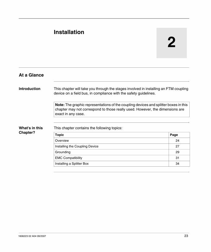
Introduction This chapter will take you through the stages involved in installing an FTM coupling device on a field bus, in compliance with the safety guidelines.
What's in this Chapter?
This chapter contains the following topics:
Note: The graphic representations of the coupling devices and splitter boxes in this chapter may not correspond to those really used. However, the dimensions are exact in any case.
Topic Page
Overview 24
Installing the Coupling Device 27
Grounding 29
EMC Compatibility 31
Installing a Splitter Box 34

Installation
24 1606223 02 A04 09/2007
Overview
Module Description
This is the front view of a coupling device (a coupling device closed on the left, open on the right):
Element Function
1 An M12-type (bus IN) male connector for bus connection.
2 An M12-type (bus OUT) female connector for bus connection.
3 A 7/8-type male connector for connecting the 24 VDC power supplies.
4 Four M12-type female connectors for connecting the I/O splitter boxes via the internal bus.
5 Four segment identification labels.
6 Two module identification labels.
7 Bus address and speed selection switches.
8 and 9 Bus diagnostics LED
10 Sensor supply diagnostics LED.
11 Actuator supply diagnostics and communication status LED.
12 Module functional ground connection.

Installation
1606223 02 A04 09/2007 25
Splitter box Description
Front view of a splitter box:
1 2
6
6
3
5
3 4
5
1
1 2
6
5
3
4
2
5
6
3
1
FTM 1DE16C12
FTM 1DD16C12FTM 1DD16C12EFTM 1DE16C12E
FTM 1D•08C08 FTM 1D•08C12FTM 1A•04C12•
FTM 1D•08C08E FTM 1D•08C12E

Installation
26 1606223 02 A04 09/2007
Element Function
1 An M12-type male connector for connection to the coupling device or previous splitter box.
2 An M12-type female connector for daisy-chaining the internal bus to the next splitter box.
3 Four or eight M12-type female connectors (depending on model) for connecting sensors and actuators.
4 Eight M8-type female connectors for connecting sensors and actuators.
5 One or two splitter box identification labels (depending on model).
6 Four or eight channel identification labels.

Installation
1606223 02 A04 09/2007 27
Installing the Coupling Device
Types of Screws and Tightening Torques
Coupling devices are mounted using two 4 mm (0.15 in.) diameter screws and two washers. The tightening torque is 2 Nm (17.6 lb-in).
Module Dimensions
A coupling device has the following dimensions:
Note: When mounting the unit the support must be flat and smooth so as to prevent any undue stress on the unit which could cause poor sealing.
151
(5.9
5 in
.)
125
±0,5
(4.9
3±0
.02
in.)
20
,5(0
.81
in.) 05
(1.97 in.)
5,43
3,05
22
(1.98 in.)
(0.87 in.)
(1.36 in.)Ø5 (0.19 in.)
Installation
28 1606223 02 A04 09/2007
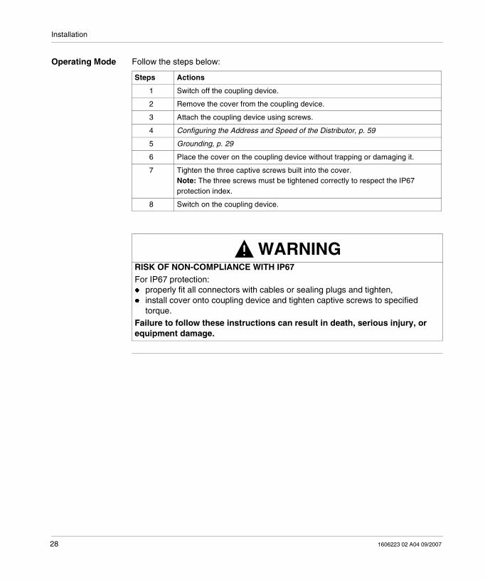
Operating Mode Follow the steps below:
Steps Actions
1 Switch off the coupling device.
2 Remove the cover from the coupling device.
3 Attach the coupling device using screws.
4 Configuring the Address and Speed of the Distributor, p. 59
5 Grounding, p. 29
6 Place the cover on the coupling device without trapping or damaging it.
7 Tighten the three captive screws built into the cover.Note: The three screws must be tightened correctly to respect the IP67 protection index.
8 Switch on the coupling device.
WARNINGRISK OF NON-COMPLIANCE WITH IP67For IP67 protection:� properly fit all connectors with cables or sealing plugs and tighten,� install cover onto coupling device and tighten captive screws to specified
torque.Failure to follow these instructions can result in death, serious injury, or equipment damage.

Installation
1606223 02 A04 09/2007 29
Grounding
Grounding the Coupling Device
The following figure shows the position of the ground electrode on the coupling device.
Method Follow the steps below to connect the ground to the unit:
Note: Use a grounding strip or a conductor with a cross-section of 1 to 1.5mm2 (AWG18, AWG16) and length ≤ 3m (9.84ft). The maximum recommended length for the grounding strip is 3 m (9.84 ft).
EP
44
4
3
2
1
Step Action
1 Remove the cover from the coupling device
2 Crimp the terminal on the ground cable and screw it on the cap.
3 Place the cover on the coupling device
4 Screw the three captive screws built into the cover.

Installation
30 1606223 02 A04 09/2007
Grounding the Splitter Boxes.
The ground connection is connected internally to pin 1 of the M12 connector of the internal bus connector.
If the unit is not grounded properly, it will be sensitive to electromagnetic disturbances. This may lead to unexpected equipment operation.
WARNINGRISK OF IMPROPER GROUNDING
Connect unit to ground using a conductor with cross-section 1...1.5 mm2 (18...16 AWG) and a maximum length of 3 m (9.84 ft). See EMC Compatibility, p. 31.Failure to follow these instructions can result in death, serious injury, or equipment damage.

Installation
1606223 02 A04 09/2007 31
EMC Compatibility
Product Compliance
This product complies with the European directive 89/336/CEE on "electromagnetic compatibility".
The products described in this manual meet all the conditions regarding electromagnetic compatibility and are compliant with the applicable standards. However, this does not mean that the electromagnetic compatibility of your installation is assured.
This is why it is strongly recommended to follow all indications concerning an EMC compliant installation. Only in these conditions and thanks to the exclusive use of CE approved components, will the devices used be deemed as compliant with the EMC directives.
When handling the products, ensure that all safety measures related to electromagnetic compatibility and all conditions for the use of the products are complied with by all persons concerned. This is especially important when handling products sensitive to electrostatic discharges.
The products described in this manual contain highly complex semiconductors that can be damaged or destroyed by electrostatic discharges (ESD). If, for example, they are used within the vicinity of devices rated as class A or B according to IEC 61000-4-4, the level of electromagnetic interference may be enough to cause the device to operate unexpectedly, and/or to damage it.
Damage may not necessarily cause a failure or malfunction that is immediately detectable. It may occur sporadically or in a delayed manner.
WARNINGRISK OF UNINTENDED EQUIPMENT OPERATION
Where there is a risk of electromagnetic interference, the system designer must implement the necessary protective measures.Failure to follow these instructions can result in death, serious injury, or equipment damage.
e

Installation
32 1606223 02 A04 09/2007
Grounding A low impedance connection with a maximum length of 3 m (9.84 ft) must be installed between the splitter box's ground electrode and the reference ground in order to discharge the noise voltages. The inductance of standard grounding cables (PE) presents a risk of high impedance when high frequency noise voltages are present. It is therefore advisable to use grounding strips. If this solution is not possible, use a ground conductor with a large cable cross-section and a ground connection that is as short as possible.
If the unit is not grounded properly, it will be sensitive to electromagnetic disturbances. This may lead to unexpected equipment operation.
Cable Routing Make sure that the following basic wiring rules are followed:
� Keep the data wire and the power cables apart from one another, in so far as is possible.
� Make sure there is a space of at least 10 cm (3.94 in) between the data wires and the power cables.
� The data wires and power cables must only cross at a right angle to one another.� It is advisable to route the data wires and power cables through separate shielded
ducts.� When laying the cables, the noise voltage from other devices or wires must be
considered. This particularly applies to frequency converters, motors and other devices or cables generating high frequency disturbances. High frequency sources and the cables described in this manual must be as far apart from each other as possible.
WARNINGRISK OF IMPROPER GROUNDING
Connect unit to ground using a conductor with cross-section 1...1.5 mm²
(16...18 AWG) and maximum length 3 m (9.84 ft).
Failure to follow these instructions can result in death, serious injury, or equipment damage.
WARNINGRISK OF UNINTENDED EQUIPMENT OPERATIONPlease read and comply with the cabling rules listed above. Failure to comply with these wiring rules is a common cause of EMC problems.Failure to follow these instructions can result in death, serious injury, or equipment damage.

Installation
1606223 02 A04 09/2007 33
Control of Inductive Loads
The outputs of the devices described in this manual are equipped with an integrated protective system against the high noise voltages that may be generated by inductive loads.
Integrated protective system against the high noise voltages generated by inductive loads
The varistor rapidly discharges the energy accumulated in the magnetic field of the inductive load.
The high voltages arising from the disconnection of inductive loads create large fields in the wires that may cause disturbances in nearby circuits or devices. It is advisable to provide an anti-interference device at the load level. In this way, the voltage peak generated by the inductive load is short-circuited directly at the point at which it occurs.
VaristorInductive loade.g. electromagnetic valve

Installation
34 1606223 02 A04 09/2007
Installing a Splitter Box
Types of Screws and Tightening Torques
The splitter boxes are mounted using two 4 mm (0.15 in.) diameter screws and two washers. The tightening torque is 2 Nm (17.6 lb-in).
Dimensions of Extendable Splitter Boxes
The dimensions of the extendable splitter boxes are as follows: FTM 1DD16C12EFTM1DE16C12E
FTM 1D•08C12E
Common view
FTM 1D•08C08E

Installation
1606223 02 A04 09/2007 35
Dimensions of Compact Splitter Boxes
The dimensions of the compact splitter boxes are as follows:
Operating Mode Follow the steps below:
WARNINGRISK OF NON-COMPLIANCE WITH IP67For IP67 protection:� properly fit all connectors with cables or sealing plugs and tighten,� install cover onto coupling device and tighten captive screws to specified
torque.
Failure to follow these instructions can result in death, serious injury, or equipment damage.
FTM 1D•08C12FTM 1A•04C12•
Common viewFTM 1DD16C12FTM1DE16C12 FTM 1D•08C08
Steps Actions
1 Remove the identification labels (see Removing an Identification Label, p. 36).
2 Attach the splitter box to the functional ground.
3 Mount the splitter box using the two screws.
4 Replace the identification labels in the corresponding module slots on the splitter box by pressing lightly.

Installation
36 1606223 02 A04 09/2007
Removing an Identification Label
Follow the steps below:
Steps Actions
1 Insert a screwdriver under the open part of the label.
2 Remove the label by prising it off with the screwdriver.
WARNINGRISK OF NON-COMPLIANCE WITH IP67For IP67 protection:� properly fit all connectors with cables or sealing plugs and tighten,� install cover onto coupling device and tighten captive screws to specified
torque.
Failure to follow these instructions can result in death, serious injury, or equipment damage.

1606223 02 A04 09/2007 37
3Properties and Wiring of FTM Coupling Devices
At a Glance
Introduction This chapter provides an overview of FTM splitter boxes.
What's in this Chapter?
This chapter contains the following topics:
Topic Page
FTM Splitter box Environment Properties 38
Electrical Properties of Module 39
How to Connect the Power Supply 40
Internal Bus Connection 43

Properties and Wiring of FTM Coupling Devices
38 1606223 02 A04 09/2007
FTM Splitter box Environment Properties
Environment Characteristics
Characteristics Description Reference standards
Product certifications cULus -
Operating temperature 0 °C (32 °F)... 55 °C (131 °F)... -
Storage temperature - 25 °C (-13 °F) ... 70 °C (158 °F)... -
Degree of protection IP67 -
Altitude 0 m (0 ft)...2000 m (6561 ft) According to IEC 529
Resistance to vibrations 0.15 mm (0.0059 in) According to IEC 68-2-6, Fc test
Shock resistance 50 gn, duration: 11 ms According to IEC 68-2-27, Fc test
Withstand capacity for electrostatic discharges
� Contact: + 4 kV� Air: + 8kV
According to IEC 61000-4-2
Withstand capacity for radiated fields
10 V/m According to IEC 61000-4-3
Withstand capacity for fast transients
� Power supply: + 2 kV� Signal: + 2 kV
According to IEC 61000-4-4
Withstand capacity for surge
� Power supply (symmetrical and asymmetrical): + 500V
� Signals (symmetrical and asymmetrical): + 1000V� PE: + 500 V
According to IEC 61000-4-5
Withstand capacity for conducted fields
10 VAC rms According to IEC 61000-4-6
Withstand capacity for 50 Hz magnetic fields
30 A/m (9.15 A/ft) According to IEC 61000-4-8
Mounting In all positions -

Properties and Wiring of FTM Coupling Devices
1606223 02 A04 09/2007 39
Electrical Properties of Module
Electrical Characteristics
Characteristic Description
Operating voltage 24 VDC
Bus and I/O under-voltage detection < 18 VDC
Maximum supply current 9 A
Internal current draw 70 mA

Properties and Wiring of FTM Coupling Devices
40 1606223 02 A04 09/2007
How to Connect the Power Supply
Description The power supply is connected using a 5-pin 7/8" connector.
This connector is used to supply power to the following elements:
� Coupling devices� Splitter boxes� Sensors� Actuators
Power Supply for Coupling Devices, Splitter Boxes and Sensors
The splitter boxes require a voltage supply of 24 VDC (class 2).
It must comply with directives applicable to industrial power supplies.
Power Supply for Coupling Device
We advise you to use a switch mode power supply for the coupling device, sensors and actuators.
CAUTIONREVERSE POLARITY AND OVERCURRENT HAZARDS� Do not supply 7/8” connector pins with more than 9A maximum current per pin.� Do not reverse the polarity of the power supplied to the FTM coupling device.Failure to follow these instructions can result in injury or equipment damage.
CAUTIONRISK OF IMPROPER POWER SUPPLYThe coupling device's power must be taken from the sensor power supply.
Failure to follow these instructions can result in injury or equipment damage.

Properties and Wiring of FTM Coupling Devices
1606223 02 A04 09/2007 41
Power Supply Ratings
The rating of the power supplies depends on the number and respective ratings of the connected devices.
Assembling the Power Supply Cable
The following diagram describes the design characteristics and dimensions of the 7/8" power supply cable and the connector cable.
WARNINGRISK OF UNINTENDED EQUIPMENT OPERATION The system voltage must never be less than 18 VDC, regardless of the configuration.Failure to follow these instructions can result in death, serious injury, or equipment damage.
1
32
54
Properties and Wiring of FTM Coupling Devices
42 1606223 02 A04 09/2007
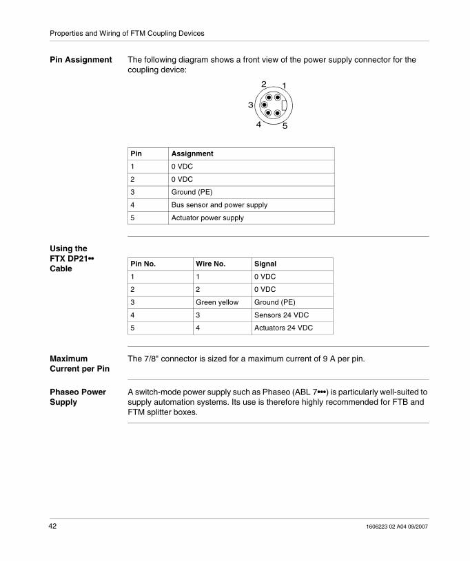
Pin Assignment The following diagram shows a front view of the power supply connector for the coupling device:
Using the FTX DP21•• Cable
Maximum Current per Pin
The 7/8" connector is sized for a maximum current of 9 A per pin.
Phaseo Power Supply
A switch-mode power supply such as Phaseo (ABL 7•••) is particularly well-suited to supply automation systems. Its use is therefore highly recommended for FTB and FTM splitter boxes.
Pin Assignment
1 0 VDC
2 0 VDC
3 Ground (PE)
4 Bus sensor and power supply
5 Actuator power supply
1
5
3
2
4
Pin No. Wire No. Signal
1 1 0 VDC
2 2 0 VDC
3 Green yellow Ground (PE)
4 3 Sensors 24 VDC
5 4 Actuators 24 VDC

Properties and Wiring of FTM Coupling Devices
1606223 02 A04 09/2007 43
Internal Bus Connection
Internal Bus Connection
Internal bus connection fulfils two functions:
� Power supply for I/O FTM splitter boxes.� Communication between the coupling device and the FTM I/O splitter boxes.
The internal bus between the coupling device and the I/O FTM splitter boxes must only be connected using pre-formed cables, available in different lengths (FTX CB32••).
Wiring Diagram
Element Function
1 FTM Coupling Device
2 Coupling box cover
3 FTM splitter box
4 Internal bus cable
5 Incoming bus cable
6 Line terminator
7 Power supply wiring
8 M12 cable to detector or actuator
9 PLC
10 24 VDC Supply
1 910
75
4
2
6
8
3

Properties and Wiring of FTM Coupling Devices
44 1606223 02 A04 09/2007
Operating Mode Using the wiring diagram shown above, follow the steps below:
Notes
Internal Bus Segment Terminator
Each segment of the internal bus must be terminated by a compact splitter box or an extendable splitter box with a line terminator. This line terminator is already built into each of the compact splitter boxes.
The connectors of all unused segments must have a line terminator.
Step Action
1 Connect splitter box 3 to coupling device1 using internal bus cable 4.
2 Connect the M12 or M8 cables for the detectors or actuators to splitter box 3.
3 Connect incoming bus cable 5 to the "Bus In" connection point of cover 2.
4 Connect the outgoing bus cable to the following element or, if coupling device is the last element, connect a line terminator 6.
5 Connect the 24 VDC power supply 10 using the 7/8" connector.
Note: When tightening conductor screws, be careful to apply the recommended tightening torque of 0.5 Nm (4.42 lb-in). Insufficient tightening of the field bus, internal bus, or I/O connections is a common cause of errors or malfunctions.
WARNINGRISK OF UNINTENDED EQUIPMENT OPERATION � Do not exchange I/O modules within an installation.� Identify and clearly mark the internal bus cables and the FTM I/O splitter boxes.� In case of coupling device exchange for maintenance, keep the same network
address.Failure to follow these instructions can result in death, serious injury, or equipment damage.

1606223 02 A04 09/2007 45
4FTM Splitter Box Properties and Wiring
At a Glance
Introduction This chapter provides an overview of all FTM splitter boxes.
What's in this Chapter?
This chapter contains the following topics:
Topic Page
Electrical Properties of Discrete Splitter Boxes 46
Connection of Actuators and Sensors to Discrete Splitter Boxes 47
Electrical Characteristics of Analog Splitter Boxes 49
Connection of Actuators and Sensors to Analog Splitter Boxes 50

FTM Splitter Box Properties and Wiring
46 1606223 02 A04 09/2007
Electrical Properties of Discrete Splitter Boxes
Splitter Box Properties
Input Characteristics
Output characteristics
Properties Description
Splitter box's internal current draw � 30 mA (M8)� 50 mA (M12)
Operating voltage 24 VDC
Maximum power current for the splitter box 4 A
Maximum auxiliary power current (only for FTM 1DD16C12) 4 A
Bus and I/O under-voltage detection < 18 VDC
Characteristic Description
Compliance with IEC 1131-2 Type 2
Compliance with P.D (Potential Difference) 2 wire/3 wire Yes
Rated power voltage 24 VDC
Maximum current 200 mA
Sensor power supply 18...30 VDC
Logic Positive
Filtering input 1 ms
Displaying channel status Yellow LED, 1 LED per input
Reverse polarity protection Yes
Characteristic Description
Output type Transistors
Output voltage 24 VDC
Outgoing current 0.5 A
Response time < 0.5 ms
Maximum switching cycle � Resistive: 50 Hz� Inductive: 5 Hz
Maximum lamp load 10 W
Displaying channel status Yellow LED, 1 LED per input
Connection for outputs / cable lengths� 0.75mm2(AWG 20) / 10 m (32.8 ft) maximum
� 0.34 mm2(AWG 22) / 5 m (16.40 ft) maximum

FTM Splitter Box Properties and Wiring
1606223 02 A04 09/2007 47
Connection of Actuators and Sensors to Discrete Splitter Boxes
Connection Properties
The sensors and actuators can be connected using either pre-formed cables or cables of your own making, provided they comply with the specifications for wires of
cross-section < 0.75 mm2 (AWG 20).
Two sealing plugs are supplied with each splitter box and are available as accessories with the following product references:
� FTX CM12B (packet of 10 M12 sealing plugs).� FTX CM08B (packet of 10 M8 sealing plugs).
Assignment of M12 Connector Pins
The following diagram shows the front view of a 5-pin M12 connector and the convention for numbering the pins:
WARNINGRISK OF NON-COMPLIANCE WITH IP67For IP67 protection:� properly fit all connectors with cables or sealing plugs and tighten,� install cover onto coupling device and tighten captive screws to specified
torque.Failure to follow these instructions can result in death, serious injury, or equipment damage.
Pin Assignment
1 +24 VDC (detector power supply)
2 I/O signal
3 0 VDC (GND)
4 I/O signal
5 Functional ground (PE)
54 3
1 2
FTM Splitter Box Properties and Wiring
48 1606223 02 A04 09/2007
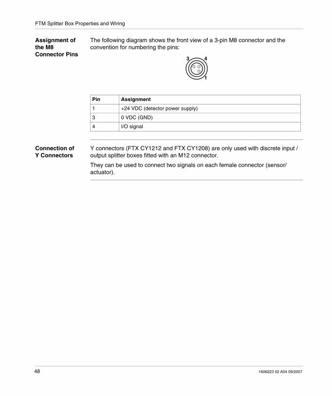
Assignment of the M8 Connector Pins
The following diagram shows the front view of a 3-pin M8 connector and the convention for numbering the pins:
Connection of Y Connectors
Y connectors (FTX CY1212 and FTX CY1208) are only used with discrete input / output splitter boxes fitted with an M12 connector.
They can be used to connect two signals on each female connector (sensor/actuator).
Pin Assignment
1 +24 VDC (detector power supply)
3 0 VDC (GND)
4 I/O signal
43
1

FTM Splitter Box Properties and Wiring
1606223 02 A04 09/2007 49
Electrical Characteristics of Analog Splitter Boxes
Splitter box Characteristics
Input properties
Output characteristics
Characteristic Description
Splitter box's internal current draw 50 mA
Operating voltage 24 VDC
Maximum power current for the splitter box
4 A
Maximum power current per channel � For inputs: < 0.2 A� For outputs: < 1.6 A
Bus and I/O under-voltage detection < 18 VDC
Properties Description of FTM 1AE04C12C Description of FTM 1AE04C12T
Type 300 Ω differential FTM 1AE04C12T: 1 ΜΩ differential
Measurement range � 0...20 mA� 4...20 mA
� +/-10 VDC� 0...10 VDC
Resolution 15 bits 15 bits + sign
Conversion time < 2 ms / channel
Input filter 1 ms
Displaying channel status By LED
Connection for inputs / cable lengths 30 m (98.42 ft) maximum
Properties Description of FTM 1AS04C12C Description of FTM 1AS04C12T
Type 300 Ω Differential 1 MΩdifferential
Measurement range � 0...20 mA� 4...20 mA
� +/-10 VDC� 0...10 VDC
Resolution 11 bits 11 bits + sign
Conversion time < 1 ms / channel
Displaying channel status By LED
Connection for outputs / cable lengths 30 m (98.42 ft) maximum

FTM Splitter Box Properties and Wiring
50 1606223 02 A04 09/2007
Connection of Actuators and Sensors to Analog Splitter Boxes
Connection Properties
The sensors and actuators can be connected using either pre-formed cables or cables of your own making, provided they comply with the specifications for wires of
cross-section < 0.75 mm2 (AWG 20).
The shielding is provided by the metal thread of the female M12 connector For this reason, we recommend that you only use female M12 connectors with metal threads The shielding must be connected to connector's metal sleeve.
Two sealing plugs are supplied with each splitter box and are available as accessories with the following product references:
� FTX CM12B (packet of 10 M12 sealing plugs).� FTX CM08B (packet of 10 M8 sealing plugs).
Assignment of M12 Connector Pins
The following diagram shows the front view of a 5-pin M12 connector and the convention for numbering the pins:
WARNINGRISK OF NON-COMPLIANCE WITH IP67For IP67 protection:� properly fit all connectors with cables or sealing plugs and tighten,� install cover onto coupling device and tighten captive screws to specified
torque.Failure to follow these instructions can result in death, serious injury, or equipment damage.
Pin Analog IN assignment Analog OUT assignment
1 +24 VDC (detector power supply) +24 VDC (detector power supply)
2 Analog input + Not used
3 0 VDC (GND) 0 VDC (GND)
4 Analog input - Analog output
5 Not used Not used
54 3
1 2

1606223 02 A04 09/2007 51
5DeviceNet Network Interface
At a Glance
Description This chapter provides theoretical elements for DeviceNet operations.
What's in this Chapter?
This chapter contains the following sections:
Section Topic Page
5.1 Cabling on the DeviceNet Bus 53
5.2 General Principles 61
5.3 Behavior 68

DeviceNet Network Interface
52 1606223 02 A04 09/2007

DeviceNet Network Interface
1606223 02 A04 09/2007 53
5.1 Cabling on the DeviceNet Bus
Presentation
Introduction The following section describes the elements required for wiring the Advantys FTM coupling devices and splitter boxes to the DeviceNet bus.
What's in this Section?
This section contains the following topics:
Topic Page
Choice of System Cables 54
Connecting the Field Bus 55
Configuring the Address and Speed of the Distributor 59

DeviceNet Network Interface
54 1606223 02 A04 09/2007
Choice of System Cables
The Different Cables
Depending on the requirements of the different applications, the system wiring at the field bus end can be performed using:
� a round cable,� a flat grey cable specific to the DeviceNet system.
Two electrical criteria are important when choosing a suitable transmission cable:
� Ohmic resistance (cable section), due to the auxiliary power supply� Transmission characteristics: Impedance of 121 Ohms (1/4, 1/2W or more)
Structure of Cable Systems for DeviceNet
The various cables always comprise 4 wires. The transmission technique means that the cables must be shielded
An additional auxiliary power supply is needed for the actuators.
Diagrams 3-4 (DN round cable) and 3-5 (DN profile line) show the composition of the cables.
The maximum admissible current for the cable system (DeviceNet and ODVA specification, chapter 10) is 9 A!
Consequently, all other devices (e.g. 7/8" connector) are sized for a maximum current of 9 A!

DeviceNet Network Interface
1606223 02 A04 09/2007 55
Connecting the Field Bus
Description The splitter box can either be in the middle of the chain connection or at line end.
The field bus is connected via a 5-pin M12 connector.
Illustration of a Mini-style M12 Connector
The following diagram shows the characteristics of the chaining cable connector:
Bus Connector Pin Assignment.
The BUS IN connector is a 5-pin M12 male connector.
The BUS OUT connector is a 5-pin M12 female connector.
The following diagram shows a front view of the bus connectors:
The following table gives the assignments of the bus connector pins:
Pin Signal Meaning
1 Shielding Bus shielding
2 V+ 24 VDC power supply for coupling device
3 V- 0 VDC power supply for coupling device
4 CAN_H CAN_High bus line
5 CAN_L CAN_Low bus line
Note: Pin 1 is connected to the splitter box ground terminal.
WARNINGRISK OF NON-COMPLIANCE WITH IP67For IP67 protection:� properly fit all connectors with cables or sealing plugs and tighten,� install cover onto coupling device and tighten captive screws to specified
torque.
Failure to follow these instructions can result in death, serious injury, or equipment damage.
32
1 4
5
BUSOUT
3 2
14
5
BUSIN

DeviceNet Network Interface
56 1606223 02 A04 09/2007
Illustration of an Open-style Connector
The following diagram shows an Open-style connector with the wire assignment:
Element Function Wire color
1 V- Black
2 CAN_L Blue
3 Shielding Shielding
4 CAN_H White
5 V+ Red

DeviceNet Network Interface
1606223 02 A04 09/2007 57
System Wiring Depending on the requirements of the different applications, the system wiring at the field bus end can be performed using a round cable.
Schneider Electric offers a wide range of pre-manufactured and round cables.
The various cables always comprise 4 wires. The transmission technique means that the cables must be shielded
The following diagram shows the composition of the cable.
Note: Two electrical criteria are important when choosing a suitable transmission cable:� transmission characteristics� impedance of 121Ω (1/4, 1/2 W or more).
Element Function
1 Cable sheath
2 Shielding strip
3 CAN_H (white)
4 CAN_L (blue)
5 V+ wire (red)
6 V- wire (black)
DeviceNet Network Interface
58 1606223 02 A04 09/2007
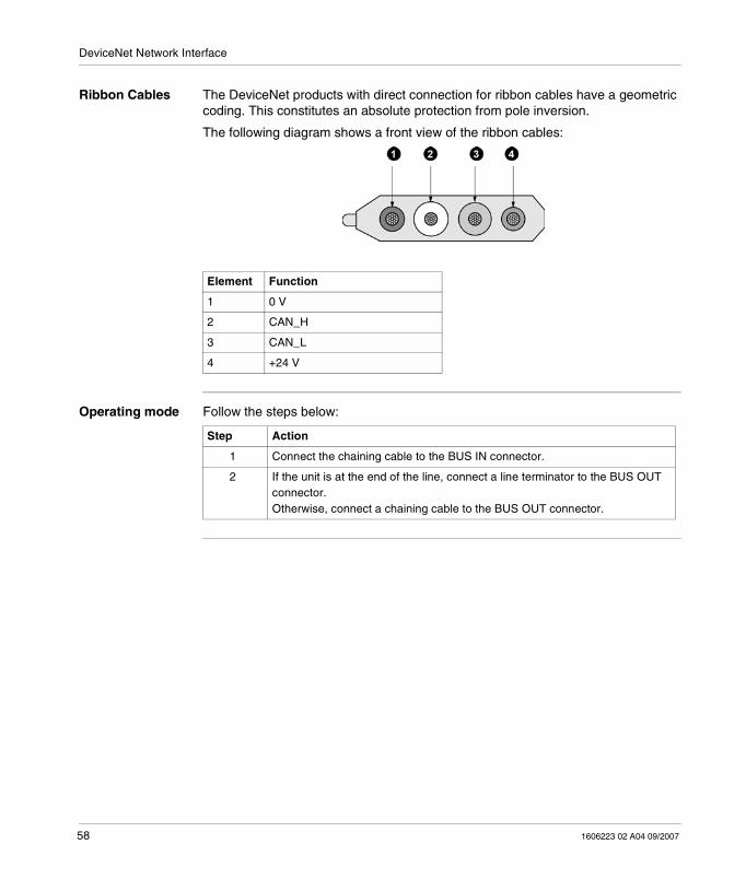
Ribbon Cables The DeviceNet products with direct connection for ribbon cables have a geometric coding. This constitutes an absolute protection from pole inversion.
The following diagram shows a front view of the ribbon cables:
Operating mode Follow the steps below:
Element Function
1 0 V
2 CAN_H
3 CAN_L
4 +24 V
Step Action
1 Connect the chaining cable to the BUS IN connector.
2 If the unit is at the end of the line, connect a line terminator to the BUS OUT connector.Otherwise, connect a chaining cable to the BUS OUT connector.

DeviceNet Network Interface
1606223 02 A04 09/2007 59
Configuring the Address and Speed of the Distributor
Operating mode Follow the steps below:
Rotary Switches - Illustration
Step Action
1 Switch off the coupling device.
2 Unscrew the three screws on the cover.
3 Set the communication speed.
4 Set the splitter box address.
5 Screw the cover back on.
Element Function
1 Transmission speed selector switch
2 Selector switch Node-ID x 10
3 Selector switch Node-ID x 1
0 123
45
6
8
9
7
0 123
4
5
68
9
7
0 123
45
68
9
7
1
32
X10 X1
Speed

DeviceNet Network Interface
60 1606223 02 A04 09/2007
Assignment of the Address on the Network
The address is configured using two specially designed rotary switches. Addresses can be configured from 1 to 99. Address 0 cannot be used.
Adjustment of the Transmission Speed
The transmission speed is configured using a rotary switch.
The following transmission speeds are possible:
Note: When assigning the addresses, ensure that each node is assigned to a single specific address.A configured address is registered at power up. It cannot be changed if you do not remove the cover.
Switch position Transmission Speed
0, 3, 4, 5, 6, 7, 8, 9. 125 Kbits/s
1 250 Kbits/s
2 500 Kbits/s
Note: When adjusting the transmission speed, ensure that each network element is set to the same speed.The configured transmission speed is registered at power-up. It cannot be changed without removing the cover.

DeviceNet Network Interface
1606223 02 A04 09/2007 61
5.2 General Principles
At a Glance
Introduction This section addresses the general principles for operating and using the DeviceNet field bus.
What's in this Section?
This section contains the following topics:
Topic Page
DeviceNet Description 62
Transmission Modes 64
Bus Load and Reaction Time in "Polling" Operating Mode 65
General Characteristics of the DeviceNet System 67

DeviceNet Network Interface
62 1606223 02 A04 09/2007
DeviceNet Description
Type of Network DeviceNet is a Low-End open network that enables the direct connection between simple industrial devices such as detectors and power break switches (actuators), as well as more sophisticated devices such as barcode readers and frequency converters with control systems (PLCs).
DeviceNet Product Certification
The DeviceNet systems is based on the widely used CAN (Controller Area Network) technology - OSI layers 1 and 2 – and in compliance with international standards EN50325 and IEC62026. It uses standard chips that are also used in various industrial applications throughout the world, for example in the automotive industry.
Below are two DeviceNet logos but only one of them is certified.
Network Heat Resistance
Due to its robust protocol, DeviceNet differs from other systems through its excellent resistance to high temperatures and interference fields. Moreover, it displays exceptionally resistant network operation.
Adaptability The DeviceNet (CAN) system is suited to the industrial automation requirements.
Implementation Time
The Plug&Play connection technique and the network cable power supply (potentially with the auxiliary power supply cable) reduces the time needed for implementation and maintenance.
Note: The uncertified DeviceNet logo is very similar to the certified one.Only products with the following logo are DeviceNet certified.DeviceNet certified logo:
Certified logo Uncertified logo

DeviceNet Network Interface
1606223 02 A04 09/2007 63
DeviceNet Application Layer
The DeviceNet system application layer uses the 'Producer-Consumer' process thus enabling very efficient data transfer. Unlike the conventional "Source-Target" model, this efficiency is obtained using Multicast and Broadcast transfers, Poll and Strobe processes, as well as sending controlled information according to time and event (change-of-state) parameters.
DeviceNet Communication Types
Explanations (ex.) concerning the DeviceNet types of communication for input/output data:� Polling : the master unit ("scanner") sends output data on a cyclical basis to the
corresponding units and receives input data in the response message. � Change of State (COS): The messages are sent as soon as their content has
been modified. In this case, only process image modifications are transmitted.� Cyclic: the units send data autonomously after a determined cycle length. � Strobed: the scanner requests data from all units with a 'Broadcast' message.
Optimized Messages
Up to 8 bytes of useful data per message and fragmentation of larger messages provide ideal conditions for optimizing the reception of data and the diagnostics of simple or intelligent field devices.
Transmission Speed
Three transmission speeds are possible for different bus lengths: 125, 250 and 500 Kbits/s.
By using the bus bandwidth and despite a heavy load on the bus, DeviceNet manages very short response times, particularly in 'Change of State' mode.
Diagnostics Functions
Schneider Electric Industries SAS DeviceNet diagnostics functions enable the rapid location of system errors or faults. The diagnostics messages transit on the bus and are grouped by the master. The state of the network link, splitter box, inputs and outputs and power supply are indicated by lights or LEDs (in compliance with the standards).
Wiring Used DeviceNet is a simple and inexpensive wiring system made up of one 4-wire cable: One pair for data transfer and one pair to conduct the auxiliary power to the detectors over a distance of up to 500 m (1640.42 ft).
A > 500 m (1640.42 ft) system extension is possible but requires the installation of repeaters.

DeviceNet Network Interface
64 1606223 02 A04 09/2007
Transmission Modes
Description The DeviceNet system application layer uses the 'Producer-Consumer' process thus enabling very efficient data transfer.
Unlike the conventional "Source-Target" model, this efficiency is obtained using the following transmission modes:
� Strobed,� Change of State,� Cyclic,� Polling.
Strobed The scanner requests data from all units with a 'Broadcast' message.
Change of State Sending information is controlled according to time and event parameters.
The messages are sent only if the I/O image has been modified.
Cyclic Transmission Multicast and Broadcast modes
The units send data autonomously after a determined cycle length.
Cyclic data transfer
The devices transfer I/O data according to a time base that can be configured by the user. This mode is particularly suitable for the use of analog inputs.
Polling The master unit ("scanner") sends output data on a cyclical basis to the corresponding units and receives input data in the response message.
Poll Command
The I/O message is directly addressed to a slave (point by point). If the device has outputs, the master must send a Poll command to each "Poll" slave, which contains the output data for the slave.
Poll Response
The "polled" slave returns its input data (if they exist).
CAUTIONRISK OF SYSTEM OVERLOADThere is a risk of system overload when you use analog inputs in COS mode. In this case, use the "delta" settings of the analog input channels to reduce the load on the bus.
Failure to follow these instructions can result in injury or equipment damage.
DeviceNet Network Interface
1606223 02 A04 09/2007 65
Bus Load and Reaction Time in "Polling" Operating Mode
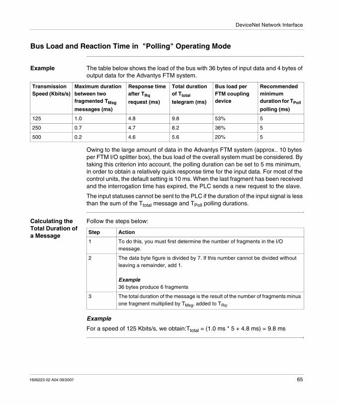
Example The table below shows the load of the bus with 36 bytes of input data and 4 bytes of output data for the Advantys FTM system.
Owing to the large amount of data in the Advantys FTM system (approx.. 10 bytes per FTM I/O splitter box), the bus load of the overall system must be considered. By taking this criterion into account, the polling duration can be set to 5 ms minimum, in order to obtain a relatively quick response time for the input data. For most of the control units, the default setting is 10 ms. When the last fragment has been received and the interrogation time has expired, the PLC sends a new request to the slave.
The input statuses cannot be sent to the PLC if the duration of the input signal is less than the sum of the Ttotal message and TPoll polling durations.
Calculating the Total Duration of a Message
Follow the steps below:
Example
For a speed of 125 Kbits/s, we obtain:Ttotal = (1.0 ms * 5 + 4.8 ms) = 9.8 ms
Transmission Speed (Kbits/s)
Maximum duration between two fragmented TMsg
messages (ms)
Response time after TRq
request (ms)
Total duration of Ttotal
telegram (ms)
Bus load per FTM coupling device
Recommended minimum duration for TPoll
polling (ms)
125 1.0 4.8 9.8 53% 5
250 0.7 4.7 8.2 36% 5
500 0.2 4.6 5.6 20% 5
Step Action
1 To do this, you must first determine the number of fragments in the I/O message.
2 The data byte figure is divided by 7. If this number cannot be divided without leaving a remainder, add 1.
Example36 bytes produce 6 fragments
3 The total duration of the message is the result of the number of fragments minus one fragment multiplied by TMsg, added to TRq.

DeviceNet Network Interface
66 1606223 02 A04 09/2007
Adapting the Polling Duration
A system with a polling duration of 5 ms at 125 Kbits/s is only possible for a coupling device with a bus load of about 53%.
The polling duration must be increased in relation to the size of the system, if a higher transmission speed cannot be selected.
For point-to-point communication with the network master, total polling time can be estimated as Ttotal x3.
For further information on how to optimize communication, see the documentation of the master concerned.

DeviceNet Network Interface
1606223 02 A04 09/2007 67
General Characteristics of the DeviceNet System
Description
Topology Tree structure
Transmission line Cable with 4 twisted and shielded wires, with separate data (white & blue) and power supply (black and red) wires
Cable length Main line max. 500 m (1640.42 ft), branch cables max. 6 m (19.68 ft)
Number of units on the bus max. 64
Number of I/O points Depending on control unit
Addresses One Mac-ID between 0 and 63 per device
Addressing Mac-ID, serial number (32 bits)
Transmission speed Depending on the length (max. 500 Kbits/s)� 500 Kbits/s up to 100 m (328.08 ft) (Thick –Cable)� 250 Kbits/s up to 250 m (820.21 ft) (Thick –Cable)� 125 Kbits/s up to 500 m (1640.42 ft) (Thick –Cable)
Max length of the main line with repeaters: 3 km (9842.49 ft)
Useful data 8 bytes per message
Terminal resistance 121 Ω,at each end of the data line
Error detection Identification of erroneous messages, automatic repetition
Electrical 24 VDC tolerance (global) +/- 4%

DeviceNet Network Interface
68 1606223 02 A04 09/2007
5.3 Behavior
Presentation
Introduction This section addresses the different behavior patterns of the Advantys FTM DeviceNet splitter box.
What's in this Section?
This section contains the following topics:
Topic Page
Behavior at Power-up 69
Behavior for Communication Error 70
Behavior in the Case of Internal Bus Errors 71
Saving and Restoring Parameters 72

DeviceNet Network Interface
1606223 02 A04 09/2007 69
Behavior at Power-up
Description During the initialization phase, the FTM coupling device searches for splitter boxes connected to the internal bus. Once the internal bus has been initialized, the FTM coupling device can communicate on the DeviceNet network.
If there is no back-up configuration, the FTM coupling device initializes the data with the default parameters. When a save has been carried out, the saved parameters are applied during initialization.
If the saved parameters are incompatible with the physical configuration of the splitter boxes connected to the internal bus, then none of the saved parameters are applied: the default parameters are selected. This situation may occur if a splitter box has been replaced by one with another reference number, or if the internal bus has not been properly reconnected after modifications have been performed.

DeviceNet Network Interface
70 1606223 02 A04 09/2007
Behavior for Communication Error
Description In case of communication error the fallback values are applied until the next write on outputs after disappearance of the communication error.
For fallback modes and values, see Discrete Outputs, p. 76 and Analog Outputs, p. 78.

DeviceNet Network Interface
1606223 02 A04 09/2007 71
Behavior in the Case of Internal Bus Errors
Description If an error occurs on the internal bus, the FTM switches to fault mode and stops communicating on the network. Input data can no longer be read and output data can no longer be written.
The last input and output values are frozen.
The fallback values are applied to the outputs.

DeviceNet Network Interface
72 1606223 02 A04 09/2007
Saving and Restoring Parameters
Management of Saved Parameters
During initial power up, the Advantys splitter box is initialized with the default parameters. During subsequent power ups, it is initialized with the saved parameters.
Saving Parameters
The save is controlled by a read access (Set service) with value 1 in attribute 14H of instance 1 of class 64H, user parameter settings.
Restoring Factory Settings
The restoration is controlled by a read access (Set service) with value 1 in attribute 15H of instance 1 of class 64H, user setting delete.
While writing or deleting saved parameters, the node no longer processes communication on the DeviceNet bus. During this operation no message transmitted to the slave is taken into account. The outputs are maintained in their current state and the inputs are not updated.
Note: When the master detects the presence of the splitter box on the network, the parameters of the splitter box that are re-defined in the master's configuration tool are overwritten.
WARNINGRISK OF UNINTENDED EQUIPMENT OPERATION
User must allow for communication delays when writing or deleting parameters.Failure to follow these instructions can result in death, serious injury, or equipment damage.
Note: With the Allen-Bradley RSNetWorx software, before saving or restoring data, you must delete the FTM from the PLC's Scanlist to prevent the FTM from going into error state.

1606223 02 A04 09/2007 73
6Application-Specific Functions
At a Glance
Introduction Depending on its version, the FTM splitter box offers discrete input, output and diagnostics channels and discrete input or output for configurable channels. This following chapter describes the operating modes for these different channels.
What's in this Chapter?
This chapter contains the following topics:
Topic Page
Application-Specific Functions Description 74
Discrete I/Os description 75
Description of Analog I/Os 77
Measurement Ranges and Scales 79
Splitter box Channel Types 82
Application-Specific Functions
74 1606223 02 A04 09/2007
Application-Specific Functions Description
Available Types of Channels
The Advantys FTM range offers a wide selection of discrete and analog I/O splitter boxes. The following chapter describes the operation of the I/Os and configuration data.
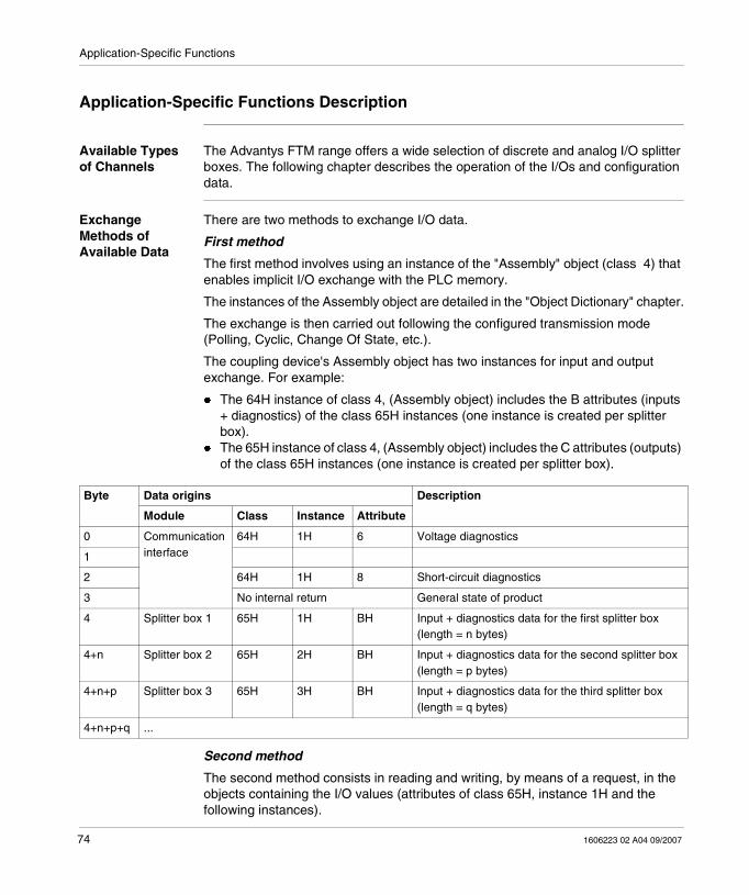
Exchange Methods of Available Data
There are two methods to exchange I/O data.
First method
The first method involves using an instance of the "Assembly" object (class 4) that enables implicit I/O exchange with the PLC memory.
The instances of the Assembly object are detailed in the "Object Dictionary" chapter.
The exchange is then carried out following the configured transmission mode (Polling, Cyclic, Change Of State, etc.).
The coupling device's Assembly object has two instances for input and output exchange. For example:
� The 64H instance of class 4, (Assembly object) includes the B attributes (inputs + diagnostics) of the class 65H instances (one instance is created per splitter box).
� The 65H instance of class 4, (Assembly object) includes the C attributes (outputs) of the class 65H instances (one instance is created per splitter box).
Second method
The second method consists in reading and writing, by means of a request, in the objects containing the I/O values (attributes of class 65H, instance 1H and the following instances).
Byte Data origins Description
Module Class Instance Attribute
0 Communication interface
64H 1H 6 Voltage diagnostics
1
2 64H 1H 8 Short-circuit diagnostics
3 No internal return General state of product
4 Splitter box 1 65H 1H BH Input + diagnostics data for the first splitter box (length = n bytes)
4+n Splitter box 2 65H 2H BH Input + diagnostics data for the second splitter box (length = p bytes)
4+n+p Splitter box 3 65H 3H BH Input + diagnostics data for the third splitter box (length = q bytes)
4+n+p+q ...

Application-Specific Functions
1606223 02 A04 09/2007 75
Discrete I/Os description
Configurable channels
The configurable splitter box discrete channels can be used as inputs or outputs. (They are configured as inputs by default).
Channels 10 to 17 of discrete splitter boxes (pin 2 on M12 connectors) can be configured as "diagnostics inputs" for monitoring sensors or actuators equipped with a diagnostics function (DESINA).
Discrete Inputs The inputs can be reversed in order to be used in NO or NC.
Channels 10 to 17 (pin 2 of M12 connectors) can be configured as "diagnostics inputs".
The status read on inputs is defined as follows:
Channels 00 to 07 are configured as "NO input" by default (no reversal).
Channels 10 to 17 are configured as "diagnostics input" by default (no reversal).
ToggleConfiguration
Input
Input readInput diagnostics
Polarity
NO/NCClass 65HAttributes 14H
Class 65HAttribute 2CH (M12) or 41H (M8)
of Class 65HAttribute 28H

Application-Specific Functions
76 1606223 02 A04 09/2007
Discrete Outputs In the event of communication errors with the bus master, the FTM assigns the user-configured status to the outputs:
� maintaining the last value,� fallback to 0 (mode by default),� fallback to 1
Toggle
Togglein the event
of error
Fallback mode
Fallback value
Command
OutputClass 65HAttribute 1EH
Class 65HAttribute 2AH (M12)Attribute 40H (M8)
Class 65HAttribute 2BH (M12)Attribute 41H (M8)

Application-Specific Functions
1606223 02 A04 09/2007 77
Description of Analog I/Os
Analog inputs Analog inputs are read by 16 bit words.
The status read on inputs is defined as follows:
Smoothing the Input Value
The analog signal can be pre-filtered in the device, to reduce temporary measurement variations for example.
The measurement time is 2 ms per channel. The total cycle time is the result of the measurement time for each channel + 2.5 ms.
The following diagram shows the behavior of the module in relation to the response time on an active channel.
A/Dconverter Line conditioning Input read
Type of analoginput
Analoginput
Class 65HAttributes 28H...2BH
Class 65HAttributes 14H...17H
LowMediumHigh
Response in ms
0
90%
100%
500 2000
0%

Application-Specific Functions
78 1606223 02 A04 09/2007
Using Delta The delta value is used to define a deadband, within which input signal value changes will not be reported. This is used to avoid a bus overload if data is transmitted for a change in value.
The delta value is expressed as a number of input points on a gross measurement scale. (See the tables above for a view of the scales according to configuration).
Example
If the final measurement value was 1000 points. by then adjusting the delta value to 100, a new measurement value will only be sent if less than 900 or greater than 1100.
The delta value must be between 0 and 32 767.
Analog Outputs In the event of communication errors with the bus master, the splitter box assigns the user-configured status to the outputs:
� maintaining the last value,� Fallback to a preset value
The status applied on the output is defined as follows:
Line conditioning D/Aconverter
Analogoutput
Analogoutput
Fallback mode
Fallback value
Toggle if 0H
Toggle in the event of error
Output command
Class 65HAttributes 28H...2BH
Class 65HAttributes 1EH...21H
Class 65HAttributes 2CH...2FH
Class 65HAttributes 30H...33H

Application-Specific Functions
1606223 02 A04 09/2007 79
Measurement Ranges and Scales
FTM 1AE04C12T range 0...10 VDC
Measurement range of analog input (15 bits resolution):
FTM 1AE04C12T range +/-10 VDC
Measurement range of analog input (resolution : 15 bits + 1 sign bit):
Measurement range
Binary value Hexadecimal value
Decimal value Zone Diagnostics
> 10 VDC 0111 1111 1111 1111 7FFF 32 767 Greater than yes
10 VDC 0111 1111 1111 1111 7FFF 32 767 Nominal range -
5 VDC 0011 1111 1111 1111 3FFF 16 383 Nominal range -
0.305 mVDC 0000 0000 0000 0001 0001 1 Nominal range -
0 VDC 0000 0000 0000 0000 0000 0 Nominal range -
< 0 VDC 0000 0000 0000 0000 0000 0 Less than -
Measurement range
Binary value Hexadecimal value
Decimal value Zone Diagnostics
> 10 VDC 0111 1111 1111 1111 7FFF 32 767 Greater than yes
10 VDC 0111 1111 1111 1111 7FFF 32 767 Nominal range -
5 VDC 0011 1111 1111 1111 3FFF 16 383 Nominal range -
0.305 mV 0000 0000 0000 0001 0001 1 Nominal range -
0 VDC 0000 0000 0000 0000 0000 0 Nominal range -
-0.305 mV 1111 1111 1111 1111 FFFF -1 Nominal range -
-5 VDC 1100 0000 0000 0001 C000 -16 383 Nominal range -
-10 VDC 1000 0000 0000 0000 8000 -32 767 Nominal range -
<-10 VDC 1000 0000 0000 0000 8000 -32 767 Less than yes

Application-Specific Functions
80 1606223 02 A04 09/2007
FTM 1AE04C12C range 0...20 mA
Measurement range of analog input (15 bits resolution):
FTM 1AE04C12C range 4...20 mA
Measurement range of analog input (15 bits resolution):
FTM 1AS04C12T range 0...10 VDC
Measurement range of analog output (11 bits resolution):
Measurement range
Binary value Hexadecimal value
Decimal value Zone Diagnostics
> 20 mA 0111 1111 1111 1111 7FFF 32 767 Greater than yes
20mA 0111 1111 1111 1111 7FFF 32 767 Nominal range -
10 mA 0011 1111 1111 1111 3FFF 16 383 Nominal range -
4 mA 0001 1001 1001 1001 1999 6553 Nominal range -
0 mA 0000 0000 0000 0000 0000 0 Nominal range -
< 0 mA 0000 0000 0000 0000 0000 0 Less than -
Measurement range
Binary value Hexadecimal value
Decimal value Zone Diagnostics
> 20 mA 0111 1111 1111 1111 7FFF 32 767 Greater than yes
20mA 0111 1111 1111 1111 7FFF 32 767 Nominal range -
10 mA 0010 1111 1111 1010 2FFA 16 383 Nominal range -
4 mA 0000 0000 0000 0000 0000 0 Nominal range -
< 4 mA 0000 0000 0000 0000 0000 0 Less than Break in cable < 2 mA and/or Overrun of lower threshold < 4 mA
Output range Binary value Hexadecimal value
Decimal value Zone
10 VDC 0111 1111 1111 xxxx 7FFx 32 752...32 767 Nominal range
5 VDC 0011 1111 1111 xxxx 3FFx 16 368...16 383 Nominal range
0.305 mVDC 0000 0000 0000 xxxx 000x 0...15 Nominal range
0 VDC 0000 0000 0000 xxxx 000x 0...15 Nominal range

Application-Specific Functions
1606223 02 A04 09/2007 81
FTM 1AS04C12T range +/-10 VDC
Measurement range of analog output (resolution: 11 bits + 1 sign bit):
FTM 1AS04C12C range 0...20 mA
Measurement range of analog output (11 bits resolution):
FTM 1AS04C12C range 0...20 mA
Measurement range of analog output (11 bits resolution):
Output range Binary value Hexadecimal value
Decimal value Zone
10 VDC 0111 1111 1111 xxxx 7FFx 32 752...32 767 Nominal range
5 VDC 0011 1111 1111 xxxx 3FFx 16 368...16 383 Nominal range
0.305 mV 0000 0000 0000 xxxx 000x 1...15 Nominal range
0 VDC 0000 0000 0000 xxxx 000x 0 Nominal range
-0.305 mVDC 1111 1111 1111 xxxx FFFx -1...-15 Nominal range
-5 VDC 1100 0000 0000 xxxx C00x -16 383...-16 368 Nominal range
-10 VDC 1000 0000 0000 xxxx 800x -32 767...-32 752 Nominal range
Output range Binary value Hexadecimal value
Decimal value Zone
20 mA 0111 1111 1111 xxxx 7FFx 32 752...32 767 Nominal range
10 mA 0011 1111 1111 xxxx 3FFx 16 368...16 383 Nominal range
4 mA 0001 1001 1001 xxxx 199x 6544...6553 Nominal range
0 mA 0000 0000 0000 xxxx 000x 0...15 Nominal range
Output range Binary value Hexadecimal value
Decimal value Zone
20 mA 0111 1111 1111 xxxx 7FFF 32 767 Nominal range
10 mA 0010 1111 1111 xxxx 2FFx 12 272...12 287 Nominal range
4 mA 0000 0000 0000 xxxx 000x 0...15 Nominal range
Note: The sub-index of write analog output for object 6411H (Write Analog Output 16 bits) are in 16-bit format and the resolution of A/N convertors is 12 bits, which causes non-significant values to appear.

Application-Specific Functions
82 1606223 02 A04 09/2007
Splitter box Channel Types
Description The table below shows the types of channels available for each splitter box:
Splitter box Discrete Inputs Configurable discrete channels
Analog inputs Analog Outputs
FTM 1DE16C12• 00...0710...17
- - -
FTM 1DE08C12• 00...0310...17
- - -
FTM 1DE08C08• 00...07-
- - -
FTM 1DD16C12• - 00...0710...17
- -
FTM 1DD08C12• - 00...0310...17
- -
FTM 1DD08C08• - 00...07 - -
FTM 1AE04C12T - - 4 (Voltage) -
FTM 1AE04C12C - - 4 (Current) -
FTM 1AS04C12T - - - 4 (Voltage)
FTM 1AS04C12C - - - 4 (Current)

1606223 02 A04 09/2007 83
7Software Installation
At a Glance
Introduction This chapter provides all necessary elements for software installation of Advantys FTB and FTM splitter boxes.
What's in this Chapter?
This chapter contains the following topics:
Topic Page
Possible Configurations 84
Step-by-Sep Procedure 85
Configuring the Splitter Boxes Associated to the FTM 1DN10 Coupling Device 88

Software Installation
84 1606223 02 A04 09/2007
Possible Configurations
Description Generally, configuration is carried out using a help software tool like the Allen-Bradley RSNetWorx during configuration.
However, the parameters can also be modified from the user program via explicit requests directed to the attributes of class 65H containing the configuration words. For further information on this subject, see the "Object Dictionary" chapter.

Software Installation
1606223 02 A04 09/2007 85
Step-by-Sep Procedure
Description The Advantys FTM splitter box is installed on the field bus using the DeviceNet scanner. The scanner searches for DeviceNet units on the network. To ensure correct recognition, the EDS files of the Advantys FTM splitter boxes should be placed in the scanner software beforehand.
If devices were addressed to the bus using a software, they must always be connected to the bus in a sequential manner since they all have the same MAC-ID by default!
Once the system is completely configured and bus communication is activated, other devices can be added to the bus provided that their MAC-ID (address) and transmission speed are correctly configured.
The typical errors that occur during installation are: Bus line damage, incorrect transmission speed, twice assigned MAC-ID, inversion of CAN_H and CAN_L on the bus line, no power supply (back up power supply), bus termination incorrect, No EDS file or EDS file errors.
Note: The units with the same MAC-ID will not complete the MAC-ID test. At the end of the self-test, the NS LED lights up red. Each device type has its own EDS file (*.eds) + icon (*.ico). These files are located on the FTX ES0• CD or at http://www.telemecanique.com.

Software Installation
86 1606223 02 A04 09/2007
Example of Scanlist using the Allen-Bradley RSNetWorx software:
*DeviceNet.dnt - RSNetWorx for DeviceNet
File Edit View Network Device Diagnostics Tools Help
?
?
0
1
2
3
0
1
2
3
I/O 12/4I/O 6/0
1747-SDNScannerModule
FTB 1DN16EP0 FTB1DN12E04SP0
FTM1DN10 1770-KFDRS232 Interface
02 09
I/O 16/0
20 30 62
FTB1DN08E08SPO
Spreadsheet Master/Slave Configuration Diagnostics
Mes
sage
s
Ready
Graph
Message Code Date DescriptionDNET:0101 06/07/2003 15:38:02 Mode changed to online. The online path is CZ3131QQ8!17i
04

Software Installation
1606223 02 A04 09/2007 87
Operating mode Installing with Allen-Bradley SLC 5/03 software, KFD-Box 1770-KFD (RSNetWorx for DN) and an Allen-Bradley 1747-SDN scanner:
Step Action
1 Connect one or several devices to the DeviceNet bus (make sure its composition is appropriate for the field bus).
2 Apply the power supply voltage to the units on the bus (check the voltage beforehand).
3 The scanner will first conduct a self-test and display the corresponding status messages (on the display: "80"). After the scanner starts up, "00" and "75" flash alternately on the display.The status of the scanner is also shown by 2 LEDs located on the scanner; these two LEDs indicate the status of the DeviceNet bus (Ok or NOK) and the status of the module (scanner error after start-up without module unit= green, Net = flashing green). When there are units on the bus, the LEDs remain unchanged but the "00" and "76" messages blink alternately on the display.
4 At this time, the FTM coupling devices also show their status via the bus LEDs (MS = green and NS = flashing green).
5 Connect the KFD-Box to the field bus and the PC and launch the RSNetWorx software tool. In the RSNetworx task bar, press the "Online" button and validate certain safety messages; the program will then start scanning the network via theKFD-Box (it must be defined beforehand that the network will be scanned by the KFD-box).At this time all the units that are correctly connected to the bus are displayed!
6 Ensure that all the bus units have been detected and are correctly registered in the scanner's Scan list.
7 Click on the "Register Scanlist" button and confirm with the "Download"button.In the new Windows window, press the ">>" button then "open" and download in the scanner's Scan list.
8 All the modules are now registered in the scanner's Scan list (this is also indicated by the status LEDs of the FTp 1DNppp and scanner: FTp 1DNppp = green MS and NS, Scanner = module and green Net ) and the module data can be accessed using the PLC depending on the established Scan list.
Step Action
1 Change the EDS files and icons using the FTX ES0• CD-Rom.
2 Connect the FTM coupling device to the DeviceNet Bus.
3 Switch on the system.
4 Configure the products.

Software Installation
88 1606223 02 A04 09/2007
Configuring the Splitter Boxes Associated to the FTM 1DN10 Coupling Device
Operating mode After installing the network as previously indicated, the parameters of the splitter boxes on the network must then be configured.
The parameters are acknowledged only after their validation.
Before saving data, delete the coupling device from the Scan list of your PLC to prevent it from displaying an error. The coupling device will not respond to any request from the master during the writing phase.
Follow the steps below:
Step Action
1 Remove the FTM 1DN10 module from the scanlist.
*DeviceNet.dnt - RSNetWorx for DeviceNet
File Edit View Network Device Diagnostics Tools Help
?
?
I/O 12/4
FTB 1DN16EP0 FTB1DN12E04SP0
FTM1DN10 1770-KFDRS232 Interface
09
I/O 16/0
20 30 62
FTB1DN08E08SPO
Spreadsheet Master/Slave Configuration Diagnostics
Mes
sage
s
Allen-Bradley 1747-SDN Scanner Module
Graph
Message Code Date DescriptionDNET:0101 06/07/2003 15:38:02 Mode changed to online. The online path is CZ3131QQ8!17i
04
1747-SDNScannerModule
I/O 6/0
02
1747-SDN Scanner Mobile
General Module Scanlist Input Output ADR Summary
Available Devices: Scanlist:
04, FTB 1DN08E08SP0I/O 6/0
09, FTB 1DN16EP0I/O 16/0
20, FTB 1DN12E04SP0I/O 12/4
Automap on Add
Upload from Scanner...
Download to Scanner...
Edit I/O Parameters...Edit I/O Parameters...
Node ActiveNode ActiveElectronic Key
Device TypeDevice TypeVendorVendorProduct CodeProduct CodeMajor RevisionMajor RevisionMinorMinor or higheror higher
OK Cancel Apply Help
30, FTM1DN10
?

Software Installation
1606223 02 A04 09/2007 89
2 Click Ok.
Step Action
*DeviceNet.dnt - RSNetWorx for DeviceNet
File Edit View Network Device Diagnostics Tools Help
?
?
I/O 12/4
FTB 1DN16EP0 FTB1DN12E04SP0
FTM1DN10 1770-KFDRS232 Interface
09
I/O 16/0
20 30 62
FTB1DN08E08SPO
Spreadsheet Master/Slave Configuration Diagnostics
Mes
sage
s
Allen-Bradley 1747-SDN Scanner Module
Graph
Message Code Date DescriptionDNET:0101 06/07/2003 15:38:02 Mode changed to online. The online path is CZ3131QQ8!17i
04
1747-SDNScannerModule
I/O 6/0
02
1747-SDN Scanner Mobile
General Module Scanlist Input Output ADR Summary
Available Devices: Scanlist:
04, FTB 1DN08E08SP0I/O 6/0
09, FTB 1DN16EP0I/O 16/0
20, FTB 1DN12E04SP0I/O 12/4
Automap on Add
Upload from Scanner...
Download to Scanner...
Edit I/O Parameters...Edit I/O Parameters...
Node ActiveNode ActiveElectronic Key
Device TypeDevice TypeVendorVendorProduct CodeProduct CodeMajor RevisionMajor RevisionMinorMinor or higheror higher
OK Cancel Apply Help
30, FTM1DN10
?

Software Installation
90 1606223 02 A04 09/2007
3 � Declare all the splitter boxes connected to the coupling device following the ramification order.� Select the splitter box to be configured.� In the "Advanced parameters" tab, modify the parameters.
Example� Click "Failsafe mode".� Check the fallback values desired for each channel.� Click Ok.
Step Action
*DeviceNet.dnt - RSNetWorx for DeviceNet
File Edit View Network Device Diagnostics Tools Help
?
?
I/O 12/4
FTB 1DN16EP0 FTB1DN12E04SP0
1770-KFDRS232 Interface
09
I/O 16/0
20 30 62
FTB1DN08E08SPO
Spreadsheet Master/Slave Configuration Diagnostics
Mes
sage
s
Schneider Automation, Inc. FTM1DN10
Graph
Message Code Date DescriptionDNET:0101 06/07/2003 15:38:02 Mode changed to online. The online path is CZ3131QQ8!17i
04
I/O 6/0
02
1747-SDNScannerModule
FTM1DN10
Slot ’03’ - FTM1DD16C12
General Configuration Settings EDS File
OK Cancel Help
Select the parameter that you want to configure and initiale an action using the toolbar
?
Restorexyz xy Help?
2 Modulcode 56600 No.1 Modul Identity
4 Cube Orerating State Modul Operational3 Revision Number
11 Input/Output 11111111 1111111110 Diagnosis/Input
131073
FTM1DD12C12
11111111 00000000
29 Force Output 00-17 10100101 10100101
13 Failsafevalue 00000000 1111111114 Input Function NO/NC 00000000 00000000
...12 Failsafemode 11111111 11111111
...
Parameter Current Value
FTM1DN10
General Module Configuration I/O Summary
Hardware
OK Cancel Apply Help
FMT 1AS04C12T
FMT1AE04C12C
FMT1AE04C12T
FMT1AS04C12T
FMT1DD08C08
FMT1DD08C08E
FMT1DD08C2
CUBE67D016EValve
Upload
Download
Properties
Chassis Type: Display Hardware
Select and configure the adapter, and associated modules, that reside in the current chassis.
Product NameCube67 Chassis
FTM1DN10
Module TypeSlot
n/a
FTM1DE08C12E00
FTM1DE08C0801
FTM1DE16C1202
FTM1DD16C1203
FTM1DD08C12E04
FTM1DD08C0805
06
07
?
......
...
...
...
31 Number of Diagnostic +...... 00000000 0000000130 State of Inputs 00-17 00000000 00000000 ...
...32 Collectiv + Short Circuit 00000000 00000000 ...
OK Cancel
Pin4, last State oder State value 00
Failsafemode
Pin4, last State oder State value 01Pin4, last State oder State value 02Pin4, last State oder State value 03Pin4, last State oder State value 04Pin4, last State oder State value 05Pin4, last State oder State value 06Pin4, last State oder State value 07Pin2, last State oder State value 10Pin2, last State oder State value 11Pin2, last State oder State value 12Pin2, last State oder State value 13Pin2, last State oder State value 14Pin2, last State oder State value 15Pin2, last State oder State value 16Pin2, last State oder State value 17

Software Installation
1606223 02 A04 09/2007 91
4 In the drop-down list to the right of the "Set parameters" parameter, select "Save all Parameters" and click OK.
Step Action
I/O 12/4
FTB 1DN16EP0 FTB1DN12E04SP0
1770-KFDRS232 Interface
09
I/O 16/0
20 30 62
FTB1DN08E08SPO
Spreadsheet Master/Slave Configuration Diagnostics
Mes
sage
s
Schneider Automation, Inc. FTM1DN10
Graph
Message Code Date DescriptionDNET:0101 06/07/2003 15:38:02 Mode changed to online. The online path is CZ3131QQ8!17i
04
I/O 6/0
02
1747-SDNScannerModule
FTM1DN10
Slot ’n/a’ - FTM1DN10
General Configuration Settings EDS File
OK Cancel Help
Select the parameter that you want to configure and initiale an action using the toolbar
?
GroupsGroups Restorexyz xy Help?
2 Partnumber Cube 42103 Art.No.1 Modul Identity
4 Hardware Revision 1.00 HW3 Cube67-BN S/N Number
6 Amount all I/O-Boxes 6 I/O Boxes5 Software Revision
4294967295 S/N
1.00 SW
7 Amount all Pin4 & Pin2 64 unit8 Busnode diagnosis 00000000 000000009 Busnode Short circuit di... 00000000
...
10 Set Parameters
ID Parameter Current Value
FTM1DN10
General Module Configuration I/O Summary
Hardware
OK Cancel Apply Help
FMT 1AS04C12T
FMT1AE04C12C
FMT1AE04C12T
FMT1AS04C12T
FMT1DD08C08
FMT1DD08C08E
FMT1DD08C2
CUBE67D016EValve
Upload
Download
Properties
Chassis Type: Display Hardware
Select and configure the adapter, and associated modules, that reside in the current chassis.
Product NameCube67 Chassis
FTM1DN10
Module TypeSlot
n/a
FTM1DE08C12E00
FTM1DE08C0801
FTM1DE16C1202
FTM1DD16C1203
FTM1DD08C12E04
FTM1DD08C0805
06
07
?
Parameters not Stored
Parameters not Stored
Save all Parametres
...

Software Installation
92 1606223 02 A04 09/2007
5 Replace the FTM coupling device in the scanlist.
Step Action
*DeviceNet.dnt - RSNetWorx for DeviceNet
File Edit View Network Device Diagnostics Tools Help
?
?
I/O 12/4
FTB 1DN16EP0 FTB1DN12E04SP0
FTM1DN10 1770-KFDRS232 Interface
09
I/O 16/0
20 30 62
FTB1DN08E08SPO
Spreadsheet Master/Slave Configuration Diagnostics
Mes
sage
s
Allen-Bradley 1747-SDN Scanner Module
Graph
Message Code Date DescriptionDNET:0101 06/07/2003 15:38:02 Mode changed to online. The online path is CZ3131QQ8!17i
04
1747-SDNScannerModule
I/O 6/0
02
1747-SDN Scanner Mobile
General Module Scanlist Input Output ADR Summary
Available Devices: Scanlist:
04, FTB 1DN08E08SP0I/O 6/0
09, FTB 1DN16EP0I/O 16/0
20, FTB 1DN12E04SP0I/O 12/4
Automap on Add
Upload from Scanner...
Download to Scanner...
Edit I/O Parameters...Edit I/O Parameters...
Node ActiveNode ActiveElectronic Key
Device TypeDevice TypeVendorVendorProduct CodeProduct CodeMajor RevisionMajor RevisionMinorMinor or higheror higher
OK Cancel Apply Help
30, FTM1DN10
?

1606223 02 A04 09/2007 93
8Diagnostics
At a Glance
Introduction Diagnostics information simplifies installation and accelerates error searching.
This chapter provides the elements necessary for diagnostics by:
� LED display,
� Software.
What's in this Chapter?
This chapter contains the following topics:
Topic Page
Power supply diagnostics 94
Field Bus Status Diagnostics LED 96
Internal Bus Diagnostics LEDs 97
Discrete I/O Diagnostics LEDs 98
Analog I/O Diagnostics LEDs 99
Software Diagnostics 100
Behavior in the Event of Short-circuit / Overload / Under-voltage 101

Diagnostics
94 1606223 02 A04 09/2007
Power supply diagnostics
Description The status of the power supply can be read from the internal bus connectors on the coupling device and on the splitter boxes.
Position of LEDs on the module and splitter boxes:
LED Meaning
UA Actuator power supply diagnostics LED
US Detector power supply diagnostics LED
Note: The color of the LED depends on the power supply, as described in the following tables.
US UA0
US UA
1
3
US UA2 US UA
0 1 4 0 1
5
7
0 1 6 0 1
0 1 0 0 1
1
3
0 1 2 0 1
UA US UAUS
US UA
MS NS

Diagnostics
1606223 02 A04 09/2007 95
Detector Power Supply Status
The status of the detector power supply is specified in the following table:
Actuator Power Supply Status
The status of the actuator power supply is specified in the following table:
LED description
LED status Description
US Green Correct (> 18 VDC)
US Red Under-voltage or short-circuit on detector power supply
US Off No power supply or power supplied to detectors < 12.5 VDC
LED description
LED status Description
UA Green Correct (> 18 VDC)
UA Red Under-voltage or short-circuit on actuator power supply
UA Off No power supply or power supplied to actuators < 12.5 VDC
Note: The display for the power supply status of actuators external to the FTM 1DD16C12 is identical.

Diagnostics
96 1606223 02 A04 09/2007
Field Bus Status Diagnostics LED
Display description
Position of the MS and NS LEDs on the front panel:
LED/MS
LED/NS
*Dup-Mac test: Duplicate MAC-ID test
0 US UA
1
3
US UA 2 US UA
US UA
MS NS
MS NS
Display Status Meaning
Off The self-testing is not finished
Green The self-testing is finished
Display Status Meaning
Off The Dup-Mac test* is not finished.No other bus elements in the DeviceNet network.
Blinking green The Dup-Mac test* is not finished.No link with the master.
Green Link established with the master (explicit link and/or I/O link).
Blinking red No more connection with the (Timeout master, bus link interrupted).
Red Bus link interrupt, physical fault on the bus (voltage reset required).

Diagnostics
1606223 02 A04 09/2007 97
Internal Bus Diagnostics LEDs
Position of LEDs The position of the US and UA LEDs are specified in the following diagram:
Internal Bus Communication Status
The status of system communication at the module is specified in the following table:
US UA0
US UA
1
3
US UA2
US UA
0 1 4 0 1
5
7
0 1 6 0 1
0 1 0 0 1
1
3
0 1 2 0 1
UA US UAUS
US UA
MS NS
LED description Display behavior LED status
US Permanently switched on
Data exchange
US Flashing No data exchange:communication has been interrupted on at least one branch.
US Off No communication:No splitter box is connected or the detector power supply has been cut off.

Diagnostics
98 1606223 02 A04 09/2007
Discrete I/O Diagnostics LEDs
Position of LEDs The position of the LEDs for each channel are specified in the following diagram:
LED Behavior LED behavior according to settings and channel status:
0 1 4 0 1
5
7
0 1 6 0 1
0 1 0 0 1
1
3
0 1 2 0 1
UA UAddr. UAUAddr.
0 1
LED Channel
LED Channel
00…07 10…17
Channel configuration Input voltage Logical value LED status
Input closing function 0 VDC 0 Off
24 VDC 1 Yellow
Channel error - Red
Input opening function 0 VDC 1 Off
24 VDC 0 Yellow
Channel error - Red
Input diagnostics 0 VDC 1 Red
24 VDC 0 Off
Output 0 VDC 0 Off
24 VDC 1 Yellow
Channel error - Red
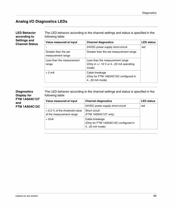
Diagnostics
1606223 02 A04 09/2007 99
Analog I/O Diagnostics LEDs
LED Behavior according to Settings and Channel Status
The LED behavior according to the channel settings and status is specified in the following table:
Diagnostics Display for FTM 1AS04C12T and FTM 1AS04C12C
The LED behavior according to the channel settings and status is specified in the following table:
Value measured at input Channel diagnostics LED status
- 24VDC power supply short-circuit red
Greater than the set measurement range
Greater than the set measurement range
Less than the measurement range
Less than the measurement range(Only in +/- 10 V or 4...20 mA operating mode)
< 2 mA Cable breakage(Only for FTM 1AE04C12C configured in 4...20 mA mode)
Value measured at input Channel diagnostics LED status
- 24VDC power supply short-circuit red
< 0.3 % of the threshold value of the measurement range
Short circuit (FTM 1AS04C12T only)
> 2mA Cable breakage(Only for FTM 1AS04C12C configured in 4...20 mA mode)

Diagnostics
100 1606223 02 A04 09/2007
Software Diagnostics
Description There are two methods for reading diagnostic data:
� The first method involves using an instance of the "Assembly" object (class 4) that enables implicit I/O exchange with the PLC memory. The reading is therefore directly done in the PLC's image memory.
� The second method involves reading the objects containing the diagnostics by requests (classes 64 and 65).
Using the "Assembly" Object
The Assembly object contains the diagnostic data of the coupling device, followed by attributes B and D of class 65H, that correspond to the different connected splitter boxes.
The structure of the input data is given in the description of the Class 5H, Instance 64H, p. 115 object.
Reading Objects by Requests
The diagnostic objects concerning the communication interface are as follows (class 64H, instance 1H):
� Attribute5: List of splitter box diagnostics. (1 byte per splitter box)� Attribute 6: Voltage error on the connectors coming from the internal bus. � Attribute 8: Short-circuit fault on the connectors leaving from the internal bus.
The diagnostic objects concerning the splitter boxes are as follows (class 65H, attribute 51H and following attributes):
General diagnostics
Signals the type of faults present on the splitter box.
DESINA Diagnostics Bytes
DESINA diagnostics is indicated for channels 10 to 17 (or 0 to 7) where they are configured as diagnostics inputs.
Actuator Stop
Actuator stop reported following short circuit on discrete output-configured channel.
Actuator overload
Actuator overload is reported if discrete output receives > 11 V power supply while set to 0.

Diagnostics
1606223 02 A04 09/2007 101
Behavior in the Event of Short-circuit / Overload / Under-voltage
Sensors Short-circuit / overload
The following consequences on the FTM splitter box occur when the sensor power supply experiences a short-circuit or overload:
� The diagnostics LED on the corresponding M12 connector lights up red,� corresponding diagnostics data is transmitted to the master via the bus,� all other inputs and outputs will continue to operate correctly.
Disconnecting the M12 connector of the faulty channel results in LED and diagnostics data re-initialization.
Under-voltage / no voltage
There are three under-voltage detection levels:
� 12 VDC ≤ U < 18 VDC: in this case, the splitter box still operates, although:� the LED U A is red,� appropriate diagnostics data is sent to the master via the bus
� 7 VDC ≤ U < 12 VDC: in this case, the I/Os no longer operate, however bus communication remains operational:� the LED U A is switched off,� the relevant diagnostics data is sent to the master via the bus.
� U < 7 VDC : in this case, the splitter no longer operates.
Actuators Short-circuit / overload
The following consequences on the FTM splitter box occur when an output experiences a short-circuit or overload:
� The diagnostics LED on the corresponding M12 connector lights up red,� the output status LED lights up red.� the corresponding diagnostics data is transmitted to the master via the bus.
To be re-activated, a default output must be set to 0 after clearing the error.
Under-voltage / no voltage
There are two under-voltage detection levels:
� 12 VDC ≤ U < 18 VDC: in this case, the splitter box still operates, however:� the LED U S is red,� the relevant diagnostics data is sent to the master via the bus.
� U < 12 VDC:� the LED US switches off,� the relevant diagnostics data is sent to the master via the bus.
Note: Sensor power supply is provided by the M12 connectors between pins 1 (+24 VDC) and 3 (0 VDC).

Diagnostics
102 1606223 02 A04 09/2007

1606223 02 A04 09/2007 103
9Object Dictionary
At a Glance
Description This chapter provides a description of the object dictionary, as well as the list of objects used by DeviceNet.
What's in this Chapter?
This chapter contains the following sections:
Section Topic Page
9.1 Structure of Objects 105
9.2 Class 1H, Identity object 108
9.3 Class 2H, Message Router Object 110
9.4 Class 3H, DeviceNet Object 111
9.5 Class 4H, Assembly Object 113
9.6 Class 5H, Connection Object 117
9.7 Class 2BH, Acknowledge handler Object 120
9.8 Class 64H, Coupling Device Configuration 122
9.9 Class 65H, Splitter Boxes 125

Object Dictionary
104 1606223 02 A04 09/2007

Object Dictionary
1606223 02 A04 09/2007 105
9.1 Structure of Objects
Presentation
Description The I/O splitter box data are assembled in the accessible objects via the FTM 1DN10 coupling device. They are presented in the section that follows.
What's in this Section?
This section contains the following topics:
Topic Page
General Structure of Objects 106
Class Summary 107

Object Dictionary
106 1606223 02 A04 09/2007
General Structure of Objects
Description An object is a set of data called "Attributes". The attributes of objects are organized in a structured model called a "Class".
For each object, a class defines the organization of the attributes, their types and the access methods or "Utilities" allowed.
This model can then be instanced in an iterative manner.
For example, if 2 identical I/O splitter boxes are connected to the coupling device , two sets of data organized in the same manner but which contain different values will be implemented. There will be two instances of the same class, each containing a set of attributes with different values.
For certain objects, the instances can contain different attributes. It is the case for the standard objects used for communication or for the configuration object.
Utilities The following table describes the supported services for accessing data:
Code (Hexadecimal)
Abbreviation Name Description
05 Reset Reset Default values applied
0E Get Get_single_attribut Reading data
10 Set Set_single_attribut Writing data
16 Save Save Saving parameters

Object Dictionary
1606223 02 A04 09/2007 107
Class Summary
Description The classes used by the FTM DeviceNet splitter boxes are listed in the table below:
Class (Hexadecimal)
Name Contents
1 Identity Product information
2 Message router Used for explicit messages
3 DeviceNet Network communication function characteristics
4 Assembly Groups the splitter box data for operation by user application (data exchanged in implicit manner)
5 Connection Defines the data transmission mode
2B Acknowledge handler Acknowledgement management
64 Coupling device Data specific to the coupling device
65 Splitter boxes Data specific to splitter boxes

Object Dictionary
108 1606223 02 A04 09/2007
9.2 Class 1H, Identity object
Description
At a Glance The Identity object contains general information on the distributor used.
What's in this Section?
This section contains the following topics:
Topic Page
Class 1H: Instance 0H 109
Class 1H: Instance 1H 109

Object Dictionary
1606223 02 A04 09/2007 109
Class 1H: Instance 0H
Description
Class 1H: Instance 1H
Description
Attribute (Hexadecimal)
Name Utilities Type Description
1 Revision Get UINT Revision of the object definition
2 Max. instance Get UINT Max number of instances
Attribute (Hexadecimal)
Name Utilities Type Description Notes
1 Vendor ID Get UINT Manufacturer's identification code 243H
2 Device Type Get UINT Product profile Communication interface
3 Product Code Get UINT Product code 56502
4 Revision Get STRUCT OF Object revision
Major Revision Get USINT 02
Minor Revision Get USINT 02
5 Status Get UDINT Communication status
6 Serial Number Get UDINT Serial number
7 Product Name Get SHORT STRING
FTM1DN10
10 Heartbeat interval
Get / Set USINT Period between two messages Heartbeat
In seconds

Object Dictionary
110 1606223 02 A04 09/2007
9.3 Class 2H, Message Router Object
Attributes and Available Services
Description This object has neither attribute nor available service.

Object Dictionary
1606223 02 A04 09/2007 111
9.4 Class 3H, DeviceNet Object
At a Glance
Description The DeviceNet object contains the device's general communication characteristics.
At power up, the device address is read on the rotary switches and the transmission speed is automatically detected. Data is then saved in the RAM.
What's in this Section?
This section contains the following topics:
Topic Page
Class 3H: Instance 0H 112
Class 3H: Instance 1H 112

Object Dictionary
112 1606223 02 A04 09/2007
Class 3H: Instance 0H
Description
Class 3H: Instance 1H
Description
Attributes Name Utilities Type Description Notes
1 Revision Get UINT Revision of the object definition 2
Attributes Name Utilities Type Description Notes
1 MAC ID Get USINT Network address 0...6363 by default
2 Baud Rate Get USINT Transmission Speed 0 : 125 Kbits/s (by default)1 : 250 Kbits/s2 : 500 Kbits/s
3 BOI GetSet
BOOL Bus Off Interrup
4 Bus Off counter GetSet
USINT Number of times the CAN controller switches to OFF
0...255
5 Allocation information STRUCT OF
Allocation choice type Get BYTE
MAster’s MAC ID Get USINT Master address

Object Dictionary
1606223 02 A04 09/2007 113
9.5 Class 4H, Assembly Object
At a Glance
Description The assembly object assembles in various instances the data useful to the user application for implicit exchanges of:
� Input data� Output data� diagnostics data� settings data
The useful data are contained in attribute 3 of the various instances. Attribute 3 comes as a byte table.
For the bytes that represent the channels: Bit 0 (LSb) represents channel 00 or 10, bit 7 (MSb) represents channel 07 or 17.
What's in this Section?
This section contains the following topics:
Topic Page
Class 4H: Instance 0H 114
Class 4H: Instance 64H 115
Class 4H: Instance 65H 116

Object Dictionary
114 1606223 02 A04 09/2007
Class 4H: Instance 0H
Description
Attributes Name Utilities Type Description Notes
1 Revision Get UINT Revision of the object definition 2

Object Dictionary
1606223 02 A04 09/2007 115
Class 4H: Instance 64H
Description
Structure of the Byte Table
Attribute Name Utilities Type Description Notes
3 Input data Get ARRAY OF BYTE Input data The structure of the byte table is given below
Byte Description
Island element Class Instance Attribute
0 Module 64H 1 6 Voltage diagnostics
1
2 8 Short-circuit diagnostics
3 No internal return Status of the communication on the internal bus:0H: System initialization1H: Data exchange (normal)80H: configuration in progressFEH: Security mode
4 ... (4+n)-1 Splitter box 1 65H 1 AH, BH or DH
First splitter box input and/or diagnostics data of the(length = n bytes)
(4+n) ... (4+n+p)-1
Splitter box 2 2 Second splitter box input and/or diagnostics data (length = p bytes)
(4+n+p) ... (4+n+p+q)-1
Splitter box 3 3 Third splitter box input and/or diagnostics data (length = q bytes)
4+n+p+q ... ...

Object Dictionary
116 1606223 02 A04 09/2007
Class 4H: Instance 65H
Description
Structure of the Byte Table
Attributes Name Utilities Type Description Notes
3 Output data GetSet
ARRAY OF BYTE Output data The structure of the byte table is given below
Byte Data origins Description
Island element Class Instance Attributes
0 ... n-1 Splitter box 1 65H 1 CH First splitter box output data (length = n bytes)
n ... (n+p)-1 Splitter box 2 2 Second splitter box output data (length = p bytes)
(n+p) ... (n+p+q)-1
Splitter box 3 3 Third splitter box output data (length = q bytes)
n+p+q ... ...

Object Dictionary
1606223 02 A04 09/2007 117
9.6 Class 5H, Connection Object
At a Glance
Description An instance is attributed at each link. Their structure is in compliance with the ODVA DN Specification Volume I Release 2.0 Errata 5.
What's in this Section?
This section contains the following topics:
Topic Page
Class 5: Instance 0H 118
Class 5: Instances 1H to 4H 119

Object Dictionary
118 1606223 02 A04 09/2007
Class 5: Instance 0H
Description
Attributes Name Utilities Type Description Notes
1 Revision Get UINT Revision of the object definition 2

Object Dictionary
1606223 02 A04 09/2007 119
Class 5: Instances 1H to 4H
Description
Attribute (Hexadecimal)
Name Utilities Type Description
1 State Get / Set USINT Object status
2 Instance Type Get / Set USINT Connection type: message or I/O
3 Transportclass_trigger Get / Set BYTE
4 Produced_connection_id Get / Set UINT Connection identifier
5 Consumed_connection_id Get / Set UINT Receiving message identifier
6 Initial_comm_characteristics Get / Set BYTE Definition of groups of message reception
7 Produced_connection_size Get / Set UINT Maximum length of transmitted data
8 Consumed_connection_size Get / Set UINT Maximum length of received data
9 Expected_packet_rate Get / Set UINT Definition of timing associated to the connection
C Watchdog_timeout_action Get / Set USINT Behavior in the Event of a Fault
D Produced_connection_path_length Get / Set UINT Number of bytes of the attribute E
E Produced_connection_path Get / Set EPATH Application objects produced by this connection
F Consumed_connection_path_ length
Get / Set UINT Number of bytes of the attribute 10
10 Consumed_connection_path Get / Set EPATH Application objects received by this connection
11 Production_inhibit_time Get / Set UINT Minimum time before sending the next message (except cyclic transmissions).
Note: � Instance 1: Explicite Message Connection,� Instance 2: Poll Connection,� Instance 3: Change of State Connection,� Instance 4: Cycle Connection.

Object Dictionary
120 1606223 02 A04 09/2007
9.7 Class 2BH, Acknowledge handler Object
At a Glance
Description The Acknowledge handler object contains the information on acknowledgement management.
What's in this Section?
This section contains the following topics:
Topic Page
Class 2BH: Instance 0H 121
Class 2BH: Instance 1H 121

Object Dictionary
1606223 02 A04 09/2007 121
Class 2BH: Instance 0H
Description
Class 2BH: Instance 1H
Description
Attribute Name Utilities Type Description Notes
1 Revision Get UINT Revision of the object definition 2
Attribute Name Utilities Type Description
1 Acknowledge timer
Get / Set UINT Acknowledgement delay time before retry.1...64636 s 16 by default
2 Retry limit Get / Set USINT Number of acknowledgement timing overshoot before Retry Limit Reached0...255, 1 by default
3 COS producing Connection instance
Get / Set UINT Connection instance identifier for event notification from acknowledgement manager.
4 Ack list size Get BYTE Maximum number of acknowledgments in the list.
5 Ack list Get � BYTE� ARRAY OF UINT
Number and list of active connection instances receiving acknowledgements.
6 Data with ack path list size
Get BYTE Maximum number of members in the data list with acknowledgement path.
7 Data with ack path list
Get � BYTE� ARRAY OF :
� UINT� USINT� ARRAY OF USINT
Number of members and list of instance identifiers for the:� connection� path length� DeviceNet path
Object Dictionary
122 1606223 02 A04 09/2007
9.8 Class 64H, Coupling Device Configuration
Presentation
Description This section contains data specific to the coupling device.
What's in this Section?
This section contains the following topics:
Topic Page
Class 64H: Instance 0H 123
Class 64H: Instance 1H 123
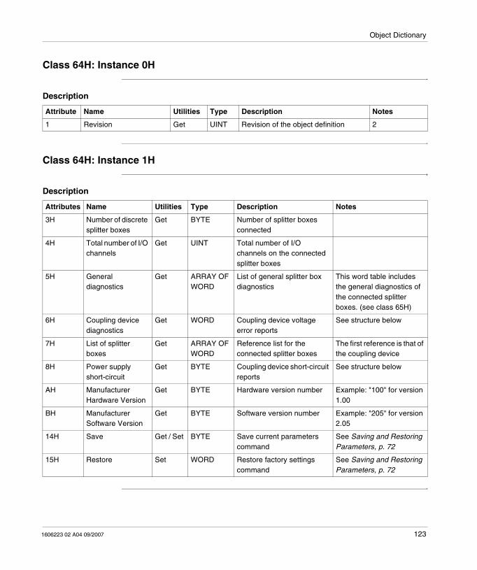
Object Dictionary
1606223 02 A04 09/2007 123
Class 64H: Instance 0H
Description
Class 64H: Instance 1H
Description
Attribute Name Utilities Type Description Notes
1 Revision Get UINT Revision of the object definition 2
Attributes Name Utilities Type Description Notes
3H Number of discrete splitter boxes
Get BYTE Number of splitter boxes connected
4H Total number of I/O channels
Get UINT Total number of I/O channels on the connected splitter boxes
5H General diagnostics
Get ARRAY OF WORD
List of general splitter box diagnostics
This word table includes the general diagnostics of the connected splitter boxes. (see class 65H)
6H Coupling device diagnostics
Get WORD Coupling device voltage error reports
See structure below
7H List of splitter boxes
Get ARRAY OF WORD
Reference list for the connected splitter boxes
The first reference is that of the coupling device
8H Power supply short-circuit
Get BYTE Coupling device short-circuit reports
See structure below
AH Manufacturer Hardware Version
Get BYTE Hardware version number Example: "100" for version 1.00
BH Manufacturer Software Version
Get BYTE Software version number Example: "205" for version 2.05
14H Save Get / Set BYTE Save current parameters command
See Saving and Restoring Parameters, p. 72
15H Restore Set WORD Restore factory settings command
See Saving and Restoring Parameters, p. 72

Object Dictionary
124 1606223 02 A04 09/2007
Attribute 6H This word indicates that there is no voltage or an under-voltage in each of the connectors leaving from the internal bus:
Attribute 8H This byte indicates the short-circuit faults in each of the connectors leaving from the internal bus:
Bit Fault Controller Voltage type
0 Under-voltage Connector 0 Detector (US)
1 Actuator (UA)
2 Connector 1 Detector (US)
3 Actuator (UA)
4 Connector 2 Detector (US)
5 Actuator (UA)
6 Connector 3 Detector (US)
7 Actuator (UA)
8 No voltage Connector 0 Detector (US)
9 Actuator (UA)
10 Connector 1 Detector (US)
11 Actuator (UA)
12 Connector 2 Detector (US)
13 Actuator (UA)
14 Connector 3 Detector (US)
15 Actuator (UA)
Bit Fault Controller Voltage type
0 Short circuit Connector 0 Detector (US)
1 Actuator (UA)
2 Connector 1 Detector (US)
3 Actuator (UA)
4 Connector 2 Detector (US)
5 Actuator (UA)
6 Connector 3 Detector (US)
7 Actuator (UA)

Object Dictionary
1606223 02 A04 09/2007 125
9.9 Class 65H, Splitter Boxes
Presentation
Description This section contains data specific to the splitter boxes.
What's in this Section?
This section contains the following topics:
Topic Page
Class 65H: Instance 0H 126
Class 65H: Instance 1H and the Following Instances 126
Class 65H: 1H and Following Instances, Attributes 3H to 27H 127
Class 65H: 1H and Following Instances, Attributes 28H to 4F of Discrete Splitter Boxes
130
Class 65H: 1H and Following Instances, Attributes 28H to 33H for Analog Splitter Boxes
131
Class 65H: 1H and Following Instances, Attributes 50H to 64H 134

Object Dictionary
126 1606223 02 A04 09/2007
Class 65H: Instance 0H
Description
Class 65H: Instance 1H and the Following Instances
Description The number of instances is governed by the number of splitter boxes. The structure of each instance is as follows:
Attributes Name Utilities Type Description Notes
1 Revision Get UINT Revision of the object definition 1
Attributes Name Utilities Type Description
3H Status Get BYTE Status of the communication on the internal bus
4H Name Get STRING Name of the Coupling Device
5H ID Get WORD Identification number
6H Type Get WORD Device type
7H Manufacturer ID Get WORD Manufacturer identifier
8H Number of connectors Get WORD Number and type of female connectors
9H HW/SW revision Get DWORD � MSB : Software revision number� LSB : Hardware revision number
AH Input data Get ARRAY OF BYTE
Splitter box input bytes
BH Input and diagnostic data
Get ARRAY OF BYTE
Splitter box input and diagnostic bytes
CH Output data Get / Set ARRAY OF BYTE
Splitter box output bytes
DH Diagnostic data Get ARRAY OF BYTE
Splitter box diagnostic bytes
14H ... 1DH Input words Get WORD Input words
1EH ... 27H Output words Get / Set WORD Output words
28H ... 4FH Configuration words Get / Set WORD Configuration words
50H ... 64H Device diagnostics Get WORD Device diagnostics

Object Dictionary
1606223 02 A04 09/2007 127
Class 65H: 1H and Following Instances, Attributes 3H to 27H
Attribute 3H This word indicates that there is no voltage or an under-voltage in each of the connectors leaving from the internal bus:
Attribute 4H at 8H
Attribute 4H presents the splitter box reference as a string of characters and attribute 5H, its identifier.
Attribute 6H gives information on the type of channels available on the splitter box:
� 1 : Discrete inputs� 3 : Discrete inputs and outputs� 4 : Analog inputs� 8 : Analog outputs
Attribute 7H contains the manufacturer's identifier (=1).
Attribute 8H contains the number of connectors available for the I/O-channel connection.
Value Meaning Notes
1H Data exchange Normal operating mode: Communication is established between the splitter box and the coupling device.
80H Initialization Communication initialized at start-up or communication error on the internal bus.
Reference (Attribute 4H)
ID (Attribute 5H) Type (Attribute 6H) Number of connectors (Attribute 8H)
FTM 1DD16C12 56600 3 8* M12
FTM 1DD16C12E 56601 3 8* M12
FTM 1DE16C12 56602 1 8* M12
FTM 1DE16C12E 56603 1 8* M12
FTM 1DD08C12 56610 3 4* M12
FTM 1DD08C12E 56611 3 4* M12
FTM 1DE08C12 56612 1 4* M12
FTM 1DE08C12E 56613 1 4* M12
FTM 1DD08C08 56620 3 8* M8
FTM 1DD08C08E 56621 3 8* M8
FTM 1DE08C08 56622 1 8* M8
FTM 1DE08C08E 56623 1 8* M8
FTM 1AE04C12T 56700 4 4* M12
FTM 1AS04C12T 56710 8 4* M12
FTM 1AS04C12C 56720 8 4* M12
FTM 1AE04C12C 56730 4 4* M12

Object Dictionary
128 1606223 02 A04 09/2007
Attributes AH to DH
These attributes contain different forms of splitter box data. They are used by the "Assembly" object:
Discrete splitter box input data:
� Byte 0: Channels 00 to 07� Byte 1: Channels 10 to 17
Discrete splitter box output data
� Byte 0: Channels 00 to 07� Byte 1: Channels 10 to 17
Analog splitter box input data:
� Bytes 0 & 1: Channel 0� Bytes 2 & 3: Channel 1� Bytes 4 & 5: Channel 2� Bytes 6 & 7: Channel 3
Analog splitter box output data:
� Bytes 0 & 1: Channel 0� Bytes 2 & 3: Channel 1� Bytes 4 & 5: Channel 2� Bytes 6 & 7: Channel 3
Diagnostic data: See the diagnostics chapter.
Reference Input data Diagnostics data Output data
FTM 1DN10 - 4 -
FTM 1DD16C12 2 8 2
FTM 1DD16C12E 2 8 2
FTM 1DE16C12 2 4 -
FTM 1DE16C12E 2 4 -
FTM 1DD08C12 2 8 2
FTM 1DD08C12E 2 8 2
FTM 1DE08C12 2 4 -
FTM 1DE08C12E 2 4 -
FTM 1DD08C08 1 5 1
FTM 1DD08C08E 1 5 1
FTM 1DE08C08 1 3 -
FTM 1DE08C08E 1 3 -
FTM 1AE04C12T 8 5 -
FTM 1AS04C12T - 5 8
FTM 1AS04C12C - 5 8
FTM 1AE04C12C 8 5 -

Object Dictionary
1606223 02 A04 09/2007 129
Attribute 14H at 1DH
These attributes are used to read the input statuses:
Attribute 1EH at 27H
These attributes are used to read the output statuses:
Attributes Discrete splitter box Analog splitter box
14H � Byte 0: Channels 00 to 07� Byte 1: Channels 10 to 17
Channel 0
15H Reserved Channel 1
16H Reserved Channel 2
17H Reserved Channel 3
18H Reserved
Attributes Discrete splitter box Analog splitter box
1EH � Byte 0: Channels 00 to 07� Byte 1: Channels 10 to 17
Channel 0
1FH Reserved Channel 1
20H Reserved Channel 2
21H Reserved Channel 3
22H...27H Reserved

Object Dictionary
130 1606223 02 A04 09/2007
Class 65H: 1H and Following Instances, Attributes 28H to 4F of Discrete Splitter Boxes
Description These attributes are used to configure the discrete splitter boxes.
Discrete Splitter Boxes with M12 connector
Attributes 28H to 2CH are used as indicated in the table below to, with the following rule:
� LSB : Channels 00 to 07� MSB : Channels 10 to 17
Discrete Splitter Boxes with M8 connector
Attributes 28H to 2CH are used as indicated in the table below to, with the following rule:
� LSB : Channels 00 to 07� MSB : Channels 10 to 17
Attributes Function Value Notes
28H Input / Diagnostics � 0 : Input� 1 : Diagnostic (by default)
Only for channels 10 to 17
29H Input / Output � 0 : Input (by default)� 1 : Output
FTM 1DD•• only
2AH Fallback mode � 0 : Fallback (by default)� 1 : Last value maintained
2BH Fallback value � 0 : Output at 0 (by default)� 1 : Output at 1
2CH Polarity � 0 : NO (default)� 1 : NC
Attributes Byte Function Value Notes
40H 0 Fallback mode
� 0 : Fallback (by default)� 1 : Last value maintained
FTM 1DD•• only
1 Input/Output.
� 0 : Input (by default)� 1 : Output
41H 0 Polarity � 0 : NO (default)� 1 : NC
1 Fallback value
� 0 : Output at 0 (by default)� 1 : Output at 1

Object Dictionary
1606223 02 A04 09/2007 131
Class 65H: 1H and Following Instances, Attributes 28H to 33H for Analog Splitter Boxes
Description of Analog Input Splitter Boxes
Attributes 28H to 2CH are used as indicated in the table below:
Attributes Function Description
28H Channel 1 settings See below
29H Channel 2 settings
2AH Channel 3 settings
2BH Channel 4 settings
2CH Additional settings for channel 1 Diagnostics bit [0]� 0: 0 activated (by default)� 1: Disabled
Data format bit [1]� 0 : Motorola format (Most significant - Least significant)� 1 : Intel format (Least significant - Most significant)
Delta bit [2]� 0 : Deactivated (by default)� 1 : Enabled
Other bits Reserved
2DH Additional settings for channel 2
2EH Additional settings for channel 3
2FH Additional settings for channel 4
30H Delta channel 1 The delta value must be between 0 and 32 767.
31H Delta channel 2
32H Delta channel 3
33H Delta channel 4
Note: In order to validate use of the Delta, bit 2 of the corresponding additional configuration word must be at 1.

Object Dictionary
132 1606223 02 A04 09/2007
Setting Analog Input Splitter Box Channels
Attributes 28H to 2BH are used as indicated in the table below:
Attribute value
Scale for FTM 1AE04C12T Scale for FTM 1AE04C12C Filtering
0 or > 8 Channel deactivated -
1 +/- 10V 0...20 mA None
2 0...10 V 4...20 mA
3 +/- 10V 0...20 mA Low
4 0...10 V 4...20 mA
5 +/- 10V 0...20 mA Medium
6 0...10 V 4...20 mA
7 +/- 10V 0...20 mA High
8 0...10 V 4...20 mA

Object Dictionary
1606223 02 A04 09/2007 133
Description of Analog Output Splitter Boxes
Attributes 28H to 2CH are used as indicated in the table below:
Setting Analog Output Splitter Box Channels
Attributes 28H to 2BH are used as indicated in the table below:
Attributes Function Description
28H Channel 1 settings See below
29H Channel 2 settings
2AH Channel 3 settings
2BH Channel 4 settings
2CH Additional settings for channel 1 Diagnostics bit [0]� 0: 0 activated (by default)� 1: Disabled
Data format bit [1]� 0: Motorola format (Most significant - Least significant)� 1: Intel format (Least significant - Most significant)
Fallback mode bit [2]� 0: Last value maintained� 1: Fallback
Other bits Reserved
2DH Additional settings for channel 2
2EH Additional settings for channel 3
2FH Additional settings for channel 4
30H Fallback value The fallback mode value depends on the scale used. It must be between:� -2048 and 2047 for the +/-10 V scale� 0 and 2047 for the other scales
31H Fallback value
32H Fallback value
33H Fallback value
Attribute value
Scale for FTM 1AS04C12T Scale for FTM 1AS04C12C
0 or > 2 Channel deactivated
1 +/- 10V 0...20 mA
2 0...10 V 4...20 mA
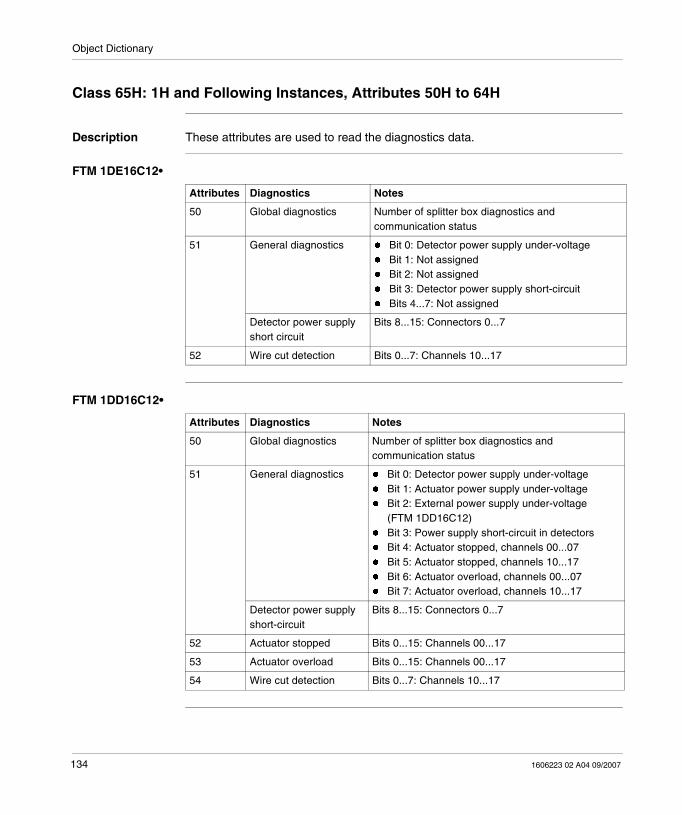
Object Dictionary
134 1606223 02 A04 09/2007
Class 65H: 1H and Following Instances, Attributes 50H to 64H
Description These attributes are used to read the diagnostics data.
FTM 1DE16C12•
FTM 1DD16C12•
Attributes Diagnostics Notes
50 Global diagnostics Number of splitter box diagnostics and communication status
51 General diagnostics � Bit 0: Detector power supply under-voltage� Bit 1: Not assigned� Bit 2: Not assigned� Bit 3: Detector power supply short-circuit� Bits 4...7: Not assigned
Detector power supply short circuit
Bits 8...15: Connectors 0...7
52 Wire cut detection Bits 0...7: Channels 10...17
Attributes Diagnostics Notes
50 Global diagnostics Number of splitter box diagnostics and communication status
51 General diagnostics � Bit 0: Detector power supply under-voltage� Bit 1: Actuator power supply under-voltage� Bit 2: External power supply under-voltage
(FTM 1DD16C12)� Bit 3: Power supply short-circuit in detectors� Bit 4: Actuator stopped, channels 00...07� Bit 5: Actuator stopped, channels 10...17� Bit 6: Actuator overload, channels 00...07� Bit 7: Actuator overload, channels 10...17
Detector power supply short-circuit
Bits 8...15: Connectors 0...7
52 Actuator stopped Bits 0...15: Channels 00...17
53 Actuator overload Bits 0...15: Channels 00...17
54 Wire cut detection Bits 0...7: Channels 10...17

Object Dictionary
1606223 02 A04 09/2007 135
FTM 1DE08C12•
FTM 1DD08C12•
FTM 1DE08C08•
Attributes Diagnostics Notes
50 Global diagnostics Number of splitter box diagnostics and communication status
51 General diagnostics � Bit 0: Detector power supply under-voltage� Bit 1: Not assigned� Bit 2: Not assigned� Bit 3: Detector power supply short-circuit� Bits 4...7: Not assigned
Detector power supply short-circuit
� Bits 8...11: Connectors 0...3� Bits 12...15: Not assigned
52 Wire cut detection Bits 0...3: Channels 10...13
Attributes Diagnostics Notes
50 Global diagnostics Number of splitter box diagnostics and communication status
51 General diagnostics � Bit 0: Detector power supply under-voltage� Bit 1: Power supply under-voltage in actuator� Bit 2: Not assigned� Bit 3: Power supply short-circuit in detectors� Bit 4: Actuator stopped, channels 00...03� Bit 5: Actuator stopped, channels 10...13� Bit 6: Actuator overload, channels 00...03� Bit 7: Actuator overload, channels 10...13
Detector power supply short-circuit
� Bits 8...11: Connectors 0...3� Bits 12...15: Not assigned
52 Actuator stopped Bits 0...15: Channels 00...13
53 Actuator overload Bits 0...15: Channels 00...13
54 Wire cut detection Bits 0...3: Channels 10...13
Attributes Diagnostics Notes
50 Global diagnostics Number of splitter box diagnostics and communication status
51 General diagnostics � Bit 0: Detector power supply under-voltage� Bits 1 and 2 Not assigned� Bit 3: Power supply short-circuit in detectors� Bits 4...7: Not assigned
Detector power supply short-circuit
Bits 8...15: Connectors 0...7

Object Dictionary
136 1606223 02 A04 09/2007
FTM 1DD08C08•
FTM 1AE04C12T
Attributes Diagnostics Notes
50 Global diagnostics Number of splitter box diagnostics and communication status
51 General diagnostics � Bit 0: Detector power supply under-voltage� Bit 1: Power supply under-voltage in actuator� Bit 2: Not assigned� Bit 3: Power supply short-circuit in detectors� Bit 4: Actuator stopped, channels 00...07� Bit 5: Not assigned� Bit 6: Actuator overload, channels 00...07� Bit 7: Not assigned
Detector power supply short-circuit
Bits 8...15: Connectors 0...7
52 Actuator stopped Bits 0...7: Channels 00...07
Actuator overload Bits 8...15: Channels 00...07
Attributes Diagnostics Notes
50 General diagnostics � Bit 0: Detector power supply under-voltage� Bit 3: 24 V detector power supply short-circuit (pin 1)� Bit 6: Scale overshoot (less, +/- 10 V only)� Bit 7: Scale overshoot (greater)
51 Channel 0 (LSB) � Bits 2 and 10 Scale overshoot (greater)� Bits 3 and 11 Scale overshoot (less, +/- 10 V only)� Bits 4 and 12 24 V detector power supply short-circuit
(pin 1)
Channel 1 (MSB)
52 Channel 2 (LSB)
Channel 3 (MSB)

Object Dictionary
1606223 02 A04 09/2007 137
FTM1AE04C12C
FTM1AS04C12T
FTM 1AS04C12C
Attributes Diagnostics Notes
50 General diagnostics � Bit 0: Detector power supply under-voltage� Bit 3: 24 V detector power supply short-circuit (pin 1)� Bit 5: Cable breakage� Bit 6: Scale overshoot (less, +/- 10 V only)� Bit 7: Scale overshoot (greater)
51 Channel 0 (LSB) � Bits 0 and 8 Cable breakage� Bits 2 and 10 Scale overshoot (greater)� Bits 3 and 11 Scale overshoot (less, +/- 10 V only)� Bits 4 and 12 24 V detector power supply short-
circuit (pin 1)
Channel 1 (MSB)
52 Channel 2 (LSB)
Channel 3 (MSB)
Attributes Diagnostics Notes
50 General diagnostics � Bit 0: Detector power supply under-voltage� Bit 1: Actuator power supply under-voltage� Bit 2: Power cut in actuators� Bit 3: 24 V detector power supply short-circuit (pin 1)� Bit 4: Setpoint value deactivated
51 Channel 0 (LSB) � Bits 1 and 9 Setpoint value deactivated � Bits 4 and 12 24 V detector power supply short-
circuit (pin 1)Channel 1 (MSB)
52 Channel 2 (LSB)
Channel 3 (MSB)
Attributes Diagnostics Notes
50 General diagnostics � Bit 0: Detector power supply under-voltage� Bit 1: Actuator power supply under-voltage� Bit 2: Power cut in actuators� Bit 3: 24 V detector power supply short-circuit (pin 1)� Bit 5: Cable breakage
51 Channel 0 (LSB) � Bits 0 and 8 Cable breakage� Bits 4 and 12 24 V detector power supply short-
circuit (pin 1)Channel 1 (MSB)
52 Channel 2 (LSB)
Channel 3 (MSB)

Object Dictionary
138 1606223 02 A04 09/2007

1606223 02 A04 09/2007 139
Glossary
Analog Input A module containing circuits that enable analog dc (direct current) input signals to be converted into discrete values that can be handled by the processor. This implies that the analog inputs are generally direct values — in other words: a value in the data table is a direct reflection of the analog signal value.
Analog output A module containing circuits that transmit an analog dc (direct current) input signal proportional to a discrete input value to the processor module. This implies that the analog outputs are generally direct values — in other words: a value in the data table directly governs the analog signal value.
Configuration The arrangement and connections made between the hardware components of a system, as well as the selected hardware and software options that determine the system's operating characteristics.
DESINA Standard relating to the connector technology of sensors and actuators, established by a German association of machine manufacturers.
A
C
D

Glossary
140 1606223 02 A04 09/2007
DeviceNet, protocol
DeviceNet is a network based on low level connections and established over CAN, using a serial bus system without a defined application layer. Consequently, DeviceNet defines a layer for the industrial application of the CAN protocol.
Differential input An input design in which two wires (+ and -) run from each signal source to the data acquisition interface. The voltage between the input and the interface ground is measured by two high-impedance amplifiers, and the outputs of the two amplifiers are subtracted by a third amplifier to give the difference between the + and - inputs. The voltage common to the two wires is thus eliminated. A differential design eliminates the problem of ground differences encountered with single end connections. It also minimizes the problem of noise interference between channels.
Discrete input/output
Another expression used is discrete input/output. Designates an input or output featuring an individual circuit connection to the module corresponding directly to a bit or word of the data table storing the value of the signal on this I/O circuit. A discrete I/O gives the control logic discrete access to I/O values.
Dup Mac Duplicate MAC ID. Network startup test used to check if any DeviceNet equipment is using the same MAC ID address.
EDS Electronic Data Sheet. The EDS is a file in standard ASCII format containing information on a communication functionality of a network device and the content of its object dictionary. The EDS also defines device-specific and manufacturer-specific objects.
Electro-magnetic interference
Electro-magnetic interferences (EMI) are liable to cause interruptions, anomalies or disturbances in the performance of electronic hardware. It occurs when a source electronically transmits a signal that interferes with other devices.
EMC Electro-Magnetic Compatibility. Devices that comply with EMC requirements are capable of error-free operation within the specified electro-magnetic limits of the system.
Fallback mode A secure mode to which any I/O module can revert should the communication connection fail.
E
F

Glossary
1606223 02 A04 09/2007 141
Fallback value The value adopted by a device when it enters the fallback mode. Generally, the fallback value is either configured, or is the device's last stored value.
I/O module In a programmable control system, an I/O module communicates directly with sensors or actuators used in the machine or process. This module is the component that is installed in the I/O connection base and establishes the electrical connections between the controller and the fieldbuses. The functionalities common to all I/O modules are offered in a range of signal capacities and levels.
IEC International Electrotechnical Commission. Commission officially founded in 1906 and devoted to the advancement of theory and practice in the following sciences: electrical engineering, electronic engineering, information technology and computer engineering. The IEC 1131 standard covers industrial automation equipment.
IEC type 1 input Type 1 discrete inputs support sensor signals from mechanical switching devices such as relay contacts and push-buttons operating under normal climatic conditions.
IEC type 1+ input Type 1+ discrete inputs support sensor signals from mechanical switching devices such as relay contacts and push-buttons (under normal to moderate climatic conditions), three-wire proximity switches and two-wire proximity switches with the following characteristics:� A voltage drop of less than or equal to 8 V� A minimum operating current capacity of less than or equal to 2 mA� A maximum current in blocked state of less than or equal to 0.8 mA
IEC type 2 input Type 2 discrete inputs support sensor signals from solid-state devices and mechanical switching devices such as relay contacts, push-buttons (under normal to rigorous climatic conditions), and two or three-wire proximity switches.
IEEE Institute of Electrical and Electronics Engineers, Inc. An international association for the standardization and evaluation of compliance in all areas of electro-technology, including electricity and electronics.
Input filter The period for which a sensor must keep its signal activated/deactivated before the input module detects a change of state.
I

Glossary
142 1606223 02 A04 09/2007
Input polarity The polarity of an input channel determines when the input module sends a 1 (one) and when it sends a 0 (zero) to the master controller. If the polarity is normal, an input channel will send a 1 (one) to the controller as soon as its fieldbus sensor is activated. If the polarity is reversed, an input channel will send a 0 (zero) to the controller as soon as its fieldbus sensor is activated.
Input response time
The time required for an input channel to receive a signal from a fieldbus sensor and pass it on to the island bus.
LSB Least Significant Byte. The part of a number, address or field that is written as the value furthest to the right in conventional hexadecimal or binary notation.
LSb Least Significant Bit. The part of a number, address or field that is written as the value furthest to the right in conventional hexadecimal or binary notation.
Master/slave model
In a network using a master/slave model, the direction of control is always from the master to slave devices.
MSB Most Significant Byte. The part of a number, address or field that is written as the value furthest to the left in conventional hexadecimal or binary notation.
MSb Most Significant Bit. The part of a number, address or field that is written as the value furthest to the left in conventional hexadecimal or binary notation.
N.C. contact Designates a normally closed contact. Also called break contacts. A pair of relay contacts that is closed when the relay coil is low and open when it is energized.
N.O. contact Normally open contact Also called make contacts. A pair of relay contacts that is open when the relay coil is low and closed when it is energized.
Object Dictionary
Sometimes referred to as the "object directory", this element of the DeviceNet device model provides the plan for the internal structure of DeviceNet devices. The object dictionary of a given device is a conversion table describing the data types, the communication objects and the application objects used by the device. By accessing the object dictionary structure of a specific device via the DeviceNet fieldbus, you can anticipate its network behavior enabling you to design a distributed application in which it can be implemented.
L

Glossary
1606223 02 A04 09/2007 143
Output polarity The polarity of an output channel determines when the output module activates its fieldbus actuator and when it deactivates it. If the polarity is normal, an output channel will activate its actuator as soon as the master controller sends it the value 1. If the polarity is reversed, an output channel will activate its actuator as soon as the master controller sends it the value 0.
Output response time
The time it takes for an output module to receive an output signal from the island bus and transmit it to its fieldbus actuator.
PE Protective Earth in English, Ground.
Peer In English: PLC or Programmable Logic Controller. The PLC is the nerve center of the industrial manufacturing process. Such a device is said to "automate a process", in contrast to a relay control system. These PLCs are in fact simply computers designed to survive under the sometimes harsh conditions of an industrial environment.
Reverse polarity protection
In a circuit, use of a diode to protect against damage and any inadvertent operations that may be caused if the polarity of the applied power is accidentally reversed.
Sink load (or positive logic load)
Designates an output which, when activated, receives DC current from its load.
Telegram A data packet used in serial communications.

Glossary
144 1606223 02 A04 09/2007

CBA
1606223 02 A04 09/2007 145
CCharacteristics
Inputs, 46of its Environment, 38Outputs, 49Splitter box, 49
DDiagnostics
Analog I/O, 99Discrete I/O, 98Internal bus, 97Power supply, 94
EEMC Compatibility, 31
FField Bus Status Diagnostics, 96
GGround Electrode
Connection, 29Position, 29
IInternal Bus
Connection, 43Terminator, 44Wiring Diagram, 43
MM12 Connector
Pin Assignment for Actuators and Sensors, 47, 50
M12 ConnectorsField Bus Pin Assignment, 55
M8 ConnectorAssignment of pins for actuators and sensors, 48
Master, 142
NN, 142Node-ID
Configuration, 59
OObject, 143
PPE, 143
Index

Index
146 1606223 02 A04 09/2007
Properties, 38Input, 49outputs, 46Splitter box, 46
RReverse, 143
SSink, 143
TTelegram, 143Transmission Speed
Configuration, 59