advancing design - processing · pdf filetable of contents slipstick conveyor trough the...
TRANSCRIPT
ADVANCINGDESIGN
IN HORIZONTAL MOTION CONVEYING SYSTEMS

ABOUT THE SLIPSTICK®.The most productive advancement in horizontal conveying
equipment in decades, the Slipstick® horizontal motion
conveyor is recognized for its gentle, non-impact conveying
motion and high reliability performance.
Featuring a slow-forward, quick-return conveying motion,
The Slipstick is unrivaled in maintaining product quality
in a variety of applications. Unlike conventional vibrating
conveyors, the Slipstick won’t compromise product qual-
ity whether it’s utilized in food processing plants or bulk
product manufacturing.
The Slipstick can also operate at multiple speeds and in
reverse, while many vibrating conveyors are confined to
one-speed and one-direction. The Slipstick conveyor is
ideal for food products, pharmaceuticals, heavy loads,
fragile products, abrasive products, powders and other
bulk products.
Conveying Potential Drive Systems
Trough Cover TubeConveyor
Support &Suspension
ScreensWho is
Triple/S DynamicsIndustry
Applications
Inlets/Outlets
Trough
Gates
X Force
HOW TO USE THIS GUIDEClick on the topic you’d like more information about from
the selection of buttons to your right. On each page,
simply click the arrows to move backwards or forwards.
1-09 Published by Triple/S ©2009
CustomizedQuote
EngineeringDrawings
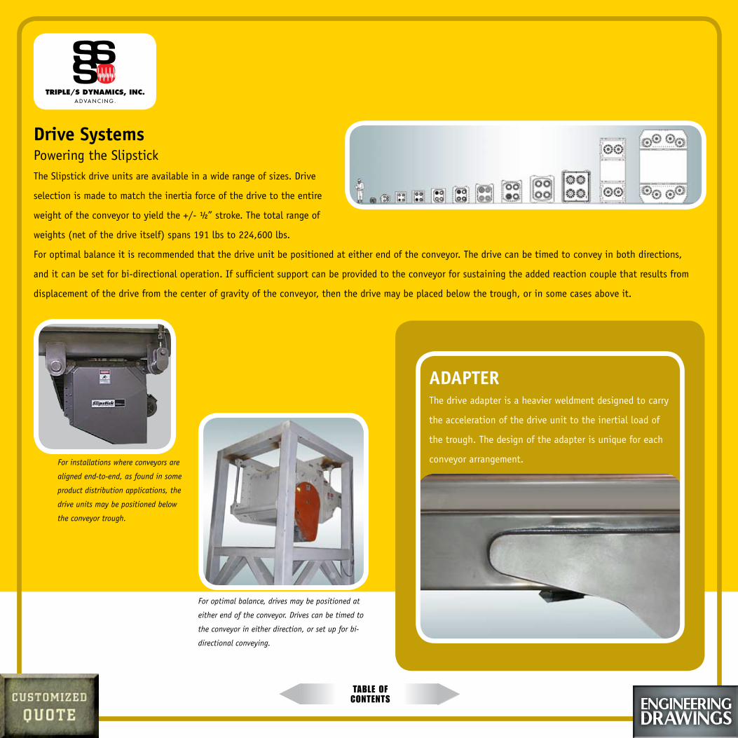
Table of conTenTs
Drive Systems Powering the SlipstickThe Slipstick drive units are available in a wide range of sizes. Drive
selection is made to match the inertia force of the drive to the entire
weight of the conveyor to yield the +/- ½” stroke. The total range of
weights (net of the drive itself) spans 191 lbs to 224,600 lbs.
For optimal balance it is recommended that the drive unit be positioned at either end of the conveyor. The drive can be timed to convey in both directions,
and it can be set for bi-directional operation. If sufficient support can be provided to the conveyor for sustaining the added reaction couple that results from
displacement of the drive from the center of gravity of the conveyor, then the drive may be placed below the trough, or in some cases above it.
ADAPTERThe drive adapter is a heavier weldment designed to carry
the acceleration of the drive unit to the inertial load of
the trough. The design of the adapter is unique for each
conveyor arrangement.
For optimal balance, drives may be positioned at
either end of the conveyor. Drives can be timed to
the conveyor in either direction, or set up for bi-
directional conveying.
For installations where conveyors are
aligned end-to-end, as found in some
product distribution applications, the
drive units may be positioned below
the conveyor trough.

Table of conTenTs
Slipstick Conveyor TroughThe conveyor trough is usually provided as formed steel and can be provided in almost
any cross sections that can be formed.
The majority of the designs are of a rectangular cross section. A number of standards
have been adopted to reduce the design time required as well as to reduce the amount
of other parts associated with the manufacture of troughs.
For light duty conveyors a standard depth is eight inches and widths are kept at
intervals of six inches.
Travel RatesWith the travel rate of most dry, free-flowing materials falling in the 25-30 feet/ minute
range, the bed depth can be calculated for the product flow for any width.
Triple/S Dynamics offers a flow calculator specifically for this application.
The maximum recommended depth is highly dependent on the product characteristics.
Materials with a low angle of repose will not convey evenly in deep beds. Materials that
mechanically interlock may be conveyed at much deeper beds levels (up to eight feet).
For difficult materials a conveying test can be arranged for demonstration and
verification of anticipated material travel rates.
However a common standard depth is between three and five inches for most dry,
free-flowing materials, in a trough depth of eight inches.
Construction Materials
The trough is most commonly provided in steel, either stainless for sanitary conveyors, or mild steel.
Some applications call for the use of alternate materials of construction, or for product contact, such
as titanium, polyethylene plastic, refractory ceramics, rubber, aluminum, and other materials. Conveyor
troughs may be supplied as single or multiple channels.
The Sliptsick conveyor
trough may be equipped
with a variety of discharge
gates, pneumatically
actuated product
retainers, screens,
and other devices.
Conveyor lengths to 250
feet are possible.
Conveyor troughs can be provided with
multiple channels for handling different
products in a single conveyor.

Table of conTenTs
Trough CoversThe trough may be open-topped, or enclosed with covers. Integral
covers may be clamped, hinged and clamped, bolted, or welded in
place. Access ports and viewports may be specified. Stationary covers
may also be employed with external supports.
Sanitary, dust-tight inlets and access ports are available. Sanitary integral
pan covers are a common feature for providing cleanliness of operation and
food safety.

Table of conTenTs
Tube ConveyorFor applications where access to the interior of the trough is to be restricted, the trough may be specified as a sealed tube section. Round sections have
been provided as well as rectangular sections.
A rectangular section is a more space-effective design than a round section as the
volume of conveyed material in a round section is much less than a
rectangular cross section for a given bed depth.
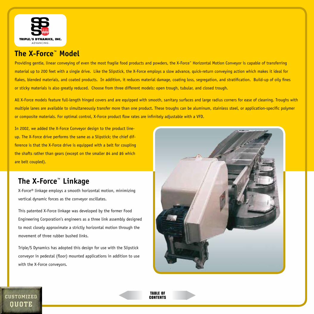
Table of conTenTs
The X-Force™ Model Providing gentle, linear conveying of even the most fragile food products and powders, the X-Force™ Horizontal Motion Conveyor is capable of transferring
material up to 200 feet with a single drive. Like the Slipstick, the X-Force employs a slow advance, quick-return conveying action which makes it ideal for
flakes, blended materials, and coated products. In addition, it reduces material damage, coating loss, segregation, and stratification. Build-up of oily fines
or sticky materials is also greatly reduced. Choose from three different models: open trough, tubular, and closed trough.
All X-Force models feature full-length hinged covers and are equipped with smooth, sanitary surfaces and large radius corners for ease of cleaning. Troughs with
multiple lanes are available to simultaneously transfer more than one product. These troughs can be aluminum, stainless steel, or application-specific polymer
or composite materials. For optimal control, X-Force product flow rates are infinitely adjustable with a VFD.
In 2002, we added the X-Force Conveyor design to the product line-
up. The X-Force drive performs the same as a Slipstick; the chief dif-
ference is that the X-Force drive is equipped with a belt for coupling
the shafts rather than gears (except on the smaller #4 and #6 which
are belt coupled).
The X-Force™ Linkage X-Force® linkage employs a smooth horizontal motion, minimizing
vertical dynamic forces as the conveyor oscillates.
This patented X-Force linkage was developed by the former Food
Engineering Corporation’s engineers as a three link assembly designed
to most closely approximate a strictly horizontal motion through the
movement of three rubber bushed links.
Triple/S Dynamics has adopted this design for use with the Slipstick
conveyor in pedestal (floor) mounted applications in addition to use
with the X-Force conveyors.
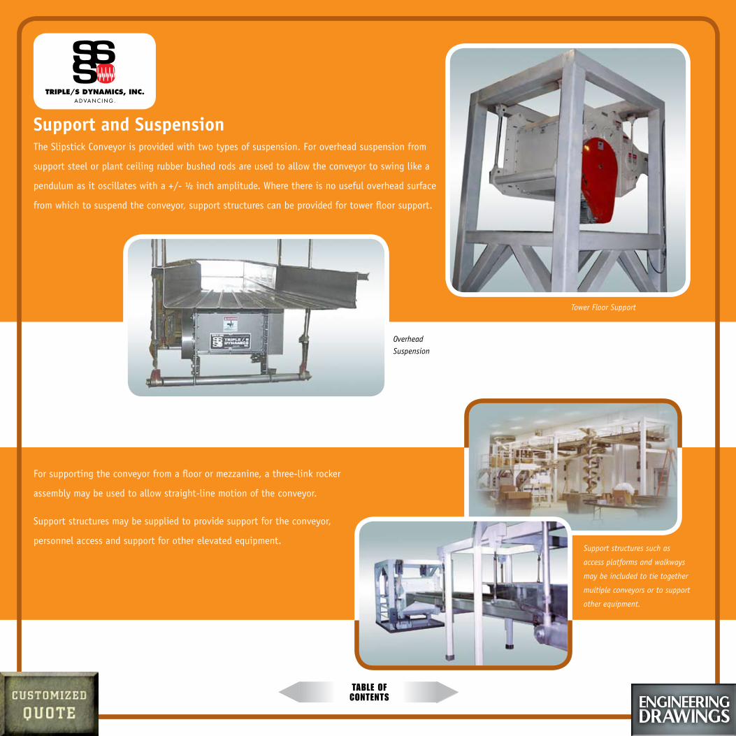
Table of conTenTs
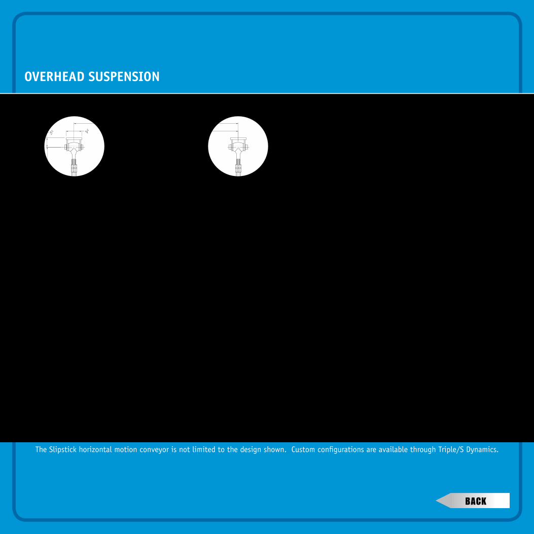
Support and SuspensionThe Slipstick Conveyor is provided with two types of suspension. For overhead suspension from
support steel or plant ceiling rubber bushed rods are used to allow the conveyor to swing like a
pendulum as it oscillates with a +/- ½ inch amplitude. Where there is no useful overhead surface
from which to suspend the conveyor, support structures can be provided for tower floor support.
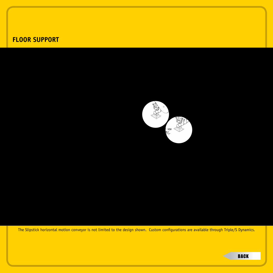
For supporting the conveyor from a floor or mezzanine, a three-link rocker
assembly may be used to allow straight-line motion of the conveyor.
Support structures may be supplied to provide support for the conveyor,
personnel access and support for other elevated equipment.
Tower Floor Support
Overhead Suspension
Support structures such as
access platforms and walkways
may be included to tie together
multiple conveyors or to support
other equipment.

Inlets/OutletsInlets and outlets may be installed anywhere along the length
of the trough. They may be open or sealed with flexible boots.
Dust pick-ups may be installed for extraction of any airborne dust
created at material transfer points (the horizontal motion of the
Slipstick itself does not create dusting).
Table of conTenTs
The Conical Discharge is used for the even distribution
of product onto a multiple head weigh scale.
Sealed inlets and outlets may be used for dusty products.
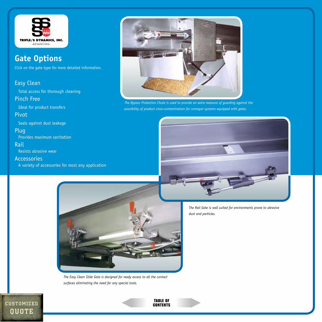
Table of conTenTs
Gate OptionsClick on the gate type for more detailed information.
Easy Clean Total access for thorough cleaning
Pinch Free Ideal for product transfers
Pivot Seals against dust leakage
Plug Provides maximum sanitation
Rail Resists abrasive wear
Accessories A variety of accessories for most any application
The Bypass Protection Chute is used to provide an extra measure of guarding against the
possibility of product cross-contamination for conveyor systems equipped with gates.
The Easy Clean Slide Gate is designed for ready access to all the contact
surfaces eliminating the need for any special tools.
The Rail Gate is well suited for environments prone to abrasive
dust and particles.
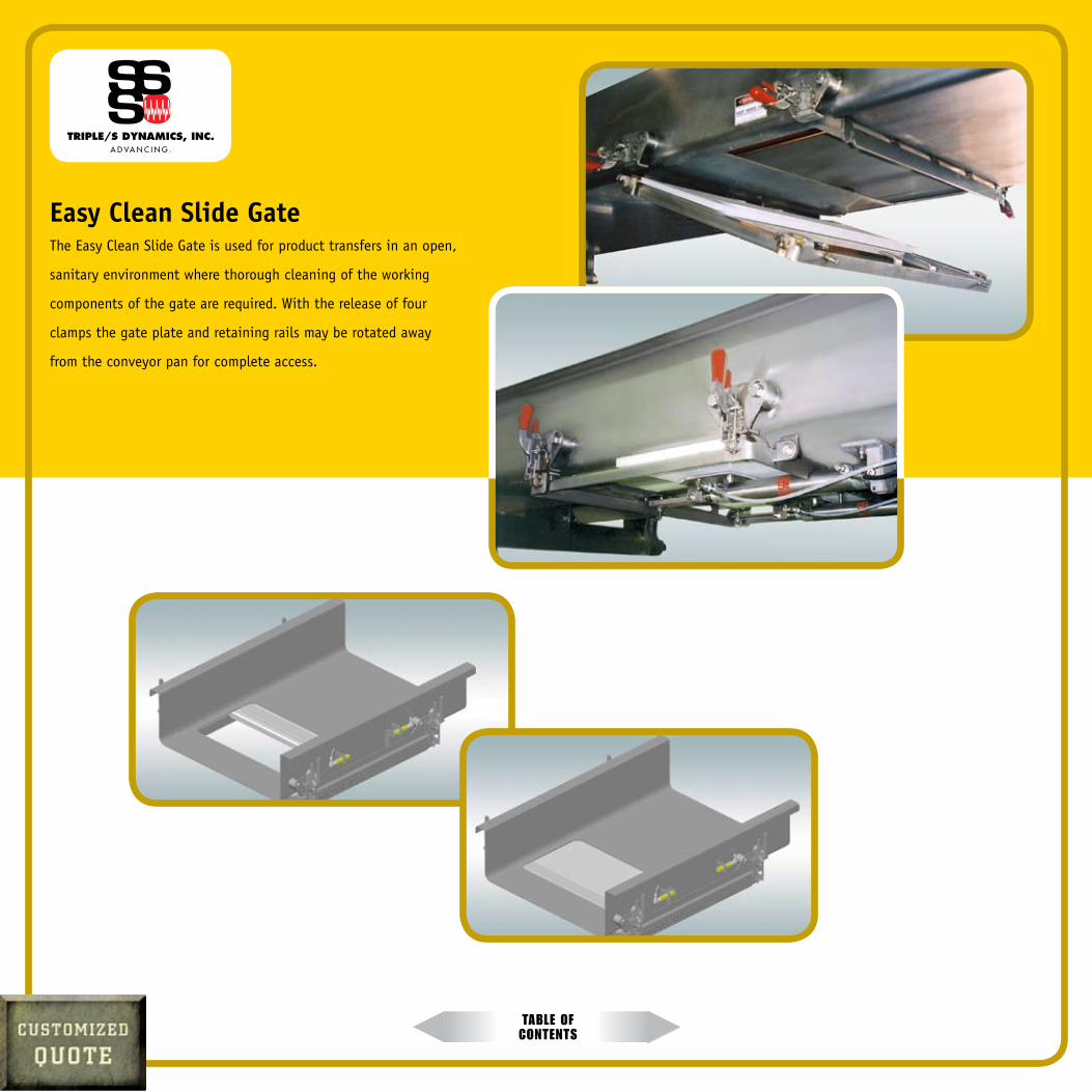
Table of conTenTs
Easy Clean Slide Gate The Easy Clean Slide Gate is used for product transfers in an open,
sanitary environment where thorough cleaning of the working
components of the gate are required. With the release of four
clamps the gate plate and retaining rails may be rotated away
from the conveyor pan for complete access.

Table of conTenTs
Pinch Free GateThe Pinch Free Gate is installed at the end of a conveyor pan and does not close
against a contacting edge or surface. This gate is used in product transfers to an-
other conveyor, as in a modular distribution system, or to another piece of
equipment. It is also used in applications where product damage due to gate
closure is a potential issue.
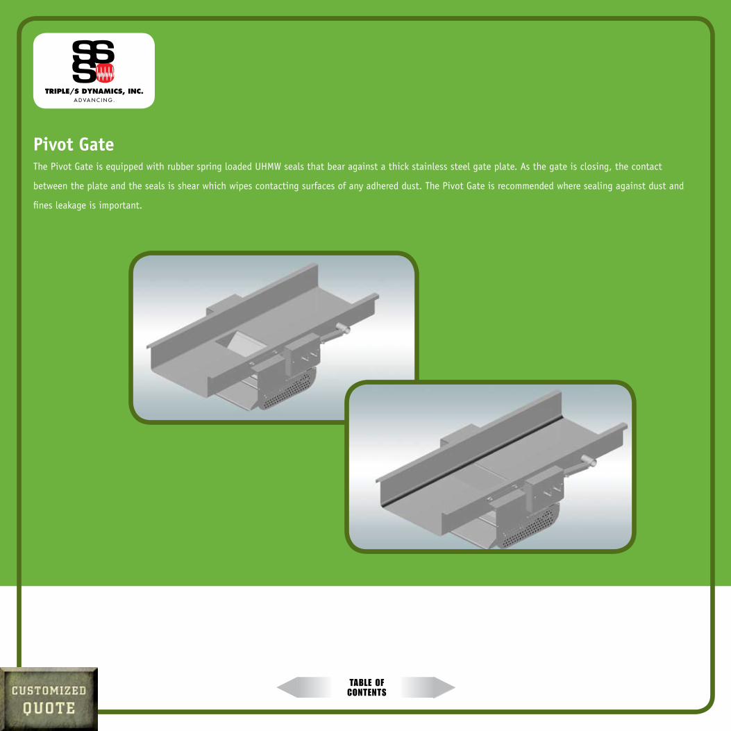
Table of conTenTs
Pivot GateThe Pivot Gate is equipped with rubber spring loaded UHMW seals that bear against a thick stainless steel gate plate. As the gate is closing, the contact
between the plate and the seals is shear which wipes contacting surfaces of any adhered dust. The Pivot Gate is recommended where sealing against dust and
fines leakage is important.

Table of conTenTs
Plug GateThe Plug Gate is used where maximum sanitation
is required. The working components are all
stainless steel, and there are no seals. This gate
meets USDA and 3A standards for sanitary design.
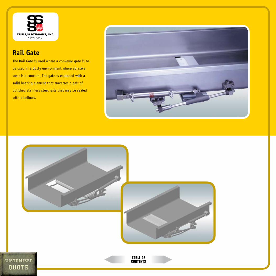
Table of conTenTs
Rail GateThe Rail Gate is used where a conveyor gate is to
be used in a dusty environment where abrasive
wear is a concern. The gate is equipped with a
solid bearing element that traverses a pair of
polished stainless steel rails that may be sealed
with a bellows.

Table of conTenTs
Gate AccessoriesThe Bypass Protection Chute is used under gates where improved
protection against the possibility of a cross-contamination from a gate fault
must be minimized. It is simply a two-way diverter that may be pneumatically
or manually actuated.
The Flow Arrestor is often used to temporarily stop product flow when a
gate immediately downstream is closed. This prevents product from being
damaged in the gate closure. The Flow Arrestor may also be used to build
surge capacity in the Slipstick Conveyor. For fragile products the Flow Arrestor
offers a stationary mounting which is more gentle with the product.
Remotely actuated gates on Slipstick Conveyors are pneumatically powered.
Most gates are fit with a proprietary pneumatic cylinder that
includes a stainless steel body and aluminum end fittings.
All-stainless cylinders are also available.
The cylinders are equipped with flow control valves on each
port for speed control of the gate actuation. Pneumatic tubing
is not usually supplied as the pneumatic lines are run after the
conveyor is installed.
Gates may also be specified with proximity sensors for
position sensing. This may be a pair of simple reed switches
mounted to the cylinder body to detect the position of a
magnetized piston, or Hall Effect proximity sensors may be
installed to detect the position of a gate component.
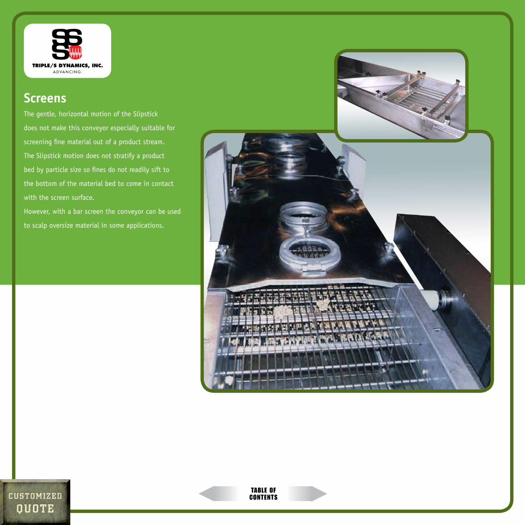
Table of conTenTs
ScreensThe gentle, horizontal motion of the Slipstick
does not make this conveyor especially suitable for
screening fine material out of a product stream.
The Slipstick motion does not stratify a product
bed by particle size so fines do not readily sift to
the bottom of the material bed to come in contact
with the screen surface.
However, with a bar screen the conveyor can be used
to scalp oversize material in some applications.

Table of conTenTs
Industry ApplicationsFood Handling
Triple/S Dynamics offers the highest performing conveying and distribution systems in the food industry. No matter which system or solution is right for your
particular requirements, you can count on Triple/S to provide a gentle conveying motion that helps eliminate product damage. Discourages build-up of materials
on the conveying surface. And significantly improves sanitation. With thousands of Triple/S conveyors at work in North America, Europe, and the Far East, it’s
clear that Triple/S has set the new standard of product quality and sanitation.
Dry Bulk Wealth of knowledge and full range of equipment combines to make our solutions ideal for applications where products are dusty, friable, hazardous, sticky,
abrasive, or in instances where products require special sanitation provisions. Ultimately, our primary objective is to offer the best balance of product yield,
product purity, capital cost, and simplicity of operation to match the needs of most any application. And to meet the requirements of even the most discerning
customer.
Recycling
Triple/S Dynamics offers one of the broadest ranges of recycling and waste handling systems and
equipment in the industry. With a goal of building equipment for consistent reliability and low
maintenance, we engineer and manufacture durable, high-performance chopping and granulating
equipment, separation equipment, and for material movement, ultra-efficient conveyors.
For applications demanding a specialized solution, Triple/S can custom engineer a turnkey,
integrated system designed to fit your specific needs.
Table of conTenTs
ABOUT TRIPLE/S DYNAMICS
With installations around the world, Triple/S Dynamics is recognized as one of the leading conveyor manufacturers of horizontal motion conveyor systems and
screening and separation equipment for a variety of processing industries.
Throughout more than 100 years of service, Triple/S has accumulated a depth and breadth of experience that has led to the most rugged, safe, sanitary, and reli-
able horizontal motion conveyor systems in the industry. We take pride in tailoring solutions to meet the specific needs of each customer, providing the best,
most precise match of equipment to application. Industries we serve include mining, food processing, recycling, bulk handling, agriculture, chemical processing,
and foundry.
With a rich history of innovation, Triple/S Dynamics remains a pioneer in advancing the entire processing industry. Our decades of experience, wealth of indus-
try-specific knowledge, and focus on the total solution rather than just the equipment, means we can offer the most comprehensive, flexible, and cost efficient
recycling or waste handling system to match your application.
The three “S’s” of Triple/S Dynamics represent the names of brothers Edwin
and Walter Steele and Henry Sutton who founded the company in 1888.
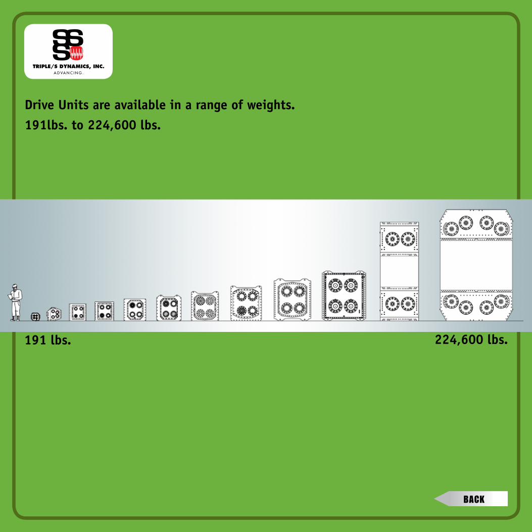
Drive Units are available in a range of weights.191lbs. to 224,600 lbs.
191 lbs. 224,600 lbs.
bacK

The Slipstick horizontal motion conveyor is not limited to the design shown. Custom configurations are available through Triple/S Dynamics.
END PLACEMENT
bacK

The Slipstick horizontal motion conveyor is not limited to the design shown. Custom configurations are available through Triple/S Dynamics.
BOTTOM PLACEMENT
bacK
The Slipstick horizontal motion conveyor is not limited to the design shown. Custom configurations are available through Triple/S Dynamics.
OVERHEAD SUSPENSION
bacK
The Slipstick horizontal motion conveyor is not limited to the design shown. Custom configurations are available through Triple/S Dynamics.
FLOOR SUPPORT
bacK
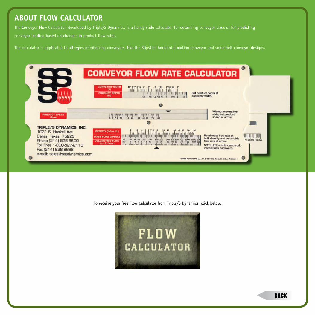
To receive your free Flow Calculator from Triple/S Dynamics, click below.
ABOUT FLOw CALCULATOR
The Conveyor Flow Calculator, developed by Triple/S Dynamics, is a handy slide calculator for determing conveyor sizes or for predicting
conveyor loading based on changes in product flow rates.
The calculator is applicable to all types of vibrating conveyors, like the Slipstick horizontal motion conveyor and some belt conveyor designs.
bacK