advances in membrane technologies
TRANSCRIPT

Advances in Membrane Technologies
Edited by Amira Abdelrasoul
Edited by Amira Abdelrasoul
Membrane technologies are currently the most effective and sustainable methods utilized in diversified water filtration, wastewater treatment, as well as industrial and sustainable energy applications. This book covers essential subsections of membrane separation and bioseparation processes from the perspectives of technical innovation,
novelty, and sustainability. The book offers a comprehensive overview of the latest improvements and concerns with respect to membrane fouling remediation techniques,
issues of bioincompatibility for biomedical applications, and various subareas of membrane separation processes, which will be an efficient resource for engineers.
Published in London, UK
© 2020 IntechOpen © Victoriia Paliy / iStock
ISBN 978-1-78984-806-9
Advances in M
embrane Technologies


Advances in Membrane Technologies
Edited by Amira Abdelrasoul
Published in London, United Kingdom


Supporting open minds since 2005
Advances in Membrane Technologieshttp://dx.doi.org/10.5772/intechopen.82587Edited by Amira Abdelrasoul
Assistant to the Editor(s): Arash Mollahosseini
ContributorsAmira Abdelrasoul, Huu Doan, Ahmad Rahimpour, Mohammad Reza Shirzad Kebria, Shubham Lanjewar, Anirban Roy, Anupam Mukherjee, Lubna Muzamilrehman, Chil-Hung Cheng, Katrina Jose, Fadi Layyous Gedeon, Yaghoub Mansourpanah, Farideh Emamian, Mohammad Mahdi A. Shirazi, Saeed Bazgir, Fereshteh Meshkani, Maryam Amini, Eltayeb Mohamedelhassan, Baoqiang Liao, Arash Mollahosseini, Ahmed Shoker
© The Editor(s) and the Author(s) 2020The rights of the editor(s) and the author(s) have been asserted in accordance with the Copyright, Designs and Patents Act 1988. All rights to the book as a whole are reserved by INTECHOPEN LIMITED. The book as a whole (compilation) cannot be reproduced, distributed or used for commercial or non-commercial purposes without INTECHOPEN LIMITED’s written permission. Enquiries concerning the use of the book should be directed to INTECHOPEN LIMITED rights and permissions department ([email protected]).Violations are liable to prosecution under the governing Copyright Law.
Individual chapters of this publication are distributed under the terms of the Creative Commons Attribution - NonCommercial 4.0 International which permits use, distribution and reproduction of the individual chapters for non-commercial purposes, provided the original author(s) and source publication are appropriately acknowledged. More details and guidelines concerning content reuse and adaptation can be found at http://www.intechopen.com/copyright-policy.html.
NoticeStatements and opinions expressed in the chapters are these of the individual contributors and not necessarily those of the editors or publisher. No responsibility is accepted for the accuracy of information contained in the published chapters. The publisher assumes no responsibility for any damage or injury to persons or property arising out of the use of any materials, instructions, methods or ideas contained in the book.
First published in London, United Kingdom, 2020 by IntechOpenIntechOpen is the global imprint of INTECHOPEN LIMITED, registered in England and Wales, registration number: 11086078, 7th floor, 10 Lower Thames Street, London, EC3R 6AF, United KingdomPrinted in Croatia
British Library Cataloguing-in-Publication DataA catalogue record for this book is available from the British Library
Additional hard and PDF copies can be obtained from [email protected]
Advances in Membrane TechnologiesEdited by Amira Abdelrasoulp. cm.Print ISBN 978-1-78984-806-9Online ISBN 978-1-78984-807-6eBook (PDF) ISBN 978-1-78985-864-8
An electronic version of this book is freely available, thanks to the support of libraries working with Knowledge Unlatched. KU is a collaborative initiative designed to make high quality books Open Access for the public good. More information about the initiative and links to the Open Access version can be found at www.knowledgeunlatched.org

Selection of our books indexed in the Book Citation Index in Web of Science™ Core Collection (BKCI)
Interested in publishing with us? Contact [email protected]
Numbers displayed above are based on latest data collected. For more information visit www.intechopen.com
4,600+ Open access books available
151Countries delivered to
12.2%Contributors from top 500 universities
Our authors are among the
Top 1%most cited scientists
120,000+International authors and editors
135M+ Downloads
We are IntechOpen,the world’s leading publisher of
Open Access booksBuilt by scientists, for scientists


Meet the editor
Dr. Amira Abdelrasoul, P Eng, is an assistant professor in the Chemical and Biological Engineering Department and Division of Biomedical Engineering at the University of Saskatchewan. Prior to joining the University of Saskatchewan in 2017, she was a lecturer and postdoctoral research associate in the Depart-ment of Chemical Engineering at Ryerson University in Toronto, Ontario. Dr. Abdelrasoul received her PhD degree in Chemical
Engineering in 2015 from Ryerson University with the Governor General Academ-ic Gold Medal and the C. Ravi Ravindran Outstanding Doctoral. Dr. Abdelrasoul is Principal Investigator of the Membrane Science and Nanotechnology Research Center at the University of Saskatchewan where she leads her research group on ad-vanced membrane science and nanotechnology for energy and water sustainability and biomedical applications; biomimetic nanomaterials for advanced technologies; and process modeling, simulation, and optimization of complex systems.

Contents
Preface III
Chapter 1 1Introductory Chapter: An Overview of Recent Advances in Membrane Technologiesby Arash Mollahosseini and Amira Abdelrasoul
Chapter 2 15Organic-Inorganic Hybrid Membranes for Agricultural Wastewater Treatmentby Katrina Jose, Fadi Layyous Gedeon and Chil-Hung Cheng
Chapter 3 33Membrane and Bioseparationby Yaghoub Mansourpanah and Farideh Emamian
Chapter 4 67Membrane Distillation: Basics, Advances, and Applicationsby Mohammad Reza Shirzad Kebria and Ahmad Rahimpour
Chapter 5 89Ultrasound for Membrane Fouling Control in Wastewater Treatment and Protein Purification Downstream Processing Applicationsby Amira Abdelrasoul and Huu Doan
Chapter 6 113Electrospun Nanofibrous Membranes for Water Treatmentby Mohammad Mahdi A. Shirazi, Saeed Bazgir and Fereshteh Meshkani
Chapter 7 151Challenges and Advances in Hemodialysis Membranesby Arash Mollahosseini, Amira Abdelrasoul and Ahmed Shoker
Chapter 8 171Blue Energy and Its Potential: The Membrane Based Energy Harvestingby Shubham Lanjewar, Anupam Mukherjee, Lubna Muzamil Rehman and Anirban Roy
Chapter 9 195Electrokinetic Membrane Bioreactorsby Maryam Amini, Eltayeb Mohamedelhassan and Baoqiang Liao

Contents
Preface XIII
Chapter 1 1Introductory Chapter: An Overview of Recent Advances in Membrane Technologiesby Arash Mollahosseini and Amira Abdelrasoul
Chapter 2 15Organic-Inorganic Hybrid Membranes for Agricultural Wastewater Treatmentby Katrina Jose, Fadi Layyous Gedeon and Chil-Hung Cheng
Chapter 3 33Membrane and Bioseparationby Yaghoub Mansourpanah and Farideh Emamian
Chapter 4 67Membrane Distillation: Basics, Advances, and Applicationsby Mohammad Reza Shirzad Kebria and Ahmad Rahimpour
Chapter 5 89Ultrasound for Membrane Fouling Control in Wastewater Treatment and Protein Purification Downstream Processing Applicationsby Amira Abdelrasoul and Huu Doan
Chapter 6 113Electrospun Nanofibrous Membranes for Water Treatmentby Mohammad Mahdi A. Shirazi, Saeed Bazgir and Fereshteh Meshkani
Chapter 7 151Challenges and Advances in Hemodialysis Membranesby Arash Mollahosseini, Amira Abdelrasoul and Ahmed Shoker
Chapter 8 171Blue Energy and Its Potential: The Membrane Based Energy Harvestingby Shubham Lanjewar, Anupam Mukherjee, Lubna Muzamil Rehman and Anirban Roy
Chapter 9 195Electrokinetic Membrane Bioreactorsby Maryam Amini, Eltayeb Mohamedelhassan and Baoqiang Liao

Preface
Membrane technologies are currently the most effective and sustainable methodsutilized in diversified water filtration, wastewater treatment, as well as industrial and sustainable energy applications. This book covers essential subsections of mem-brane separation and bioseparation processes from the perspectives of technical innovation, novelty, and sustainability. As membrane processes are implementedat the majority of water treatment plants worldwide, wastewater and water treat-ment processes related to this, including reverse osmosis, membrane distillation, forward osmosis, pretreatments, novel materials, enhancing membranes for watertreatment, and other topics such as water desalination sustainability, are importantareas of this book. The applications of ultrasound in membrane fouling control in wastewater treatment and protein purification downstream processing will be acritical area of interest.
Other critical areas of membrane applications are discussed in the book. Among these, hemodialysis ultrafiltration membranes and the issues of bioincompatibility. The roles of membranes in process enhancement, process intensifications, and innovative configuration of reactive/adsorptive/extractive membranes arehighlighted. This book offers a comprehensive overview of the latest improvementsand concerns with respect to membrane fouling remediation techniques and vari-ous subareas of membrane separation processes, which will be an efficient resourcefor engineers.
I would like to express my appreciation to the authors for their contributions, which made my editing experience so interesting. Also, I would like to show myappreciation to IntechOpen for making this book possible. I would also like toacknowledge the University of Saskatchewan for the support provided.
Last, but certainly not least, the continual encouragement and support of mycolleagues, family, and friends are deeply and sincerely appreciated.
Dr. Amira Abdelrasoul, PhD, P EngDivision of Biomedical Engineering,
University of Saskatchewan,Saskatoon, Saskatchewan, Canada

Preface
Membrane technologies are currently the most effective and sustainable methods utilized in diversified water filtration, wastewater treatment, as well as industrial and sustainable energy applications. This book covers essential subsections of mem-brane separation and bioseparation processes from the perspectives of technical innovation, novelty, and sustainability. As membrane processes are implemented at the majority of water treatment plants worldwide, wastewater and water treat-ment processes related to this, including reverse osmosis, membrane distillation, forward osmosis, pretreatments, novel materials, enhancing membranes for water treatment, and other topics such as water desalination sustainability, are important areas of this book. The applications of ultrasound in membrane fouling control in wastewater treatment and protein purification downstream processing will be a critical area of interest.
Other critical areas of membrane applications are discussed in the book. Among these, hemodialysis ultrafiltration membranes and the issues of bioincompatibility. The roles of membranes in process enhancement, process intensifications, and innovative configuration of reactive/adsorptive/extractive membranes are highlighted. This book offers a comprehensive overview of the latest improvements and concerns with respect to membrane fouling remediation techniques and vari-ous subareas of membrane separation processes, which will be an efficient resource for engineers.
I would like to express my appreciation to the authors for their contributions, which made my editing experience so interesting. Also, I would like to show my appreciation to IntechOpen for making this book possible. I would also like to acknowledge the University of Saskatchewan for the support provided.
Last, but certainly not least, the continual encouragement and support of my colleagues, family, and friends are deeply and sincerely appreciated.
Dr. Amira Abdelrasoul, PhD, P EngDivision of Biomedical Engineering,
University of Saskatchewan,Saskatoon, Saskatchewan, Canada

1
Chapter 1
Introductory Chapter: AnOverview of Recent Advances inMembrane TechnologiesArash Mollahosseini and Amira Abdelrasoul
1. Introduction
Environmental changes, global warming, and inappropriate planning are twosides of the worldwide water shortage coin [1–3]. Figure 1 shows the status ofdifferent countries based on water-stressed scenario [4]. Based on United Nationsreport, more than 2 billion people will experience water scarcity by 2050 [4]. All theprevious projections show the vitality of drinking water production and desalina-tion technologies. Currently, there exist two main commercial water-treatmentprocess classes including thermal-based processes (including multistage flashdistillation (MSF), vapor compression (VC), and multieffect distillation (MED)) and membrane filtration processes (including reverse osmosis (RO), nanofiltration(NF), and related energy recovery devices (ERD)). Thermal processes were morecommon previously. However, membrane technologies are outweighing the olderprocesses. Main reasons for RO desalination process growth have mentioned to berapid technical advances along with its simplicity and elegance [5–9].
Despite all advances in the field, fouling in its different types (colloidal matters, organic fouling of natural and synthetic chemicals, inorganic fouling (scaling), and biological fouling (biofouling)) is the remaining issue of industrial membraneprocesses [9, 10]. Various types of fouling will result in feed pressure incrementand higher operational costs, more frequent requirement of chemical cleaning of the modules and shortened lifetime of the membranes. Fouling types happensimultaneously and could affect each other. This is while biofouling is identified asthe critical issue as it is imposed to the membrane surface by living and dynamicmicrobiological cells and viruses. As the biological attachment, division of thecells and colonization on the surface occurs, the microbiological species and theexopolymeric substance produced by them, create resistance to antimicrobial treatments and the resulted biofouling starts to impose bio-corrosion and lowering the performance of the system [11]. Exposure of the membrane systems to feed’sbiological contamination highly depends on the environmental factors of the feed itself (nutrient content, available biological species, temperature, light, turbidity, and currents (tides and waves)) [12]. Items under feed water and microorganismclasses are related to the microorganism proliferation and conditions supporting their existence. This is while main efforts over process enhancement and modifica-tion of membranes are attributed to the membrane-specific properties such ascomposition and surface structure-characteristics (classified under the title ofmembrane properties). Apparently, the issue of biofouling could own various levelsof severity in different locations. Biofouling is mentioned to be responsible for 45% of the overall fouling that occurred in nanofiltration (NF) and RO plants [13–16].

1
Chapter 1
Introductory Chapter: An Overview of Recent Advances in Membrane TechnologiesArash Mollahosseini and Amira Abdelrasoul
1. Introduction
Environmental changes, global warming, and inappropriate planning are two sides of the worldwide water shortage coin [1–3]. Figure 1 shows the status of different countries based on water-stressed scenario [4]. Based on United Nations report, more than 2 billion people will experience water scarcity by 2050 [4]. All the previous projections show the vitality of drinking water production and desalina-tion technologies. Currently, there exist two main commercial water-treatment process classes including thermal-based processes (including multistage flash distillation (MSF), vapor compression (VC), and multieffect distillation (MED)) and membrane filtration processes (including reverse osmosis (RO), nanofiltration (NF), and related energy recovery devices (ERD)). Thermal processes were more common previously. However, membrane technologies are outweighing the older processes. Main reasons for RO desalination process growth have mentioned to be rapid technical advances along with its simplicity and elegance [5–9].
Despite all advances in the field, fouling in its different types (colloidal matters, organic fouling of natural and synthetic chemicals, inorganic fouling (scaling), and biological fouling (biofouling)) is the remaining issue of industrial membrane processes [9, 10]. Various types of fouling will result in feed pressure increment and higher operational costs, more frequent requirement of chemical cleaning of the modules and shortened lifetime of the membranes. Fouling types happen simultaneously and could affect each other. This is while biofouling is identified as the critical issue as it is imposed to the membrane surface by living and dynamic microbiological cells and viruses. As the biological attachment, division of the cells and colonization on the surface occurs, the microbiological species and the exopolymeric substance produced by them, create resistance to antimicrobial treatments and the resulted biofouling starts to impose bio-corrosion and lowering the performance of the system [11]. Exposure of the membrane systems to feed’s biological contamination highly depends on the environmental factors of the feed itself (nutrient content, available biological species, temperature, light, turbidity, and currents (tides and waves)) [12]. Items under feed water and microorganism classes are related to the microorganism proliferation and conditions supporting their existence. This is while main efforts over process enhancement and modifica-tion of membranes are attributed to the membrane-specific properties such as composition and surface structure-characteristics (classified under the title of membrane properties). Apparently, the issue of biofouling could own various levels of severity in different locations. Biofouling is mentioned to be responsible for 45% of the overall fouling that occurred in nanofiltration (NF) and RO plants [13–16].

Advances in Membrane Technologies
2
This is while FO processes as another prospective water treatment process, due to its inherent distinctions from pressure driven membranes processes, owns different fouling and biofouling profiles [17]. There have been several reviews covering dif-ferent aspects of the process from material, technological, process, modeling, and economics aspects [18–30].
Another aspect of membrane-based water desalination technologies is their sustainability. Energy consumption optimization and recovery along with control-ling footprint of the desalination plants have been focused more recently to further improve the technology [5]. Energy consumption in RO plants is mostly due to high-pressure pumps (more than 50% (Figure 2)) (energy consumption profiles in various plants might differ as water resource specifications are not identical). Groundwater resources are easier to treat and desalt in general as they are more restricted and less polluted [31]. Minimizing this energy input by using high-tech pumps, developing highly permeable membranes, eliminating fouling and biofoul-ing issues on membrane surfaces and using energy recovery devices (ERD) [6, 32]. Another aspect, which has received more attention, is renewable energy-assisted water desalination renewable energy desalination (RED). Coupling desalination pro-cesses with clean renewable energy resources such as hydropower, wind, solar pho-tovoltaic, geothermal, wave and tidal, etc. is an essential step in further improving the technology due to the high-energy demand of the processes [33, 34]. While RED plants are meant to be renewable energy dependent, they are commonly connected to the power distribution grid due to techno-economical limitations. Desalination plant capacity and renewable energy resource type could affect the final costs within these approaches. Several combination of renewable source and desalination technologies are considered individually and in a combined cycle. These combinations could be practical and promising depending on their scale, geographical characteristics of the installation, available technical infrastructures in the region, plant’s remoteness, and access to electrical grid. Efforts for finding hybrid and newly developed low-cost processes have been addressed as a concern for sustainable water production [35].
Figure 1. Classification of water-stressed countries (based on water maps issued in [8]).
3
Introductory Chapter: An Overview of Recent Advances in Membrane TechnologiesDOI: http://dx.doi.org/10.5772/intechopen.89552
While various advances in membrane technology are being reported, the only commercialized ones are polyamide (PA) thin-film composites and the rest are in fundamental development stage [36]. One of the emerging membrane technol-ogy candidates is forward osmosis (FO) also introduced as “direct osmosis,” [37] “manipulated osmosis” [38], or “engineered osmosis” [39]. Despite the fact that it was introduced back in 1970s [40], the process has recently gained more atten-tion. This is proved by grown number of publications since 2006–2016, with a total number of 1700 papers covering FO topics [17].
FO is based on a natural driving force, there is no need for external energy sources (rather than a small pressure) (around 2–3 bar to eliminate the frictional resistance on two sides of the membrane). This also means that less intense fouling occurs one the membrane surface in comparison with pressure-driven RO mem-branes [23]. Moreover, lower operating pressure means lower operating and capital cost due to less-pressure vessel incorporation in the plant [41]. Several proven applications of the process, such as concentration and dehydration, are efficiently put into practice. This is while the application of FO as a desalination process is not economical since it requires further purification step when it comes to water desalination [42].
In case of desalination, it is reported that the energy cost comprises 20–35% (with statistically higher reported values) of the final cost of the produced water, and this will change based on the size of the plant and the energy and electricity costs in each region [43]. Lower operation pressure and lower fouling profile in FO process have turned the process into an interesting membrane process, yet it cannot be considered as an alternative to RO in majority of applications. FO, in theoretical studies, is economical in comparison with pressure driven membrane processes if draw solution regeneration would not be needed. Yet, there is no practical justifica-tion to support theoretical studies at this time. Accordingly, process development researches must target such applications [44].
Figure 2. Reverse osmosis process plant component and for energy consumption shares of total production cost.

Advances in Membrane Technologies
4
Rather than water treatment, academic researches over FO applications are reported in waste water treatment and recycling (municipal [45, 46], hospital [47, 48], landfill leachates [49, 50], pharmaceuticals [51, 52], industrial [53, 54]) salinity gradient based or pressure-retarded osmosis (PRO) power production [55, 56], trace organic treatment (pharmaceutical) [57–59], drink processing [60–62], and agriculture industries [63].
Rather than PRO process (which was failed practically in its only ongoing project), several other areas of energy production are taking advantages of membrane technologies, of which, most important ones are fuel cells [64] and biofuel production and purification [65]. Ion exchange membranes are subject of many intensive researches and the field has been improved intensively thanks to the engineering enhancement and material development for fuels cells [66–68]. Fuel processing and bio-based hydrocarbon production and purification areas are also taking advantages of membrane process. Rather than simple applica-tions of oily waste waters resulted from the industry and filtration separation (complementary application of membranes [69, 70]), membrane-based process integration and intensifications have resulted in higher productivity. An instance of this would be transesterification membrane reactors for biodiesel production, which offers an ecofriendly, high quality product, low cost and small foot print fuel production path [71–73].
Integration and intensification or processes using membranes are a significantly highlighted section of the field. These include several concepts such as using simple and nonreactive membranes in a reactor as an extractor-contactor to remove one of the products in reaction environment so that the yield could be enhanced in an equilibrium reaction. Beside this, functionalized membranes (on the surface or within their structures) could act as catalysts and separated filters simultaneously [74]. Membrane-based process intensifications could result in lower consumption of energy, lower environmental footprint, lower required area, and higher efficiencies. This could finally result in a cheaper product such as processed fuels, purified, desalinated water, etc. [75–77]. Table 1 offers different application of membranes in reactors as instances of process intensification opportunities for membranes.
Mutual application of membranes and nanoparticles is result in a new field of separation science entitled as mixed matric membranes (MMM) [78, 79]. More specifically, inorganic nanomaterials with specific properties such as antibacteri-ally [11, 80], antifouling [81], photocatalytic behavior [82, 83], specific func-tional groups [84] for detailed purposes such as providing active binding sites for functionalization, etc. As nanomaterials could be synthesized with different and adjustable properties, MMMs could be tailor-made for specific target in gas-separation processes [85], thin-film-composite-assisted water desalination [86], forward-osmosis-assisted water desalination [87, 88], integrated waste water treatment and water desalination processes [89], fuel-cell-based energy produc-tion [90], valuable species recovery [91, 92], etc. Separation mechanisms could also be tunable as the MMMs would be governed by both solution-diffusion and sieving-sorption mechanisms [93]. More importantly, mechanical properties and stability of MMMs are generally improved as the structures are reinforced due to presence of inorganic phase [94]. Table 1 offers a comparison between polymeric, inorganic, and mixed matrix membranes.
Membranes are also being intensively used in the area of biomedical applica-tions and more specifically blood purification. Since its emerge back in 1960s, membranes were used as a main component of dialyzers in hemodialysis (HD) process [96]. Modules, membrane modalities, and membrane materials in HD have experienced a huge improvement so far [97–101]. All modifications have targeted more efficient clearance of uremic toxins and controlling body originated mediators
5
Introductory Chapter: An Overview of Recent Advances in Membrane TechnologiesDOI: http://dx.doi.org/10.5772/intechopen.89552
as a result of defensive system activations. Currently, medium cut-off membranes (60 kDa) are candidates of higher performance with acceptable clearance and low nutrient loss [73, 102]. After many years of development, zwitterionized mem-branes are most recent generation of hemocompatible dialyzers [96–99].
Rather than FO applications in food industries (as previously mentioned early in the same chapter), the area takes advantages of several other membrane-based processes. Main known applications are beer, beverage and juice concentrations [103–105], and protein recovery from waste streams [104, 106]. More importantly, justification of minerals in dairy streams (milk) to offer value-added products is an interesting application of membranes in food industry [107]. Protein purification (more specifically whey) was conventionally performed by chromatography-based processes. Membrane separation technologies, however, are out weighting those industrial processes due to higher yield and lower energy consumptions [108]. Since nutrition substances own molecular weight and size with different ranges, various membrane processes with different pore size distributions are applied for each specific separation, concentration, or recovery target [109]. Since the technology is one of the main ones in food industries for at least two decades, many integrated processes are now being used for better productions, such as enzymatic hydrolysis ultrafiltration [110]. While the applications might differ from what academic areas have gone through for desalination and water treatment, barriers and accordingly research targets are similar. These include antifouling and antibacterial membrane surfaces, narrow molecular weight cut-off and pore size distribution for higher
Membranes Advantages Disadvantages
Polymeric membranes*
Easy synthesis and fabricationLow production costGood mechanical stabilityEasy for upscaling and making variations in module formSeparation mechanism: Solution diffusion
Low chemical and thermal stabilityPlasticizationPore size not controllableFollows the trade-off between permeability and selectivity
Inorganic membranes*
Superior chemical, mechanical, and thermal stabilityTunable pore sizeModerate trade-off between permeability and selectivityOperate at harsh conditionsSeparation mechanism: molecular sieving (<6 Å), surface diffusion (<10–20 Å), capillary condensation (<30 Å), and Knudsen diffusion (<0.1 μm)
BrittleExpensiveDifficulty in scale up
Mixed matrix membranes*
Enhanced mechanical and thermal stabilityReduced plasticizationLower energy requirementCompacting at high pressureSurpasses the trade-off between permeability and selectivityEnhanced separation performance over native polymer membranesSeparation mechanism: combined polymeric and inorganic membrane principle
Brittle at high fraction of fillers in polymeric matrixChemical and thermal stabilities depend on the polymeric matrix
*Polymeric membranes: microfiltration, ultrafiltration, nanofiltration, and reverse osmosis filters, which are fabricated only from organic monomers or polymers; ceramic membranes: all filters fabricated from inorganic materials, mixed matrix membranes: are membrane filters fabricated from both organic and inorganic materials.
Table 1. Characteristics of different membranes [95] (with permission from publisher).

Advances in Membrane Technologies
6
Author details
Arash Mollahosseini1 and Amira Abdelrasoul1,2*
1 Department of Chemical and Biological Engineering, Faculty of Engineering, University of Saskatchewan, Saskatoon, Saskatchewan, Canada
2 Division of Biomedical Engineering, University of Saskatchewan, Saskatoon, Saskatchewan, Canada
*Address all correspondence to: [email protected]
separation efficiencies, and more stable membranes regarding to their structural and mechanical properties [111–114].
2. Outlook
For past few decades, different aspects of membrane technology application have grown to different extents. The most significant application share of the technology is devoted to water treatment, to both pre- and posttreatments, water desalination, and wastewater treatment. Different aspects of these processes, however, are still being intensively worked on to enhance the economic aspects to minimize the power consumption and environmental aspects (controlling brained streams side effects) of water treatment. Other areas such as cosmetics, pharma-ceutical, fuel processing, and production and food industries are all taking benefits from various range of membrane processes. Yet, as the applications are more limited and the processes are fairly complicated, the growth rate is not comparable to water treatment industry. More specific application of thin-film filters in association with biomedical areas (artificial organs) are also experiencing continuous improve-ments. This is while the issues in these specific areas are focused more on hemocom-patibility, biocompatibility, and life-sustaining ability of the technologies rather than on the financial aspects.
© 2020 The Author(s). Licensee IntechOpen. Distributed under the terms of the Creative Commons Attribution - NonCommercial 4.0 License (https://creativecommons.org/licenses/by-nc/4.0/), which permits use, distribution and reproduction for non-commercial purposes, provided the original is properly cited.
7
Introductory Chapter: An Overview of Recent Advances in Membrane TechnologiesDOI: http://dx.doi.org/10.5772/intechopen.89552
[1] Vahid HD et al. An investigation into the qualitative and quantitative effects of climate change on rivers in Iran. International Journal of Review in Life Sciences. 2016;6(2):6-13
[2] Jury WA, Vaux HJ. The emerging global water crisis: Managing scarcity and conflict between water users. Advances in Agronomy. 2007;95:1-76
[3] Reza Balali M, Keulartz J, Korthals M. Reflexive water management in arid regions: The case of Iran. Environmental Values. 2009;18(1):91-112
[4] Hameeteman E. Future water (In) security: Facts, figures, and predictions. Global Water Institute. 2013;(1):1-16
[5] Gude VG. Energy consumption and recovery in reverse osmosis. Desalination and Water Treatment. 2011;36(1-3):239-260
[6] Stover RL. Seawater reverse osmosis with isobaric energy recovery devices. Desalination. 2007;203(1-3):168-175
[7] Pinto FS, Marques RC. Desalination projects economic feasibility: A standardization of cost determinants. Renewable and Sustainable Energy Reviews. 2017;78:904-915
[8] Luo T, Young R, Reig P. Aqueduct Projected Water Stress Country Rankings. Technical Note; 2015
[9] Abdelrasoul A, Doan H, Lohi A. Fouling in membrane filtration and remediation methods. In: Mass Transfer-Advances in Sustainable Energy and Environment Oriented Numerical Modeling. United Kingdom: IntechOpen; 2013
[10] Abdelrasoul A, Doan H, Lohi A. A mechanistic model for ultrafiltration membrane fouling by latex. Journal of Membrane Science. 2013;433:88-99
[11] Mollahosseini A, Rahimpour A. A new concept in polymeric thin-film composite nanofiltration membranes with antibacterial properties. Biofouling. 2013;29(5):537-548
[12] Maddah H, Chogle A. Biofouling in reverse osmosis: Phenomena, monitoring, controlling and remediation. Applied Water Science. 2017;7(6):2637-2651
[13] Komlenic R. Rethinking the causes of membrane biofouling. Filtration and Separation. 2010;47(5):26-28
[14] Abdelrasoul A, Doan H, Lohi A. Novel desalination RO membranes. In: Biomimetic and Bioinspired Membranes for New Frontiers in Sustainable Water Treatment Technology. United Kingdom: IntechOpen; 2017
[15] Abdelrasoul A, Doan H, Lohi A. Development of conventional RO membranes. In: Biomimetic and Bioinspired Membranes for New Frontiers in Sustainable Water Treatment Technology. IntechOpen; 2017
[16] Abdelrasoul A, Doan H, Lohi A. Sustainable water technology and water-energy nexus. In: Biomimetic and Bioinspired Membranes for New Frontiers in Sustainable Water Treatment Technology. United Kingdom: IntechOpen; 2017
[17] Chun Y et al. A short review of membrane fouling in forward osmosis processes. Membranes. 2017;7(2):30
[18] Li Z et al. Direct and indirect seawater desalination by forward osmosis. In: Membrane-Based Salinity Gradient Processes for Water Treatment and Power Generation. Netherlands: Elsevier; 2018. pp. 245-272
[19] Blandin G et al. Efficiently combining water reuse and desalination
References

Advances in Membrane Technologies
8
through forward osmosis—Reverse osmosis (FO-RO) hybrids: A critical review. Membranes. 2016;6(3):37
[20] Cath TY, Childress AE, Elimelech M. Forward osmosis: Principles, applications, and recent developments. Journal of Membrane Science. 2006;281(1-2):70-87
[21] Chung T-S et al. Forward osmosis processes: Yesterday, today and tomorrow. Desalination. 2012;287:78-81
[22] Shaffer DL et al. Forward osmosis: Where are we now? Desalination. 2015;356:271-284
[23] Abdelrasoul A et al. Fouling in forward osmosis membranes: Mechanisms, control, and challenges. In: Osmotically Driven Membrane Processes-Approach, Development and Current Status. InTechOpen; 2018
[24] McGovern RK. On the potential of forward osmosis to energetically outperform reverse osmosis desalination. Journal of Membrane Science. 2014;469:245-250
[25] Phuntsho S et al. Osmotic equilibrium in the forward osmosis process: Modelling, experiments and implications for process performance. Journal of Membrane Science. 2014;453:240-252
[26] Alsvik I, Hägg M-B. Pressure retarded osmosis and forward osmosis membranes: Materials and methods. Polymers. 2013;5(1):303-327
[27] Akther N et al. Recent advancements in forward osmosis desalination: A review. Chemical Engineering Journal. 2015;281:502-522
[28] Qin J-J, Lay WCL, Kekre KA. Recent developments and future challenges of forward osmosis for desalination:
A review. Desalination and Water Treatment. 2012;39(1-3):123-136
[29] Zhao S et al. Recent developments in forward osmosis: Opportunities and challenges. Journal of Membrane Science. 2012;396:1-21
[30] Qasim M et al. Water desalination by forward (direct) osmosis phenomenon: A comprehensive review. Desalination. 2015;374:47-69
[31] Mollahosseini A. Recent advances in thin film composites membranes for brackish groundwater treatment with critical focus on Saskatchewan water sources. Journal of Environmental Sciences. 2019;(18):181-194
[32] Peñate B, García-Rodríguez L. Energy optimisation of existing SWRO (seawater reverse osmosis) plants with ERT (energy recovery turbines): Technical and thermoeconomic assessment. Energy. 2011;36(1):613-626
[33] Mollahosseini A et al. Renewable energy-driven desalination opportunities—A case study. Journal of Environmental Management. 2019;239:187-197
[34] Mollahosseini A et al. Renewable energy management and market in Iran: A holistic review on current state and future demands. Renewable and Sustainable Energy Reviews. 2017;80:774-788
[35] Gude VG, Nirmalakhandan N, Deng S. Renewable and sustainable approaches for desalination. Renewable and Sustainable Energy Reviews. 2010;14(9):2641-2654
[36] Subramani A, Jacangelo JG. Emerging desalination technologies for water treatment: A critical review. Water Research. 2015;75:164-187
[37] McCutcheon JR, McGinnis RL, Elimelech M. A novel ammonia—Carbon
9
Introductory Chapter: An Overview of Recent Advances in Membrane TechnologiesDOI: http://dx.doi.org/10.5772/intechopen.89552
dioxide forward (direct) osmosis desalination process. Desalination. 2005;174(1):1-11
[38] Nicoll PG, Thompson NA, Bedford MR. Manipulated osmosis applied to evaporative cooling make-up water–revolutionary technology. In: International Desalination Association World Congress; Perth, Western Australia; 2011
[39] McGinnis RL, Elimelech M. Global Challenges in Energy and Water Supply: The Promise of Engineered Osmosis. United States: ACS Publications; 2008
[40] Moody C, Kessler J. Forward osmosis extractors. Desalination. 1976;18(3):283-295
[41] Thompson NA, Nicoll PG. Forward osmosis desalination: A commercial reality. In: IDA World Congress–Perth Convention and Exhibition Centre (PCEC); Perth, Western Australia; 2011
[42] Van der Bruggen B, Luis P. Forward osmosis: Understanding the hype. Reviews in Chemical Engineering. 2015;31(1):1-12
[43] Veerapaneni S et al. Desalination Facility Design and Operation for Maximum Efficiency. Denver: Water Research Foundation; 2011
[44] Chung TS et al. What is next for forward osmosis (FO) and pressure retarded osmosis (PRO). Separation and Purification Technology. 2015;156:856-860
[45] Ma J et al. Organic matter recovery from municipal wastewater by using dynamic membrane separation process. Chemical Engineering Journal. 2013;219:190-199
[46] Wintgens T et al. The role of membrane processes in municipal wastewater reclamation and reuse. Desalination. 2005;178(1-3):1-11
[47] Kovalova L et al. Hospital wastewater treatment by membrane bioreactor: Performance and efficiency for organic micropollutant elimination. Environmental Science and Technology. 2012;46(3):1536-1545
[48] Liu Q et al. Application of MBR for hospital wastewater treatment in China. Desalination. 2010;250(2):605-608
[49] Peng Y. Perspectives on technology for landfill leachate treatment. Arabian Journal of Chemistry. 2017;10:S2567-S2574
[50] Omar H, Rohani S. Treatment of landfill waste, leachate and landfill gas: A review. Frontiers of Chemical Science and Engineering. 2015;9(1):15-32
[51] Radjenovic J, Petrovic M, Barceló D. Analysis of pharmaceuticals in wastewater and removal using a membrane bioreactor. Analytical and Bioanalytical Chemistry. 2007;387(4):1365-1377
[52] Fazal S et al. Membrane separation technology on pharmaceutical wastewater by using MBR (membrane bioreactor). Journal of Environmental Protection. 2015;6(04):299
[53] Ciardelli G, Corsi L, Marcucci M. Membrane separation for wastewater reuse in the textile industry. Resources, Conservation and Recycling. 2001;31(2):189-197
[54] Ndiaye P et al. Removal of fluoride from electronic industrial effluentby RO membrane separation. Desalination. 2005;173(1):25-32
[55] Han G, Wang P, Chung TS. Highly robust thin-film composite pressure retarded osmosis (PRO) hollow fiber membranes with high power densities for renewable salinity-gradient energy generation. Environmental Science and Technology. 2013;47(14):8070-8077

Advances in Membrane Technologies
10
[56] Straub AP, Deshmukh A, Elimelech M. Pressure-retarded osmosis for power generation from salinity gradients: Is it viable? Energy and Environmental Science. 2016;9(1):31-48
[57] Yoon Y et al. Nanofiltration and ultrafiltration of endocrine disrupting compounds, pharmaceuticals and personal care products. Journal of Membrane Science. 2006;270(1-2):88-100
[58] Nghiem LD, Schäfer AI, Elimelech M. Pharmaceutical retention mechanisms by nanofiltration membranes. Environmental Science and Technology. 2005;39(19):7698-7705
[59] Koyuncu I et al. Removal of hormones and antibiotics by nanofiltration membranes. Journal of Membrane Science. 2008;309(1-2):94-101
[60] Garcia-Castello EM, McCutcheon JR, Elimelech M. Performance evaluation of sucrose concentration using forward osmosis. Journal of Membrane Science. 2009;338(1-2):61-66
[61] Garcia-Castello EM, McCutcheon JR. Dewatering press liquor derived from orange production by forward osmosis. Journal of Membrane Science. 2011;372(1-2):97-101
[62] Chanukya B, Rastogi NK. Ultrasound assisted forward osmosis concentration of fruit juice and natural colorant. Ultrasonics Sonochemistry. 2017;34:426-435
[63] Phuntsho S et al. Fertiliser drawn forward osmosis desalination: The concept, performance and limitations for fertigation. Reviews in Environmental Science and Bio/Technology. 2012;11(2):147-168
[64] Minaei S, Haghighi M, Jodeiri N, Abdollahifar M, Ajamein H. Influence
of CeO2 on fuel cell grade hydrogen production from steam reforming of methanol over nanostructured mixed oxides of Cu, Zn and Al synthesized via urea-nitrate combustion method. Journal of Applied Researches in Chemistry. 2014;8(3):33-44
[65] Larimi YN et al. Waste polymers recycling in biodiesel as a strategy to simultaneously enhance fuel properties and recycle the waste: Realistic simulation and economical assessment approach. Biofuels. 2016;7(5):559-570
[66] Peighambardoust SJ, Rowshanzamir S, Amjadi M. Review of the proton exchange membranes for fuel cell applications. International Journal of Hydrogen Energy. 2010;35(17):9349-9384
[67] Kim DJ, Jo MJ, Nam SY. A review of polymer–nanocomposite electrolyte membranes for fuel cell application. Journal of Industrial and Engineering Chemistry. 2015;21:36-52
[68] Maurya S et al. A review on recent developments of anion exchange membranes for fuel cells and redox flow batteries. RSC Advances. 2015;5(47):37206-37230
[69] Atadashi I, Aroua M, Aziz AA. Biodiesel separation and purification: A review. Renewable Energy. 2011;36(2):437-443
[70] Bateni H, Saraeian A, Able C. A comprehensive review on biodiesel purification and upgrading. Biofuel Research Journal. 2017;4(3):668-690
[71] Alicieo T et al. Membrane ultrafiltration of crude soybean oil. Desalination. 2002;148(1-3):99-102
[72] Dubé M, Tremblay A, Liu J. Biodiesel production using a membrane reactor. Bioresource Technology. 2007;98(3):639-647
11
Introductory Chapter: An Overview of Recent Advances in Membrane TechnologiesDOI: http://dx.doi.org/10.5772/intechopen.89552
[73] Zahan KA, Kano M. Technological Progress in biodiesel production: An overview on different types of reactors. Energy Procedia. 2019;156:452-457
[74] Drioli E, Stankiewicz AI, Macedonio F. Membrane engineering in process intensification—An overview. Journal of Membrane Science. 2011;380(1-2):1-8
[75] Stankiewicz A. Reactive separations for process intensification: An industrial perspective. Chemical Engineering and Processing: Process Intensification. 2003;42(3):137-144
[76] Drioli E et al. Process intensification strategies and membrane engineering. Green Chemistry. 2012;14(6):1561-1572
[77] Sirkar KK, Shanbhag PV, Kovvali AS. Membrane in a reactor: A functional perspective. Industrial and Engineering Chemistry Research. 1999;38(10):3715-3737
[78] Maghami M, Abdelrasoul A. Zeolite mixed matrix membranes (Zeolite-Mmms) for sustainable engineering. In: Zeolites and Their Applications. United Kingdom: IntechOpen; 2018
[79] Maghami M, Abdelrasoul A. Zeolites-mixed-matrix nanofiltration membranes for the next generation of water purification. In: Nanofiltration. United Kingdom: IntechOpen; 2018
[80] Mollahosseini A et al. The effect of silver nanoparticle size on performance and antibacteriality of polysulfone ultrafiltration membrane. Desalination. 2012;306:41-50
[81] Emadzadeh D et al. A novel thin film nanocomposite reverse osmosis membrane with superior anti-organic fouling affinity for water desalination. Desalination. 2015;368:106-113
[82] Rahimpour A et al. Structural and performance properties of UV-assisted
TiO2 deposited nano-composite PVDF/SPES membranes. Desalination. 2012;285:31-38
[83] Mollahosseini A, Rahimpour A. Interfacially polymerized thin film nanofiltration membranes on TiO2 coated polysulfone substrate. Journal of Industrial and Engineering Chemistry. 2014;20(4):1261-1268
[84] Rahimpour A et al. Novel functionalized carbon nanotubes for improving the surface properties and performance of polyethersulfone (PES) membrane. Desalination. 2012;286:99-107
[85] Bastani D, Esmaeili N, Asadollahi M. Polymeric mixed matrix membranes containing zeolites as a filler for gas separation applications: A review. Journal of Industrial and Engineering Chemistry. 2013;19(2):375-393
[86] Lau W et al. A review on polyamide thin film nanocomposite (TFN) membranes: History, applications, challenges and approaches. Water Research. 2015;80:306-324
[87] Wang X et al. Preparation and characterization of CA/GO mixed matrix forward osmosis membranes. In: International Symposium on Mechanical Engineering and Material Science (ismems-16). France: Atlantis Press; 2016
[88] Shen L, Xiong S, Wang Y. Graphene oxide incorporated thin-film composite membranes for forward osmosis applications. Chemical Engineering Science. 2016;143:194-205
[89] Choi H-G, Son M, Choi H. Integrating seawater desalination and wastewater reclamation forward osmosis process using thin-film composite mixed matrix membrane with functionalized carbon nanotube

Advances in Membrane Technologies
12
blended polyethersulfone support layer. Chemosphere. 2017;185:1181-1188
[90] Bakangura E et al. Mixed matrix proton exchange membranes for fuel cells: State of the art and perspectives. Progress in Polymer Science. 2016;57:103-152
[91] Park MJ et al. Mixed matrix nanofiber as a flow-through membrane adsorber for continuous Li+ recovery from seawater. Journal of Membrane Science. 2016;510:141-154
[92] Samanta HS, Ray SK. Separation of ethanol from water by pervaporation using mixed matrix copolymer membranes. Separation and Purification Technology. 2015;146:176-186
[93] Thornton AW et al. Feasibility of zeolitic imidazolate framework membranes for clean energy applications. Energy and Environmental Science. 2012;5(6):7637-7646
[94] Ghalia MA, Abdelrasoul A. Synthesis and characterization of biopolymer-based mixed matrix membranes. In: Biomass, Biopolymer-Based Materials, and Bioenergy. Netherlands: Elsevier; 2019. pp. 123-134
[95] Vinoba M et al. Recent progress of fillers in mixed matrix membranes for CO2 separation: A review. Separation and Purification Technology. 2017;188:431-450
[96] Sin M-C, Chen S-H, Chang Y. Hemocompatibility of zwitterionic interfaces and membranes. Polymer Journal. 2014;46(8):436
[97] Zhao Y-H, Wee K-H, Bai R. Highly hydrophilic and low-protein-fouling polypropylene membrane prepared by surface modification with sulfobetaine-based zwitterionic polymer through a combined surface polymerization method. Journal of Membrane Science. 2010;362(1-2):326-333
[98] Ostuni E et al. A survey of structure− property relationships of surfaces that resist the adsorption of protein. Langmuir. 2001;17(18):5605-5620
[99] Shen M et al. PEO-like plasma polymerized tetraglyme surface interactions with leukocytes and proteins: In vitro and in vivo studies. Journal of Biomaterials Science, Polymer Edition. 2002;13(4):367-390
[100] Mrabet B et al. Anti-fouling poly (2-hydoxyethyl methacrylate) surface coatings with specific bacteria recognition capabilities. Surface Science. 2009;603(16):2422-2429
[101] Yoshikawa C et al. Protein repellency of well-defined, concentrated poly (2-hydroxyethyl methacrylate) brushes by the size-exclusion effect. Macromolecules. 2006;39(6): 2284-2290
[102] Zweigart C et al. Medium Cut-off Membranes-Closer to the Natural Kidney Removal Function. London, England: SAGE Publications Sage UK; 2017
[103] Girard B, Fukumoto L. Membrane processing of fruit juices and beverages: A review. Critical Reviews in Food Science and Nutrition. 2000;40(2):91-157
[104] Ambrosi A, Cardozo NSM, Tessaro IC. Membrane separation processes for the beer industry: A review and state of the art. Food and Bioprocess Technology. 2014;7(4):921-936
[105] Ilame SA, Singh SV. Application of membrane separation in fruit and vegetable juice processing: A review. Critical Reviews in Food Science and Nutrition. 2015;55(7):964-987
[106] Chollangi A, Hossain MM. Separation of proteins and lactose from dairy wastewater. Chemical Engineering
13
Introductory Chapter: An Overview of Recent Advances in Membrane TechnologiesDOI: http://dx.doi.org/10.5772/intechopen.89552
and Processing: Process Intensification. 2007;46(5):398-404
[107] Marella C, Muthukumarappan K, Metzger L. Application of membrane separation technology for developing novel dairy food ingredients. Journal of Food Processing and Technology. 2013;4(269):10.4172
[108] Aguero R et al. Membrane processes for whey proteins separation and purification. A review. Current Organic Chemistry. 2017;21(17):1740-1752
[109] Kumar P et al. Perspective of membrane technology in dairy industry: A review. Asian-Australasian Journal of Animal Sciences. 2013;26(9):1347
[110] Daufin G et al. Recent and emerging applications of membrane processes in the food and dairy industry. Food and Bioproducts Processing. 2001;79(2):89-102
[111] Rahimpour A et al. Preparation and characterization of modified nano-porous PVDF membrane with high antifouling property using UV photo-grafting. Applied Surface Science. 2009;255(16):7455-7461
[112] Yu L et al. Preparation and characterization of HPEI-GO/PES ultrafiltration membrane with antifouling and antibacterial properties. Journal of Membrane Science. 2013;447:452-462
[113] Rahimpour A, Madaeni SS. Polyethersulfone (PES)/cellulose acetate phthalate (CAP) blend ultrafiltration membranes: Preparation, morphology, performance and antifouling properties. Journal of Membrane Science. 2007;305(1-2):299-312
[114] Rahimpour A, Madaeni S, Mehdipour-Ataei S. Synthesis of a novel poly (amide-imide)(PAI) and preparation and characterization of PAI blended polyethersulfone (PES)
membranes. Journal of Membrane Science. 2008;311(1-2):349-359

15
Chapter 2
Organic-Inorganic Hybrid Membranes for Agricultural Wastewater TreatmentKatrina Jose, Fadi Layyous Gedeon and Chil-Hung Cheng
Abstract
The global agricultural sector consumes a large amount of fresh water for irrigation. Less than half of agricultural wastewater is properly treated before discharging to environment or recycling. Treatment of agricultural wastewater for reuse in irrigation can alleviate burden on water resources as well as protect the environment from detri-mental effects caused by various organics, pesticides, and soluble ions in the wastewater stream. This work reviews several current membrane technologies that are applied at removing the pollutants in agricultural wastewater. Subsequently, several strategies to further improve membranes’ performance are highlighted. The advancement of materi-als science at the nanometer scale can assist the fabrication of membranes with higher selectivity of pollutant removal, higher permeate flux, and lower membrane fouling.
Keywords: agricultural wastewater, mixed-matrix membranes, membrane filtration, osmosis, membrane distillation, metal-organic frameworks, zeolites, nanofillers
1. Introduction
The agricultural sector is the biggest freshwater user, which accounts for over 70% of world’s total freshwater consumption. This specific usage varies depending on geographical locations, as shown in Figure 1 [1]. For example, Asia and Africa both show about 81% of total withdrawal water is used by the agricultural sector, with the volumes of 2069 × 109 and 184 × 109 m3/year, respectively. In North America, as of 2010, about 34% of total freshwater withdrawal is used by the agricultural sector [2]. For instance, estimated 4.75 × 10⁹ m3/year freshwater was withdrawn by the agricul-tural sector in Canada during the period of 2008–2012. The demand of freshwater generates a heavy burden on water resources management globally. In addition, sur-face run off which is one of hydrological cycle mechanisms, brings rotting plants, pes-ticides, fertilizers, and contaminations into watersheds. These contaminants, nitrates, phosphates, and others cause algae blooms in waters. The growth of algae results in hypoxic conditions with low biochemical oxygen demand (BOD). This significantly impacts the livestock and aesthetics of aqua systems. Moreover, some of the afore-mentioned contaminants with biological activity would alter the endocrine system of aquatic organisms (endocrine disrupters, EDs), when presenting excessively in aqua systems. Some EDs might trigger hormonal changes in some aquatic species. Thus, if EDs enter water sources for human consumption, it poses huge adverse impacts on human health [3]. Hence, reuse of wastewater for the agricultural sector is an alterna-tive resolution to alleviate the demand on freshwater.

Advances in Membrane Technologies
16
Reuse of wastewater for agricultural usages not only alleviate the demand of fresh water, but also have several benefits through the ripple effect of water conservation: energy saving on the cost of re-surfacing ground water [3], improvement of crop
Geographical location
North America1
Latin America2
Europe3 The Russian Federation4
Middle East and
North Africa5
Sub-Saharan Africa6
Oceania7 Asia8
Estimated yearly volume of generated wastewater (km3)
85 29.8 52.4 27.48 22.3 3.7 2.1 133.3
Percentage of generated wastewater that was treated
71% 20% 71% 51% 51% n/a 84% 32%
Percentage of treated wastewater for agriculture
45% n/a n/a n/a 51% n/a n/a 1%
Time period of collected data in Ref. [7].12004 and 2010.21996–2002.32003–2013.42003–2012.52001 and 2012.62000–2003.72010 and 2012.82001–2012.
Table 1. Statistics of generated wastewater and wastewater treated [7].
Figure 1. In 2015, the percentage of agricultural water in the total water withdrawals which is the total water used for agriculture, industry, and domestic purposes [1]. Agricultural water is defined as the annual quantity of self-supplied water withdrawn for irrigation, livestock, and aquaculture usage.
17
Organic-Inorganic Hybrid Membranes for Agricultural Wastewater TreatmentDOI: http://dx.doi.org/10.5772/intechopen.86787
yield [4], increase of soil quality, expansion of agricultural border, as well as reduc-tion of fertilizers usage and expenses [5, 6]. As summarized in Table 1, the volume of yearly-generated wastewater and the percentage of treated wastewater vary dra-matically depending on geography, possibly due to the economy level and industrial-ization. In general, the percentage of generated wastewater that receive appropriate treatment before reuse or discharge is about 50%. However, it is noteworthy that less than half of the appropriately-treated wastewater is reused in agriculture sectors in most of continents. This low usage of treated wastewater implies that there exist a great opportunity to maximize the portion of treated wastewater, such that it can alleviate the loads on fresh water resources.
2. Status quo of agricultural wastewater treatment
In nature, one of wastewater treatment processes that occur spontaneously is where bacteria or other micro-organisms in the wastewater stream digest the sewage and other organic matters, yielding new micro-organisms, carbon dioxide and others [8]. In community, wastewater treatment plant is to speed up the natural processes from which the water is purified. Firstly, the wastewater from communi-ties flows through screens, and grit chambers to remove large particulate pollutants, such as sand, debris, and floating objects. The stream subsequently passes through a sedimentation tank to remove suspended solids. This is categorized as the primary treatment. In order to meet more stringent environment regulations, the effluent from the primary treatment flows through a trickling filter and/or an activated sludge process, with the main purpose to remove organic matters. The effluent from the process is sent to another sedimentation tank to remove excess bacteria. At the end, the exit stream from the sedimentation tank is disinfected with chlorine before being discharged into environment. This is the secondary treatment. More advanced waste treatment techniques are applied after the secondary treatment, in order to produce more usable treated water for discharging or for reuse. These techniques include filtration, distillation, and reverse osmosis. The following lists techniques that are used for agricultural wastewater treatment:
2.1 Constructed wetland (CW)
Wetlands are midway areas between land and lakes or oceans, such as swamps or tidal wetlands. Commonly, wetlands are featured with the flow of surface or near-surface shallow water, and saturated substrates. The saturated substrates are usually under oxygen-poor conditions that support the growth of anaerobic microorganisms community. The near-surface shallow water flow can maximum the mass transfer rate and interfacial area between gas and water. The synergic effect from complex mechanisms in wetlands can breakdown or transform various organic and inorganic substances or compounds. A constructed wetland (CW) consists of a properly-designed basin that contains water, a substrate and vascular plants [9]. A schematic diagram is shown in Figure 2 [10, 11]. Generally, CWs can improve water quality, can serve as a buffer zone to desynchronize storm rainfall and surface runoff, as well as to recycle nutrients from wastewater stream. A recent survey on performances of 25 full-scale CWs across Eastern Canada and Northeastern USA, indicated that CWs effectively reduce various agricultural wastewaters, based on indices of five-day biochemical oxygen demand (BOD5, 81%), total suspended solids (TSS, 83%), E. coli (log reduction, 1.63), fecal coliforms (log reduction, 1.93), total Kjeldahl nitrogen (TKN, 75%), ammonia-ammonium-N (NH3
+NH4+-N, 76%), nitrate-
nitrogen (NO3−N, 42%), and total phosphorous (TP, 64%) [12]. It is noteworthy

Advances in Membrane Technologies
18
that subsurface flow CWs exhibit higher performance than surface flow CWs. This is possibly because the subsurface flow CWs are capable of insulating micro-organisms from cold winter air temperatures during winter of surveyed regions.
CWs are a comparably economical, low-maintenance, and low operational cost option for treating large variety of wastewater types of wastewaters that include farmyard runoff, dairy spillover, aquaculture wastewater, and abattoir wastewater among others [4]. In addition, CWs can buffer fluctuations of surface water or subsurface water flowrate, as well as to enhance the water reuse/recycling. On the other hand, CWs also inherit naturally some limitations, such as the requirement of large land that makes CWs more practical in rural areas, the seasonally-dependent performance that effluent quality may not meet the environment standards all the times, the environmentally-sensitive micro-organisms that may not survive under toxic conditions.
The effluent from the secondary treatment still contains suspended particles, organic pathogens, and nutrients that can pose potential adverse effects on down-stream water distribution systems, and elevate health and environment risks, for example, pipe clogging, and cancer [13, 14]. Thus, the effluent from the secondary treatment is not suitable for agricultural reuse in irrigation application, and requires a tertiary treatment in order to achieve the quality standards for agricultural water. The standards are assessed using salinity level or sodium adsorption ratio (SAR), which is defined as follows [15]:
SAR = Na + ________ √
_________
Ca 2+ + Mg 2+ _________ 2 (1)
According to standards of Food and Agriculture Organization (FAO), reclaimed water after tertiary treatment that can be reused in agricultural irrigation, should contain 0–400 and 0–61 mg/L for calcium and magnesium, respectively.
2.2 Membrane filtration
The tertiary treatments involve salt removals using membranes in nanofiltration (NF), microfiltration (MF)/ultrafiltration (UF), reverse osmosis (RO), forward osmosis (FO), and membrane distillation (MD) [16, 17]. The classification of these treatments depends on the sieving effect posed by the pore diameter within their membranes through which eluents are pressurized to flow, i.e., the pore diameter of NF membranes ranges from 1 to 10μm. NF and RO demonstrate the capability of removing diverse monovalent ions from wastewater streams. However, the low-sodium treated water is not appropriate for reuse in agricultural irrigation, as some divalent ions ( Ca 2+ or Mg 2+ ) are essential nutrients for crops growth. Furthermore,
Figure 2. A schematic diagram of (a) surface flow wetland and (b) subsurface flow wetland designed for treatment of agricultural wastewater [10].
19
Organic-Inorganic Hybrid Membranes for Agricultural Wastewater TreatmentDOI: http://dx.doi.org/10.5772/intechopen.86787
most organic matters, like pesticides, in the effluents from the secondary treatment cause severe fouling to NF and RO membranes, which shortens the membrane lifetime, and increases the operation costs [15, 18]. MF is suitable for removal of suspended solids and micro-organisms. UF is mainly applied to remove viruses and organics whose size down to 20 nm [19]. Thus, MF/UF are strategically applied as the pretreatment step prior to NF-RO process. The energy cost of wastewater reuse using the MF/UF-NF/RO scheme was estimated 0.8–1.2 kWh/m3, which is slightly higher than that of the conventional surface water treatment of 0.15–0.3 kWh/m3. However, the MF/UF-NF/RO scheme demonstrated a much better energy cost than desalination of brackish water or seawater [18]. Furthermore, the salt rejection rate of MF/UF-NF/RO scheme increased to 98.2–98.8%, compared to that of RO-alone scheme (94.3–97%) [20].
FO is a naturally-occurring separation process that can draw water from a low concentration environment (feed solution) to a high concentration one (draw solution), due to the inequality of chemical potentials across the FO membranes [15]. FO can be utilized in combination with RO (FO-RO) or as a standalone process (FO-only) to retain some nutrients in agricultural wastewater, such that the quality of treated water from FO-RO process can meet irrigation water regulations, com-pared to the single RO system. A schematic diagram of FO-RO integrated system is shown in Figure 3. For a total system operated at a recovery of 70%, the FO-RO process demonstrated about 30% of energy consumption (kWh/m3), compared to the RO-alone system [21]. It is also noteworthy that the rejections of ammonium and phosphate of FO-RO integrated system were >92.1 and >99.8%, respectively; whilst, the rejections of ammonium and phosphate of FO-along system were 50–80 and >90%, individually [22, 23].
The aforementioned wastewater treatment technologies are based on pressure-driven membrane processes. On contrary, there are thermally-driven membrane processes that are suitable to treat wastewater with high salinity and toxic con-taminants. Membrane distillation (MD) is one of promising technologies in this category. MD utilizes low-grade or waste heat as the driving force at creating the vapor pressure difference across a microporous hydrophobic membrane which is permeable for volatile compounds from the feed side. In principle, the volatile compounds of wastewater at the feed side can be fully collected at the permeate side of the membrane, separated from the nonvolatile compounds, and solids in the
Figure 3. Schematic diagram of FO-RO integrated system for seawater treatment for agricultural uses [21].

Advances in Membrane Technologies
20
wastewater [15, 24]. A MD schematic diagram is illustrated in Figure 4. A function-able MD membrane should demonstrate the following features simultaneously: (1) hydrophobic micropores for high liquid entry pressure (LEP); (2) thin mem-brane thickness for high mass transfer rate of volatile compounds; (3) low thermal conductivity for maintaining high vapor pressure graduate across the membrane; (4) high chemical resistance for maintaining the sieving effect of the membrane.
Compared with those pressure-driven membrane technologies, MD exhibits several advantage edges, such as lower operation pressure at the feed side, cost-effective, less propensity of membrane fouling, as well as generating high purity of treated permeate. However, the last advantage can be a potential MD shortfall in its application in agricultural irrigation due to the low or zero ion concentration. In addition, not many membrane materials can meet those criteria of successful MD membrane. This becomes a big hurdle at commercializing MD process in industry. Thus, it is projected that MD processes might be more suitable as the pre-treatment step for RO, in order to improve water recovery and minimize the permeate disposal.
3. General aspects of membrane technologies
As mentioned in previous section, MF and UF technologies are adopted to remove suspended particulates and organic matters in wastewater stream. Given that the pore size of semipermeable membranes in MF and UF are in the range of 0.1–10 and 0.01–0.1 μm, respectively [19, 26]. MF membranes are commonly made from polymer materials, such as polysulfone (PS), polyether sulfone (PES), poly-vinylidene fluoride (PVDF), polypropylene (PP), polyethylene (PE), polytetra-fluoroethylene (PTFE), cellulose acetate (CA), ceramic metal or metal oxides [27]. The organic membranes are usually prepared via phase inversion technique, and the ceramic metal oxides membranes are most prepared via sol-gel technique. Organic MF/UF membranes are prepared by controlling several operational and composi-tional synthesis variables in the phase inversion reaction, such as the volatility of solvent [28]; while inorganic MF/UF membranes are tailored by controlling heat treatment conditions, pore forming additives, and sol-gel precursors [29].
Figure 4. Schematic diagram of MD for wastewater treatment for agricultural uses [25]. Q is the heat flux across the membrane due to the temperature gradient between the feed and permeate. J is the mass flux of permeable vapor across the membrane due to the pressure gradient between the feed and permeate, created by the temperature gradient.
21
Organic-Inorganic Hybrid Membranes for Agricultural Wastewater TreatmentDOI: http://dx.doi.org/10.5772/intechopen.86787
A recent study on the performance of MF, UF, and MF-UF membrane processes, respectively, in oily wastewater treatment was carried out on PES, and PVDF mem-branes [30]. Total organic carbon (TOC), total dissolved solids (TDS), total sus-pended solids (TSS), and oil-and-grease content, are applied as indexes to access the membranes’ performance which follows the order of MF-UF > UF > MF, as shown in Table 2 [30]. The results clearly indicated that the combined MF-UF technique was better than individual MF, and UF techniques, in terms of the solid removal rate. It is also noted that the operation conditions of membrane techniques, such as transmembrane pressure (TMP), cross-flow velocity and oil concentration at the feed side, affect each membrane technique greatly. Other studies also indicate that the rejection of phosphate, nitrate, and ammonium ions using MF or UF processes is too low, such that the effluent from these treatment cannot meet the environment standards prior to discharging to the aquatic environment [31] (Figure 5).
Nanofiltration (NF) processes are an advanced separation technology applied to remove pesticides, ammonium ions from wastewater stream [32]. The pore size of NF membranes is in the range of 1–10 nm [19, 26]. NF membranes are commonly made from polymer materials, such as polysulfone (PS), polyether sulfone (PES), polyaniline (PAN), polyether ether ketone (PEEK), polyimide (PI), and polyam-ide (PA) via phase inversion technique [33, 34]. Alternatively, inorganic ceramic membranes are adopted in NF, such as zeolites, carbon nanotubes, graphene, metal oxides, and metal-organic frameworks among others [20, 34]. Given the pore size range falls in between atomic and molecular levels, the separation mechanism of constituents in the feed solution is based on the diffusivity of pollutants across the membrane (Knudsen diffusion). In addition, NF membranes usually carry positive or negative surface charges, due to the dissociation of surface sulfonated or carboxyl
Index Unit MF UF MF-UF
TOC mg/L 71.9 (94.1%) 25.9 (97.9%) trace (100%)
TDS mg/L 1154 (27.7%) 424 (27.7%) 8.4 (99.4%)
TSS mg/L 9 (97.4%) 5 (98.5%) trace (100%)
Oil and grease mg/L 21.5 (99.4) 1.5 (99.4) trace (100%)
The percentages in the parenthesis are the extent of reduction in each assessment index [30].
Table 2. Several indices for evaluation of MF, UF, and MF-UF membrane’s performance.
Figure 5. (a) Nitrate adsorption with an initial concentration of 20 mg-N/L; (b) phosphate adsorption with an initial concentration of 20 mg-P/L. Z: Functional layer of PVDF membrane made of zirconium hydroxide. S: Functional layer of PVDF membrane made of SDMOAC. It is clearly elucidated that pristine PVDF (UF) membrane has no adsorption selectivity and capacity towards nitrate and phosphate [31].

Advances in Membrane Technologies
22
groups. The electrical field of surface charges alter the permeability of ions in the wastewater stream accordingly. Thus, NF membranes exhibits higher selectivity of salt rejection towards most divalent cations and some monovalent cations than MF and UF, while the operation pressure and energy consumption are lower than those of RO. Polymeric NF membranes are most fabricated via the phase inversion technique during the interfacial polymerization reaction [33].
A study using a commercial NF membrane (polypiperazine-amide thin-film composite) was conducted to investigate the nitrate removal efficiency from a real groundwater. The nitrate rejection was about 55.1–62.2%, due to the adsorp-tion competition of sulfate with nitrate [35]. However, the membrane demon-strated a complete removal of phosphate [36]. The treated water would require another post-treatment process, such as RO, in order to meet the environment standards [35].
RO processes are a tertiary wastewater treatment technology applied to remove monovalent ions from wastewater stream [32]. The pore size of RO membranes is in the range of 0.1–1 nm [19, 26]. RO membranes are mainly made from polyamide thin film composite (TFC) via interfacial polymerization from two monomers, an amine, and an acid chloride [37]. The thin polyamide layer deposits on a micro-porous hydrophilic polysulfone membrane as a mechanical support to polyamide. The polysulfone layer is sandwiched between polyamide and mesoporous polyester. Given these small pore diameters, the separation of different components from the feed solution side is based on the solubility and diffusivity of each component into the polymer membrane matrix.
As shown in Figure 6, RO membrane displayed high removal of divalent ions (>99%), and had comparable monovalent ions rejection as published results. Overall, the RO process had better total dissolved solute (TDS) rejection than the NF process. Furthermore, the performance of both NF and RO processes declined after 3 years operation. It is noteworthy that the Cl− rejection of RO process (94.4%) declined to 43.9% after 3 years operation. The declination rate is more significant than that of NF process. In addition, the SO4
2− and Ca2+ rejections of NF process decreased more than those of RO process. The former declined performance was suspected to the vulnerability of RO membranes to chloride ions. The latter declined rejection was possibly due to the membrane fouling [38].
Although most of RO membranes demonstrate very high salt rejection (>99%), it is also widely recognized that RO membranes suffer two major drawbacks: (i) membrane fouling to all matters in the feed stream, (ii) sensitive to the presence of chlorine or chloride ions, due to the electrophilic nature of amide nitrogen and aromatic rings of polyamide in RO membranes [39]. To overcome these drawbacks, several strategies can be adopted (i) pretreatment of feed stream prior to RO pro-cesses, (ii) surface modification using physical adsorption of hydrophilic polymers or chemical grafting of hydrophilic functional groups [39].
Figure 6. Performance comparisons of (a) RO process and (b) NF process. New means the beginning of the operation using new membranes. Old means the membranes after 3 years of operation [38].
23
Organic-Inorganic Hybrid Membranes for Agricultural Wastewater TreatmentDOI: http://dx.doi.org/10.5772/intechopen.86787
4. Promising technologies of membranes for agricultural wastewater treatment
It is widely recognized that membrane-based processes are the most energy-efficient, compact, and high throughput technology for agricultural wastewater treatment. There are several strategies to further improve the performance of membranes in each type of processes, such that the most cost-effective system can be applied at industrial scale:
4.1 Combination of various membrane filtration processes
Wastewater nutrient recovery is a promising strategy to recycle nutrients and pes-ticides while minimizing or avoiding the energy penalty for removing those nutrients in wastewater treatment facilities. It was estimated that 30% of nitrogen and 16% of phosphorus from fertilizers exist in wastewater. Thus, wastewater nutrient recovery can minimize the usage of fertilizer for crop production [17, 40]. For example, combin-ing NF-RO processes together can generate water for agricultural irrigation applica-tion [41]. The NF step in this integrated process is to concentrate divalent ions at the retentate side, while the RO step is to produce high purity recycled water with low SAR at the permeate side. Combining the concentrated divalent ions stream from NF, with the purified recycled water stream from RO can prepare the quality of treated water to meet the standards for agricultural irrigation. As shown in Table 3, UF is perfect for the removal of suspended solids (TSS) as well as pathogens (BOD, COD, and TOC). However, RO is an ultimate treatment processes to remove most of soluble ions [13]. It is expected that membrane fouling would be severe at the UF process.
When searching for a low fouling technology, FO processes stand up by its nature of separation mechanism. An interesting study was conducted using a pilot scale FO-RO hybrid process to treat a synthetic wastewater. The salt rejection (NaCl) is about 95–97% which is lower than that of RO process only [42]. However, the nutrients rejection performance of the hybrid system was superior than each individual process, shown in Table 4. The treated water quality was better than EPA primary drinking water standards. It is also noticeable that the membrane fouling was observed in the spiral wound FO membrane, although the fouling was mostly reversible. This contributed to the restored water flux after membrane cleaning.
Performance index UF rejection (%) UF + RO rejection (%)
BOD 94.5 96.0
COD 92.0 98.0
TOC 41.0 95.6
TSS 99.3 100.0
Cl 2.3 81.1
Na 10.7 85.0
K 3.7 51.4
Ca 12.2 88.3
Mg 2.4 88.1
N-NH4 20.6 80.5
PO4 12.0 93.4
Table 3. Performance of UF-RO integrated systems at agricultural wastewater treatment [13].

Advances in Membrane Technologies
24
Figure 7. Schematic diagram of surface modification of RO membrane via grafting [45].
Similarly, a FO-NF hybrid process was applied to treat real wastewater with a salinity of 3–5 mS cm−1 for 480 days [43]. It was found that when magnesium chloride solution was used the draw solutions of FO, the membrane fouling became reversible and less extent. The permeate of the FO-NF hybrid process can meet the agricultural irrigation standards without further adjustment. The only disadvantage of FO-NF process is its cost of treated water higher than that of FO-RO technology, owing to higher energy consumption (40%) and the chemical loss of draw solution.
4.2 Modification of membrane surface properties via grafting or blending
FO processes are the best candidate to remove ammonium ions in wastewa-ter, among the pressure-driven and temperature-driven membrane separation techniques. However, the ammonium rejection rate is low, around 48% [44]. The poor performance can be attributed to the small molecular weight and diffusiv-ity of ammonium ions, which are comparable to the solvent molecules [45]. One of strategies to enhance the ammonium rejection rate is to change the membrane surface to become more positively-charged and hydrophilic, such that the FO membranes can retard the permeability of ammonium ions via Donnan exclusion effect. For example, a latest development is to modify a polyamide (PA) mem-brane surface to form amine-functionalized membranes, via a cross-linking agent (N,N′-dicyclohexylcarbodiimide) followed by a nucleophilic attack from polyeth-ylenimine (PEI), shown in Figure 7. The zeta potential of amine-functionalized PA membrane is largely increased compared with the pristine PA membrane, indicating the presence of positive surface charges on the modified membranes. The ammonium rejection of amine-functionalized PA membrane exhibited higher performance then the pristine PA membrane (100 vs. 97% for synthetic ammonium solution, and 89.3 vs. 75.5% for a real wastewater correspondingly) [45].
Performance index FO-only RO-only FO-RO
Phosphate rejection (%) 99.6 99.6 >99.99
Nitrate rejection (%) 76.7 83.2 95.8
Dissolved organic carbon (DOC, %) 98.6 99.8 >99.99
Table 4. Comparison of nutrients rejection of FO-only, RO-only, and FO-RO [42].
25
Organic-Inorganic Hybrid Membranes for Agricultural Wastewater TreatmentDOI: http://dx.doi.org/10.5772/intechopen.86787
The modification of membrane surface properties via grafting is not applicable to a few commercial polymers. In addition, the introduction of functional group via grafting yields functionalized membranes with lower thermal resistance and mechanical strength. An alternative approach to functionalize membrane surface or matrix is to introduce the hydrophilic groups (carboxylic or sulfonic acids) via co-polymerization reaction of strategically selected monomer containing designated functional groups, with polymer membranes. For instance, Zhang’ group fabricated hydrophilic NF membranes by copolymerization of 2-(bis(4-hydroxyphenyl)methyl)benzoic acid (BHPBA), 1,1-bis(4-hydroxylphenyl)-1-phenylethane (BHPPE) and 4,4′-dichlorodiphenyl sulfone (DCDPS). The schematic diagram is shown in Figure 8 [46]. The resulted NF membranes with adjusted COOH contents exhibit high glass transition temperatures (Tg), ranging from 184 to 246°C, that are comparable or superior than pristine PES membrane. This is due to the high benzene ring content in each monomer. In addition, the carboxyl groups introduced into the NF membranes are located on the pendent benzene ring of PHPBA, instead of being located on the backbone of the polymer. This will enhance the thermal stability of copolymer.
The dye rejection of the fabricated NF membranes via copolymerization increased along with the content of carboxylic groups (>90% for RB2 dye, and >74% for RO16 dye), due to the smaller membrane pore size by incorporating the functional groups. The salt rejection of the investigated NF membranes showed the following order: Na2SO4 (84%) > NaCl (19%) > MgSO4 (11%) > MgCl2 (6.6%). Furthermore, the fouling resistance ratios of the investigated NF membranes increased along with the content of carboxylic groups. This is due the electrostatic force interaction between the soluble microbial products (BSA and humic acid) and the functional groups of membranes [46].
4.3 Incorporation of nanofillers in polymeric membranes
Membrane bioreactor (MBR) processes are a hybrid wastewater treatment tech-nology, combining biological wastewater treatment and MF-UF processes simul-taneously. MBR processes are usually considered as a pre-treatment step for NF and RO processes, because they exhibit high tolerance at total suspended solids of influent composition variation, and production of high effluent quality (Table 3 in Refs. [47, 48]) However, the membrane fouling is a major hurdle on applying MBR processes at larger scale. An approach to circumvent this hurdle is to increase the membranes’ hydrophilicity via incorporating inorganic nanocrystals (nanofillers) in polymeric membranes, also named organic-inorganic mix-matrixed membranes (MMM) [49]. The benefits of applying MMMs in MBR processes include: (i) energy saving due to lower transmembrane pressure (TMPs), which are reduced 31.38 (Z4-MBR) to 40.45% (Z8-MBR) upon the incorporation of zeolite nanofillers in MMMs compared with the bare polymer membrane; (ii) higher throughput due to
Figure 8. Synthesis of hydrophilic NF membranes via copolymerization [46].

Advances in Membrane Technologies
26
Figure 10. (a) Zeta potentials of hierarchically-nanostructured Ag-MOF nanocrystals in PA; (b) the membrane performance of Ag-MOF nanocrystals in PA using 2,4-dicholorophenoxyacetic acid as the model compound in a simulated wastewater. The numbers in the legend of part (a) indicate the content of MOF nanocrystals in membranes [52].
lower membrane fouling. The zeta potentials of MMMs were enhanced to −7.7 mV (Z4-MBR) to −5.35 mV (Z8-MBR) compared to that of bare polymer membrane (−14.3 mV). The more hydrophilic MMMs reduce the soluble microbial products (SMPs) by 18.94 (Z4-MBR) and 42.11% (Z8-MBR) respectively, via the direct adsorption of SMPs on zeolite nanofillers in MMMs. This yields a lower propensity of membrane fouling.
In parallel with MBR processes that use the physical adsorption/molecular sieving mechanism at wastewater treatment, catalytic membrane reactors (CMR) has shown their potentials in degradation and destruction of pesticides and patho-gens (catalytic reaction), and purification of the degraded wastewater through pores within membranes (physical adsorption/molecular sieving) simultaneously [50]. To CMR processes, mixed-matrixed membranes are fabricated to have both functionalities, by incorporating catalytic nanoparticles in microporous polymeric membranes. Long-term stability of MMMs in CMR, and homogeneous dispersion of catalytic nanoparticles in polymer matrix are vital factors at their applications at large scale [51]. A recent design of hierarchical nanostructure MMMs was achieved to address the aforementioned issues, by incorporating catalytic metal nanopar-ticles inside the cavities of metal organic frameworks (MOFs) nanocrystals. The metal-incorporated MOFs nanocrystals were subsequently imbedded into polyam-ide (PA) RO membranes via interfacial polymerization. The schematic diagram is illustrated in Figure 9 [52].
The zeta potentials of hierarchically-nanostructured mix-matrixed membranes increased with the content of MOF nanocrystals, exhibiting more hydrophilic feature upon incorporating nanocrystals compared with the pristine PA membrane. This contributed to higher permeate flux from 12.5 kg m−2 h−1 of pristine PA
Figure 9. Schematic diagram of hierarchically-nanostructured mix-matrixed membranes in RO processes [52].
27
Organic-Inorganic Hybrid Membranes for Agricultural Wastewater TreatmentDOI: http://dx.doi.org/10.5772/intechopen.86787
membrane to 27 kg m−2 h−1 of 20 wt% MOF incorporated membrane. However, the salt rejection capability decreased by 20%, due to the presence of interfacial spaces between MOF nanocrystals and PA matrix. It is noteworthy that the organic compound rejection of 100% was exhibited, no matter if nondegraded or degraded organic compounds presented, shown in Figure 10.
5. Outlook
Membrane technologies are considered as the feasible solution to address the water reuse and nutrients recovery in agricultural sectors [15]. The efficiency of pol-lutant rejection and permeate productivity are the major factors to maximize mem-brane processes at a larger scale. This depends on the membranes’ ability to maintain its selectivity towards retaining pollutants as well as their ability to minimize the membrane fouling, while keeping its fabrication cost-effective. Several approaches are developing to address these issues. For example, the concept of nutrients recov-ery from wastewater stream leads to develop hybrid membrane processes such as NF-RO [41], FO-RO [21], and FO-MD [53]. FO is a low membrane fouling technol-ogy and relative low pressure compared with RO. MD is also a low membrane fouling technology to concentrate volatile organic matters in wastewater stream.
Alternative approach is to modify the membrane surface hydrophilicity via grafting hydrophilic monomers on membrane matrix and/or incorporating inorganic nanopar-ticles in polymeric membranes. The modified membranes can exhibit less propensity of membrane fouling. For instance, a nanofiltration PVDF membrane was modified with tannic acid (TA), polyethylenimine (PEI), and halloysite nanotubes (HNTs). The modified membrane exhibited higher dye removal (92.5%), heavy metal rejections (54.6% for Cu2+, 47.9% for Cd2+, 61.6% for Fe3+), and permeate flux (42 L m−2 h−1), compared with pristine PVDF membrane, shown in Figure 11 [54]. Similarly, ultrafil-tration membrane PS can have a higher nitrate removal (41.4%), higher permeate flux (43.3 L m−2 h−1), and less membrane fouling (flux recovery ratio, 81.2%) when gra-phene oxide (GO) nanocrystals were blended in the polymeric matrix, compared with those of pristine PS membrane (15.50%, 17.84 L m−2 h−1, and 30.56% respectively) [55].
Figure 11. Modification of nanofiltration membrane towards antifouling. (a) Schematic diagram of modified membrane preparation, (b) performance of heavy metal rejection, (c) performance of dye rejection (direct red).M0: Pristine PVDF membrane. M1: PVDF + TA + PEI. M2: PVDF + TA + PEI + HNTs (1 mg/mL). M3: PVDF + TA + PEI + HNTs (2 mg/mL). M4: PVDF + TA + PEI + HNTs (3 mg/mL) [54].

Advances in Membrane Technologies
28
Author details
Katrina Jose, Fadi Layyous Gedeon and Chil-Hung Cheng*Department of Chemical Engineering, Ryerson University, Toronto, ON, Canada
*Address all correspondence to: [email protected]
6. DDD
When we consider the irrigation water quality published by Food and Agriculture Organization, and the recycling the nutrients (pesticides, and some divalent ions) in agricultural wastewater, membrane technologies such as NF, RO, FO, or MD would emerge themselves from others, in terms of selectivity of pol-lutant removal and productivity of water reclamation for agricultural reuse. The energy cost of operating membrane processes replies on membranes’ performance in the wastewater treatment processes, such as high salt rejection, low membrane fouling, high permeate flux, high mechanical strength and high long-term stabil-ity. While current membranes exhibit most of the aforementioned features, the membrane fouling is inexorable in most of the pressure-driven membrane separa-tion processes. Membrane surface modifications can tailor the membrane surface hydrophilicity to alleviate the fouling extent. The strategies include copolymeriza-tion of hydrophilic monomers in polymer membranes, grafting hydrophilic func-tional groups on membranes, incorporating novel nanofillers (GO, MOFs, zeolites, metal oxides) in polymer membranes, and depositing hydrophilic thin film on membranes. These strategies usually create some challenges towards how to balance the membranes performance with permeate flux declination, as well as how stable these modified membranes are at the operation conditions. Being able to address both concerns can broaden membrane technology applications.
Acknowledgements
The authors would like to express their utmost gratitude to the Department of Chemical Engineering at Ryerson University in Toronto, Ontario, Canada for its financial support of this work.
© 2020 The Author(s). Licensee IntechOpen. Distributed under the terms of the Creative Commons Attribution - NonCommercial 4.0 License (https://creativecommons.org/licenses/by-nc/4.0/), which permits use, distribution and reproduction for non-commercial purposes, provided the original is properly cited.
29
Organic-Inorganic Hybrid Membranes for Agricultural Wastewater TreatmentDOI: http://dx.doi.org/10.5772/intechopen.86787
[1] OurWorldInData.org. Available from: https://ourworldindata.org/grapher/agricultural-water-as-a-share-of-total-water-withdrawals [Accessed: 08 February 2019]
[2] Aquastat. November 2016. Available from: http://www.fao.org/nr/aquastat [Accessed: 24 January 2019]
[3] Jaramillo MF, Restrepo I. Wastewater reuse in agriculture: A review about its limitations and benefits. Sustainability. 2017;9:1734. DOI: 10.3390/su9101734
[4] Matheyarasu R, Bolan NS, Naidu R. Abattoir wastewater irrigation increases the availability of nutrients and influences on plant growth and development. Water, Air, and Soil Pollution. 2016;227:253. DOI: 10.1007/s11270-016-2947-3
[5] Adrover M, Farrús E, Moyà G, Vadell J. Chemical properties and biological activity in soils of Mallorca following twenty years of treated wastewater irrigation. Journal of Environmental Management. 2012;95:S188-S192. DOI: 10.1016/j.jenvman.2010.08.017
[6] Kalavrouziotis IK, Arambatzis C, Kalfountzos D, Varnavas SP. Wastewater reuse planning in agriculture: The case of Aitoloakarnania, Western Greece. Water. 2011;3:988-1004. DOI: 10.3390/w3040988
[7] Sato T, Qadir M, Yamamoto S, Endo T, Zahoor A. Global, regional, and country level need for data on wastewater generation, treatment, and use. Agricultural Water Management. 2013;130:1-13. DOI: 10.1016/j.agwat.2013.08.007
[8] Anjum M, Al-Makishah NH, Barakat MA. Wastewater sludge stabilization using pre-treatment methods. Process Safety and Environment Protection. 2016;102: 615-632. DOI: 10.1016/j.psep.2016.05.022
[9] Luise Davis for the USDA-Natural Resources Conservation Service and the US Environmental Protection Agency-Region III in cooperation with the Pennsylvania Department of Environmental Resources. Environmental Protection Agency (EPA). A Handbook of Constructed Wetlands: A Guide to Creating Wetlands for: Agricultural Wastewater, Domestic Wastewater, Coal Mine Drainage, Stormwater, in the Mid-Atlantic Region. Volume 1 General Considerations. Washington DC, USA: U.S. Environmental Protection Agency; 2013. ISBN 0-16-052999-9. Available from: https://www.epa.gov/sites/production/files/2015-10/documents/constructed-wetlands-handbook.pdf
[10] Oki LR, White SA. Ecological Approaches Used in Nurseries to Treat Water. Available from: http://ucnfanews.ucanr.edu/Articles/Feature_Stories/Ecological_approaches_used_in_nurseries_to_treat_water. [Accessed: 2019-04-11]
[11] Healy MG, Rodgers M, Mulqueen J. Treatment of dairy wastewater using constructed wetlands and intermittent sand filters. Bioresource Technology. 2007;98:2268-2281. DOI: 10.1016/j.biortech.2006.07.036
[12] Rozema ER, VanderZaag AC, Wood JD, Drizo A, Zheng Y, Madani A, et al. Constructed wetlands for agricultural wastewater treatment in Northeastern North America: A review. Water. 2016;8:173. DOI: 10.3390/w8050173
[13] Oron G, Gillerman L, Bick A, Manor Y, Buriakovsky N, Hagin J. Membrane technology for sustainable treated wastewater reuse: Agricultural, environmental and hydrological considerations. Water Science and Technology. 2008;57:1383-1388. DOI: 10.2166/wst.2008.243
References

Advances in Membrane Technologies
30
[14] Oron G, Gillerman L, Buriakovsky N, Bick A, Gargir M, Dolan Y, et al. Membrane technology for advanced wastewater reclamation for sustainable agriculture production. Desalination. 2008;218:170-180. DOI: 10.1016/j.desal.2006.09.033
[15] Quist-Jensen CA, Macedonio F, Drioli E. Membrane technology for water production in agriculture: Desalination and wastewater reuse. Desalination. 2015;364:17-32. DOI: 10.1016/j.desal.2015.03.001
[16] Mrayed SM, Sanciolo P, Zou L, Leslie G. An alternative membrane treatment process to produce low-salt and high-nutrient recycled water suitable for irrigation purposes. Desalination. 2011;274:144-149. DOI: 10.1016/j.desal.2011.02.003
[17] Xie M, Shon HK, Gray SR, Elimelech M. Membrane-based processes for wastewater nutrient recovery: Technology, challenges, and future direction. Water Research. 2016;89: 210-221. DOI: 10.1016/j.watres.2015. 11.045
[18] Pearce GK. UF/MF pre-treatment to RO in seawater and wastewater reuse applications: A comparison of energy costs. Desalination. 2008;222:66-73. DOI: 10.1016/j.desal.2007.05.029
[19] Bunani S, Yörükoğlu E, Yüksel Ü, Kabay N, Yüksel M, Sert G. Application of reverse osmosis for reuse of secondary treated urban wastewater in agricultural irrigation. Desalination. 2015;364:68-74. DOI: 10.1016/j.desal.2014.07.030
[20] Jamaly S, Darwish NN, Ahmed I, Hasan SW. A short review on reverse osmosis pretreatment technologies. Desalination. 2014;354:30-38. DOI: 10.1016/j.desal.2014.09.017
[21] Shaffer DL, Yip NY, Gilron J, Elimelech M. Seawater desalination
for agriculture by integrated forward and reverse osmosis: Improved product water quality for potentially less energy. Journal of Membrane Science. 2012;415-416:1-8. DOI: 10.1016/j.memsci.2012.05.016
[22] Zhang J, She Q , Chang VWC, Tang CY, Webster RD. Mining nutrients (N, K, P) from urban source-separated urine by forward osmosis dewatering. Environmental Science and Technology. 2014;48:3386-3394. DOI: 10.1021/es405266d
[23] Holloway RW, Childress AE, Dennett KE, Cath TY. Forward osmosis for concentration of anaerobic digester centrate. Water Research. 2007;41:4005-4014. DOI: 10.1016/j.watres.2007.05.054
[24] Biniza P, Ardekani NT, Makarem MA, Rahimpour MR. Water and wastewater treatment systems by novel integrated membrane distillation (MD). Chemical Engineering. 2019;3:8. DOI: 10.3390/chemengineering3010008
[25] Shirazi MMA, Kargari A. A review on applications of membrane distillation (MD) process for wastewater treatment. Journal of Membrane Science and Research. 2015;1:101-112. DOI: 10.22079/JMSR.2015.14472
[26] Cassano A, Conidi C, Ruby-Figueroa R, Castro-Muñoz R. Nanofiltration and tight ultrafiltration membranes for the recovery of polyphenols from agro-food by-products. International Journal of Molecular Sciences. 2018;19:351. DOI: 10.3390/ijms19020351
[27] Siddiqui MU, Arif AFM, Bashmal S. Permeability-selectivity analysis of microfiltration and ultrafiltration membranes: Effect of pore size and shape distribution and membrane stretching. Membranes. 2016;6:40. DOI: 10.3390/membranes6030040
31
Organic-Inorganic Hybrid Membranes for Agricultural Wastewater TreatmentDOI: http://dx.doi.org/10.5772/intechopen.86787
[28] Holda AK, Vankelecom IFJ. Understanding and guiding the phase inversion process for synthesis of solvent resistant nanofiltration membranes. Journal of Applied Polymer Science. 2015;132:42130. DOI: 10.1002/app.42130
[29] Erdem Ì. Sol-gel applications for ceramic membrane preparation. AIP Conference Proceedings. 2017;1809:020011. DOI: 10.1063/1.4975426
[30] Masoudnia K, Raisi A, Aroujalian A, Fathizadeh M. A hybrid microfiltration/ultrafiltration membrane process for treatment of oily wastewater. Desalination and Water Treatment. 2015;55:901-912. DOI: 10.1080/19443994.2014.922501
[31] Gao Q , Wang C, Liu S, Hanigan D, Liu S, Zhao H. Ultrafiltration membrane microreactor (MMR) for simultaneous removal of nitrate and phosphate from water. Chemical Engineering Journal. 2019;355:238-246. DOI: 10.1016/j.cej.2018.08.137
[32] Zacharof M, Mandale SJ, Williams PM, Lovitt RW. Nanofiltration of treated digested agricultural wastewater for recovery of carboxylic acids. Journal of Cleaner Production. 2016;112:4749-4761. DOI: 10.1016/j.jclepro.2015.07.004
[33] Paul M, Jons SD. Chemistry and fabrication of polymeric nanofiltration membranes: A review. Polymer. 2016;103:417-456. DOI: 10.1016/j.polymer.2016.07.085
[34] Kamali M, Suhas DP, Costa ME, Capela I, Aminabhavi TM. Sustainability considerations in membrane-based technologies for industrial effluents treatment. Chemical Engineering Journal. 2019;368:474-494. DOI: 10.1016/j.cej.2019.02.075
[35] Mahvi AH, Malakootian M, Fatehizadeh A, Ehrampoush MH. Nitrate removal from aqueous solutions
by nanofiltration. Desalination and Water Treatment. 2011;29:326-330. DOI: 10.5004/dwt.2011.1743
[36] Pronk W, Palmquist H, Biebow M, Boller M. Nanofiltration for the separation of pharmaceuticals from nutrients in source-separated urine. Water Research. 2006;40:1405-1412. DOI: 10.1016/j.watres.2006.01.038
[37] Buonomenna MG. Nano-enhanced reverse osmosis membranes. Desalination. 2013;314:73-88. DOI: 10.1016/j.desal.2013.01.006
[38] Al-Jlil S. Performance of nano-filtration and reverse osmosis processes for wastewater treatment. Materials and Technologies. 2017;51:541-548. DOI: 10.17222/mit.2015.250
[39] Asadollahi M, Bastani D, Musavi SA. Enhancement of surface properties and performance of reverse osmosis membranes after surface modification: A review. Desalination. 2017;420:330-383. DOI: 10.1016/j.desal.2017.05.027
[40] Verstraete W, Van de Caveye P, Diamantis V. Maximum use of resources present in domestic used water. Bioresource Technology. 2009;100:5537-5545. DOI: 10.1016/j.biortech.2009.05.047
[41] Zou L, Sanciolo P, Leslie G. Using MF-NF-RO train to produce low salt and high nutrient value recycled water for agricultural irrigation. Water Science and Technology. 2008;58:1837-1840. DOI: 10.2166/wst.2008.534
[42] Hancock NT, Xu P, Roby MJ, Gomez JD, Cath TY. Towards direct potable reuse with forward osmosis: Technical assessment of long-term process performance at the pilot scale. Journal of Membrane Science. 2013;445:34-46. DOI: 10.1016/j.memsci.2013.04.056
[43] Corzo B, de la Torre T, Sans C, Escorihuela R, Navea S, Malfeito JJ.

Advances in Membrane Technologies
32
Long-term evaluation of a forward osmosis-nanofiltration demonstration plant for wastewater reuse in agriculture. Chemical Engineering Journal. 2018;338:383-391. DOI: 10.1016/j.cej.2018.01.042
[44] Wang Z, Zheng J, Tang J, Wang X, Wu Z. A pilot-scale forward osmosis membrane system for concentrating low strength municipal wastewater: Performance and implications. Scientific Reports. 2016;6:21653. DOI: 10.1038/srep21653
[45] Jafarinejad S, Park H, Mayton H, Walker SL, Jiang SC. Concentrating ammonium in wastewater by forward osmosis using a surface modified nanofiltration membrane. Environmental Science: Water Research and Technology. 2019;5:246-255. DOI: 10.1039/c8ew00690c
[46] Yuan S, Li J, Zhu J, Volodine A, Li J, Zhang G, et al. Hydrophilic nanofiltration membranes with reduced humic acid fouling fabricated from copolymers designed by introducing carboxyl groups in the pendant benzene ring. Journal of Membrane Science. 2018;563:655-663. DOI: 10.1016/j.memsci.2018.06.038
[47] Falizi NJ, Hacifazlioğlu MC, Parlar Ì, Kabay N, Pek TÖ. Evaluation of MBR treated industrial wastewater quality before and after desalination by NF and RO processes for agricultural reuse. Journal of Water Process Engineering. 2018;22:103-108. DOI: 10.1016/j.jwpe.2018.01.015
[48] Wang X, Chang VWC, Tang CY. Osmotic membrane bioreactor (OMBR) technology for wastewater treatment and reclamation: Advances challenges, and prospects for the future. Journal of Membrane Science. 2016;504:113-132. DOI: 10.1016/j.memsci.2016.01.010
[49] Shahbeig H, Mehrnia MR, Tashauoei HR, Rezaei M. Role of zeolite in
reducing membrane fouling in a hybrid membrane bioreactor system applied for wastewater treatment. Desalination and Water Treatment. 2017;98:52-58. DOI: 10.5004/dwt.2017.21673
[50] Diban N, Aguayo AT, Bilbao J, Urtiaga A, Ortiz I. Membrane reactors for In situ water removal: A review of applications. Industrial and Engineering Chemistry Research. 2013;52:10342-10354. DOI: 10.1021/ie3029625
[51] Lau WJ, Gray S, Matsuura T, Emadzadeh D, Paul Chen J, Ismail AF. A review on polyamide thin film nanocomposite (TFN) membranes: History, applications, challenges. Water Research. 2015;80:306-324. DOI: 10.1016/j.watres.2015.04.037
[52] Dumée LF, Maina JW, Merenda A, Reis R, He L, Kong L. Hybrid thin film nanocomposite membrane reactors for simultaneous separation and degradation of pesticides. Journal of Membrane Science. 2017;528:217-224. DOI: 10.1016/j.memsci.2017.01.041
[53] Ray SS, Chen S, Sangeetha D, Chang H, Thanh CND, Le QH, et al. Developments in forward osmosis and membrane distillation for desalination of waters. Environmental Chemistry Letters. 2018;16:1247-1265. DOI: 10.1007/s10311-018-0750-7
[54] Chen X, He Y, Fan Y, Zeng G, Zhang L. Nature-inspired polyphenol chemistry to fabricate halloysite nanotubes decorated PVDF membrane for the removal of wastewater. Separation and Purification Technology. 2019;212:326-336. DOI: 10.1016/j.seppur.2018.11.036
[55] Machida M, Sakamoto T, Sato K, Goto T, Amano Y. Adsorptive removal of nitrate from aqueous phase using steam activated and thermal treated polyacrylonitrile (PAN) fiber. Journal of Fiber Science and Technology. 2018;74:158-164. DOI: 10.2115/fiberst.2018-0023
33
Chapter 3
Membrane and BioseparationYaghoub Mansourpanah and Farideh Emamian
Abstract
Although one of the strongest methods of purification is chromatography, the major problem of porous bed chromatography is that purification takes place using the diffusion. This will prolong the purification process and bring down the effi-ciency. In recent years, membrane methods have greatly overcome this limitation due to low membrane thickness, low pressure drop, and convective flow, and they are a great alternative to chromatography columns. Unfortunately, the membranes have a low surface area. For solving such problem, membrane modification with polymeric brushes and layer-by-layer adsorption in polyelectrolyte films can be attractive. Accordingly, in this chapter we introduce types of biomolecule purifica-tion methods, the best purification method, membrane modification techniques, and their limitations and assets. Also, we introduce the membrane as an attractive tool for selective purification and separation of biomolecules.
Keywords: membrane, polyelectrolyte multilayers, polymeric brushes, biomolecules, layer-by-layer adsorption
1. Introduction
The rapid development of biotechnology needs more reliable and effective methods for isolation and purification of bio-products (proteins, enzymes, pep-tides, or nucleic acids). Since the introduction of recombinant insulin as a therapeu-tic agent in 1982, the global protein therapeutic market is rapidly expanding with the continuous growth of biotechnology. However, due to the complexity of protein mixtures, the purification of proteins remains a problem in their production. Since purification and recycling are then about half the costs of producing cell-derived drugs, high fecal separation techniques and high recyclability are fundamental to produce the essential therapeutic proteins.
The therapeutic proteins currently constitute a very effective pharmaceutical industry, predicting that they would expect their sales to reach 165 billion dol-lars [1]. So far more than 100 proteins have been accepted as therapists, many are undergoing therapeutic testing. Recombinant therapeutic proteins, drug-antibody mixed, vaccines, enzymes, recombinant/normal cytokines, interferons, monoclonal antibodies, growth hormones, and coagulation factors are known as biochemical therapists. They have been proven effective in the treatment of many potentially fatal diseases, such as cancer, diabetes, and cardiac disorders [2]. Protein purifica-tion is essential for basic protein research and the production of therapist antibodies [3–5], and the expansion of the need for pure protein [6] is challenging the existing purification methods [7]. Separating a protein is especially important to reduce degradation, to remove impurities that can interfere with protein function, and to remove toxicity from proteins that are used in therapy [8].

Advances in Membrane Technologies
34
Packed columns have been the primary tools for protein isolation and analysis for decades. However, it has a number of problems such as compressibility of the beads, plugging and fouling, and especially the slow flow speed through the column.
Membrane chromatography is able to overcome the mentioned problem of packing column and minimize it. Because it provides a higher flow rate, much lower pressure drops, and illustrates greater productivities per unit time. In comparison with the bead-packed column, flow through pores of the membrane (convective transport) quickly brings protein to binding sites. However, despite their potential, a major disadvantage of the membrane absorbers is low internal surface area that leads to a relatively low binding capacity. To overcome this problem, membrane modification, especially with two methods of coating and grafting polymerization, can be efficient, in such a way that membranes with multiple binding sites and specific functional groups for the capture of different biomolecules are achieved.
A wide range of polymeric and porous inorganic supports have been used in order to develop protein adsorbing membranes with high protein binding capaci-ties and selectivity. Functional groups containing carboxylic acid, epoxide, −SO3H, −NH2, and −CH2OH are particularly interested for membrane modification. Based on the various interactions between the groups mentioned on the membrane and biomolecules, various types of ion exchange membranes, hydrophobic interac-tions, covalent bonding, affinity, etc., for the separation and purification of enzymes, proteins, and antibodies from various sources, have been developed. In this regard, our goal is to introduce the membrane as an excellent tool for the selective separation and purification of biomolecules with high binding capacities as well as the introduction of the best membrane modification methods to improve membrane performance in this area.
2. Types of macromolecular purification methods
Because an organ contains thousands of proteins and their amounts can change over a wide range, isolating a target protein is often challenging. To overcome this challenge, scientists often attach an affinity tag to recombinant proteins. Figure 1 shows the overall schematics of the production and isolation of the recombinant proteins that the special binding of the marked protein (tagged) is the strongest level in the purification of the protein [9, 10]. When this technique is performed in a column, it is often called “affinity chromatography.”
Figure 1. Expression and purification of a recombinant protein [11].
35
Membrane and BioseparationDOI: http://dx.doi.org/10.5772/intechopen.86954
Several methods for purifying the protein are available [3, 4, 6, 10, 12, 13], and the methods of chromatography are the most powerful and versatile methods. In these techniques, stationary functional groups such as ion exchange groups [14], hydrophobic molecules, or affinity ligands [15] capture the desired proteins.
Reversed-phase chromatography is relatively selective and separates proteins based on their relative hydrophobicity on a large scale. But this method requires an organic solvent mobile phase, which certainly denatures a number of proteins and eliminates the operation [12]. Ion exchange chromatography [12] separates proteins based on their charge density (Figure 2a), although gel filtration chromatography (size-exclusion chromatography) separates these molecules based on their size and is useful for the condensation of protein samples [16] (Figure 2b). In affinity purification, the scientist designs an affinity tag on recombinant proteins, and this special tag acts as a facilitator for the desired protein separation from the protein mixture (Figure 2c) [15, 17].
Affinity chromatography due to its high selectivity is the most robust method to isolate a single target protein from complex biological fluids (probably, affin-ity adsorption is a better name for this technique, which usually occurs in a batch mode). This isolation relies on the interaction between the functional groups (ligands bound to a solid surface) and the inserted tag in the protein. Some examples of affinity interactions include the interaction between antigens and antibodies, the binding of the histidine tags to the ion-metal complexes [18, 19], adsorption of maltose tags to carbohydrate matrices [20], the binding glutathione-S-transferase to glutathione [21], and the binding of streptavidin to biotin [22].
2.1 Immobilized metal affinity chromatography (IMAC) for His-tagged protein purification
IMAC is a very versatile and powerful way to purify the protein based on the tendency of specific amino acids to the variable metal ions attached to a solid support. Porath et al. introduced IMAC in the mid-1970s [23–26]. In this way, metal ions such as Ni2+, Zn2+, Co2+, or Cu2+ are attached to ligands (e.g., iminodiacetic acid (IDA) or nitrilotriacetic acid (NTA)) that are fixed on a support (Figures 1–5). A wide range of solid supports are available to immobilization of metal chelates, and polymer materials with hydroxyl groups are particularly common [25]. Usually in protein purification, the interaction of various metal ions with proteins, depend-ing on the metal ion complex, is carried out through histidine, tryptophan, or cysteine residues [23, 25, 27]. For metal ion complexes that are especially attached
Figure 2. Different types of chromatographic methods for protein purification [11].

Advances in Membrane Technologies
36
to imidazole, the number and relative position of the available histidine residues determine the binding of protein. Therefore, in the expression of recombinant proteins in bacterial cells, to add a short sequence of histidine residues to each of the terminals C or N of the recombinant protein (typically 6), a short sequence of DNA binds to the desired gene. This histidine tag strongly binds to Ni2+, Co2+, or Cu2+ complexes (Figure 3) [26]. Because most proteins contain one or a relatively large number of histidine residues, the selected metal ion complex to capture the proteins labeled with histidine should not have very strong interactions with imidazole or many of the various proteins that will be attached to the support. For this reason, Ni2+ and Co2+ complexes are more commonly used to purify the proteins labeled with histidine than the Cu2+ complex [25, 28, 29].
The most common metal ion ligands, IDA and NTA, occupy three or four of the metal ion coordination sites, respectively; in this case, at least two of the coordination sites remain free [30].Therefore, the proteins His-tagged coordinate to the metal ion complex during the purification process (Figure 3). However, most proteins contain one or more histidine residues, which can cause non-specific binding and reduce the purity of the protein. Selection of Ni2+ as a coordinat-ing ion leads to relatively weak complexes with single histidine residues and low non-specific adsorption [11]. In contrast, the hexa-histidine tag forms very strong complexes with immobilized Ni2+ [31, 32] to effectively capture the tagged protein. Replacement agents (usually free imidazole) that bind to immobilized metal ions can specifically eluate the proteins His-tagged; other elution methods include pH changes and ionic strength [28].
IMAC has many advantages: Low cost, high specificity (selectivity), simplicity, and mild elution condition. In addition, the binding site can be rearranged several times without loss of performance, and selectivity can be controlled by selecting different metal ions and change physical properties such as pH, ionic strength, and temperature [30, 33]. This technique can quickly isolate polyhistidine-tagged proteins with 100-fold enrichment in a single purification step, and purity can increase by more than 95% [34]. However, the non-specific binding of proteins due to histidine or cysteine clusters creates an important challenge in purification; adding low concentrations of a competitive agent (such as imidazole) to the loading environment can help to overcome this challenge, but it often reduces protein bind-ing capacity [32, 34]. Also, exact selection of the phase for IMAC is important to get high yield and low production cost.
Among the many methods available for the purification of biomolecules, salt deposition, dialysis, electrophoresis, etc., chromatographic methods are
Figure 3. Models of interaction between the polyhistidine affinity tags and two stationary metal ion-ligand complexes. (a) Ni2+, imminodiacetate (Ni2+-IDA), and (b) Ni2+, nitrilotriacetate (Ni2+-NTA) [27].
37
Membrane and BioseparationDOI: http://dx.doi.org/10.5772/intechopen.86954
remarkable because of their selectivity and particular. Also, the mentioned methods cause impurities in the process of separation as well as more stages of separation. Membrane-based chromatography because of its superiority over conventional chromatography columns is a very good alternative to these columns. Membranes are economically more affordable than stacked columns. It can be remarked that the membrane’s superior advantage over packed columns is passing the convection flow through the membrane pores, which speeds up the purification and separation process. In the next section, these two are closely compared.
3. Common phases for IMAC and their advantages and limitations
The most popular IMAC template uses packed-bead columns (Figure 4a). Packed-bead columns have been used for decades as the main means of purify-ing proteins for both analytical and preparation needs [35]. In a chromatographic separation based on column, the solution that contains the target molecule is loaded onto a chromatographic matrix, and moving phase separates the components, so the goal is apparent in a group elution of the column [36, 37]. In comparison, with a column based on affinity, the target selectively binds to the ligand, while other compounds along with the moving phase pass through the column [35]. The subsequent washings with the buffer will remove the remaining impurities, and in the final stage the target protein, as soon as the surface is replaced by a competitive factor, denatured or other mechanism in a pure form, is eluated of the column [26]. The main limitation of the most bead-packed columns is the transfer limited by the slow diffusion of proteins into the bed pores, which leads to a long separation and low productivity; this limitation also refers to large amounts of eluate and the need for analyte concentration after separation [38–41]. In addition, stacked bed phases create a high pressure drop across the stacked bed, and the same packing of large-scale columns is difficult [4, 38, 42, 43].
The development of homogeneous nonporous chromatography may overcome diffusion constraints, but these systems are relatively expensive, due to the low sur-face area having a low binding capacity, and also create high pressure drop [44, 45].
The porous membranes are forming as an attractive solid support for IMAC, and various studies discuss the progress of membrane adsorbents over packed columns for protein purification [3, 8, 46–48].
Compared to the bead-packed columns, the flow through the membrane pores (convective transfer) brings the proteins to the binding sites (Figure 4b). Convection transfer minimizes the constraints caused by the diffusional mass transfer resistance [10]. In addition, the membranes are thinner than the packed
Figure 4. Transfer of protein to binding sites. (a) Diffusion in nano-porous beads. (b) Convection flow in membrane pores [10].

Advances in Membrane Technologies
38
substrates, so the pressure drop across the membrane is significantly lower than that of a packed column. These advantages make membrane purification systems copacetic for very fast and large-scale protein purification. Although membrane adsorbents are very interesting for purification, due to the low surface area, they suffer from lower binding capacities [49, 50]. Membrane modification is a very effective method for providing the desired functional groups as well as increasing the surface area of the membrane. Usually, the unmodified membranes only have a surface area of 10m2/g [51], and they mainly bind less than one layer of protein in their pores. Grafting of polymer chains in membrane pores is a common approach to increase biomolecule capture (especially proteins); more detailed explanations of this method are given in the next section.
In 1990 Müller et al. suggested the use of polymer brushes containing ion exchange sites to capture protein multilayers in membrane pores [52]. The mem-brane pores are modified with polymer chains binding several layers of protein (Figure 5) [51].
4. Surface modification techniques to increase bonding capacity
The surface modification should be such that, in addition to the availability of desirable and appropriate functional groups, there is no conflict with the purpose of the membrane process and separation, but in line with it and contributing to this goal [53–64]. Among the membrane modification methods, two methods involving grafting polymerization through appropriate initiator and coatings are more significant. In this section two methods include layer-to-layer adsorption of polyelectrolyte films and the growth of polymer brushes (Figure 6), the first is one of the coating methods and the other is one of the polymerization methods, for membrane modification and the provision of multiple binding sites in membrane pores have been discussed.
In most membrane-based processes, hydrophilicity is one of the most important factors. Also, in the separation of biomolecules using membranes, this factor is important to prevent non-specific surface adsorption. The diameter of the mem-brane is also one of the important factors in the separation process, and, based on the purpose of separation, a suitable diameter membrane can be prepared. To improve the membrane’s hydrophilicity, even a hydrophobic polymer as a base membrane (such as polyether sulfone) can be grafted with a hydrophilic moiety. Therefore, in membrane preparation for separation processes, the base membrane should be prepared in such a way that, in addition to having a sufficient density of suitable functional groups, be hydrophilic, and its pores diameter be appropriate for maintaining the flow velocity. In this regard, it can be concluded that, in general,
Figure 5. Capture of (a) a single layer of protein on the unmodified membrane surface and (b) a multilayered protein on the surface of a membrane modified by a polymeric brush [51].
39
Membrane and BioseparationDOI: http://dx.doi.org/10.5772/intechopen.86954
the diameter of the membrane pores, the hydrophilicity, and thickness are the main factors governing the process of separation; here the factors are also considered.
4.1 Modification of surfaces with polymer brushes
Polymer brushes are assemblies of polymer chains with one end attached to the surface and one end extended of the surface (Figure 8) [66]. These brushes are very moving and attractive to binding several layers of protein in many substrates such as membrane pores. Such brushes, when appropriately derived from the ligand, can capture several layers of protein through metal ion complexes (Figure 7).
4.1.1 Methods of growth of polymer brushes on surfaces
There are two main methods for the growth of polymer brushes on solid surfaces, physical absorption [68, 69] (Figure 8a) and covalent bonding [70] (Figure 8).
In the physical adsorption, one end of a block copolymer strongly adsorbed to the surface. A covalent bonding can be made through either “grafting-to” [71, 72] or “grafting-from” methods [73]. In the “grafting-to” method, polymers with end-functional groups to form polymer brushes react with a suitable functional group on the substrate. Alternatively, by “grafting-from” method the polymer chains grow directly through initiators that are covalently attached to the surface. These two covalent techniques provide different densities of polymer brushes [11]. In the
Figure 6. Schematic diagram of (a) growth of polymer brushes and (b) layer-by-layer adsorption to form films that may capture proteins in membrane pores [65].
Figure 7. Multilayer binding of the His-tagged protein to an acrylic acid brush derived with aminobutyl NTA [67].

Advances in Membrane Technologies
40
“grafting-to” method, the limitations of surface access for the incoming polymeric chains are referred to relatively low thickness and bond densities; in contrast, the “grafting-from” method uses small monomers, which, to provide relatively high bond densities, easily reach the surface growing reactive [11]. Controlled polymer-ization through the surfaces can create polymeric chains with adjustable lengths.
Polymerization methods used to synthesize polymer brushes include cationic polymerization [70], anionic [74], atomic transfer radical polymerization (ATRP) [75], ring-opening polymerization, and TEMPO-mediated radical [76].
4.1.2 Immobilization of biomolecules on polymer brushes
Several groups successfully made polymer brushes for biomolecule immobilization [12, 77, 78]. However, most designs require a separate derivative process to introduce a special functional group, for applications such as protein staining (Figure 7). Polymer brushes with hydroxyl groups, carboxylic acid, and epoxide are the most commonly used choices for simple derivation, among these, poly(acrylic acid) brushes are also more attractive, because these brushes in water multiply their initial thickness swells.
The membrane modification can be done through the growth of the brush by initia-tors located in the membrane pores (Figure 9a). Membrane modification with brushes usually employs polymerization from surfaces to achieve high polymer-chain areal densities [17, 18, 79]. Thus, brush synthesis typically includes initiator attachment to the membrane and polymer growth from these immobilized initiators [18, 79]. Among many techniques for brush growth, surface-initiated atom transfer radical polymeriza-tion (SI-ATRP) is particularly useful because ATRP offers controlled polymerization of a wide range of monomers under mild conditions and uses readily available catalysts and initiators [19–22]. Several groups modified a variety of membranes using ATRP from immobilized initiators, and binding capacities of such membranes often exceed 100 mg of protein per milliliter of membrane [42, 80–83]. The amount of protein binding in polymer brushes varies with polymer-chain areal density; low-chain densities yield few binding sites and minimal protein capture, whereas high densities may result in steric hindrance to protein entry into the brush [65]. Hence, an intermediate chain areal den-sity will likely lead to the most protein binding [65]. Chain density depends in part on the density of initiation sites anchored to membrane surfaces, and anchoring typically occurs through surface functionalities such as hydroxyl groups [84] and carboxylic acids [85]. However, some membranes have low densities of such surface functional group.
Figure 8. Formation of a polymeric brush through (a) the physical adsorption of a block copolymer and (b) covalent bonding through “grafting-to” and “grafting-from” methods [11].
41
Membrane and BioseparationDOI: http://dx.doi.org/10.5772/intechopen.86954
In one study [80], to solve this problem, layer-by-layer adsorption of a macroinitiator was performed on a polyethersulfone membrane, and then the membrane was success-fully modified using the ATRP from this macroinitiator. In protein capture through ion exchange, the brush-modified membranes show a significant protein binding capacity of 80–130 mg per cm3of membrane (Figure 9b) [42, 48, 76, 86].
Further functionalization (Figure 9c) enables brushes to selectively purify the protein tagged. Alumina membranes with PHEMA-NTA-Ni2+ bind 120 mg His-tagged ubiquitin (His U) per cubic centimeter of membranes [87]. Also, nylon membranes with PMES-NTA-Ni2+ are functionalized. These membranes had larger pores than alumina membranes but still absorb 85 mg His U per cubic centimeter of membrane [88]. In addition, these membranes selectively bind His-tagged retinaldehyde binding protein from a cellular extract in less than 10 minutes. In general, the ability of poly-mer brushes to increase the binding capacity of the protein in the membrane depends on the type of polymer brush and the geometric shape of the membrane.
Even though the MES polymerization is carried out in water, attachment of the trichlorosilane initiator to the membranes is done in tetrahydrofuran (THF), which is sometimes incompatible with polymer membranes. To overcome this problem, Anuraj et al. utilized aqueous immobilization of a macroinitiator that was absorbed to the membrane through the hydrophobic interactions [89]. The subsequent polymeriza-tion of MES requires less than 5 minutes, and after functionalization with NTA - Ni2+, these membranes provide the protein binding capacity as high as those after 1 hour of polymerization through modified membranes using the trichlorosilane initiator.
The main problem of the membrane modification with polymer brushes is the complexity and inefficiency of brush synthesis and derivation. Usually, the growth of brushes involves at least two steps: initiator attachment and polymerization under anaerobic conditions [67, 82]. In addition, often the monomer growth in
Figure 9. Functionalization of membrane pores with poly(HEMA) brushes, activation (PHEMA) for forming poly(MES), and binding of His-tagged protein to a PMES-NTA-Ni2+ brush in a membrane pore. (a) Membrane modification though brush growth from initiators immoilized in membrane pores. (b) Protein capture in brush_modified membrane pores via ion_exchange. (c) Further functionalization of brushes for more selective purification of tegged protein [73].

Advances in Membrane Technologies
42
brush does not end, and controlling the density of the initiator and the polymeriza-tion conditions for optimization of the binding is challenging [90]. Derivation is also inefficient. To develop more simple ways to modify the membranes, the Bruening group began a layer-by-layer adsorption study, which is described in the next section in detail about this method.
4.2 Modification of surfaces with polyelectrolyte multilayers (PEMs)
Polyelectrolytes are formed through alternating (layer-by-layer) adsorption of polyanion and polycation. These films can bind proteins and multilayers through electrostatic interactions or, when they contain appropriate ligands, may capture special proteins (Figure 10). Such films are versatile materials for binding several layers of protein on surfaces, including membrane pores.
4.2.1 Growth mechanisms and structure of polyelectrolyte films
In 1990, Hong and Decher [91, 92] demonstrated the basic principles of layer-by-layer (LbL) polyelectrolyte adsorption by exposure to a charged substrate with alternating solutions of polyanions and polycations (Figure 11). After adsorption of each polyelectrolyte, the surface (location) takes reverse charge, and one quasi-equilibrium adsorption requires only a few minutes.
Although the polyelectrolyte spray provides a quick way to form them [93], the absorption from the solution is the most common method for making these films [91]. Also, among many methods for forming thin films such as dip and spin coating or single-layer adsorption, layer-by-layer deposition of the complementary polymers has emerged as a technique, especially for controlling the thickness and performance of the film (Figure 11). Figure 11 shows the most common layer-by-layer method indicates the alternating (continuous) absorption of polyanions and polycations. Currently, this method, by simply immersing a substrate selected in polyanion and polycation solutions, is performed with rinsing to remove excess polymer after each deposition step.
Polyanions used to deposit these films include poly(acrylic acid) [94], poly(styrene sulfonate) [95], poly(vinyl sulfonic acid) [96], hyaluronic acid (HA), and so on. However most polycations contain ammonium groups of type IV [97, 98] or protonated amines [99, 100]. Figure 12 shows a number of these polyelectro-lytes. The layer-by-layer method can also employ a wide range of charged compo-nents including proteins [101, 102], viruses [16], nanoparticles [103–105], and flaky minerals [106, 107]. A number of layer-by-layer methods employ interactions such as hydrogen bond [16, 108–111] or covalent bond [112–115].
The PE adsorption depends on the charge density and polymer structure. Polyelectrolytes with constant positive charge, such as poly(sodium styrene sulfonate) (PSS) and poly(dialyldimethyl ammonium chloride) (PDADMAC),
Figure 10. Multilayer protein binding in a PEM derived with NTA-Mn+ complexes [11].
43
Membrane and BioseparationDOI: http://dx.doi.org/10.5772/intechopen.86954
are called strong polyelectrolytes [117]. In comparison, for weak polyelectrolytes such as poly(vinyl amine) (PVA), poly(L-lysine) (PLL), poly(acrylic acid) (PAA), poly(allylamine hydrochloride) (PAH), and linear poly(ethylene imine) (LPEI), the charge depends on the pH and ionic strength [116]. Since both the density of charge and the PE conformation change with pH and ionic strength, these deposi-tion parameters can dramatically alter the thickness and film conformation [116]. Typically, the thickness of PEM increases with increasing ionic strength of the sedimentation solution, because of the separation of the charge and the formation of loops and trains [118]. For weak polyelectrolytes, usually the thickest films are formed at pH values where polyelectrolyte has a low density of charge [119].
The binding and release of a protein, or other macromolecules, in a PEM greatly depends on the porosity and size of the mesh pores in the film (Figure 13) [120, 121]. In addition, film properties such as hydrophilicity-hydrophobicity balance and network charge complicate the binding and release of protein.
LBL films are often similar to a network structure (Figure 13), which includes cross-links caused by electrostatic interactions of polyanions and polycations.
The main factor governing the porosity of the network is the density of electro-static complexation sites. A low-density cross-link refers to more open films and wider protein binding, but such films may be unstable. The change in polyelectro-lytes, ionic strength, pH, or temperature can change the cross-link intensity and the protein binding as well as the film’s stability and thickness.
Figure 11. Layer-to-layer absorption of polyelectrolyte multilayer [11].
Figure 12. The structure of conventional polyelectrolytes used in the manufacture of multilayers [116].

Advances in Membrane Technologies
44
Figure 14. The design of adsorbed polyelectrolyte layers in the presence and absence of salt. The lack of salt leads to thin layers of widespread polyelectrolytes, although in high ionic strength (salt presence), the coiled polymers form thicker layers [116].
4.2.2 Factors that change the growth of the film during layer-to-layer polyelectrolyte adsorption
In the addition of the selected polyelectrolyte for deposition, a series of adsorp-tion parameters such as concentration and composition of support electrolytes [122–133], the molecular weight of polyelectrolytes [134–142], pH of polyelec-trolyte solutions [143–150], adsorption time [122, 151–156], and temperature [157–159] affect the amount of polyelectrolyte deposited in layer-by-layer methods. Understanding the mechanisms of polyelectrolyte multilayer formation and the role of process parameters on determining the thicknesses and interfacial properties of multilayer films is essential for future film applications. Below we discuss the effects of a number of these variables on the growth of the film layer by layer.
4.2.2.1 The effect of electrolyte support
A number of studies investigated the importance of electrolyte support on the growth of polyelectrolyte films [122–126]. In the absence of salt added, polyelectro-lytes, to maximize the intervals between charged repeating units (monomers) of polymers, are very broad [116]. Under these conditions, the adsorbed layers are thin, and the charge compensation of the surface is done only slightly (Figure 14) [160].
Excess salt may separate charges on polymeric chains and allows them to spiral and form thicker layers (Figure 14). Additionally, charge separation may require more poly-electrolyte adsorption to compensate for the opposite charge in a previously adsorbed film [116]. However, very high salt concentrations may lead to film lamination [161].
In addition to the electrolyte support concentration, the support electrolyte identity also changes the thickness of the film. Less hydrated cations [162] offer an increase in thicker polyelectrolyte films.
Figure 13. Schematic representation of polyelectrolyte matrices designed for widespread protein binding [11].
45
Membrane and BioseparationDOI: http://dx.doi.org/10.5772/intechopen.86954
Several other studies have tested that salt support in polyelectrolyte solutions changes the growth of films [163–165]. In these studies, the support electrolytes are all sodium salts, but the type of anion changes along the Hofmeister series from the cosmotropic anions to the chaotropic (F−, HCOO−, BrO3
−, Cl−, ClO3−, Br−, NO3
−, ClO4
−) [165, ]. Cosmotropic anions are strongly bound to water molecules and induce a number of structures in solution which leads to the deposition of molecules such as proteins; such anions increase the power (ability) of a hydrogen bond between water molecules to reduce the freedom of movement [116]. Chaotropic anions, due to their low electronegativity, high polarizability, and their weak electrostatic fields, destabi-lize the hydrogen bond between ions and solvent molecules to increase the solubility of a number of molecules [166]. Chaotropic anions strongly bind to polycations, thus reducing the density of the charge on the polyelectrolyte [116]. This refers to the formation of a coil structure, which increases the thickness of the layer.
4.2.2.2 Polyelectrolyte effect on multilayer adsorption
A number of polyelectrolyte properties, including chemical structure, molecu-lar weight, concentration, and degree of ionization, affect the growth layer by layer of the polyelectrolyte layers. In this section, we will briefly explain the effects of these properties.
Studies showed that polyelectrolytes with different molecular weights have different effects on film thickness [91, 97]. Based on all these studies, it can be concluded that it is hard to predict how the thickness of the film will change with molecular weight.
The effect of concentration of polyelectrolyte solution is greater for strong poly-electrolytes. In high polyelectrolyte concentrations, many polyelectrolyte chains interact with the interface at the same time, and each one can only absorb on a small number of binding sites, which leads to relatively thick films. Inversely, in lower polyelectrolyte concentrations, polyelectrolytes interact with many binding sites at the surface to produce thinner films [167, 168].
The results of a number of studies show that increasing the concentration of polyelectrolyte to a certain extent can increase the thickness of the film. On this basis, it can be concluded that there is a saturation limit to increase the thickness and adsorption of the film, preferably similar to an adsorption isotherm [116].
4.2.2.3 The effect of deposition pH (or polyelectrolyte ionization degree) on the growth of polyelectrolyte multilayers containing weak polyelectrolytes
The effect of this parameter on weak polyelectrolytes is observed. The pH of the weak polyelectrolyte deposition solutions greatly affects the thickness of the film, as well as its permeability and morphology [143–147]. In weak polyelectrolytes, the ionization of groups such as amines and carboxylic acids, and therefore the density of the polymer charge, is a strong function of pH [116]. Increasing the density of the charge over the polyelectrolyte will result in the formation of thinner films and a decrease in thickness; however, increasing the density of charge on previously adsorbed polyelectrolytes will help to form thicker films [116]. However, it should be noted that extreme pH values can be completely prevented by film growth with the aid of desorption [149]. Changes in the charge density due to differences in pH are specifically dependent on the polyelectrolyte system; in lower charge densi-ties, due to less electrostatic repulsion between repetitive units (monomers), weak polyelectrolytes will form more coil conformations [116]. In addition, a weaker electrostatic repulsion between adsorption polyelectrolyte molecules should help to form thicker films [150].

Advances in Membrane Technologies
46
Figure 15. Showing a schematic diagram of positive-charged lysozyme binding to a polyelectrolyte film terminated to the polyanion (the charges have been marked only for the end layer) [116].
4.2.2.4 The effect of temperature on the growth of polyelectrolyte multilayers
The effect of this parameter appears more in strong polyelectrolytes. Increasing the deposition temperatures significantly increases the thickness of the polyelec-trolyte films. Polyelectrolytes tend to precipitate at higher temperatures, which leads to the formation of thick and rough layers [159]. Secondary interactions such as hydrogen bonding and hydrophobic and van der Waal’s forces, which depend on temperature, also change the thickness of polyelectrolyte multilayer films [169].
It seems that the time parameter effect is less than the other parameters men-tioned. Available studies on polyelectrolyte multilayers show a wide range of time estimates (seconds to hours) needed to form a layer [122, 151–156]. This widespread range of times may be due to differences in structure, molecular weights, and deposition pH amounts of polyelectrolytes used to form multilayered films [116].
5. Membrane modification and its application in biotechnology
5.1 Protein purification
Membrane-based processes are beginning to play crucial roles in the separation and purification of biotechnological products. Polyelectrolyte films and polymer brushes in porous support can be used as new membranes for biomolecule isolation and purification. Many studies investigated the interaction of proteins with LBL films [170, 171], In some cases, films can be used as protein storage with high binding capacity of proteins [172]. However, no theory has foreseen the insertion or load-ing of biomolecules in films, this is often due to the lack of experimental tools for accurately analyzing the molecular distribution and mobility [11].
LBL adsorption of polymer films and subsequent derivation were used to construct PEM-modified membranes, which easily capture the His-tag protein [173]. PEI/PAA multilayers selectively attach a protein from a mixture of concana-valin A and lysozyme. At pH 7/3, (PEI/PAA)3 preferably adsorbed positive-charged lysozyme, and (PEI/PAA)2 PEI adsorbed negative-charged concanavalin A [174]. Polyelectrolyte multilayer films formed in membrane pores that are terminated to a polyanion have cation exchange sites, as shown in (Figure 15).
Adsorption of proteins depends on the surface charge, protein charge, and the thickness of the polyelectrolyte film [175]. Generally, protein binding in LBL films depends on the size of the membrane pore, hydrophobicity, and surface charge [65].
47
Membrane and BioseparationDOI: http://dx.doi.org/10.5772/intechopen.86954
Membranes containing film PAA/BPEI/PAA bind 100 mg/ml lysozyme through ion exchange [11], which is about twice the capacity binding of the commercial ion exchange membranes. So that, the Mustang S exchange membranes represent the binding capacity of lysozyme only 45-50 mg/cm3 of membrane [133]. Also, after further modification of these layers with metal ion- NTA complexes (Figure 16), the membranes bind 70 mg/ml concanavalin A (ConA) (a 25-kDa protein) and 97 mg/ml of His-U (a 10-kDa protein). Interestingly, these membranes are selective, so that, optionaly,capture His-tagged COP9 (His-tagged COP9 signalsome complex sub unit 8) from a cell lysate with a purity of >95% [11]. More interestingly, and most importantly, the entire purification process takes less than 30 minutes from the beginning to the end of the process.
When the protein is captured from the cell extract, the size of the pores greater than 1 μm prevents the blocking of pores, and to maintain the flow speed is important [65].
Despite the successes mentioned in the membrane modification using polyelec-trolyte multilayer films, because the derivation of these films is done using NTA ligand, which is an expensive ligand, the derivation of these films is costly, and also, only a small fraction of aminobutyl NTA is bound to the membrane; in addition, only one small portion of aminobutyl NTA attaches to the membrane. To overcome this problem, direct adsorption of metal ion binding polymers was performed without the need for further derivation with the NTA ligand [11].
Most purification processes employ a tool and method that, in addition to being inexpensive and productive in terms of time, are also consuming. Membrane-based purification processes are fast due to the fact that flow through membrane pores rapidly brings biomolecules to the binding sites. But despite this advantage, the biggest defect in the membrane is the lower surface area than the beds contain-ing nanoparticles, which ultimately leads to lower binding capacity. In this regard, attempts to increase the membrane binding capacity and membrane modification methods should be advanced in a way that all these benefits are provided together. The advantage of polymeric film and brush-based modification techniques is that these polymers in water can swell several times their initial thickness and make the entry of biomolecules to the binding sites more rather easier and ultimately provide high
Figure 16. The display of adsorption schematic (PAH/PAA)n in a membrane pore, functionalization with NTA-Ni2+, and multilayer His-tagged protein binding [11].

Advances in Membrane Technologies
48
binding capacity. Polymer films should have enough thickness and swelling to achieve high binding capacity and, on the other hand, do not block the membrane pore. In this regard, in most studies, three or lower layers are adsorbed in the membrane pores.
5.2 Antibody purification
Membrane purification processes are also used to purify and isolate antibodies. Common antibody purification processes using columns that contain immobilized protein A and G are costing.
Microporous membranes containing PAA/PEI films [176] were modified with small peptides and antibodies and then used to purify antibodies and proteins. Also, membranes containing small peptide, K19, selectively capture Herceptin from human plasma (Figure 17). And, the membrane modified with antibodies were successfully used to capture protein from cell lysate (Anti- (hemagglutinin A) (HA) antibodies captured HA-tagged regulator G-protein signaling2 (HA-RGS2) from cell lysate) (Figure 20).
Small peptides were immobilized to the membrane pores using the activation of the last PAA by NHS/EDC (Figure 18), and then the antibody was purified.
Although antibodies are important biotechnological therapists, their purifica-tion is highly costly; on the other hand, purification techniques that based on the column are long [176]. Therefore, trying to find the appropriate purification procedure for these therapists is essential. Membrane-based methods are promising candidates for this goal.
In this case, to purify the protein by immobilization of antibodies in membrane pores, there is the fact that the immobilization of antibodies by electrostatic is unstable, but provides high binding capacity (Figure 19). (A) In contrast, covalent immobilization provides stable binding to membrane pores but provides lower binding capacity (Figure 19). (B) In contrast, a two-step immobilization method [176], comprising electrostatic immobilization followed by a covalent linking (Figure 19) (C), maintains both the high capacity of electrostatic immobilization and the stability of covalent binding.
Tagged-protein selectively was captured using modified membranes with immo-bilized antibodies in membrane pores, which were immobilization with two-step immobilization method (Figure 20).
5.3 Phosphopeptide enrichment using TiO2 nanoparticles containing membranes
Due to the relatively low abundance of phosphorylated proteins, detection and identification phosphorylation sites are challenging even with recent advances in
Figure 17. Illustration of selective Herceptin capture in membranes modified with K19 peptide. K19 selectively binds Herceptin in the presence of other IgG antibodies [176].
49
Membrane and BioseparationDOI: http://dx.doi.org/10.5772/intechopen.86954
MS [177]. The adsorption of nanoparticles in membrane pores is another way to provide selective binding sites. Phosphopeptide capture can be done through selec-tive adsorption on ZrO2 or TiO2 columns or on matrix-assisted laser desorption/
Figure 18. Peptide/protein immobilization via EDC/NHS mediated coupling. For peptide in this research, a terminal lysine couples to PAA carboxyl groups. Proteins present surface amines for the coupling reaction [176].
Figure 19. (A) Electrostatic immobilization of antibodies yields high capacity, but the antibody elutes from the membrane in salt solutions. (B) Direct covalent immobilization does not yield the high capture capacity of electrostatic immobilization, but it does increase the stability of antibody on the membrane. (C) The two-step antibody immobilization of antibody first uses electrostatic capture to attain a high capacity and then covalently links the antibody to the membrane to increase stability [176].

Advances in Membrane Technologies
50
ionization (MALDI) plates containing TiO2 nanoparticles [178, 179]. Membranes are modified with sequential adsorption of poly(sodium styrene sulfonate) (PSS) and TiO2 nanoparticles in membrane pores [180] (Figure 21). The membranes are attractive for the immobilization of TiO2 nanoparticles [181–183], which are very small for column formats. These nanoparticles have a high surface area and can exhibit different and more binding capacities than larger particles. The binding capacities obtained in this way are less than the binding capacities of the brush-modified membranes, because the nanoparticle adsorption cannot provide films with high thickness and swelling.
5.4 Protease-containing membranes for controlled protein digestion before mass spectrometry analysis
By using existing methods for immobilization of protein in membrane, the Bruening group began employing enzyme-modified membranes as controlled reactors for protein digestion prior to analysis MS. MS is the most common and powerful technique for detecting proteins and their posttranslational modifica-tions [184]. Although peptides, in comparison to proteins, are more capable of MS and liquid chromatography MS analysis [65]. Therefore, digestion is usually a criti-cal initial step for analyzing MS proteins; digestion usually occurs after a protease such as trypsin is mixed with substrate proteins in solution [65]. Although this method requires low enzyme concentrations to restrict self-digestion of protease, digestion times are generally 1 hour or more [185]. To overcome this problem and
Figure 21. Schematic of selective phosphopeptide capture in a membrane containing TiO2 nano particles. A small holder attached to a syringe pump enables phosphopeptide elution in as little as 10 microliters of solution [65].
Figure 20. Illustration of membrane-based selective capture of HA-tagged RGS2 from cell lysate. The capture employs immobilized antibodies [176].
51
Membrane and BioseparationDOI: http://dx.doi.org/10.5772/intechopen.86954
make it easier to analyze MS online, several research groups developed reactors with proteases immobilized on solid supports including monoliths [186, 187], membranes [188, 189], polymeric microfluidic channels [188, 190], and resins [191, 192]. With a thickness of only 10–200 micrometers, membranes provide excellent surface for controlling protein digestion [65]. Perhaps the biggest advan-tage of membrane digestion is controlling of peptide size afforded by varying residence times down to the millisecond level [65]. Little residence times should yield big peptides as a result of missed cleavage site, as a result of greater sequence coverage; larger peptides should enhance recognition of posttranslational modi-fications [65]. The purpose of current studies is to use large peptides to activate antibody sequences [65]. Limited digestion can also help reveal the presence of flexible regions in proteins because proteolytic sites are more accessible in these areas [193, 194]. (Figure 22) shows schematically preferred digestion in a protein flexible, accessible region, recognition of such regions is important for selecting shorted protein sequences to express for crystallization [65].
5.5 Isolation of enantiomer in racemic mixtures by membrane
Most of the drugs used today are racemic. An enantiomer may have the same effect as another enantiomer or even a harmful and different effect. Therefore, there is a need for tools and methods to detect and isolate enantiomers. The membrane’s advantages over other separation methods in the previous sections are discussed in detail. As a new result of the use of membranes in the separation of racemic mixtures, modifying the regenerated cellulose membrane with chiral L-proline-copper complexes [195] through an intermediate epoxy-silane surface functionalization reaction for various times is a good example (Figure 23).
This chiral copper complex has various powers of coordination interactions with different enantiomers based on their space chemistry (stereochemistry) [195]. In this work, the ligand exchange chemistry is used to create membranes capable of separating the mixture of amino acids and potentially other drug substances that have functional groups capable to ligating with the metal complex. Such technique is simple, inexpensive, and scalable; also the method applied for membrane modifi-cation is very simple. The resulting membranes were evaluated in single component diffusion experiments with D- or L-phenylalanine (Phe), which showed much higher permeability for D-Phe than L-Phe. The high amount of Peclet number obtained (~400) [195] during the filtration process, combined with the complete fractionation of the enantiomer, shows that such system is very attractive and excel-lent as a competitor for chiral chromatography.
Figure 22. Limited digestion at the most flexible and accessible site of a protein during rapid passage through a protease containing membrane (protein not drawn to scale, as it is much smaller than the membrane pores) [65].

Advances in Membrane Technologies
52
6. Conclusion
Given that biomolecules now cover many areas of human life (most importantly the therapeutic area), identifying purification methods and isolating these materi-als and finding the right and most appropriate method are essential. Due to the constraints of column-based isolation and purification methods, the membranes provide the possibility of purification and rapid separation of biomolecules and, as a result, are excellent and unmatched substitutes and rivals for compacted bed-based chromatography systems. Membrane modification with polymer brushes provides three-dimensional and swelling structures for separation and purifica-tion of biomolecules with high-capacity binding. In terms of hard conditions, anaerobic conditions, initiator density control and their synthesis hard conditions, layer-by-layer adsorption of polyelectrolytes is a good alternative instead for brush synthesis, which is also explained in the brush section. In this way, with this simple modification method, membranes with binding capacities higher than conventional commercial membranes and as much as polymer brushes can be obtained. By controlling the thickness of the polymer films and also controlling the density of the polymer brushes,In addition to obtaining a high binding capacity, can maintain the flow rate through the membrane pores. The use of membranes in various fields of biotechnology indicates membrane’s success in this area. In this regard, it can be said that the membranes will find great positions in the future of life.
Figure 23. Chemistry of ligand exchange. (A) Functionalization of RC membrane surface with the epoxy-silane. (B) Grafting of L-proline to membrane surface followed by immersion in aqueous copper acetate solution. (C) Resultant complex of grafted L-proline with copper [195].
Author details
Yaghoub Mansourpanah* and Farideh EmamianMembrane Research Laboratory, Lorestan University, Khorramabad, Iran
*Address all correspondence to: [email protected]
© 2020 The Author(s). Licensee IntechOpen. Distributed under the terms of the Creative Commons Attribution - NonCommercial 4.0 License (https://creativecommons.org/licenses/by-nc/4.0/), which permits use, distribution and reproduction for non-commercial purposes, provided the original is properly cited.
53
Membrane and BioseparationDOI: http://dx.doi.org/10.5772/intechopen.86954
References
[1] Khoury GE, Khogeer B, Chen C, Ng KT, Jacob SI, Lowe CR. Bespoke affinity ligands for the purification of therapeutic proteins. Pharmaceutical Bioprocessing. 2015;3(2):139-152. DOI: 10.4155/pbp.14.60
[2] Akash MSH, Rehman K, Tariq M, Chen S. Development of therapeutic proteins: Advances and challenges. Turkish Journal of Biology. 2015;39(3):343-358. DOI: 10.3906/ biy-1411-8
[3] Cullen SP, Liu X, Mandel IC, Himpsel FJ, Gopalan P. Polymeric brushes as functional templates for immobilizing ribonuclease A: Study of binding kinetics and activity. Langmuir. 2008;24(3): 913-920. DOI: 10.1021/la702510z
[4] Ghosh R. Protein separation using membrane chromatography: Opportunities and challenges. Journal of Chromato graphy A. 2002;952(1-2):13-27. DOI: 10.1016/S0021-9673(02)00057-2
[5] Low D, O’Leary R, Pujar NS. Future of antibody purification. Journal of Chromatography B. 2007;848(1):48-63. DOI: 10.1016/j.jchromb.2006.10.033
[6] Dai J, Bao Z, Sun L, Hong SU, Baker GL, Bruening ML. High-capacity binding of proteins by poly (acrylic acid) brushes and their derivatives. Langmuir. 2006;22(9):4274-4281. DOI: 10.1021/lao600550
[7] Yuan W, Li C, Zhao C, Sui C, Yang WT, Xu FJ, et al. Facilitation of gene transfection and cell adhesion by gelatin-functionalized PCL film surfaces. Advanced Functional Materials. 2012;22(9):1835-1842. DOI: 10.1002/adfm.201102221
[8] Saxena A, Tripathi BP, Kumar M, Shahi VK. Membrane-based techniques for the separation and purification
of proteins: An overview. Advances in Colloid and Interface Science. 2009;145(1-2):1-22. DOI: 10.1016/j.cis.2008.07.004
[9] Xu FJ, Wang ZH, Yang WT. Surface functionalization of polycaprolactone films via surface-initiated atom transfer radical polymerization for covalently coupling cell-adhesive biomolecules. Biomaterials. 2010;31(12):3139-3147. DOI: 10.1016/j.biomaterials. 2010.01.032
[10] Saito K, Tsuneda S, Kim M, Kubota N, Sugita K, Sugo T. Radiation-induced graft polymerization is the key to develop high-performance functional materials for protein purification. Radiation Physics and Chemistry. 1999;54(5):517-525. DOI: 10.1016/S0969-806X(98)00256-4
[11] Wijeratne S. Syntheses of metal-binding polymers to create functional films that selectively capture proteins. Michigan State University: ProQuest Dissertations Publishing; 2016. p. 10108160
[12] Xu FJ, Li YL, Kang ET, Neoh KG. Heparin-coupled poly (poly (ethylene glycol) monomethacrylate)-Si (111) hybrids and their blood compatible surfaces. Biomacromolecules. 2005;6(3):1759-1768. DOI: 10.1021/bm050071w
[13] Ayres N, Boyes SG, Brittain WJ. Stimuli-responsive polyelectrolyte polymer brushes prepared via atom-transfer radical polymerization. Langmuir. 2007;23(1):182-189. DOI: 10.1021/la0615261
[14] Liu G, Dotzauer DM, Bruening ML. Ion-exchange membranes prepared using layer-by-layer polyelectrolyte deposition. Journal of Membrane Science. 2010;354(1-2):198-205. DOI: 10.1016/j. memsci.2010.02.047
Advances in Membrane Technologies
54
[15] Barbey R, Kauffmann E, Ehrat M, Klok HA. Protein microarrays based on polymer brushes prepared via surface-initiated atom transfer radical polymerization. Biomacromolecules. 2010;11(12):3467-3479. DOI: 10.1021/bm101297w
[16] Yang S, Zhang Y, Wang L, Hong S, Xu J, Chen Y, et al. Composite thin film by hydrogen-bonding assembly of polymer brush and poly (vinylpyrrolidone). Langmuir. 2006;22(1):338-343. DOI: 10.1021/la051581e
[17] Karagoz B, Bayramoglu G, Altintas B, Bicak N, Arica MY. Poly (glycidyl methacrylate)-polystyrene diblocks copolymer grafted nanocomposite microspheres from surface-initiated atom transfer radical polymerization for lipase immobilization: Application in flavor ester synthesis. Industrial and Engineering Chemistry Research. 2010;49(20):9655-9665. DOI: 10.1021/ie101351u
[18] Hochuli E, Döbeli H, Schacher A. New metal chelate adsorbent selective for proteins and peptides containing neighbouring histidine residues. Journal of Chromatography. 1987;411:177-184. DOI: 10.1016/S0021-9673(00)93969-4
[19] Stiborova H, Kostal J, Mulchandani A, Chen W. One-step metal-affinity purification of histidine-tagged proteins by temperature-triggered precipitation. Biotechnology and Bioengineering. 2003;82(5):605-611. DOI: 10.1002/bit.10609
[20] Cattoli F, Sarti GC. Separation of MBP fusion proteins through affinity membranes. Biotechnology Progress. 2002;18(1):94-100. DOI: 10.1021/bp010119r
[21] Smith DB, Johnson KS. Single-step purification of polypeptides expressed in Escherichia coli as fusions with glutathione S-transferase.
Gene. 1988;67(1):31-40. DOI: 10.1016/0378-1119(88)90005-4
[22] Skerra A, Schmidt TG. Applications of a peptide ligand for streptavidin: The Strep-tag. Biomolecular Engineering. 1999;16(1-4):79-86. DOI: 10.1016/S1050-3862(99)00033-9
[23] Arnau J, Lauritzen C, Petersen GE, Pedersen J. Current strategies for the use of affinity tags and tag removal for the purification of recombinant proteins. Protein Expression and Purification. 2006;48(1):1-13. DOI: 10.1016/j.pep.2005.12.002
[24] Porath J, Carlsson JAN, Olsson I, Belfrage G. Metal chelate affinity chromatography, a new approach to protein fractionation. Nature. 1975;258(5536):598. DOI: 10.1038/258598a0
[25] Porath J. IMAC—immobilized metal ion affinity based chromatography. TrAC Trends in analytical chemistry. 1988;7(7):254-259. DOI: 10.1016/0165-9936(88)85074-X
[26] Gräslund S, Nordlund P, Weigelt J, Hallberg BM, Bray J, Gileadi, et al. Protein production and purification. Nature methods. 2008;5(2):135-146. DOI: 10.1038/nmeth.f.202
[27] Porath J. Immobilized metal ion affinity chromatography. Protein Expression and Purification. 1992;3(4):263-281. DOI: 10.1016/1046-5928(92)90001-D
[28] Hochuli E, Bannwarth W, Döbeli H, Gentz R, Stüber D. Genetic approach to facilitate purification of recombinant proteins with a novel metal chelate adsorbent. Biotechnology. 1988;6(11):1321-1325. DOI: 10.1038/nbt1188-1321
[29] Hengen PN. Purification of His-Tag fusion proteins from escherichia
55
Membrane and BioseparationDOI: http://dx.doi.org/10.5772/intechopen.86954
coli. Trends in Biochemical Sciences. 1995;20(7):285-286. DOI: 10.1016/S0968-0004(00)89045-3
[30] Petty KJ. Metal-chelate affinity chromatography. Current Protocols in Molecular Biology. 1996;36(1):10-11
[31] Schmitt J, Hess H, Stunnenberg HG. Affinity purification of histidine-tagged proteins. Molecular Biology Reports. 1993;18(3):223-230. DOI: 10.1007/BF01674434
[32] Ferrer-Miralles N, Corchero JL, Kumar P, Cedano JA, Gupta KC, Villaverde A, et al. Biological activities of histidine-rich peptides; merging biotechnology and nanomedicine. Microbial Cell Factories. 2011;10(1):101. DOI: 10.1186/1475-2859-10-101
[33] Crowe J, Dobeli H, Gentz R, Hochuli E, Stiiber D, Henco K. In: Harwood A, editor. Protocols for Gene Analysis. Vol. 31. New York: Humana Press; 1994. pp. 371-387. DOI: 10.1385/0-89603-258-2:371
[34] Hochuli E, Bannwarth W, Döbeli H, Gentz R, Stüber D. Genetic approach to facilitate purification of recombinant proteins with a novel metal chelate adsorbent. Nature Biotechnology. 1988;6(11):1321-1325. DOI: 10.1038/nbt1188-1321
[35] Anuraj N. Affinity membranes with functionalized polymer brushes for rapid, high capacity purification of tagged proteins [Diss]. Michigan State University, Department of Chemistry; 2011
[36] Vella F, Zubay G. Biochemistry. 2nd ed. Biochemical Education. Basingstoke, UK: Macmillan Publishing. 1988;16(4):240, pp. 1226. DOI: 10.1016/0307-4412(88)90151-3. ISBN: 0-02-432080-3
[37] Skoog DA, West DM, Holler FJ, Crouch SR. Fundermetals of Analytical
Chemistry. 8th ed. Brooks/Cole; 2004. p. 318
[38] Wurm FM. Production of recombinant protein therapeutics in cultivated mammalian cells. Nature Biotechnology. 2004;22(11):1393-1398. DOI: 10.1038/nbt1026
[39] Srinivasan U, Bell JA. A convenient method for affinity purification of maltose binding protein fusions. Journal of Biotechnology. 1998;62(3):163-167. DOI: 10.1016/S0168-1656(98)00058-3
[40] di Guana C, Lib P, Riggsa PD, Inouyeb H. Vectors that facilitate the expression and purification of foreign peptides in Escherichia coli by fusion to maltose-binding protein. Gene. 1988;67(1):21-30. DOI: 10.1016/0378-1119(88)90004-2
[41] Ferenci T, Klotz U. Affinity chromatographic isolation of the periplasmic maltose binding protein of escherichia coli. FEBS Letters. 1978;94(2):213-217. DOI: 10.1016/0014-5793(78)80940-5
[42] Bhut BV, Husson SM. Dramatic performance improvement of weak anion-exchange membranes for chromatographic bioseparations. Journal of Membrane Science. 2009;337(1-2):215-223. DOI: 10.1016/j.memsci.2009.03.046
[43] Malhotra A, Richard RB, Deutscher MP. Tagging for protein expression. Methods in Enzymology. Vol. 463. Academic Press; 2009. pp. 239-258
[44] Kalghatgi K, Horváth C. Rapid analysis of proteins and peptides by reversed-phase chromatography. Journal of Chromatography A. 1987;398:335-339. DOI: 10.1016/S0021-9673(00)94806-4
[45] Hashimoto T. Non-porous hydrophilic resin-based packings for the separation of biopolymers. Journal of
Advances in Membrane Technologies
56
Chromatography A. 1991;544:257-265. DOI: 10.1016/S0021-9673(01)83990-X
[46] Finn FM, Titus G, Horstman D, Hofmann K. Avidin-biotin affinity chromatography: Application to the isolation of human placental insulin receptor. Proceedings of the National Academy of Sciences of the United States of America. 1984;81(23): 7328-7332. DOI: 10.1073/pnas.81.23.7328
[47] Yang Q , Adrus N, Tomicki F, Ulbricht M. Composites of functional polymeric hydrogels and porous membranes. Journal of Materials Chemistry. 2011;21(9):2783-2811. DOI: 10.1039/C0JM02234A
[48] Bhut BV, Christensen KA, Husson SM. Membrane chromatography: Protein purification from E. coli lysate using newly designed and commercial anion-exchange stationary phases. Journal of Chromatography A. 2010;1217(30):4946-4957. DOI: 10.1016/j.chroma.2010.05.049
[49] Brandt S, Goffe RA, Kessler SB, Oconnor JL, Zale SE. Membrane-based affinity technology for commercial scale purifications. Bio-Technology. 1988;6(7):779-782. DOI: 10.1038/nbt0788-779
[50] Thömmes J, Kula MR. Membrane chromatography—an integrative concept in the downstream processing of proteins. Biotechnology Progress. 1995;11(4):357-367. DOI: 10.1021/bp00034a001
[51] Tsuneda S, Shinano H, Saito K, Furusaki S, Sugo T. Binding of lysozyme onto a cation-exchange microporous membrane containing tentacle-type grafted polymer branches. Biotechnology Progress. 1994;10(1):76-81. DOI: 10.1021/bp00025a009
[52] Janzen R, Unger KK, Müller W, Hearn MTT. Adsorption of proteins on porous and non-porous poly (ethyleneimine) and tentacle-type
anion exchangers. Journal of Chromatography A. 1990;522:77-93. DOI: 10.1016/0021-9673(90)85179-Y
[53] Mansourpanah Y, Gheshlaghi A. Effects of adding different ethanol amines during membrane preparation on the performance and morphology of nanoporous PES membranes. Journal of Polymer Research. 2012;19(12):13. DOI: 10.1007/s10965-012-0013-4
[54] Rahimpour A, Madaeni SS, Mansourpanah Y. Nano-porous polyethersulfone (PES) membranes modified by acrylic acid (AA) and 2-hydroxyethylmethacrylate (HEMA) as additives in the gelation media. Journal of Membrane Science. 2010;364(1-2):380-388. DOI: 10.1016/j.memsci.2010.08.046
[55] Mansourpanah Y, Madaeni SS, Rahimpour A, Kheirollahi Z, Adeli M. Changing the performance and morphology of polyethersulfone/polyimide blend nanofiltration membranes using trimethylamine. Desalination. 2010;256(1-3):101-107. DOI: 10.1016/j.desal.2010.02.006
[56] Afsarian Z, Mansourpanah Y. Surface and pore modification of tripolyphosphate-crosslinked chitosan/polyethersulfone composite nanofiltration membrane; characterization and performance evaluation. Korean Journal of Chemical Engineering. 2018;35(9):1867-1877. DOI: 10.1007/s11814-018-0085-x
[57] Mansourpanah Y, Rahimpour A, Tabatabaei M, Bennett L. Self-antifouling properties of magnetic Fe2O3/SiO2-modified poly (piperazine amide) active layer for desalting of water: Characterization and performance. Desalination. 2017;419:79-87. DOI: 10.1016/j.desal.2017.06.006
[58] Mansourpanah Y, Ostadchinigar A. Preparation of chemically attached
57
Membrane and BioseparationDOI: http://dx.doi.org/10.5772/intechopen.86954
polyamide thin film membrane using different diamines: Separation and computational investigation. Journal of Polymer Research. 2017;24(2):26. DOI: 10.1007/s10965-017-1186-726
[59] Soltani Afarani H, Mansourpanah Y. Physical surface modification of nanoporous TFC membranes using UV irradiation for water desalting; determination of best conditions. Desalination and Water Treatment. 2016;57(42):19677-19689. DOI: 10.1080/19443994.2015.1101716
[60] Mansourpanah Y, Shahebrahimi H, Kolvari E. PEG-modified GO nanosheets, a desired additive to increase the rejection and antifouling characteristics of polyamide thin layer membranes. Chemical Engineering Research and Design. 2015;104:530-540. DOI: 10.1016/j.cherd.2015.09.002
[61] Mansourpanah Y, Jafari Z. Efficacy of different generations and concentrations of PAMAM–NH2 on the performance and structure of TFC membranes. Reactive and Functional Polymers. 2015;93:178-189. DOI: 10.1016/j.reactfunctpolym.2015.04.010
[62] Mansourpanah Y, Afarani HS, Alizadeh K, Tabatabaei M. Enhancing the performance and antifouling properties of nanoporous PES membranes using microwave-assisted grafting of chitosan. Desalination. 2013;322:60-68. DOI: 10.1016/j.desal.2013.05.003
[63] Mansourpanah Y, Habili EM. Preparation and modification of thin film PA membranes with improved antifouling property using acrylic acid and UV irradiation. Journal of Membrane Science. 2013;430:158-166. DOI: 10.1016/j.memsci.2012.11.065
[64] Mansourpanah Y. Development and changing the surface and performance of a novel thin layer membrane in the presence of epichlorohydrine.
Desalination. 2013;311:221-226. DOI: 10.1016/j.desal.2012.11.022
[65] Dong J, Bruening ML. Functionalizing microporous membranes for protein purification and protein digestion. Annual Review of Analytical Chemistry. 2015;8:81-100. DOI: 10.1146/annurev-anchem-071114-040255
[66] Milner ST. Polymer brushes. Science. 1991;251(4996):905-914. DOI: 10.1126/science.251.4996.905
[67] Jain P, Dai J, Baker GL, Bruening ML. Rapid synthesis of functional polymer brushes by surface-initiated atom transfer radical polymerization of an acidic monomer. Macromolecules. 2008;41(22):8413-8417. DOI: 10.1021/ma801297p
[68] Bug ALR, Cates ME, Safran SA, Witten TA. Theory of size distribution of associating polymer aggregates. I. Spherical aggregates. The Journal of Chemical Physics. 1987;87(3):1824-1833. DOI: 10.1063/1.453195
[69] Kelley TW, Schorr PA, Johnson KD, Tirrell M, Frisbie CD. Direct force measurements at polymer brush surfaces by atomic force microscopy. Macromolecules. 1998;31(13): 4297-4300. DOI: 10.1021/ma971571n
[70] Zhao B, Brittain WJ. Polymer brushes: Surface-immobilized macromolecules. Progress in Polymer Science. 2000;25(5):677-710. DOI: 10.1016/S0079-6700(00)00012-5
[71] Halperin A, Tirrell M, Lodge T. Macromolecules: Synthesis, order and advanced properties. Advances in Polymer Science. 1992;100:31-71. DOI: 10.1007/BFb0051635
[72] Zajac R, Chakrabarti A. Irreversible polymer adsorption from semidilute and moderately dense solutions. Physical

Advances in Membrane Technologies
58
Review E. 1995;52(6):6536-6549. DOI: 10.1103/PhysRevE.52.6536
[73] Yan MD. Photochemically initiated single polymer immobilization. Chemistry: A European Journal. 2007;13(15):4138-4144. DOI: 10.1002/chem.200700317
[74] Choi IS, Langer R. Surface-initiated polymerization of L-lactide: coating of solid substrates with a biodegradable polymer. Macromolecules. Macromolecules. 2001;34(16):5361-5363. DOI: 10.1021/ma010148i
[75] Wang JS, Matyjaszewski K. Controlled/” living” radical polymerization. atom transfer radical polymerization in the presence of transition-metal complexes. Journal of the American Chemical Society. 1995;117(20):5614-5615. DOI: 10.1021/ja00125a035
[76] Yang H, Ulbricht M. Synthesis and performance of PP microfiltration membranes grafted with polymer layers of different structure. Macromolecular Materials and Engineering. 2008;293(5):419-427. DOI: 10.1002/mame.200800006
[77] Xu FJ, Liu LY, Yang WT, Kang ET, Neoh KG. Active protein-functionalized poly (poly (ethylene glycol) monomethacrylate)-Si (100) hybrids from surface-initiated atom transfer radical polymerization for potential biological applications. Biomacromolecules. 2009;10:1665-1674. DOI: 10.1021/bm900307c
[78] Tugulu S, Silacci P, Stergiopulos N, Klok HA. RGD—Functionalized polymer brushes as substrates for the integrin specific adhesion of human umbilical vein endothelial cells. Biomaterials. 2007;28(16):2536-2546. DOI: 10.1016/j.biomaterials.2007.02.006
[79] Yuan S, Xiong G, Roguin A, Choong C. Immobilization of gelatin onto poly (glycidyl methacrylate)-grafted polycaprolactone substrates for improved cell–material interactions. Biointerphases. 2012;7(1):30. DOI: 10.1007/s13758-012-0030-1
[80] Jain P, Dai J, Grajales S, Saha S, Baker GL, Bruening ML. Completely aqueous procedure for the growth of polymer brushes on polymeric substrates. Langmuir. 2007;23(23):11360-11365. DOI: 10.1021/la701735q
[81] Anuraj N, Bhattacharjee S, Geiger JH, Baker GL, Bruening ML. An all-aqueous route to polymer brush-modified membranes with remarkable permeabilites and protein capture rates. Journal of Membrane Science. 2012;389:117-125. DOI: 10.1016/j.memsci.2011.10.022
[82] Jain P Sun L, Dai J, Baker GL, Bruening ML. High-capacity purification of his-tagged proteins by affinity membranes containing functionalized polymer brushes. Biomacromolecules. 2007;8(10): 3102-3107. DOI: 10.1021/bm700515m
[83] Bhut BV , Weaver J, Carter AR, Wickramasinghe SR, Husson SM. The role of polymer nanolayer architecture on the separation performance of anion‐exchange membrane adsorbers: I. Protein separations. Biotechnology and Bioengineering. 2011;108(11):2645-2653
[84] Schwark S, Ulbricht M. Toward protein-selective membrane adsorbers: A novel surface-selective photo-grafting method. European Polymer Journal. 2012;48(11):1914-1922. DOI: 10.1016/j.eurpolymj.2012.08.003
[85] Tomicki F, Krix D, Nienhaus H, Ulbricht M. et al. Stimuli–responsive track-etched membranes via surface-initiated controlled radical
59
Membrane and BioseparationDOI: http://dx.doi.org/10.5772/intechopen.86954
polymerization: Influence of grafting density and pore size. Journal of Membrane Science. 2011;377(1-2): 124-133. DOI: 10.1016/j.memsci. 2011.04.028
[86] He DM, Ulbricht M. Preparation and characterization of porous anion-exchange membrane adsorbers with high protein-binding capacity. Journal of Membrane Science. 2008;315(1-2):155-163. DOI: 10.1016/j.memsci.2008.02.014
[87] Gautrot JE, Huck WTS, Welch M, Ramstedt M. Protein-resistant NTA-functionalized polymer brushes for selective and stable immobilization of histidine-tagged proteins. ACS Applied Materials and Interfaces. 2010;2(1):193-202
[88] Jain P, Vyas MK, Geiger JH, Baker GL, Bruening ML. Protein purification with polymeric affinity membranes containing functionalized poly (acid) brushes. Biomacromolecules. 2010;11(4):1019-1026. DOI: 10.1021/bm9014792
[89] Anuraj N, Bhattacharjee S, Geiger JH, Baker GL, Bruening ML. An all-aqueous route to polymer brush-modified membranes with remarkable permeabilites and protein capture rates. The Journal of Membrane Science. 2012;389:117-125. DOI: 10.1016/j.memsci.2011.10.022
[90] Lightfoot EN, Moscariello JS. Biotechnology and Bioengineering. 2004;87(3):259-273. DOI: 10.1002/bit.20111
[91] Decher G. Fuzzy nanoassemblies: toward layered polymeric multicomposites. Science. 1997;277(5330):1232-1237
[92] Decher G, Hong JD, Schmitt J. Buildup of ultrathin multilayer films by a self-assembly process: III.
Consecutively alternating adsorption of anionic and cationic polyelectrolytes on charged surfaces. Thin Solid Films. 1992;210:831-835. DOI: 10.1016/0040-6090(92)90417-A
[93] Schlenoff JB, Dubas ST, Farhat T. Sprayed polyelectrolyte multilayers. Langmuir. 2000;16(26):9968-9969. DOI: 10.1021/la001312i
[94] Fery A, Schöler B, Cassagneau T, Caruso F. Nanoporous thin films formed by salt-induced structural changes in multilayers of poly (acrylic acid) and poly (allylamine) Langmuir. 2001;17(13):3779-3783. DOI: 10.1021/la0102612
[95] Stanton BW, Harris JJ, Miller MD, Bruening ML. Ultrathin, multilayered polyelectrolyte films as nanofiltration membranes. Langmuir. 2003;19(17): 7038-7042. DOI: 10.1021/la034603a
[96] Krasemann L, Toutianoush A, Tieke B. Self-assembled polyelectrolyte multilayer membranes with highly improved pervaporation separation of ethanol/water mixtures. Journal of Membrane Science. 2001;181(2):221-228. DOI: 10.1016/S0376-7388(00)00535-4
[97] Caruso F, Lichtenfeld H, Donath E, Mohwald H. Investigation of electrostatic interactions in polyelectrolyte multilayer films: binding of anionic fluorescent probes to layers assembled onto colloids. Macromolecules. 1999;32(7):2317-2328. DOI: 10.1021/ma980674i
[98] Jin W, Toutianoush A, Tieke B. Use of polyelectrolyte layer-by-layer assemblies as nanofiltration and reverse osmosis membranes. Langmuir. 2003;19(7):2550-2553. DOI: 10.1021/la020926f
[99] Sukhorukov GB, Möhwald H, Decher G, Lvov YM. Assembly of

Advances in Membrane Technologies
60
polyelectrolyte multilayer films by consecutively alternating adsorption of polynucleotides and polycations. Thin Solid Films. 1996;284:220-223. DOI: 10.1016/S0040-6090(95)08309-X
[100] Toutianoush A, Krasemann L, Tieke B. Polyelectrolyte multilayer membranes for pervaporation separation of alcohol/water mixtures. Colloids and Surfaces A: Physicochemical and Engineering Aspects. 2002;198-200:881-889. DOI: 10.1016/S0927-7757(01)01015-9
[101] Su X, Kim B-S, Kim SR, Hammond PT, Irvine DJ. Layer-by-layer-assembled multilayer films for transcutaneous drug and vaccine delivery. ACS Nano. 2009;3(11):3719-3729. DOI: 10.1021/nn900928u
[102] Qu X, Lu G, Tsuchida E, Komatsu T. Protein nanotubes comprised of an alternate layer‐by‐layer assembly using a polycation as an electrostatic glue. Chemistry: A European Journal. 2008;14(33):10303-10308. DOI: 10.1002/chem.200800771
[103] Kurt P, Banerjee D, Cohen RE, Rubner MF. Structural color via layer-by-layer deposition: layered nanoparticle arrays with near-UV and visible reflectivity bands. Journal of Materials Chemistry. 2009;19(47): 8920-8927. DOI: 10.1039/B912211G
[104] Jiao YH, Li Y, Wang S, Zhang K, Jia YG, Fu Y. Layer-by-layer assembly of poly (lactic acid) nanoparticles: A facile way to fabricate films for model drug delivery. Langmuir. 2010;26(11):8270-8273. DOI: 10.1021/la101123y
[105] Dotzauer DM, Abusaloua A, Miachon S, Dalmon J-A, Bruening ML. Wet air oxidation with tubular ceramic membranes modified with polyelectrolyte/Pt nanoparticle films. Applied Catalysis, B. 2009;91(1-2):180-188. DOI: 10.1016/j.apcatb.2009.05.022
[106] Bizeto MA, Shiguihara AL, Constantino VR. Layered niobate nanosheets: building blocks for advanced materials assembly. Journal of Materials Chemistry. 2009;19(17): 2512-2525. DOI: 10.1039/B821435B
[107] Izumi CM, Constantino VR, Temperini ML. Polyaniline/layered zirconium phosphate nanocomposites: Secondary-like doped polyaniline obtained by the layer-by-layer technique. Journal of Nanoscience and Nanotechnology. 2008;8(4):1782-1789
[108] Kim BS, Park SW, Hammond PT. Hydrogen-bonding layer-by-layer-assembled biodegradable polymeric micelles as drug delivery vehicles from surfaces. ACS Nano. 2008;2(2):386-392. DOI: 10.1021/nn700408z
[109] Wang L, Fu Y, Wang Z, Fan Y, Zhang X. Investigation into an alternating multilayer film of poly (4-vinylpyridine) and poly (acrylic acid) based on hydrogen bonding. Langmuir. 1999;15(4):1360-1363. DOI: 10.1021/la981181+
[110] Zeng G, Gao J, Chen S, Chen H, Wang Z, Zhang X. Combining hydrogen-bonding complexation in solution and hydrogen-bonding-directed layer-by-layer assembly for the controlled loading of a small organic molecule into multilayer films. Langmuir. 2007;23(23):11631-11636. DOI: 10.1021/la702054d
[111] Zhao Y, Bertrand J, Tong X, Zhao Y. Photo-cross-linkable polymer micelles in hydrogen-bonding-built layer-by-layer films. Langmuir. 2009;25(22):13151-13157. DOI: 10.1021/la901835z
[112] Kohli P, Blanchard GJ. Design and demonstration of hybrid multilayer structures: Layer-by-layer mixed covalent and ionic interlayer linking chemistry. Langmuir. 2000;16(22):8518-8524. DOI: 10.1021/la000627v
61
Membrane and BioseparationDOI: http://dx.doi.org/10.5772/intechopen.86954
[113] Major JS, Blanchard GJ. Strategies for covalent multilayer growth. 2. Interlayer linking chemistry. Chemistry of Materials. 2002;14(6):2574-2581. DOI: 10.1021/cm011644o
[114] Seo J, Schattling P, Lang T, Jochum F, Nilles K, Theato P, et al. Covalently bonded layer-by-layer assembly of multifunctional thin films based on activated esters. Langmuir. 2009;26(3):1830-1836. DOI: 10.1021/la902574z
[115] El Haitami AE, Thomann JS, Jierry L, Parat A, Voegel JC, Schaaf P, et al. Covalent layer-by-layer assemblies of polyelectrolytes and homobifunctional spacers. Langmuir. 2010;26(14):12351-12357. DOI: 10.1021/la101670g
[116] Adusumilli M. Polyelectrolyte multilayer films for ion separation and water purification. Michigan State University. Chemistry; 2010
[117] Glinel K, Moussa A, Jonas AM, Laschewsky A. Influence of polyelectrolyte charge density on the formation of multilayers of strong polyelectrolytes at low ionic strength. Langmuir. 2002;18:1408-1412. DOI: 10.1021/la0113670
[118] Joanny JF. Polyelectrolyte adsorption and charge inversion. The European Physical Journal B-Condensed Matter and Complex Systems. 1999;9(1):117-122. DOI: 10.1007/s100510050747
[119] Choi J, Rubner MF. Influence of the degree of ionization on weak polyelectrolyte multilayer assembly. Macromolecules. 2005;38(1):116-124. DOI: 10.1021/ma048596o
[120] Volodkin D, Von Klitzing R, Moehwald H. Polyelectrolyte multilayers: towards single cell studies. Polymers. 2014;6(5):1502-1527. DOI: 10.3390/polym6051502
[121] Volodkin DV, Madaboosi N, Blacklock J, Skirtach AG, Möhwald H. Self-assembled polyelectron multilayers: structure and function perspective. Langmuir. 2009;25:14037-14043. DOI: 10.1021/la9015433
[122] Dubas ST, Schlenoff JB. Factors controlling the growth of polyelectrolyte multilayers. Macromolecules. 1999;32(24): 8153-8160. DOI: 10.1021/ma981927a
[123] Guzman E, Ritacco H, Rubio JEF, Rubio RG, Ortega F. Salt-induced changes in the growth of polyelectrolyte layers of poly (diallyl-dimethylammonium chloride) and poly (4-styrene sulfonate of sodium). Soft Matter. 2009;5(10):2130-2142. DOI: 10.1039/B901193E
[124] Lundström-Hämälä L, Johansson E, Wågberg L. Polyelectrolyte multilayers from cationic and anionic starch: Influence of charge density and salt concentration on the properties of the adsorbed layers. Starch - Stärke. 2010;62(2):102-114. DOI: 10.1002/star.200900176
[125] McAloney RA, Sinyor M, Dudnik V, Goh MC. Atomic force microscopy studies of salt effects on polyelectrolyte multilayer film morphology. Langmuir. 2001;17(21):6655-6663. DOI: 10.1021/la010136q
[126] Schönhoff M. Layered polyelectrolyte complexes: physics of formation and molecular properties. Journal of Physics: Condensed Matter. 2003;15(49):R1781. DOI: 10.1088/0953-8984/15/49/R01
[127] Blomberg E, Poptoshev E, Caruso F. Surface interactions during polyelectrolyte multilayer build-up. 2. The effect of ionic strength on the structure of preformed multilayers. Langmuir. 2006;22(9):4153-4157. DOI: 10.1021/la052946y

Advances in Membrane Technologies
62
[128] Boddohi S, Killingsworth CE, Kipper MJ. Polyelectrolyte multilayer assembly as a function of pH and ionic strength using the polysaccharides chitosan and heparin. Biomacromolecules. 2008;9(7):2021-2028. DOI: 10.1021/bm8002573
[129] Lefaux CJ, Zimberlin JA, Dobrynin AV, Mather PT. Polyelectrolyte spin assembly: influence of ionic strength on the growth of multilayered thin films. Journal of Polymer Science Part B: Polymer Physics. 2004;42(19):3654-3666. DOI: 10.1002/polb.20209
[130] Podsiadlo P, Michel M, Lee J, Verploegen E, Wong Shi Kam N, Ball V, et al. Exponential growth of LBL films with incorporated inorganic sheets. Nano Letters. 2008;8(6):1762-1770. DOI: 10.1021/nl8011648
[131] Schoeler B, Kumaraswamy G, Caruso F. Investigation of the influence of polyelectrolyte charge density on the growth of multilayer thin films prepared by the layer-by-layer technique. Macromolecules. 2002;35(3):889-897. DOI: 10.1021/ma011349p
[132] Phuvanartnuruks V, McCarthy TJ. Stepwise polymer surface modification: chemistry layer-by-layer deposition. Macromolecules. 1998;31(6):1906-1914. DOI: 10.1021/ma970876z
[133] Farhat TR, Schlenoff JB. Ion transport and equilibria in polyelectrolyte multilayers. Langmuir. 2001;17(4):1184-1192. DOI: 10.1021/la001298+
[134] Kolarik L, Furlong DN, Joy H, Struijk C, Rowe R. Building assemblies from high molecular weight polyelectrolytes. Langmuir. 1999;15(23):8265-8275. DOI: 10.1021/la990413h
[135] Kujawa P, Moraille P, Sanchez J, Badia A, Winnik FM. Effect of molecular weight on the exponential
growth and morphology of hyaluronan/chitosan multilayers: A surface plasmon resonance spectroscopy and atomic force microscopy investigation. Journal of the American Chemical Society. 2005;127(25):9224-9234. DOI: 10.1021/ja044385n
[136] Porcel C, Lavalle P, Decher G, Senger B, Voegel JC, Schaaf P. Influence of the polyelectrolyte molecular weight on exponentially growing multilayer films in the linear regime. Langmuir. 2007;23(4):1898-1904. DOI: 10.1021/la062728k
[137] Radeva T, Milkova V, Petkanchin I. Electrical properties of multilayers from low-and high-molecular-weight polyelectrolytes. Journal of Colloid and Interface Science. 2004;279(2):351-356. DOI: 10.1016/j.jcis.2004.06.078
[138] Sui Z, Salloum D, Schlenoff JB. Effect of molecular weight on the construction of polyelectrolyte multilayers: stripping versus sticking. Langmuir. 2003;19(6):2491-2495. DOI: 10.1021/la026531d
[139] Wong JE, Deiz-Pascual AM, Richtering W. Layer-by-Layer assembly of polyelectrolyte multilayers on thermoresponsive P (NiPAM-co-MAA) microgel: Effect of ionic strength and molecular weight. Macromolecules. 2008;42(4):1229-1238
[140] Richert L, Lavalle P, Payan E, Shu XZ, Prestwich GD, Stoltz JF, et al. Layer by layer buildup of polysaccharide films: physical chemistry and cellular adhesion aspects. Langmuir. 2004;20(2):448-458. DOI: 10.1021/la035415n
[141] Sun B, Jewell CM, Fredin NJ, Lynn DM. Assembly of multilayered films using well-defined, end-labeled poly (acrylic acid): Influence of molecular weight on exponential growth in a synthetic weak polyelectrolyte system. Langmuir. 2007;23(16):8452-8459. DOI: 10.1021/la7010875
63
Membrane and BioseparationDOI: http://dx.doi.org/10.5772/intechopen.86954
[142] Porcel CH, Izquierdo A, Ball V, Decher G, Voegel JC, Schaaf P. Ultrathin coatings and (poly (glutamic acid)/polyallylamine) films deposited by continuous and simultaneous spraying. Langmuir. 2005;21(2):800-802. DOI: 10.1021/la047570n
[143] Aulin C, Varga I, Claesson PM, Wagberg L, Lindstrom T. Buildup of polyelectrolyte multilayers of polyethyleneimine and microfibrillated cellulose studied by in situ dual-polarization interferometry and quartz crystal microbalance with dissipation. Langmuir. 2008;24(6):2509-2518. DOI: 10.1021/la7032884
[144] Lulevich VV, Vinogradova OI. Effect of pH and salt on the stiffness of polyelectrolyte multilayer microcapsules. Langmuir. 2004;20(7):2874-2878. DOI: 10.1021/la049934h
[145] Yoo D, Shiratori SS, Rubner MF. Controlling bilayer composition and surface wettability of sequentially adsorbed multilayers of weak polyelectrolytes. Macromolecules. 1998;31(13):4309-4318. DOI: 10.1021/ma9800360
[146] Schoeler B, Poptoshev E, Caruso F. Growth of multilayer films of fixed and variable charge density polyelectrolytes: Effect of mutual charge and secondary interactions. Macromolecules. 2003;36(14):5258-5264. DOI: 10.1021/ma034018g
[147] Moussallem MD, Olenych SG, Scott SL, Keller TCS, Schlenoff JB. Smooth muscle cell phenotype modulation and contraction on native and cross-linked polyelectrolyte multilayers. Biomacromolecules. 2009;10(11):3062-3068. DOI: 10.1021/bm9007309
[148] Shiratori SS, Rubner MF. pH-dependent thickness behavior of sequentially adsorbed layers of weak
polyelectrolytes. Macromolecules. 2000;33(11):4213-4219. DOI: 10.1021/ma991645q
[149] Adamczyk Z, Zembala M, Kolasińska M, Warszyński P. Characterization of polyelectrolyte multilayers on mica and oxidized titanium by streaming potential and wetting angle measurements. Colloids and Surfaces A: Physicochemical and Engineering Aspects. 2007;302(1-3): 455-460. DOI: 10.1016/j.colsurfa. 2007.03.013
[150] Elzbieciak M, Kolasinska M, Warszynski P. Characteristics of polyelectrolyte multilayers: The effect of polyion charge on thickness and wetting properties. Colloids and Surfaces A: Physicochemical and Engineering Aspects. 2008;321(1-3):258-261. DOI: 10.1016/j.colsurfa.2008.01.036
[151] Angelatos AS, Wang Y, Caruso F. Probing the conformation of polyelectrolytes in mesoporous silica spheres. Langmuir. 2008;24(8):4224-4230. DOI: 10.1021/la703647y
[152] Ariga K, Lvov Y, Kunitake T. Assembling alternate dye− polyion molecular films by electrostatic layer-by-layer adsorption. Journal of the American Chemical Society. 1997;119(9):2224-2231. DOI: 10.1021/ja963442c
[153] Baba A, Kaneko F, Advincula RC. Polyelectrolyte adsorption processes characterized in situ using the quartz crystal microbalance technique: alternate adsorption properties in ultrathin polymer films. Colloids and Surfaces A: Physicochemical and Engineering Aspects. 2000;173(1-3):39-49. DOI: 10.1016/S0927-7757(00)00579-3
[154] Bertrand P, Jonas A, Laschewsky A, Legras R. Ultrathin polymer coatings by complexation of polyelectrolytes at interfaces: suitable materials, structure

Advances in Membrane Technologies
64
and properties. Macromolecular Rapid Communications. 2000;21(7):319-348. DOI: 10.1002/(SICI)1521-3927(20000401)21:7<319::AID-MARC319>3.0.CO;2-7
[155] Plech A, Salditt T, Münster C, Peisl J. Investigation of structure and growth of self-assembled polyelectrolyte layers by X-ray and neutron scattering under grazing angles. Journal of Colloid and Interface Science. 2000;223(1):74-82. DOI: 10.1006/jcis.1999.6627
[156] Lvov YM, Rusling JF, Thomsen DL, Papadimitrakopoulos F, Kawakami T, Kunitake T. High-speed multilayer film assembly by alternate adsorption of silica nanoparticles and linear polycation. Chemical Communications. 1998;11:1229-1230. DOI: 10.1039/A801456F
[157] Salomäki M, Vinokurov IA, Kankare J. Effect of temperature on the buildup of polyelectrolyte multilayers. Langmuir. 2005;21(24):11232-11240. DOI: 10.1021/la051600k
[158] Tan HL, McMurdo MJ, Pan G, Van Patten PG. Temperature dependence of polyelectrolyte multilayer assembly. Langmuir. 2003;19(22):9311-9314. DOI: 10.1021/la035094f
[159] Büscher K, Graf K, Ahrens H, Helm CA. Influence of adsorption conditions on the structure of polyelectrolyte multilayers. Langmuir. 2002;18(9):3585-3591. DOI: 10.1021/la011682m
[160] Schwarz B, Schönhoff M. A 1H NMR relaxation study of hydration water in polyelectrolyte mono and multilayers adsorbed to colloidal particles. Colloids and Surfaces A: Physico chemical and Engineering Aspects. 2002;198:293-304. DOI: 10.1016/S0927-7757(01)00945-1
[161] Dubas ST, Farhat TR, Schlenoff JB. Multiple membranes from “true”
polyelectrolyte multilayers. Journal of the American Chemical Society. 2001;123(22):5368-5369. DOI: 10.1021/ja015774+
[162] Marcus Y. Liquid−Liquid Interfaces. Theory and Methods. Boca Raton, FL: CRC Press; 1996
[163] El Haitami AE, Martel D, Ball V, Nguyen HC, Gonthier E, Labb P, et al. Effect of the supporting electrolyte anion on the thickness of PSS/PAH multilayer films and on their permeability to an electroactive probe. Langmuir. 2009;25(4):2282-2289. DOI: 10.1021/la803534y
[164] Salomäki M, Laiho T, Kankare J. Counteranion-controlled properties of polyelectrolyte multilayers. Macromolecules. 2004;37(25):9585-9590. DOI: 10.1021/ma048701u
[165] Salomäki M, Tervasmäki P, Areva S, Kankare J. The Hofmeister anion effect and the growth of polyelectrolyte multilayers. Langmuir. 2004;20(9):3679-3683. DOI: 10.1021/la036328y
[166] Leontidis E. Hofmeister anion effects on surfactant self-assembly and the formation of mesoporous solids. Current Opinion in Colloid and Interface Science. 2002;7(1-2):81-91. DOI: 10.1016/S1359-0294(02)00010-9
[167] Lösche M, Schmitt J, Decher G, Bouwman WG, Kjaer K. Detailed structure of molecularly thin polyelectrolyte multilayer films on solid substrates as revealed by neutron reflectometry. Macromolecules. 1998;31(25):8893-8906. DOI: 10.1021/ma980910p
[168] Fleer GJ, Cohen Stuart MA, Scheutjens JMHM, Cosgrove T, Vincent B. Polymers at Interfaces. London, Glasgow, New York: Chapman & Hall; 1993
65
Membrane and BioseparationDOI: http://dx.doi.org/10.5772/intechopen.86954
[169] Gopinadhan M, Ivanova O, Ahrens H, Günther JU, Steitz R, Helm CA. The influence of secondary interactions during the formation of polyelectrolyte multilayers: Layer thickness, bound water and layer interpenetration. The Journal of Physical Chemistry. B. 2007;111(29):8426-8434. DOI: 10.1021/jp067402z
[170] Chen H, Dong S. A method to construct polyelectrolyte multilayers film containing gold nanoparticles. Talanta. 2007;71(4):1752-1756. DOI: 10.1016/j.talanta.2006.08.014
[171] Stair JL, Harris JJ, Bruening ML. Enhancement of the ion-transport selectivity of layered polyelectrolyte membranes through cross-linking and hybridization. Chemistry of Materials. 2001;13(8):2641-2648. DOI: 10.1021/cm010166e
[172] Farhat TR, Hammond PT. Engineering ionic and electronic conductivity in polymer catalytic electrodes using the layer-by-layer technique. Chemistry of Materials. 2005;18(1):41-49. DOI: 10.1021/cm051335o
[173] Bhattacharjee S et al. Formation of high-capacity protein-adsorbing membranes through simple adsorption of poly (acrylic acid)-containing films at low pH. Langmuir. 2012;28(17):6885-6892. DOI: 10.1021/la300481e
[174] Müller M, Kessler B, Houbenov N, Bohatá K, Pientka Z, Brynda E. pH dependence and protein selectivity of poly (ethyleneimine)/poly (acrylic acid) multilayers studied by in situ ATR-FTIR spectroscopy. Biomacromolecules. 2006;7(4):1285-1294. DOI: 10.1021/bm050631r
[175] Salloum DS, Schlenoff JB. Protein adsorption modalities on polyelectrolyte multilayers. Biomacromolecules.
2004;5(3):1089-1096. DOI: 10.1021/bm034522t
[176] Bennett AL. Manipulating antibody-antigen interactions in microporous membranes for selective antibody and protein purification. Michigan State University; 2016
[177] Witze ES, Old WM, Resing KA, Ahn NG. Mapping protein post-translational modifications with mass spectrometry. Nature Methods. 2007;4(10):798. DOI: 10.1038/nmeth1100
[178] Wang WH, Palumbo AM, Tan YJ, Reid GE, Tepe JJ, Bruening ML. Identification of p65-associated phosphoproteins by mass spectrometry after on-plate phosphopeptide enrichment using polymer-oxotitanium films. Journal of Proteome Research. 2010;9(6):3005-3015. DOI: 10.1021/pr901200m
[179] Wang WH, Dong JL, Baker GL, Bruening ML. Bifunctional polymer brushes for low-bias enrichment of mono-and multi-phosphorylated peptides prior to mass spectrometry analysis. Analyst. 2011;136(18):3595-3598. DOI: 10.1039/C1AN15489C
[180] Tan YJ, Sui D, Wang WH, Kuo MH, Reid GE, Bruening ML. Phosphopeptide enrichment with TiO2-modified membranes and investigation of tau protein phosphorylation. Analytical Chemistry. 2013;85(12):5699-5706. DOI: 10.1021/ac400198n
[181] Rahimpour A, Madaeni SS, Taheri AH, Mansourpanah YJ. Coupling TiO2 nanoparticles with UV irradiation for modification of polyethersulfone ultrafiltration membranes. Journal of Membrane Science. 2008;313(1-2):158-169. DOI: 10.1016/j.memsci.2007.12.075
[182] Mansourpanah Y, Madaeni SS, Rahimpour A, Farhadian A, Taheri AH. Formation of appropriate sites

Advances in Membrane Technologies
66
on nanofiltration membrane surface for binding TiO2 photo-catalyst: performance, characterization and fouling-resistant capability. Journal of Membrane Science. 2009;330(1-2):297-306. DOI: 10.1016/j.memsci.2009.01.001
[183] Bet-Moushoul E, Mansourpanah Y, Farhadi K, Tabatabaei M. TiO2 nanocomposite based polymeric membranes: a review on performance improvement for various applications in chemical engineering processes. The Chemical Engineering Journal. 2016;283:29-46. DOI: 10.1016/j.cej.2015.06.124
[184] Han X, Aslanian A, Yates JR III. Mass spectrometry for proteomics. Current Opinion in Chemical Biology. 2008;12(5):483-490
[185] Ji J, Zhang Y, Zhou X, Kong J, Tang Y, Liu B. Enhanced protein digestion through the confinement of nanozeolite-assembled microchip reactors. Analytical Chemistry. 2008;80(7):2457-2463. DOI: 10.1021/ac702218v
[186] Krenkova J, Lacher NA, Svec F. Highly efficient enzyme reactors containing trypsin and endoproteinase LysC immobilized on porous polymer monolith coupled to MS suitable for analysis of antibodies. Analytical Chemistry. 2009;81(5):2004-2012. DOI: 10.1021/ac8026564
[187] Sproß J, Sinz A. A capillary monolithic trypsin reactor for efficient protein digestion in online and offline coupling to ESI and MALDI mass spectrometry. Analytical Chemistry. 2010;82(4):1434-1443. DOI: 10.1021/ac9025362
[188] Gao J, Xu J, Locascio LE, Lee CS. Integrated microfluidic system enabling protein digestion, peptide separation, and protein identification. Analytical Chemistry. 2001;73(11):2648-2655. DOI: 10.1021/ac001126h
[189] Cooper JW, Chen J, Li Y, Lee CS. Membrane-based nanoscale proteolytic reactor enabling protein digestion, peptide separation, and protein identification using mass spectrometry. Analytical Chemistry. 2003;75(5):1067-1074. DOI: 10.1021/ac025768b
[190] Liuni P, Rob T, Wilson DJ. A microfluidic reactor for rapid, low‐pressure proteolysis with on‐chip electrospray ionization. Rapid Communications in Mass Spectrometry. 2010;24(3):315-320. DOI: 10.1002/rcm.4391
[191] Slysz GW, Schriemer DC. Blending protein separation and peptide analysis through real-time proteolytic digestion. Analytical Chemistry. 2005;77(6):1572-1579. DOI: 10.1021/ac048698c1579
[192] Slysz GW, Lewis DF, Schriemer DC. Detection and identification of sub-nanogram levels of protein in a nanoLC-trypsin-MS system. Journal of Proteome Research. 2006;5(8):1959-1966. DOI: 10.1021/pr060142d
[193] Hackl EV. Limited proteolysis of natively unfolded protein 4E‐BP1 in the presence of trifluoroethanol. Biopolymers. 2014;101(6):591-602. DOI: 10.1002/bip.22422
[194] Musumeci MA, Faridmoayer A, Watanabe Y, Feldman MF. Evaluating the role of conserved amino acids in bacterial O-oligosaccharyltransferases by in vivo, in vitro and limited proteolysis assays. Glycobiology. 2013;24(1):39-50. DOI: 10.1093/glycob/cwt087
[195] Keating JJ IV, Bhattacharya S, Belfort G. Separation of d, l-amino acids using ligand exchange membranes. Journal of Membrane Science. 2018;555:30-37. DOI: 10.1016/j.memsci.2018.03.030
Chapter 4
Membrane Distillation: Basics,Advances, and ApplicationsMohammad Reza Shirzad Kebria and Ahmad Rahimpour
Abstract
Membrane technology as an emerging separation process has become competi-tive with other separation techniques in recent decades. Among pressure-drivenand isothermal membrane processes, membrane distillation (MD) as a thermallydriven process has come out to put an end to hardships of such processes likedistillation. MD process can be used in a wide variety of applications such asdesalination and wastewater treatment. Generally, MD is a process which water is amain component of the feed solution and only water vapor can pass through ahydrophobic membrane pores. With four main configurations different from eachother by their condensation procedure, the performance of MD process is limiteddue to the lack of appropriate module, membrane, and energy consumption rate. Inrecent years, many experiments have been carried out to find well-suited mem-brane type and module. Also, applying solar or waste heat as heat source and thecapability of coupling with other processes like forward osmosis and osmotic distil-lation distinguish MD process from other membrane processes. This chapteraddresses membrane characteristics, MD applications, transport mechanisms, andprocess challenges.
Keywords: separation process, membrane distillation, desalination,hydrophobic membrane
1. Introduction to history and fundamentals of membranedistillation (MD)
1.1 Brief introduction to history
When the term membrane distillation (MD) is the subject of discussion, tradi-tional thermal distillation process comes to mind, unconsciously. In fact, MD andthermal distillation are temperature-dependent processes in which work is based onvapor-liquid equilibrium (VLE) and needs heat source to be supplied to attain therequisite latent heat of vaporization of the feed solution. To avoid misapprehen-sions, a workshop was held in Rome on May 5, 1986, in order to find a unique namefor a process previously known by different names such as transmembrane distilla-tion, thermo-pervaporation (PV), and membrane evaporation. Terminology com-mittee consisted of six different members including V. Calabro (Universita dellaCalabria, Calabria, Italy), A.C.M. Franken (Twente University of Technology,Enschede, Netherlands), S. Kimura (University of Tokyo, Tokyo, Japan),S. Ripperger (Enka Membrana, Wuppertal, Germany), G. Sarti (Universita di
67

Bologna, Bologna, Italy), and R. Schofield (University of New South Wales,Kensington, Australia) who chose membrane distillation term for a distillationprocess in which two sides of membrane (liquid and gas phases) are detached by aporous membrane [1]. Generally, MD must be referred for nonisothermal mem-brane separation process in which the driving force is partial pressure differenceinduced by temperature gradient across the membrane that fulfills the followingproperties: (i) high porosity, (ii) high wetting resistance, (iii) does not change theVLE of the species, (iv) separates liquid and gas phases, and (v) condensation mustnot occur in membrane pores.
For the first time, on June 3, 1963, MD process was defined by Bodell to whichhe filed US patent describing an apparatus producing potable water from impotableaqueous mixture [2]. He invented an apparatus which was impermeable to watermolecules but permeable to water vapor molecules. After Bodell’s invention, on1967, new findings were reported by Weyl (filed on May 14, 1964) to which herecorded a US patent describing an improved apparatus for recovery of water fromimpotable salty water [3]. Unlike Bodell who used silicon rubber as membrane(0.64 mm outer diameter and 0.30 mm inner diameter), Weyl used a polytetra-fluoroethylene (PTFE) membrane (average pore size of 9 mm) to produce potablewater. He also stated other hydrophobic polymers such as polyethylene (PE) andpolyvinyl chloride (PVC), and also hydrophilic polymers coated by hydrophobicmaterials can be applicable for fabrication of MD membranes. After recording ofthe first MD patent, it took 4 years to publish the first MD paper by Findley on 1967in the international journal Industrial & Engineering Chemistry Process Design Devel-opment [4]. Findley used different types of materials to fabricate MD membranesuch as gumwood, aluminum foil, cellophane, and glass fibers. He also used siliconeand Teflon to make the membranes more hydrophobic. According to the MDexperimental results, some of the membranes fabricated by Findley had intra-porecondensation or intra-layer moisture adsorption. Based on his experimental
Figure 1.Research interest on membrane distillation up to December 31, 2018, represented as a plot of number of paperspublished in refereed journals per year.
68
Advances in Membrane Technologies
findings, Findley stated the highest efficiency will be achieved on high tempera-tures along with using low-cost membranes. After short couple of years, researchinterest on MD decreased unexpectedly due to lower obtained MD flux than otherseparation methods such as reverse osmosis (RO). After staying in shadows forseveral years, MD garnered attention once again in the early 1980s due to advancesin membrane manufacturing techniques. Gore and Associated Co. [5], the SwedishNational Development Co. [6, 7], and Enka AG [8–10] were the first to commer-cialize developed generation of MDmembranes. Esato et al. developed a biologicallyinert membrane oxygenator which is later commercialized under the name Gore-Tex membrane distillation as spiral wound module [11]. Also, plate and framemembrane module was used by the Swedish National Development Co. in air gapmembrane distillation (AGMD). In 1984 during the holding of Europe-Japan JointCongress on Membranes and Membrane Processes, Enka presented the results oftheir direct contact membrane distillation (DCMD) experiments applying polypro-pylene (PP) hollow fiber membranes [12].
From an industrial viewpoint, MD has attracted little attention, yet, due to itsrate of productivity which is not competitive enough compared with other indus-trial technologies. On the contrary, research interest in MD has grown considerablywithin the academic community. The number of MD publications in referredjournals has increased almost 40 times in 2018 since 1995. Figure 1 shows growthrate of MD publications from 1995 to 2018.
1.2 Fundamental of MD
MD is a well-suited technology for separation processes in which water is themajor component of the feed solution. In MD, at least one side of a microporoushydrophobic membrane is in direct contact with an aqueous solution. Partial pres-sure difference induced by temperature gradient between two sides of membranecauses mass transfer through membrane pores. During MD process, liquid mole-cules are not allowed to infiltrate due to the hydrophobicity of the membrane, andonly water vapor molecules are able to pass through the membrane walls. Based onpartial pressure difference, evaporation of volatile compounds occurs; the vapormolecules pass across the pores and are condensed/evacuated on the permeate sideof the membrane. Various MD configurations are applied to maintain the drivingforce on two sides of the membrane [13]. However these configurations can only bedistinguished by their condensation procedure (Figure 2).
i. A condensing fluid (usually pure water) colder than feed stream flows acrossthe permeate side of the membrane by means of circulating pump. At the time,the volatile component (water or volatile organic compounds) evaporates atthe hot liquid/vapor interface, passes through the pores, and condense in thecondensing fluid inside the MD cell. This type of configuration is known asdirect contact membrane distillation due to direct contact between condensingfluid and the membrane surface. Among various MD configurations, DCMD isthe most extensively investigated due to its ease of setup in laboratory scale andhigher permeate flux than other configurations. Generally, DCMD is anappropriate method for desalination or production of fruit juice in which wateris the main permeate component [14].
ii. In this configuration, vacuum is applied in the permeate side of the module byvacuum pumps in which vapor molecules are sucked out through membranepores. To maintain driving force, the applied vacuum pressure must be lowerthan the saturation pressure of volatile components separating from the hot
69
Membrane Distillation: Basics, Advances, and ApplicationsDOI: http://dx.doi.org/10.5772/intechopen.86952
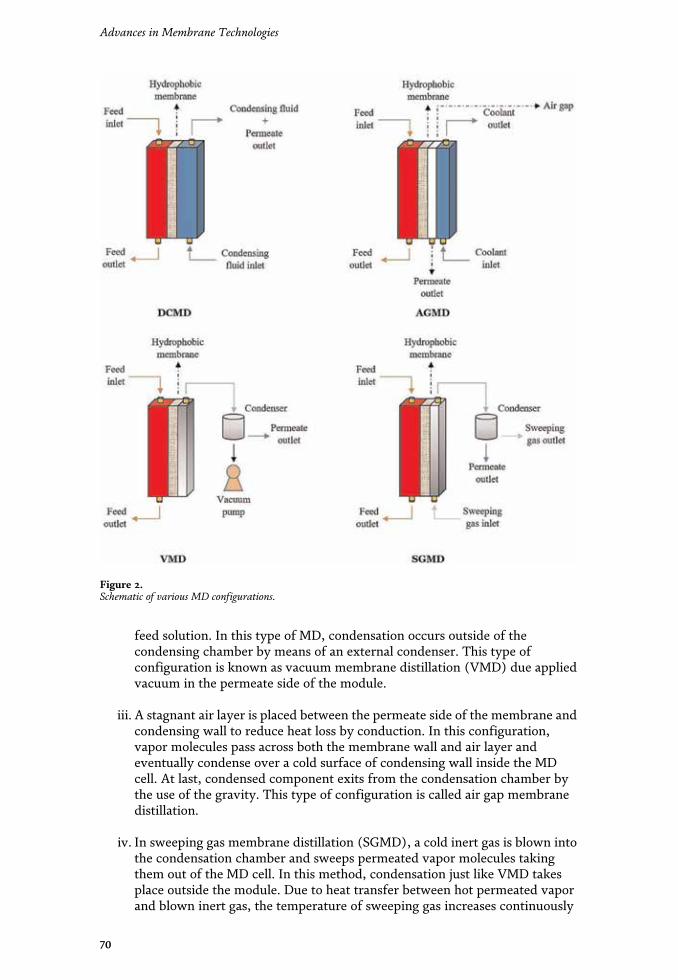
feed solution. In this type of MD, condensation occurs outside of thecondensing chamber by means of an external condenser. This type ofconfiguration is known as vacuum membrane distillation (VMD) due appliedvacuum in the permeate side of the module.
iii. A stagnant air layer is placed between the permeate side of the membrane andcondensing wall to reduce heat loss by conduction. In this configuration,vapor molecules pass across both the membrane wall and air layer andeventually condense over a cold surface of condensing wall inside the MDcell. At last, condensed component exits from the condensation chamber bythe use of the gravity. This type of configuration is called air gap membranedistillation.
iv. In sweeping gas membrane distillation (SGMD), a cold inert gas is blown intothe condensation chamber and sweeps permeated vapor molecules takingthem out of the MD cell. In this method, condensation just like VMD takesplace outside the module. Due to heat transfer between hot permeated vaporand blown inert gas, the temperature of sweeping gas increases continuously
Figure 2.Schematic of various MD configurations.
70
Advances in Membrane Technologies
along the condensing chamber length. To minimize the effect of heat transferbetween hot and cold stream, a cold wall is improvised in the permeate side ofthe module. This recently introduced method is called thermostatic sweepinggas membrane distillation (TSGMD). Table 1 presents details of various MDconfigurations.
2. MD membranes fabrication techniques and design
2.1 Membrane fabrication
As stated earlier, the main characteristics of MD membrane are porosity andhydrophobicity. MD membrane can be supported and unsupported and also might
MD configuration Application area Advantages Disadvantages
Direct contactmembranedistillation (DCMD)
• Seawaterdesalination
• Crystallization• Treatment of
dye effluents• Arsenic
removal fromaqueoussolution
• High permeate flux• Considered at commercial
scale
• Highconductiveheat loss
Vacuum membranedistillation (VMD) • Seawater
desalination• Treatment of
alcoholicsolution
• Recovery ofaromacompounds
• Treatment oftextilewastewaters
• High permeate flux• Considered at commercial
scale
• High risk ofmembranepore wetting
• Processcomplexity
Air gap membranedistillation (AGMD) • Seawater
desalination• Concentration
of fruit juices• Separation of
azeotropicmixtures
• VOC removal
• Low conductive heat loss• Process simplicity• Low risk of temperature
polarization (TP)
• Lower fluxthan DCMDand VMD
Sweeping gasmembranedistillation (SGMD)
• Brackish waterdesalination
• Separation ofazeotropicmixtures
• Wastewatertreatment
• VOC removal
• Reduction of the barrierto the mass transportthrough forced flow
• High risk oftemperaturepolarization(TP)
• Processcomplexity
Table 1.Properties of various MD configurations.
71
Membrane Distillation: Basics, Advances, and ApplicationsDOI: http://dx.doi.org/10.5772/intechopen.86952

be fabricated in the form of single-layer membrane, composite dual-layer mem-brane (hydrophobic/hydrophilic), and composite triple-layer membrane (hydro-phobic/hydrophilic/hydrophobic). The surface mean pore size of the membraneapplied in MD is between 100 Å and 1 μm.
Generally, MD membranes can be fabricated by track etching, sintering, phaseinversion, electrospinning, etc. Among these procedures, phase inversion is the mostapplied method. Also, several types of membranes are fabricated by combining theabovementioned methods. In 2013, Zhu et al. fabricated novel hollow fiber mem-brane by combining extrusion, sintering, and stretching [15]. Phase inversion methodis based on solidification of a homogenous polymeric solution by such several proce-dure such as non-solvent-induced phase separation (NIPS), evaporation-inducedphase separation (EIPS), thermally induced phase separation (TIPS), and vapor-induced phase separation (VIPS) in a controlled way [16]. NIPS and TIPS are themost commonly used techniques to fabricate MD membranes. In NIPS method, thepolymer is dissolved in appropriate solvent, and then the polymeric solution is castedon a glass plate or non-woven support. After casting, the polymeric film is immersedinto the non-solvent bath. After a while, two phases are formed: a polymer-rich phaseand a solvent-rich phase. Solvent/non-solvent exchange continues until the wholepolymer component becomes solid. To fabricate membranes by TIPS technique, asolution containing polymer/diluent must be prepared and then is casted via favor-able procedure. After precipitation of polymer component by cooling method, dilu-ent extraction causes pore formation [17–20]. In recent years, electrospinningtechnique has been suggested by many researchers to prepare well-suited MD mem-branes [21–23]. To prepare electrospun nanofibrous membranes (ENMs), a poly-meric solution must be poured into a needle-equipped syringe. Electrospinningapparatus consists of a high-voltage electric source, needle-equipped syringe, syringepump, and a collector. After overcoming the surface tension, polymeric jet is directedtoward a collector (often rotating drum) in the shape of cylindrical nanofibers. Toobtain uniform membrane structure, syringe pump has axial movement [13]. Theschematic of electrospinning process is shown in Figure 3. The properties of com-mercial membranes used in MD are presented in Table 2.
2.2 MD module design
Membrane modules are one of the most important parts of MD process whichcontrol the operation parameters. Different types of MD module are manufacturedso far especially for each kind of MD configurations. MD module must possess
Figure 3.Schematic of electrospinning process. Source: Reprinted from [24].
72
Advances in Membrane Technologies
Membranecommercialcode
Membranetype
Producer Material Porosity(%)
Membranethickness (μm)
Reference
TF200 Flat sheet Gelman PTFE/PP 80 178 [25]
GVHP Flat sheet Millipore PVDF 70–75 110 [26]
MD020TP2N Tubular Enka Microdyn PP 75 1550 [27]
Celgard X-20 Tubular HoechstCelanese Co.
PP 35 25 [28]
G-4.0-6-7 Flat sheet Gore-Tex SepGmbH
PTFE 80 100 [29]
PP 50/200 Hollowfiber
AccurelMembrana
PP 0.5 200 [30]
3 MA Flat sheet 3 M Corporation PP 60 91 [31]
Table 2.Commercial membranes recently used in MD.
Figure 4.Different MDmodules: (a) plate and frame, (b) capillary, and (c) spiral wound. Source: Reprinted from [32].
73
Membrane Distillation: Basics, Advances, and ApplicationsDOI: http://dx.doi.org/10.5772/intechopen.86952

required characteristics such as high packing density; high mechanical strength andchemical and thermal stability; low pressure drop; low heat loss; and user-friendly(for cleaning or membrane replacement). As presented in Figure 4, MD modulesare divided into three major groups including plate and frame, spiral wound, andcapillary (Figure 4).
i. Plate and frame module is the simplest one among all MD modules. It consistsof a series of flat sheet membranes, spacers, and supports which areconnected in axial direction. This type of MD module has shown goodpotential for commercialization due to its tangential flow in which the liquidstream is in direct contact with the membrane surface.
ii. In spiral wound module, supported or unsupported flat sheet membranes arewrapped around a central tube in a spiral formation. Spiral wound modulecan provide tangential flow and represent high surface to volume ratio whichmakes it the desirable choice for applying in MD process.
iii. Capillary modules are divided into three main categories: (1) capillarymodules, (2) tubular modules, and (3) hollow fiber modules. Capillary,tubular, and hollow fiber membranes are distinguished by their inner andouter diameter which effects on their packing density. The membranes withdiameter ranging from 5 to 25 mm are classified as tubular membranes(packing density 300 m2/m3). Capillary membranes often have pores withdiameter between 1 and 3 mm (packing density 1200 m2/m3). The diametersof hollow fiber membranes are usually below 1 mm (packing density 500–9000 m2/m3) [33]. These types of membranes are typically assembled andbundled in shell and tube modules. Table 3 summarizes some MD modulesused in desalination process.
3. MD membrane characteristics
MDmembranes should have such characteristics to show their best performancein MD process. Before conducting MD tests, the applied membranes must be
Moduleproducer
Effectivemembranearea (m2)
Membranematerial
Permeateflux (kg/m2h)
MDconfiguration
Type ofmodule
Reference
SEP GmbH 4 PTFE 2.5–12.5 DCMD Spiral [34]
GE OsmonicsSEPA CF
0.014 PTFE 22.3 DCMD Plateand frame
[35]
Microdyn 0.1 PP 3.6 VMD Capillary [36]
Enka-Microdyn
0.036 PP 4 DCMD Tubular [37]
ScarabdevelopmentAB
2.8 PTFE 6.5 AGMD Plate andframe
[38]
Microdyn 0.1 PP 13 DCMD Hollowfiber
[37]
Table 3.Commercial MD modules with different configurations.
74
Advances in Membrane Technologies
characterized by different methods to abstain from wetting during experiments.MD membrane characterization techniques are as follows: liquid entrypressure (LEP), porosity, thermal conductivity, water contact angle, andmembrane thickness.
3.1 Liquid entry pressure (LEP)
To abstain from membrane wetting, the MDmembrane should have three majorproperties, simultaneously: high water contact angle, high hydrophobicity, andnarrow pore size distribution. However, membrane wetting may take place andeffect on membrane performance when the feed solution is in direct contact withmembrane surface. When the hydraulic transmembrane pressure overstepsLEP, aqueous solution components will prevail over the surface tension and wetmembrane pores. Generally, LEP is the maximum pressure value applied onto thefeed solution to be treated before the membrane pore wetting happens. Based onCantor-Laplace equation, the LEP value depends on surface contact angle (θ),surface tension (γL), geometric coefficient (β), and maximum poreradius (rmax) [39]:
LEP ¼ �2βγLcosθrmax
(1)
As can be comprehended from Cantor-Laplace equation, increasing in surfacecontact angle or decreasing of maximum pore size will enhance LEP value.
3.2 Porosity
Porosity of MD membranes must be as high as possible until the wetting phe-nomenon does not occur. Porous surface can lead to higher permeate flux. Gener-ally, the ratio of free volume to total volume of the membrane is called porosity. InMD, the ratio between the macrovoid volume and total volume of the membrane iscalculated by gravimetric procedure [40]. This technique is based on measuringmembrane weights applying a wetting liquid such as 2-propanol, which goes insidethe pores, and weighing the membrane before and after wetting:
ε ¼ WW �WDð Þ=ρwlWW �WDð Þ=ρAl½ � þWD=ρP
(2)
where WW , WD, ρwl, and ρP are the weights of wet and dry membrane and thedensity of wetting liquid and hydrophobic polymer.
3.3 Water contact angle
Tendency of membrane surface to be wetted by liquids is often measured byliquid contact angle analysis. In MD, because water is the major component of thefeed solution, water contact angle is calculated for determining surface tendency towater droplets. In this technique, the angle between water droplet and membranesurface is calculated. To minimize the errors of calculation, various locations ofmembrane surface are selected randomly, and the average contact angle isreported as water contact angle. It should be noted that the effect of mean poresize and surface roughness should be considered to specify the exact watercontact angle.
75
Membrane Distillation: Basics, Advances, and ApplicationsDOI: http://dx.doi.org/10.5772/intechopen.86952

3.4 Thermal conductivity
Thermal conductivity of MD membranes must be as low as possible. Heat loss invarious MD configurations is attributed to the membrane material and existed gasesin the membrane pores. Increasing in thermal conductivity could reduce mass fluxwhich is undesirable for MD process. Since the water vapor thermal conductivity isone order of magnitude lower than polymeric materials to be used in MD, increas-ing membrane surface porosity could lead to heat loss reduction. So, the presence ofmacrovoids in the membrane surface will result in reducing thermal conductivity.As stated above, the thermal conductivity of MD membranes is related to boththermal conductivity of polymer (kp) and gases (kg):
k ¼ εkg þ 1� εð Þkp (3)
It is worth mentioning that most of the polymers used in MD membranespossess similar conductivity value. For example, thermal conductivity of PP, PTFE,and PVDF is about 0.11–0.16 (W/m2 K), 0.25–0.27 (W/m2 K), and 0.17–0.19(W/m2 K), respectively [41].
3.5 Membrane thickness
The membrane thickness is one of the most effective characteristics on MDmembrane performance. The membrane thickness and membrane permeate fluxare inversely related to each other. As the membrane becomes thinner, the perme-ate flux enhances due to the reduction of mass transfer resistance. On the otherhand, when the membrane thickness increases, the heat loss decreases. So, there is atrade-off between advantage (lower heat loss) and disadvantage (lower permeateflux) of thicker membrane. It should be noted that the effect of membrane thick-ness in AGMD on mass transfer can be passed up, because the stagnant air layercontrols mass transfer rate.
4. MD process conditions
The effects of various operational parameters on MD performance must becontrolled to achieve the best results. Some of these parameters are as follows: (i)feed temperature, (ii) feed concentration, (iii) membrane type, (iv) feed flow rate,and (v) long operation.
4.1 Feed temperature
The feed temperature has a powerful effect on the permeate flux. Based on theAntoine equation, by increasing the temperature, the vapor pressure increasesexponentially. So, the permeate flux will increase exponentially by increasing of thetemperature [42]. When the temperature difference between the feed and permeateside of the membrane is kept constant, the distillate flux will enhance when thetemperature of the feed side increases, which means the vapor pressure is moredependent to the higher temperature. In other words, the increase in vapor pressuregradient when the hot fluid temperature increases is more than the time which thecold fluid temperature decreases. Also, some researchers found out that increasingthe temperature difference between the feed and permeate side of the membranewill increase diffusion factor positively [43–45].
76
Advances in Membrane Technologies
4.2 Feed concentration
When the feed concentration increases, the permeate flux will decrease consid-erably due to the reduction of vapor pressure and increment of temperature polar-ization. Generally, when NaCl solution concentration was increased from 0 to2 mol, about 12% decline was observed in permeate flux [45]. In fact, reduction ofvapor pressure induced by concentration increment caused distillate flux reduction.Also, researchers demonstrated that there are three reasons for flux decline as aresult of increasing feed concentration, reduction of water activity, reduction ofmass transfer coefficient caused by concentration polarization, and reduction ofheat transfer coefficient caused by decline in membrane surface temperature [46].
4.3 Membrane type
As discussed earlier, MD membranes should have porous surface with highmean pore size. The distillate flux is proportional to the surface pore size andporosity and inversely proportional to the thickness of the membrane and poretortuosity. Also, membranes must present high LEP value to prevent membranewetting. Furthermore, unsupported membranes with a certain pore size showedhigher flux than supported membranes with the same pore size [47].
4.4 Feed flow rate
The effects of feed flow rate on SGMD are negligible, while it is considerable inDCMD and VMD. In general, increasing of feed flow rate leads to permeate fluxincrement. This is due to the improved mixing and the reduction of temperatureboundary layer thickness on the feed side of the membrane. By increasing feed flowrate, the laminar flow regime turns into a turbulent regime, and the distillate fluxreaches asymptotic values [48]. In fact, by increasing of feed flow rate, Reynoldsnumber and heat transfer coefficient increase which lead to the reduction of tem-perature polarization.
4.5 Longtime operation
MDmembranes must show stable performance during experiments for days andmonths. Actually, membrane stability is the most important challenge in MD com-mercialization. Several experiments showed after membrane compaction, the per-meate flux increased at initial hours of the tests [49–51]. Then, the flux was reduceduntil reaching a steady state. Partial pore wetting and fouling were conveyed asreasons for the flux reduction during longtime MD experiments [46].
5. Transport mechanisms
5.1 Heat transfer
Measurement of heat transfer in MD is extremely complicated because ofsimultaneous heat and mass transfer. Based on the principal theory of heat transfer,a thermal boundary layer is formed at a fluid/solid interface with different temper-atures. In MD module, a hot fluid is in direct contact with solid surface (membrane,with a thickness of δ) in which the thermal boundary layer will be formed adjacentto the membrane surface. Due to the existence of temperature gradient in MDmodule, two boundary layers will be formed on the feed side (with a thickness of δF)
77
Membrane Distillation: Basics, Advances, and ApplicationsDOI: http://dx.doi.org/10.5772/intechopen.86952

and the permeate side (with a thickness of δP) of the hydrophobic membrane. Insidethe thermal boundary layer, the feed temperature reduces from TbF (feed bulk) toTmF (membrane surface). Also, the permeate temperature increases from TbP (per-meate bulk) to TmP (membrane surface). Since MD process depends on vaporizationof a component, the latent heat should be transitioned from feed bulk to the mem-brane surface through the thermal boundary layer. Heat transfer coefficient(hFÞ plays a key role in heat transfer across the boundary layer. So, the heat fluxbetween the feed bulk and membrane surface is defined as
qF ¼ hF TbF � TmFð Þ (4)
When vaporization takes place at the membrane surface, the latent heat istransferred to the permeate side of the membrane with vapor stream:
qL ¼ N � ΔHvap (5)
where N (mol/m2 K) is the vapor flux through the membrane pores, ΔHvap
(J/mol) is the latent heat of vaporization, and qL (W/m2) is the heat transferredbecause of volatile component evaporation. There are some other types of heattransfer in MD process including heat transfer via gas-filled pores (qmÞ and heattransfer across the permeate side of the membrane qP
� �:
qm ¼ hm TmF � TmPð Þ (6)
where hm is the heat transfer coefficient of the membrane which depends onboth the heat transfer coefficient of membrane material and the gas which fills themembrane pores. So, the heat transfer mechanism in MD process consists of threedifferent steps: (i) heat transfer through the thermal boundary layer at the feedside, (ii) heat transfer through the membrane, and (iii) heat transfer through thethermal boundary layer at the permeate side.
5.2 Mass transfer
In general, mass transfer mechanism in MD consists of three major categoriesincluding Knudsen flow theory, viscous flow theory, and molecular diffusion the-ory. In MD, surface penetration is ignored because the penetration area of mem-brane matrix is much lower than the volume of the pores [46]. Moreover, as isstated earlier, MD membrane material has low affinity to water molecules. So, thecontribution of transport through the membrane matrix can be ignored. The keyparameter to recognize the governing mass transfer mechanism in MD module isKnudsen number (Kn) which is determined as
Kn ¼ λidp
(7)
where λi is the mean free path of the transferred vapor molecules through thepores with a size of dp. When the Knudsen number is greater than one, the possi-bility of collisions between vapor molecule and pore wall is more than the collisionsbetween vapor molecule and another one. In this case, the permeability through themembrane pores when a uniform pore size dp,m is assumed can be calculated fromthe following Equation [29]:
78
Advances in Membrane Technologies
βk,m ¼ 23εdp,mτδ
2πMRT
� �0:5
(8)
where ε, τ, and δ are membrane porosity, membrane tortuosity, and membranethickness, respectively. When the Knudsen number is lower than 0.01, moleculardiffusion is the governing mass transfer mechanism, and the membrane permeabil-ity is defined as [26]
βM,m ¼ π
4RTPDPair
dp,m2
τδ
!(9)
where P, D, and Pair represent the total pressure within a pore, the diffusioncoefficient, and air pressure within a pore, respectively. When hydrostatic pressureis used over a membrane owning pores with greater size than mean free path,viscous flow will be the governing mass transfer mechanism. In this situation, thepossibility of collisions among vapor molecules is more than the collisions betweenvapor molecule and pore wall. When a uniform pore size dp,m is assumed for themembrane pores, the permeability can be measured with the followingequation [44]:
βV,m ¼ ε
32RTPm
μ
dp,m2
τδ
!(10)
where μ and Pm are the viscosity of transferred vapor molecules and averagepressure of the pores.
6. MD applications
MD is going to be an attractive technology for separation processes due to itsunique properties. Dealing with water as a key component of chemical and physicalprocesses and high separation factor are the most attractive characteristics of MDtechnology. Nowadays, MD is used in environmental, food, pharmaceutical, andnanotechnology industries. Also, MD can be used as a single-step process or can becombined with other separation techniques as a last stage [52]. Some applications ofMD are the following:
1. Desalination of seawater, brackish water, groundwater, and brines broughtfrom other units.
2. Industrial wastewater treatment including radioactive waste treatment,concentration of nonvolatile acids, volatile acid recovery from industrialeffluents, salt recovery by membrane distillation crystallization (MDC), andtextile industry effluents.
3. Preparation of distilled water, pure water, and ultrapure water for medical andpharmaceutical purposes.
4.Production of liquid food concentrates such as mandarin juice, sucrosesolution, whey, and apple juice.
79
Membrane Distillation: Basics, Advances, and ApplicationsDOI: http://dx.doi.org/10.5772/intechopen.86952

5. Volatiles removal from fruit juice, alcohols, halogenated VOCs, and benzeneby VMD and SGMD.
6.Dealcoholization of fermented beverages and enhanced ethanol productionusing DCMD.
The most important MD application is desalination of wastewaters includinghigh percentage of salt molecules in order for safe discharge into the environmentor to produce drinkable, pure, and ultrapure water. The theoretical 100% rejectionof nonvolatile solutes, colloids, and biological matters by MD guarantees the elimi-nation of all unwanted solutes that are often existing in water sources. The treatedwater by MD shows an electrical conductivity as low as 800 μS/cm with totaldissolved solids (TDS) of 0.6 ppm [53].
7. Process challenges
The principal challenges of MD process are temperature polarization,concentration polarization (CP), and fouling of contaminants on the membranesurface. These challenges must be controlled to avoid underperformance in MDprocess. One of the most undesirable problems in MD is temperaturepolarization in which the temperature gradient is created between bulk feed andmembrane surface at liquid/vapor interface. In fact, by vaporization of a compo-nent, liquid bulk temperature decreases, while vapor temperature increasesinstead. This phenomenon causes a reduction of temperature difference leading topermeate flux decline. Temperature polarization coefficient (TPC) is oftendefined as the ratio of boundary layer resistance to the total heat transferresistance:
TPC ¼ TmF � TmP
TbF � TbP(11)
where superscripts m and b specify the temperature near the membrane surfaceand bulk. Based on scientific reports, a reasonable value for TPC to design MDsystems lies between 0.4 and 0.7 [54]. Concentration polarization is another prob-lem in MD process. When evaporation occurs, the solute concentration near themembrane surface becomes greater than that of the bulk feed. Similar to the tem-perature polarization effect, the concentration cannot be measured due to thesimultaneous heat and mass transfer. Concentration polarization coefficient (CPC)is often defined as the ratio of the solute concentration near the membrane to thesolute concentration in the bulk feed:
CPC ¼ CmF
CbF(12)
Fouling of contaminants on the membrane surface is also a problem in MDprocess. Although fouling has lower effect on MD than other pressure-drivenmembrane processes, it often causes underperformance in membrane process.Fouling and contaminant deposition on membrane surface cause the reduction ofeffective membrane area and membrane wetting resulting in distillate flux declineand low rejection. So, to reach maximum efficiency in MD process, the effects ofthese problems should be reduced as much as possible.
80
Advances in Membrane Technologies
8. Recent developments and innovations in hybrid MD systems
MD can be combined with other membrane technologies such as RO,microfiltration (MF), and nanofiltration (NF) as well as common distillation sys-tems (i.e., multistage flash (MSF)) and low-cost energy sources [55]. These hybridsystems will offer high-quality products and lower energy consumption bothin the system installation and the discharging concentrated brine. In fact, MDhybrid systems are beneficial if they can rectify other system disadvantages.
Generally, MD hybrid systems can be divided into two major groups: (i) inte-grated MD systems with membrane processes and (ii) integrated MD systems withother processes. The combination of MD with ultrafiltration (UF) for treatment ofoily wastewater was investigated by Gryta et al. [56]. DCMD was applied as finalpurification technique after UF. The hot UF permeate entered into the DCMD celllinked in parallel form. The MD permeate is collected outside the chamber, and theoil concentrate is returned to the UF modules as feed. The product collected fromthe UF module commonly contains less than 5 ppm of oil. An additional distillationprocess over the UF permeate leads to a complete elimination of oil from wastewa-ter with a high removal percentage of 99.9% for total dissolved solids. As an anotherhybrid system, MD was integrated with RO for desalination by Drioli et al. [57]. MDwas suggested to desalinate RO brine (75 g/l) at a temperature of 35°C to improveboth efficiency and water recovery. Since MD is less sensitive to brine concentrationthan RO, more potable water can be obtained by RO/MD hybrid system. The resultsshowed that the recovery factor of hybrid system was about 87% which was higherthan that of MD (77%) and RO (40%). There are also some reports about using NF/MD and PV/MF/MD hybrid systems to produce high-quality products [53, 58].
As stated earlier, MD can be integrated with other chemical and physical sepa-ration processes. Gryta et al. studied the performance of hybrid bioreactor/MDsystem to produce ethanol [59]. The fermentation of sugar with Saccharomycescerevisiae (commonly known as baker’s yeast) results in the formation of by-products, which can be eliminated by MD. This integration leads to improve theefficiency of sugar conversion to ethanol. The results of the fermentation tests withand without integration with MD process corroborated the advantages of the fer-mentation carried out with continuous elimination of fermented products by theMD module. One of the interesting characteristics of MD process is its flexibility touse renewable energy source such as nuclear power and solar energy for heating thefeed solution [60, 61]. Khayet et al. investigated the possibility of nuclear desalina-tion by DCMD coupled with a nuclear reactor [62]. The results of experimentsconfirmed the feasibility of water desalination by consuming the heat and electric-ity generated in nuclear power plant. From the stated examples of MD hybridsystems, it is clear that all of the investigation was in laboratory or pilot scale. So,more investigation must be performed in order to remove the obstacles from com-mercialization of MD hybrid systems.
9. Economics and energy consumption in MD
As it was stated throughout this chapter, MD process requires an energy sourcefor heating the feed to a specific temperature. The ability of coupling with renew-able energy sources such as solar and geothermal energy or industrial waste heatconverts MD from expensive laboratory scale process to beneficial industrial one.So, especially in desalination, the water production cost (WPC) will decrease byapplying a low-cost energy source. It is worth mentioning that current seawater
81
Membrane Distillation: Basics, Advances, and ApplicationsDOI: http://dx.doi.org/10.5772/intechopen.86952

desalination capacity is about 27 million m3/day which only meets 3% of freshwaterdemand. In fact, WPCs for industrial units are less than $1/m3, whereas it may varybetween $1/m3 and 3/m3 small-scale units. While solar energy-based processes aretypically expensive due to the high capital cost, they could slowly become compet-itive with conventional energy sources in the future. It must be noted that eventhough the WPCs of solar-powered MD (SPMD) are considerably high, it could bean interesting alternative for water production in remote areas. Generally, lowerenergy consumption or using low-cost energy sources would reduce the WPC.Table 4 summarizes energy consumption of different separation processes.
10. Conclusion and future prospects in MD
After several decades of persistent investigation for understanding the conceptof MD and its difficulties, there are still many obstacles that must be eliminatedfor industrialization. Based on recent development, MD process is able to be used ina vast variety of applications such as desalination and wastewater treatment.Although MD process still suffers from some problems which limited its perfor-mance such as high-energy consumption, longtime operation, wetting and fouling,and lack of appropriate module, different reports have been presented to enhancepermeate flux and solute retention and decrease energy consumption in MD pro-cess, including developed membrane modules and hybrid MD systems. So far, theeffects of MD operational parameters have been studied over and over, but someareas related to commercialization field are still overlooked or investigatedscarcely. Therefore, a vigorous motivation is required for research on the neglectedareas such as membrane module design or scale-up variables both in experimentaland modeling fields in which the obtained experimental data will be extremelybeneficial.
Nomenclature
MD membrane distillationVLE vapor-liquid equilibriumPV pervaporationPTFE polytetrafluoroethylenePE polyethylene
Separation process Productionrate
Energy consumption(kWh/m3)
Reference
RO standard 105,000 m3/day 4.5 [63]
SPMD 5–27 l/m2 h 200–300 [64]
AGMD 5.2 l/m2 h 1 [65]
VMD 0.71 l/m2 h 3.2 [66]
Brackish water RO (BWRO) withphotovoltaic (PV) panels
0.2 m3/day 1.3 [67]
Solar still 2–6 l/m2 day 640 [68]
Table 4.Estimated energy consumption of different separation processes used in desalination.
82
Advances in Membrane Technologies
PVC polyvinyl chlorideRO reverse osmosisAGMD air gap membrane distillationDCMD direct contact membrane distillationPP polypropyleneVOCs volatile organic compoundsVMD vacuum membrane distillationSGMD sweeping gas membrane distillationTSGMD thermostatic sweeping gas membrane distillationNIPS non-solvent induced phase separationEIPS evaporation induced phase separationTIPS thermally induced phase separationVIPS vapor induced phase separationENMs electrospun nanofibrous membranesLEP liquid entry pressureKn Knudsen numberMDC membrane distillation crystallizationTDSs total dissolved solidsTP temperature polarizationCP concentration polarizationTPC temperature polarization coefficientCPC concentration polarization coefficientMF microfiltrationNF nanofiltrationMSF multistage flashUF ultrafiltrationWPC water production costSPMD solar-powered membrane distillationBWRO brackish water reverse osmosisPV photovoltaic
Author details
Mohammad Reza Shirzad Kebria and Ahmad Rahimpour*Department of Chemical Engineering, Babol Noshirvani University of Technology,Babol, Iran
*Address all correspondence to: [email protected]
© 2020TheAuthor(s). Licensee IntechOpen.Distributed under the terms of theCreativeCommonsAttribution -NonCommercial 4.0 License (https://creativecommons.org/licenses/by-nc/4.0/),which permits use, distribution and reproduction fornon-commercial purposes, provided the original is properly cited. –NC
83
Membrane Distillation: Basics, Advances, and ApplicationsDOI: http://dx.doi.org/10.5772/intechopen.86952

References
[1] Smolders K, Franken A. Terminologyfor membrane distillation. Desalination.1989;72:249-262
[2] Bodell BR. Silicone rubber vapordiffusion in saline water distillation,United States Patent Serial No. 285,032;1963
[3] Weyl PK. Recovery of demineralizedwater from saline waters, United StatesPatent 3,340,186; 1967
[4] Findley M. Vaporization throughporous membranes. Industrial andEngineering Chemistry Process Designand Development. 1967;6:226-230
[5] Gore D. Gore-Tex membranedistillation. In: Proc. of the 10th Ann.Convention of the Water SupplyImprovement Assoc.; Honolulu, HI,USA. 1982. pp. 25-29
[6] Andersson S-I, Kjellander N, RodesjöB. Design and field tests of a newmembrane distillation desalinationprocess. Desalination. 1985;56:345-354
[7] Carlsson L. The new generation insea water desalination SU membranedistillation system. Desalination. 1983;45:221-222
[8] Schneider K, Hölz W, Wollbeck R,Ripperger S. Membranes and modulesfor transmembrane distillation. Journalof Membrane Science. 1988;39:25-42
[9] Schneider K, van Gassel TJ.Membrane distillation. ChemieIngenieur Technik. 1984;56:514-521
[10] Van Gassel T, Schneider K. Anenergy-efficient membrane distillationprocess. In: Membranes and MembraneProcesses. Boston: Springer; 1986.pp. 343-348
[11] Esato K, Eiseman B. Experimentalevaluation of Gore-Tex membrane
oxygenator. The Journal of Thoracic andCardiovascular Surgery. 1975;69:690-697
[12] Enka AG. Catalogue Presented atEurope-Japan Joint Congress onMembranes and Membrane Processes;Stresa, Italy; 1984
[13] Jafari A, Kebria MRS, Rahimpour A,Bakeri G. Graphene quantum dotsmodified polyvinylidenefluride (PVDF)nanofibrous membranes with enhancedperformance for air gap membranedistillation. Chemical Engineering andProcessing Process Intensification. 2018;126:222-231
[14] Lawson KW, Lloyd DR. Membranedistillation. II. Direct contact MD.Journal of Membrane Science. 1996;120:123-133
[15] Zhu H, Wang H, Wang F, Guo Y,Zhang H, Chen J. Preparation andproperties of PTFE hollow fibermembranes for desalination throughvacuum membrane distillation. Journalof Membrane Science. 2013;446:145-153
[16] Lu W, Yuan Z, Zhao Y, Zhang H,Zhang H, Li X. Porous membranes insecondary battery technologies.Chemical Society Reviews. 2017;46:2199-2236
[17] Gu M, Zhang J, Wang X, Tao H, GeL. Formation of poly (vinylidenefluoride) (PVDF) membranes viathermally induced phase separation.Desalination. 2006;192:160-167
[18] Karimi H, Rahimpour A, KebriaMRS. Pesticides removal from waterusing modified piperazine-basednanofiltration (NF) membranes.Desalination and Water Treatment.2016;57:24844-24854
[19] Kebria MRS, Jahanshahi M.Nanofiltration membrane synthesized
84
Advances in Membrane Technologies
from polyethyleneimine for removal ofMgSO4 from aqueous solution.International Journal of Engineering.2014;27:1173-1178
[20] Rajabzadeh S, Maruyama T, SotaniT, Matsuyama H. Preparation of PVDFhollow fiber membrane from a ternarypolymer/solvent/nonsolvent system viathermally induced phase separation(TIPS) method. Separation andPurification Technology. 2008;63:415-423
[21] Kebria MRS, Rahimpour A, BakeriG, Abedini R. Experimental andtheoretical investigation of thin ZIF-8/chitosan coated layer on air gapmembrane distillation performance ofPVDF membrane. Desalination. 2019;450:21-32
[22] Kebria MS, Rahimpour A, AbediniR. Preparation and characterisation ofnew microporous Elvaloy4170 coatedPVDF membrane for desalination by airgap membrane distillation. Micro &Nano Letters. 2019;14:551-555
[23] Lalia BS, Guillen-Burrieza E,Arafat HA, Hashaikeh R.Fabrication and characterizationof polyvinylidenefluoride-co-hexafluoropropylene (PVDF-HFP)electrospun membranes for directcontact membrane distillation. Journalof Membrane Science. 2013;428:104-115
[24] Esfahani MR, Aktij SA, DabaghianZ, Firouzjaei MD, Rahimpour A, Eke J,et al. Nanocomposite membranes forwater separation and purification:Fabrication, modification, andapplications. Separation andPurification Technology. 2019;213:465-499
[25] Kiai H, García-Payo M, Hafidi A,Khayet M. Application of membranedistillation technology in the treatmentof table olive wastewaters for phenoliccompounds concentration and highquality water production. Chemical
Engineering and Processing ProcessIntensification. 2014;86:153-161
[26] Martinez L, Rodriguez-Maroto JM.Membrane thickness reduction effectson direct contact membrane distillationperformance. Journal of MembraneScience. 2008;312:143-156
[27] Khayet M. Membranes andtheoretical modeling of membranedistillation: A review. Advances inColloid and Interface Science. 2011;164:56-88
[28] Drioli E, Ali A, Macedonio F.Membrane distillation: Recentdevelopments and perspectives.Desalination. 2015;356:56-84
[29] Khayet M, Velázquez A, Mengual JI.Modelling mass transport through aporous partition: Effect of pore sizedistribution. Journal of Non-Equilibrium Thermodynamics. 2004;29:279-299
[30] Li B, Sirkar KK. Novel membraneand device for direct contact membranedistillation-based desalination process.Industrial and Engineering ChemistryResearch. 2004;43:5300-5309
[31] Moghaddam Kamrani P, BakhtiariO, Kazemi P, Mohammadi T.Theoretical modeling of direct contactmembrane distillation (DCMD): Effectsof operation parameters on flux.Desalination and Water Treatment.2015;56:2013-2022
[32] Tarleton ES. Chapter 3. In: Progressin Filtration and Separation. London:Academic Press; 2014. pp. 61-99
[33] Chiam C-K, Sarbatly R. Vacuummembrane distillation processes foraqueous solution treatment—A review.Chemical Engineering and ProcessingProcess Intensification. 2013;74:27-54
[34] Zakrzewska-Trznadel G,Harasimowicz M, Chmielewski AG.
85
Membrane Distillation: Basics, Advances, and ApplicationsDOI: http://dx.doi.org/10.5772/intechopen.86952

Concentration of radioactivecomponents in liquid low-levelradioactive waste by membranedistillation. Journal of MembraneScience. 1999;163:257-264
[35] Dow N, Zhang J, Duke M, Li JD,Gray SR, Ostarcevic E. MembraneDistillation of Brine Wastes; 2008
[36] Criscuoli A, Carnevale M, Drioli E.Modeling the performance of flat andcapillary membrane modules in vacuummembrane distillation. Journal ofMembrane Science. 2013;447:369-375
[37] Al-Obaidani S, Curcio E, MacedonioF, Di Profio G, Al-Hinai H, Drioli E.Potential of membrane distillation inseawater desalination: Thermalefficiency, sensitivity study and costestimation. Journal of MembraneScience. 2008;323:85-98
[38] Guillén-Burrieza E, Blanco J,Zaragoza G, Alarcón D-C, Palenzuela P,Ibarra M, et al. Experimental analysis ofan air gap membrane distillation solardesalination pilot system. Journal ofMembrane Science. 2011;379:386-396
[39] Franken A, Nolten J, Mulder M,Bargeman D, Smolders C. Wettingcriteria for the applicability ofmembrane distillation. Journal ofMembrane Science. 1987;33:315-328
[40] Liao Y, Wang R, Tian M, Qiu C,Fane AG. Fabrication of polyvinylidenefluoride (PVDF) nanofiber membranesby electro-spinning for direct contactmembrane distillation. Journal ofMembrane Science. 2013;425:30-39
[41] Phattaranawik J, Jiraratananon R,Fane AG. Heat transport and membranedistillation coefficients in direct contactmembrane distillation. Journal ofMembrane Science. 2003;212:177-193
[42] Alklaibi AM, Lior N. Membrane-distillation desalination: Status andpotential. Desalination. 2005;171:111-131
[43] Larimi YN, Mollahosseini A,Mohammadi P, Tabatabaei M. Wastepolymers recycling in biodiesel as astrategy to simultaneously enhance fuelproperties and recycle the waste:Realistic simulation and economicalassessment approach. Biofuels. 2016;7:559-570
[44] Mollahosseini A, Abdelrasoul A.Recent advances in thin film compositesmembranes for brackish groundwatertreatment with critical focus onSaskatchewan water sources. Journal ofEnvironmental Sciences. 2019;81:181-194
[45] Qtaishat M, Matsuura T, Kruczek B,Khayet M. Heat and mass transferanalysis in direct contact membranedistillation. Desalination. 2008;219:272-292
[46] Lawson KW, Lloyd DR. Membranedistillation. Journal of MembraneScience. 1997;124:1-25
[47] Izquierdo-Gil M, Garcıa-Payo M,Fernández-Pineda C. Air gap membranedistillation of sucrose aqueous solutions.Journal of Membrane Science. 1999;155:291-307
[48] Khayet M, Godino M, Mengual J.Possibility of nuclear desalinationthrough various membrane distillationconfigurations: A comparative study.International Journal of NuclearDesalination. 2003;1:30-46
[49] Banat FA, Simandl J. Theoreticaland experimental study in membranedistillation. Desalination. 1994;95:39-52
[50] Banat FA, Simandl J. Desalinationby Membrane Distillation: A ParametricStudy; 1998
[51] Drioli E, Wu Y. Membranedistillation: An experimental study.Desalination. 1985;53:339-346
[52] Van der Bruggen B. Integratedmembrane separation processes for
86
Advances in Membrane Technologies
recycling of valuable wastewaterstreams: Nanofiltration, membranedistillation, and membrane crystallizersrevisited. Industrial and EngineeringChemistry Research. 2013;52:10335-10341
[53] Karakulski K, Gryta M, Morawski A.Membrane processes used for potablewater quality improvement.Desalination. 2002;145:315-319
[54] Schofield R, Fane A, Fell C. Heatand mass transfer in membranedistillation. Journal of MembraneScience. 1987;33:299-313
[55] Koschikowski J, Wieghaus M,Rommel M. Solar thermal-drivendesalination plants based on membranedistillation. Desalination. 2003;156:295-304
[56] Gryta M, Karakulski K, Morawski A.Purification of oily wastewater byhybrid UF/MD. Water Research. 2001;35:3665-3669
[57] Drioli E, Lagana F, Criscuoli A,Barbieri G. Integrated membraneoperations in desalination processes.Desalination. 1999;122:141-145
[58] Johnson R, Sun J, Sun J. Apervaporation-microfiltration-osmoticdistillation hybrid process for theconcentration of ethanol-water extractsof the Echinacea plant. Journal ofMembrane Science. 2002;209:221-232
[59] Gryta M. The fermentation processintegrated with membrane distillation.Separation and Purification Technology.2001;24:283-296
[60] Mollahosseini A, Abdelrasoul A,Sheibany S, Amini M, Salestan SK.Renewable energy-driven desalinationopportunities—A case study. Journal ofEnvironmental Management. 2019;239:187-197
[61] Mollahosseini A, Hosseini SA,Jabbari M, Figoli A, Rahimpour A.
Renewable energy management andmarket in Iran: A holistic review oncurrent state and future demands.Renewable and Sustainable EnergyReviews. 2017;80:774-788
[62] Khayet M, Mengual J, Zakrzewska-Trznadel G. Direct contact membranedistillation for nuclear desalination, partII: Experiments with radioactivesolutions. International Journal ofNuclear Desalination. 2006;2:56-73
[63] Meindersma G, Guijt C, De Haan A.Desalination and water recycling by airgap membrane distillation. Desalination.2006;187:291-301
[64] Banat F, Jwaied N, Rommel M,Koschikowski J, Wieghaus M.Performance evaluation of the “largeSMADES” autonomous desalinationsolar-driven membrane distillation plantin Aqaba, Jordan. Desalination. 2007;217:17-28
[65] Gazagnes L, Cerneaux S, Persin M,Prouzet E, Larbot A. Desalination ofsodium chloride solutions and seawaterwith hydrophobic ceramic membranes.Desalination. 2007;217:260-266
[66] Cabassud C, Wirth D. Membranedistillation for water desalination: Howto chose an appropriate membrane?Desalination. 2003;157:307-314
[67] Khayet M, Essalhi M, Armenta-DéuC, Cojocaru C, Hilal N. Optimization ofsolar-powered reverse osmosisdesalination pilot plant using responsesurface methodology. Desalination.2010;261:284-292
[68] Banat F, Jwaied N, Rommel M,Koschikowski J, Wieghaus M.Desalination by a “compact SMADES”autonomous solar-powered membranedistillation unit. Desalination. 2007;217:29-37
87
Membrane Distillation: Basics, Advances, and ApplicationsDOI: http://dx.doi.org/10.5772/intechopen.86952

89
Chapter 5
Ultrasound for Membrane Fouling Control in Wastewater Treatment and Protein Purification Downstream Processing ApplicationsAmira Abdelrasoul and Huu Doan
Abstract
Membrane fouling is one of the major issues encountered in membrane filtra-tion including microfiltration, ultrafiltration, nanofiltration, and reverse osmosis. Membrane fouling can occur due to the reversible and irreversible deposition of par-ticles, colloids, macromolecules, salts, and other types of elements. As a consequence, fouling causes a significant decrease in the permeate flux due to plugging of membrane pores, and adsorption of fouling material on the membrane’s surface and/or in the pore walls. A lot of research efforts have been directed towards fouling remediation techniques or membrane cleaning alternatives. Although most of these methods are relatively functional, they have drawbacks and limitations. Among these methods, the use of ultrasound has been shown to be effective in enhancing mass transfer, cleaning, disinfection, and controlling fouling. In membrane filtration processes, ultrasound can help accelerating the permeate flux towards the membrane and decreasing the concen-tration of solutes accumulated in the membrane pores and on the membrane surfaces. Ultrasonic fouling control does not require chemical cleaning and can maintain a high permeate flux throughout the filtration process. In addition, wastewater contaminants can be degraded by ultrasound. Therefore, ultrasound creates unique physicochemical conditions, which can be used as an effective tool for membrane fouling control. In this chapter, ultrasound radiation as a unique method to modify physical and chemical properties of a complex fluid with applications in wastewater treatment and protein purification process is highlighted. At first, ultrasonic parameters and how their ability to enhance the delivery of fluid flow to the membrane surface and affect the physical and chemical properties of foulants are discussed. Furthermore, various ultrasonic methods, including continuous and intermittent waves, and its influences on mem-brane fouling, permeate flux, membrane cleaning and flux recovery are reviewed. The main role of wave streaming as a driving force for fluid acceleration and antifouling control, and the impact of ultrasound-generated bubble cavitation on preventing and removing fouling deposits are described. The challenges of current ultrasonic tech-niques, which need to be addressed so as to facilitate their widespread and successful implementation, are explored. This chapter examines how the periodic compression/rarefaction cycles of ultrasound can influence mass transfer and membrane fouling. Also, the current knowledge and approaches to advance ultrasonic technology as an

Advances in Membrane Technologies
90
effective method for membrane fouling remediation in wastewater treatment and protein purification downstream processing are presented in this chapter.
Keywords: membrane fouling, ultrasound, mass transfer, physicochemical influence, permeate flux, fouling control
1. Overview of membrane fouling mechanisms
Membrane processes are increasingly used in various applications, both upstream and downstream processes, such as microfiltration (MF), ultrafiltra-tion (UF), and emerging processes including membrane chromatography, high performance tangential flow filtration, and electrophoretic membrane contactor. Membrane fouling is an ongoing issue in pressure-driven membrane processes such as UF, MF, nanofiltration (NF), reverse osmosis (RO), and forward osmosis (FO). Membrane fouling is likewise unavoidable in other types of membrane-based processes such as membrane distillation (MD) and membrane bioreactor (MBR). In recent years, the application of UF has expanded as a promising alternative technol-ogy to obtain drinking water [1–4]. In addition, UF has become particularly impor-tant in concentrating proteinaceous solutions. Examples of commercial membrane processes include filtration of protein solutions in the presence of electrolytes, concentration of whey proteins in the dairy industry, protein recovery from blood plasma, and protein concentration in downstream processing. NF is another promising technology that separates solutes based on solute charge and size. Several research papers on peptide fractionation by NF of model systems of amino acids and peptides, which were based on molecular sieve effect and/or on charge effect depending on the membrane type and the feed phase composition, have been reported [5]. However, one of the major factors, which hinders more wide-spread applications of membrane filtration, is that the permeate flux declines with filtra-tion time [6–9]. This phenomenon is commonly known as membrane fouling, which refers to the blockage of membrane pores by the combination of sieving and adsorption of particulates and compounds onto the membrane surface or within the membrane pores during the filtration process, as summarized in Figure 1.
In-depth understanding of fouling phenomenon mechanisms is vital for the advancement of innovative methods for the control of fouling and cleaning of membranes. Membrane fouling is a complex process since it involves chemical and physical interactions between various foulants as well as between the membrane’s surface and foulants [10–12]. Membrane fouling reduces the active area of the membrane, blocks the membrane pores, or increases the resistance to the flow though the membrane and hence directly contributes to a declined in the permeate flux and an increased transmembrane pressure, which in turn results in an increase in the power consumption [13, 14]. Membrane fouling presents in the form of pore blockage, particle deposition, adsorption, or gel formation, as shown in Figure 1. Adsorption of contaminants on the membrane surface, due to interactions between foulants and the membrane surface, and the membrane’s pore walls produces higher hydraulic resistance across the membrane. Alternatively, pore blockage is comprised of the plugging of the membrane’s pores that in turn narrows the passage for the permeate through the membrane, resulting in a lower permeate flux [7, 9]. The deposition of foulants by layer-by-layer accumulation on the membrane surface creates additional hydraulic resistance, which is otherwise known as cake resistance [3]. When it comes to fouling caused by the gel formation, the cross-linked three-dimensional networks of deposited particles, including colloidal substances and macromolecules, are created on the surface of the membrane. These formed gel
91
Ultrasound for Membrane Fouling Control in Wastewater Treatment and Protein Purification…DOI: http://dx.doi.org/10.5772/intechopen.89524
layers lack connectivity between the pores and as a consequence offer greater resis-tance to mass transport through the membrane. Once the gel layer is formed, any increase in the transmembrane pressure will not result in any improvement in the permeate flux, but it will compress the gel layer [3, 4]. Deposition of foulants on the membrane’s surface is generally known as external fouling, whereas fouling within the membrane’s pores is defined as internal fouling, as shown in Figure 1. In most cases, the process of flux decline transpires in three specific stages due to the fouling mechanisms. During Stage I, there is a rapid flux decrease because of the swift pore blocking happening at the beginning of the process. During Stage II, the flux continues to decrease due to the cake layer formation and consequent growth. In this stage, the flux continues declining, while the cake layer increases and attains greater thickness. During Stage III, the fouling process gets to a relatively steady state, and the cake layer grows to its equilibrium thickness [3, 11, 12, 14]. The change from the initial flux to the steady-state flux may be quite substantial. Diverse foulant types can occur in membrane-based separation processes, dependent on the properties of the feed stream. Membrane fouling can thus be classified based on the foulant types [4, 13]. In this chapter, ultrasound radiation as a unique method to modify physical and chemical properties of a complex fluid with applications in wastewater treatment and protein purification process is highlighted.
1.1 Types of fouling
1.1.1 Organic fouling
The presence of the organic fouling is frequent in the membrane-based separa-tion processes because of the pervasive occurrence of dissolved organic matter (DOM) in wastewater, sewage, and surface water. DOM can be classified into three
Figure 1. Membrane fouling mechanisms.

Advances in Membrane Technologies
92
key categories: (1) natural organic matter (NOM), created through metabolic reac-tions of organics in various sources of drinking water; (2) synthetic organic com-pounds (SOC), discharged into wastewater streams and originating from industries and household sources; and (3) soluble microbial products (SMP), produced during biological water treatment processes [15]. When it comes to NOM, the primary constituents in ground or surface waters are humic substances (fulvic acids, humic acids, and humin) created through the decomposition of animal and plant residues. As such, humic substances include aliphatic and aromatic constituents of phenolic and carboxylic functional groups. Furthermore, NOM encompasses nonhumic frac-tions that are based on amino acids, proteins, transphilic acids, and carbohydrates [16]. There are several mechanisms in which NOM can create organic fouling. NOM may form a gel layer on the membrane surface, be adsorbed or deposited within the membrane pores, or bind to other particles in order to form a NOM/particle foul-ing layer on the membrane surface. Organic fouling could likewise be produced by transparent exopolymer particles (TEPs) created from polysaccharides and excreted by microalgae [17]. Furthermore, effluent organic matter (EfOM), consisting of SMP and NOM, from biological wastewater treatment may become the source of membrane’s organic fouling. EfOM could include compounds including enzymes, nucleic acids, antibiotics, polysaccharides, proteins, and steroids [17]. In general, organic membrane fouling is a complicated phenomenon that is directly influenced by the foulant-membrane surface interactions, foulant-foulant interactions, and feed water’s chemistry. For the initial buildup of organic fouling layer, adsorption is a key mechanism, which is responsible for irreversible fouling. It should also be noted that the hydrophilicity or hydrophobicity and molecular size of NOM have a critical role in the formation of the membrane’s organic fouling and flux decline [18].
1.1.2 Inorganic fouling
Inorganic membrane fouling is frequently referred to as “mineral scaling.” This type of fouling is caused by the elevated concentrations of inorganic compounds in the feed water. Examples of inorganic foulants are calcium carbonate (CaCO3), barium sulfate (BaSO4), calcium sulfate (CaSO4), and silica (SiO2). The primary cationic species that are responsible for inorganic fouling are Mg+2, Fe+3, Ca+2, and Al+3. Alternatively, the primary inorganic species that can be in equilibrium with cationic scaling components are F−, CO3
−2, SO4−2, OH−, silicic acids, and orthophos-
phate [19]. The scale formation or inorganic fouling on the membrane surface is controlled by transport and crystallization mechanisms. Crystallization can happen as a consequence of ion precipitation on the membrane surface. This occurs when the overall ion activity in the feed water is above the saturation limit, a dynamic where the feed is essentially supersaturated. Scaling caused by crystallization can occur in two potential ways: surface (heterogeneous) crystallization and bulk (homo-geneous) crystallization. During bulk crystallization, the crystal particles deposit on the membrane surface and then create a cake layer, after being formed through homogeneous crystallization in the bulk phase. Supersaturated solutes permit the agglomeration of scale-forming ions because of the random collisions occurring in the bulk phase. The coalescing ion cluster facilitates precipitation once it becomes larger than a critical size. For surface crystallization, the crystals are formed on the membrane surface, while the scale formation occurs through the lateral crystal growth [19]. Inorganic fouling can be influenced by several parameters, including degree of super saturation, shear across the membrane, transmembrane pressure, membrane surface roughness, and the feed solution chemistry [20]. Membranes that have rougher surfaces are more susceptible to inorganic fouling than those featuring smoother surfaces. Greater surface roughness augments free energy on the surface
93
Ultrasound for Membrane Fouling Control in Wastewater Treatment and Protein Purification…DOI: http://dx.doi.org/10.5772/intechopen.89524
and in turn raises membrane’s adhesiveness. Inorganic fouling is more frequent at low-shear rates, higher degrees of super saturation, and higher transmembrane pres-sure. Furthermore, inorganic fouling can become more aggressive in cases where the wastewater contains smaller particles and greater concentrations.
1.1.3 Colloidal fouling
Common examples of inorganic colloids are colloidal silica, elemental sul-fur, precipitated iron, silt, aluminum silicate clays, and corrosion products. Alternatively, organic colloids can be carbohydrates, proteins, fats, oils, and greases. During membrane filtration process, permeate flux is the primary mechanism for the transportation of colloidal particulates from the bulk feed to the membrane surface. Simultaneously, cross flow prompts reverse transport of colloids from the membrane surface to the bulk feed. Reverse transport of colloids is generally controlled by turbulent transport, particle rolling, inertial-lift forces, Brownian diffusion, shear-induced diffusion, and particle-particle interaction forces [11]. For nonporous membranes such as NF or RO, colloidal fouling is triggered by the buildup of particles on the membrane surface that causes the cake layer formation. For porous membranes, including UF and MF, the pore size is large enough so as to facilitate pore blocking; hence, colloidal fouling can be caused by surface accumula-tion and pore plugging [13]. The surface charge and physiochemical properties of colloids depend on the feed solution chemistry, such as pH, ionic composition, and ionic strength [21]. Furthermore, colloidal fouling depends on other membrane properties. Smoother and more hydrophilic membranes exhibit superior colloidal fouling resistance potential during the initial fouling stage [11, 21]. Colloidal foul-ing likewise relies on the hydrodynamic conditions, that is, the fouling becomes more problematic at lower cross-flow velocity [21].
1.1.4 Biofouling
Biofouling is caused by the deposition, growth, and metabolism of microbio-logical cells (bacteria, algae, protozoa, and fungi) or flocs, in conjunction with the production of biofilm on the membrane. Biofouling poses a serious operational problem in membrane-based processes and is a contributing factor to >45% of all membrane fouling [10]. Biofouling begins as an attachment of microbiological cells to the membrane surface, which then causes the formation of biofilm. After the initial attachment, the microbiological cells continue to grow and multiply by using the feed nutrients and/or the organics adsorbed in the membrane surface as its resources. Simultaneously, the extracellular polymeric substances (EPSs) excrete in a manner that anchors the microbiological cells and allows further settlement on the membrane surface. Once their growth is completed, the cells begin to detach and then diffuse to new locations on the membrane surface so as to once again initiate biofilm creation [22]. The biofilm growth can be summarized as a series of steps: (a) formation of a conditioning film through the absorption of organic species (macro-molecules, proteins, etc.) on the membrane surface, (b) transportation of microbio-logical cells from the bulk feed to the conditioning film, (c) attachment of cells to the membrane surface, and (d) creation of biofilm through cell growth [22]. The process of cell attachment is dependent on the membrane properties, including roughness, hydrophobicity, material, and surface charge. The features of microbiological cells and the properties of feed water influence the attachment of cells to the membrane surface [22]. Furthermore, the EPSs play an important role in biofouling. EPS substances tend to be higher molecular weight secretions of the microbiological cells, such as proteins, nucleic acids, polysaccharides, and lipids. EPSs are distinguished as

Advances in Membrane Technologies
94
soluble EPS (or SMP) and bound EPS. Bound EPSs are sturdily bound to the micro-biological cells, meanwhile the soluble EPSs are loosely bound and appear primarily in the form of dissolved substances in the bulk liquid. EPSs contain hydrophobic and hydrophilic functional groups that allow them to be positioned on hydrophobic and hydrophilic membranes. EPSs offer a way to bind the cells together in three-dimen-sional matrices. As such, EPS can influence the biofilm’s structural stability, adhesion ability, surface parameters, and stability of the microbiological cells [22].
Fouling can be reduced by manipulating particle-to-membrane and particle-to-particle interactions. For this purpose, a wide variety of feed pre-treatment options can be used. However, this can rapidly increase operational cost and complexity [1–3]. Chemical cleaning consists of the use of acid, alkali, or biocide solution to prevent inor-ganic fouling, organic fouling, and biofouling, respectively. Almost full recovery of per-meate flux can be achieved through chemical cleaning; however, it can increase cost and complexity of filtration process due to the use of hazardous chemicals. Furthermore, it produces by-products that are threatening to the environment. Physical cleaning includes periodic rinsing (backwashing and flushing), which consists of passing water through the membrane in the reverse direction of the permeate flux. Backwash with air can also be applied to remove particles through surface shear and increase in mass trans-ferring motion, but it is not compatible to all types of feed solution [7–10]. Another physical technique is the use of pulsed electric or ultrasonic fields during the filtration process to avoid particle deposition [7, 8]. As an alternative to these techniques, the use of ultrasonic field in membrane cleaning and fouling control has been investigated. Ultrasound (US) can create turbulence near the membrane surface and detach particles through the action of cavitation bubbles. The characteristics of the bubbles formed within the system play a major role in the effectiveness of the ultrasound application. The particle detachment can significantly decrease the overall resistance to flow across the membrane, increasing the filtration performance.
2. Theoretical aspects of ultrasound membrane fouling control
The ultrasound influence on membrane fouling control is function of wave parameters, time, the fluid characteristics, pressure, and temperature.
2.1 Ultrasound phenomenon
Ultrasound is a sound (acoustic) wave traveling at a frequency greater than 20 kHz, which is above the normal human hearing range [23]. Unlike the audible sound range, ultrasound has exceptional chemical and physical properties by trans-mitting high mechanical power through small mechanical movements [24]. As shown in Figure 2, ultrasound spreads through a fluid in a series of rarefaction (expansion) and compression waves. Because of this propagation, the molecules within the fluid are exposed to rarefaction and compression cycles in the direction of the wave propa-gation. This generates an acoustic pressure (Pa) in addition to the fluid’s hydrostatic pressure (P0). The acoustic pressure generated can be calculated using Eq. (1) [24]:
P a = P A sin (2𝜋𝜋ft) (1)
where P A , f, and t stand for the acoustic pressure amplitude, frequency, and time, respectively.
Three distinctive types of ultrasound are classified based on the sound fre-quency range, specifically power ultrasound (20–100 kHz), high frequency ultra-sound (100 kHz–1 MHz), and diagnostic ultrasound (1–500 MHz) [26].
95
Ultrasound for Membrane Fouling Control in Wastewater Treatment and Protein Purification…DOI: http://dx.doi.org/10.5772/intechopen.89524
For processing and industrial cleaning applications, the ultrasound frequency range between 20 and 500 kHz is usually used [26].
2.2 Acoustic cavitation
In the compression cycle, the molecules in the fluid are exposed to a positive acoustic pressure that pushes the molecules closer to one another. Alternatively, in the rarefaction cycle, a negative pressure is applied in order to pull the molecules away from each other. The intermolecular forces are incapable of holding the mol-ecules together, and small vapor-filled voids, or cavitation bubbles, are formed in the liquid whenever the pressure amplitude and the subsequent tensile stress during rarefaction are greater than the tensile strength of the liquid [27]. This phenomenon is known as the acoustic cavitation. The minimum acoustic pressure necessary to transcend the liquid tensile strength and form a cavitation bubble of an initial radius R0 is termed the Blake threshold ( P b ) and is defined by Eq. (2) [27]:
P b = P o + 2 / 3 √ _
(2σ / R o ) 3 _ 3 ( P o + 2σ _ R o
) (2)
where P o is the hydrostatic pressure being applied on the liquid, and σ is the liq-uid’s surface tension. In Eq. (2), the expression ( 2σ _
R o ) signifies the cavitation bubble’s
surface tension. It should be noted that Eq. (2) does not properly address inertial and viscous effects and vapor pressure [28]. The creation of cavitation bubbles in a liquid is usually linked to the nucleation phenomenon and the existence of weak spots, including solid impurities, dissolved solids, free-floating gas bubbles, and gas pockets in crevices of solids acting as nuclei [25]. Generally, the ultrasound cannot create cavitation bubbles in pure liquids that naturally have excessively high-tensile strength. However, the existence of impurities drastically lowers the liquid’s tensile strength and, as a consequence, the required Blake threshold for the initiation of cavitation. For example, the Blake threshold value for impure liquids is around 1–10% of the Blake threshold for pure liquids [27, 28].
2.3 Cavitation bubble growth
After cavitation bubbles are created, they can disperse in liquid and grow larger. The cavitation bubbles grow because of the rectified diffusion and coalescence.
Figure 2. Schematic diagram of an ultrasonic wave [25].

Advances in Membrane Technologies
96
Coalescence is the process during which smaller cavitation bubbles join together to form larger bubbles. On the other hand, rectified diffusion occurs when the bubble growth undergoes repeated rarefaction and compression cycles produced by the ultrasound. During the compression cycle, the bubbles are compressed, while the contained material, such as gases and vapors, is released into the liquid. The quan-tity of material leaving or entering a bubble is directly proportional to the bubble surface area. In general, the quantity of the expelled material during the compres-sion cycle is less than the amount gained during the rarefaction cycle because of the lower surface area accessible throughout the compression cycle. As a conse-quence, the bubbles continue to grow in size, while the ultrasonic field is present. Supplemental to the area effect, shell effect likewise needs to be addressed during rectified diffusion [29]. Shell effect is connected to the liquid shell thickness around the cavitation bubbles. In the compression cycle, the bubbles begin to shrink, while the overall thickness of the liquid shell around them is increasing. As a result, there is a decrease in the gas concentration close to the wall of the bubbles. Thus, a lower concentration gradient exists for the gas movement out of the bubbles across thicker liquid shells. In the rarefaction cycle, the bubbles begin to expand, while the overall thickness of the liquid shell becomes thinner. This change incites an increase in gas concentration close to the wall out of bubbles. A high concentration gradient comes with a thin liquid shell on the bubble under rarefaction. In contrast to the compres-sion cycle, a higher quantity of gas travels into the bubbles during the rarefaction cycle. As a result, the overall outcome is the increase in the bubble size. Generally, the bubbles grow to a maximum size of 2–150 μm [25].
2.4 Cavitational collapse
Once the bubbles have grown to a certain size, degassing can happen where the bubbles leave the liquid due to buoyancy. If the bubbles continue growing to a critical size by rectified diffusion, which is designated as the bubble resonance size (Rr), then they can continue fluctuating around the resonance size, or alternatively growing to a larger size at which they collapse [29]. The bubble resonance size is a function of ultrasound frequency and can be estimated using Eq. (3) [28]:
R r = √ _
3 𝛾𝛾P o _ 𝜌𝜌𝜌𝜌 2
(3)
where ω stands for the ultrasonic angular frequency, γ is the specific heat ratio of gas (Cp/Cv, Cp, and Cv are specific heat of gas at constant pressure and constant volume, respectively) within the bubble, and ρ is the liquid density. For air bubbles in water, Eq. (4) [27] can be used to estimate the resonance radius:
R r ≈ 3 _ f (4)
where f stands for the ultrasound frequency. The collapse of the bubbles, or cavi-tational collapse, is controlled by the bubble oscillation frequency ( f b) as expressed in Eq. (5) [28]:
f b = 1 _ 2𝜋𝜋R √ ___________
3γ _ ρ ( P o + 2σ _ R ) (5)
where R represents the bubble radius.The bubbles remain intact and continue their growth cycle if the resonant
bubble oscillation frequency (the bubble radius is at its resonance value) is smaller than the ultrasound frequency at the end of the compression cycle. This particular dynamic is defined as the noninertial, stable, or steady cavitation, during which
97
Ultrasound for Membrane Fouling Control in Wastewater Treatment and Protein Purification…DOI: http://dx.doi.org/10.5772/intechopen.89524
the bubbles continue to oscillate over many rarefaction and compression cycles until they grow larger and finally collapse. When the resonant frequency becomes equal to or greater than the ultrasound frequency, the bubbles can grow incredibly fast and then violently collapse into smaller bubbles within a single acoustic cycle [25, 29]. This process is regarded as inertial or transient cavitation and implies that the lifetime of the bubbles is quite short. Transient cavitation happens at high ultrasound intensities, while the stable cavitation usually occurs at low ultrasound intensities. It is relevant to note that stable cavitation may eventually lead to tran-sient cavitation, and transient cavitation may generate smaller bubbles that then experience stable cavitation. Figure 3 offers a summary of the cavitation bubble growth and the cavitational collapse in an ultrasonic field.
2.5 Dynamics of bubble growth
The radial growth is governed by the Rayleigh-Plesset equation, as presented in Eq. (6) [27]:
R d2R _ d t 2
+ 3 _ 2 ( dR _ dt ) 2 = 1 _ ρ [( P o + 2σ _ R o
( R o _ R ) 3γ
− 2σ _ R − 4μ _ R ( dR _ dt ) − P ∞ ] (6)
where R is the growing bubble’s radius, μ is the liquid viscosity, and Po and P∞ are the pressure close to the bubble and pressure at an infinite distance away from the bubble. In the system represented by Eq. (6), liquid is considered incompress-ible, and the bubble is full of an ideal gas; thus, the system behaves adiabatically. The pressure at an infinite distance from the bubble, P ∞ , is dependent on time (t) and can be determined by Eq. (7) [25]:
P ∞ = P o − P A sin (ωt) (7)
Equation (8) [29] is applicable for radial growth of a gas-filled transient bubble [30]:
R d2R _ d t 2
+ 3 _ 2 ( dR _ dt ) 2 = 1 _ ρ [P ( R max _ R )
3γ − P m ] (8)
where Rmax stands for the maximum bubble radius before the bubble collapse, P is the pressure (as a sum of the gas pressure, Pg, and the vapor pressure, Pv) inside
Figure 3. Schematic diagram of acoustic cavitation, bubble growth, and cavitational collapse [29].

Advances in Membrane Technologies
98
the bubble at the maximum radius value (P = Pv + Pg), and Pm is the liquid pressure at the transient collapse moment (Pm = P0 + PA). The bubble collapse time (τm) can be estimated using Eq. (9) [25]:
τ m = 0.915 R max (1 + P _ P m ) √ _
( ρ _ P m ) (9)
2.6 Effects of cavitational collapse
Cavitational collapse generates sonoluminescence, where short light bursts are released [29]. Furthermore, forceful collapse of transient cavitation bubbles may cause significant chemical and mechanical effects in liquid systems due to the con-centration of ultrasound energy at the bubble collapse sites. Cavitational collapse creates hotspots with extremely high local pressures and temperatures. Generally, hot spot pressure and temperature can reach up to 1000 atm and 5000 K [31]. The lifetime of a hotspot is rather short, which leads to a very high cooling and heating rate, often surpassing 109 Ks−1 [29, 31]. If the gas in a bubble is assumed to be ideal, and the viscosity and surface tension of liquid are ignored, then the maximum pres-sure (Pmax) and the maximum temperature (Tmax) within a collapsing bubble can be calculated using Eqs. (10) and (11) [31]:
T max = T o[ P m _ P (γ − 1 ) ] (10)
P max = P o [ P m _ P (γ − 1) ] γ _ (γ−1)
(11)
where T o is the ambient temperature.The local high pressure and temperature conditions at the bubble collapse sites
offer locations for high-energy sonochemical reactions that involve free radicals. Such high-energy reactions are usually justified using the “hot spot” model. In this model, there are three specific regions in the presence of sonochemical reactions: (1) a hot gaseous nucleus (thermolytic center), (2) an interfacial region, and (3) the bulk liquid at ambient temperature values [30].
2.7 Factors affecting acoustic cavitation and cavitational collapse in membrane process
There are multiple factors affecting the acoustic cavitation and the subsequent collapse of the cavitation bubbles in an ultrasonic field. Those key factors are examined later.
2.7.1 Ultrasonic frequency and intensity
Lower ultrasound frequency augments the size of the produced cavitation bubbles, thus leading to an intense cavitational collapse. For higher ultrasound frequency values, acoustic cavitation and cavitational collapse are less frequent due to two reasons. First, the negative acoustic pressure during the rarefaction cycle is unable to initiate the cavitation. Second, the compression cycle is much faster and does not provide enough time for the bubbles to collapse [25, 29].
Acoustic cavitation displays an optimal relationship with the ultrasound intensity. The power intensity can be determined calorimetrically or by using the input or output power per unit area of the ultrasound transducer [31]. Ultrasound intensity (I) is directly proportional to the acoustic pressure amplitude (PA), as expressed in Eq. (12):
99
Ultrasound for Membrane Fouling Control in Wastewater Treatment and Protein Purification…DOI: http://dx.doi.org/10.5772/intechopen.89524
I = P A 2 _ 2𝜌𝜌c (12)
where c is the ultrasound speed.An elevation in the ultrasound intensity raises the acoustic pressure amplitude.
This in turn lowers the collapse time (τm), as per Eq. (9). In addition, the increase in acoustic pressure amplitude augments the maximum temperature (Tmax) and the maximum pressure (Pmax) of bubble collapse, as reflected by Eqs. (10) and (11). Consequently, the bubble collapse becomes significantly more violent and quick at a higher ultrasound intensity. It should be noted that the ultrasound intensity cannot increase past a particular critical value. This critical cutoff point can be explained by the fact that at extremely high acoustic pressure amplitudes, the bubbles are very large, although the time available for the bubble collapse during the compression cycle is insufficient [31]. Furthermore, the larger quantity of bubbles generated at a high intensity can trigger a dampening effect and lower the ultrasound efficacy.
2.7.2 Transmembrane pressure and liquid temperature
Equation (9) indicates that a raised external static pressure (P0) lowers the collapse time. According to Eqs. (10) and (11), the augmentation of the external pressure increases Tmax and Pmax at the point of bubble collapse. As a result, raised external pressure will contribute to a more intense and quick cavitational collapse. High external pressure likewise lowers the liquid vapor pressure. This leads to higher ultrasound intensity that is necessary for the initiation of cavitation [25, 29].
Acoustic cavitation also varies with liquid temperature. A greater temperature causes higher liquid vapor pressure (Pv). As a result, the cavitational collapse is not as intense because of the lower Tmax and Pmax, as Eqs. (10) and (11) indicate. For the majority of liquids, higher temperatures imply lower viscosity, which in turn enhances the bubble formation. Since viscous liquids are generally sluggish, they do not let the cavitation bubbles to form easily [28].
2.7.3 Liquid feed and bubble gas characteristics
Cavitation bubbles form reasonably well in liquids with low surface tension, low viscosity, and elevated vapor pressure. Higher vapor pressure, however, also allows for a less aggressive bubble collapse, as outlined in Section 3.7.4. The higher quantity of dissolved gases in liquid augments the number of nuclei available for the subsequent growth of cavitation bubbles. On the other hand, the presence of high concentrations of solid particles reduces the acoustic cavitation because of the weakened and scattered of ultrasonic waves [25, 29].
The overall intensity of cavitational collapse is contingent on the specific heat ratio of the gas located inside the bubble (γ), as shown in Eqs. (10) and (11). Simultaneously, the growth of the gas pressure within the bubble (Pg) causes a less intense cavitational collapse since there is a decrease in Tmax and Pmax with Pg, as shown in Eqs. (9) and (10). Thus, gases with lower thermal conductivity generate noticeably higher local heating throughout bubble collapse [28].
3. Influence of ultrasound on membrane fouling remediation
Ultrasound has the capacity to incite critical physical phenomena in heteroge-neous solid-liquid systems that can help separate particles from fouled membranes. Ultrasound has been shown to be an effective way in enhancing mass transfer, clean-ing, disinfection, and controlling membrane fouling. Some of these relevant physical

Advances in Membrane Technologies
100
phenomena include microstreaming, acoustic streaming, microjets, microstreamers, and shock waves, as shown in Figure 4. For instance, acoustic streaming is a type of fluid flow that is caused by the absorption of acoustic, or ultrasonic, energy and does not necessitate a cavitational collapse [31]. When the ultrasonic waves propagate, the wave momentum is absorbed by the liquid. As a consequence, unidirectional flow currents are formed within the liquid [29]. Acoustic streaming produces a low flow velocity of about 10 cms−1 and happens within a few centimeters of the ultrasonic transducer [29]. The flow velocity becomes greater at higher ultrasound frequencies and increased power intensity. When it is near a solid surface, including the surface
Figure 4. Influence of ultrasonic on membrane fouling and mechanisms for particle removal/detachment.
101
Ultrasound for Membrane Fouling Control in Wastewater Treatment and Protein Purification…DOI: http://dx.doi.org/10.5772/intechopen.89524
of a fouled membrane, the liquid flow generated by acoustic streaming is blocked, causing unidirectional flow parallel to the solid surface that could potentially detach the foulants. Microstreaming is the time-dependent oscillation of liquid molecules located in near the acoustically oscillating cavitation bubbles. Under rarefaction and compression cycles, the oscillation of the cavitation bubbles instigates quick fluctua-tions in the liquid movement direction and magnitude. Throughout the compres-sion cycle, the cavitation bubbles continue to shrink, while the liquid molecules are moved away from the membrane’s surface. Alternatively, in the rarefaction cycle, the cavitation bubbles swell, and the liquid is pushed in the direction of the membrane’s surface. The intent is to generate sufficient drag or shear forces that would be able to effectively remove foulants from the membrane’s surface. The range of microstream-ing effectiveness is relatively limited and generally within the range of 1–100 μm [26, 31]. Microstreamers are produced as a consequence of standing waves created due to the superimposition of the ultrasonic waves redirected from the solid membrane surface and the incoming ultrasonic waves from the ultrasonic transducer. Because of the Bjerknes forces, cavitation bubbles with sizes less than the resonance size are drawn to the standing waves’ antinodes. However, cavitation bubbles featuring sizes greater than the resonance size are collected at the nodes. The cavitation bubbles follow a torturous path, forming ribbon-like structures and merging when they come in contact with one another as they move toward the antinodes [26]. In this case, the operational range of microstreamers is several millimeters, and the velocity is around one order of magnitude greater than the average liquid velocity value [30]. It has been shown that microstreamers are involved in detaching foulants from the membrane surface when the antinodes on the membrane surface attract the cavitation bubbles [26, 30]. In a supplement to microstreamers, the appearance of microjets is vital for the release of particles from a fouled membrane. Microjets are created due to the asym-metric cavitation. The liquid movement the vicinity the cavitation bubbles decreases once they are near a solid membrane surface. This in turn produces a differential pressure around the bubbles and a loss of the spherical bubble geometry [30]. Because of the differential pressure, the bubbles tend to discharge strong water jets when they collapse. The microjet’s velocity is usually 100–200 ms−1, where the effectual range is in the order of the bubble diameter [31]. Due to the impact of high velocity, microjets can offer a useful capacity for the removal of foulants through erosion and pitting [26]. Lastly, the shock waves produced using ultrasound are critical for the removal of particles from fouled membranes. Throughout rarefaction and compression cycles, shock waves are constantly being generated. Toward the end of compression cycle, the cavitation bubbles abruptly stop once they obtain to their minimum size. At this point, the liquid molecules progressing in the direction of the bubbles are reflected, and this creates high pressure shock waves in the direction of the membrane’s surface [25].
3.1 Ultrasound influence on flux improvement and fouling control in wastewater treatment applications
The application of ultrasound for flux improvement in MF and UF processes has been comprehensively investigated. Despite this, research studies linked to ultrasound-assisted flux improvement in NF, MD, FO, RO, and anaerobic membrane bioreactor (AMBR) are currently lacking. Flux improvement related to ultrasound application can be attributed to several key factors. It should be noted that lower-frequency ultrasound reduced the total fouling resistance (Rtot) and the reversible fouling resistance (Rrev) of polyethersulfone (PES) membrane with dextran feed solution, even with a dead-end UF cell [32]. Lower resistance was linked to a decline in concentration polarization effect because of the cavitation and acoustic streaming generated by ultrasound. As a consequence, when comparing with the flux generated

Advances in Membrane Technologies
102
without ultrasound application, the flux at a transmembrane pressure of 0.4 bar was 83 and 33% larger with ultrasound at frequencies of 28 and 45 kHz, respectively. In this study, the irreversible membrane fouling was insignificant. Reductions in revers-ible and irreversible fouling in cross-flow UF of clay solution, using hollow fiber polysulfone (PS) membrane, were observed at suitable lower ultrasound frequencies [33]. Since there was a reduction in the fouling resistance, at a transmembrane pres-sure of 175 kPa, a flux improvement of 33% was attained with the aid of ultrasound at 40 kHz. Furthermore, ultrasound has the potential to lower the filtration resistance in AMBR processes [34, 35]. A number of studies have ascribed flux improvement to acoustic streaming and higher turbulence potential [36–38]. For instance, with dextran feed solution, the flux improvement in the UF process was suggested to be due to the acoustic streaming generated by low-frequency ultrasound.
On the other hand, other study indicated that the application of ultrasound did not offer substantial reduction of internal fouling or pore blockage. Furthermore, it was also noted that the use of ultrasound had little to no influence on pore blocking and adsorption of foulant onto hollow fiber in PS UF membranes. In most instances, when-ever the membrane was close to the acoustic cavitation zone, the flux was improved by the collaborative elements of acoustic streaming, microjets, microstreaming, and shock waves. It should be noted that external to the acoustic cavitation zone, increased turbulence and acoustic streaming are the primary influencing factors on the flux improvement [37]. In addition, the implementation of ultrasound in ultrafiltration of water containing 1 mM KCl, and 10 mg/L sulfate latex particles acting as foulants, the ratio of final flux (after the duration of 4 hours) to the initial flux was 0.85 and 0.92, respectively, for applied powers of 0.8 W and 3.3 W [39]. This indicates that the negative influences of fouling were practically eliminated. In a study of inorganic fouling of commercial polyamide-based RO membranes using a CaSO4 solution, the effects of microstreaming in the membrane pores and on the membrane surface were believed to be the primary reason behind membrane cleaning and the flux enhance-ment obtained [40]. In general, for an experimental duration of 3 h, the permeate flux increased by about 50.8% for the 500 mg/L CaSO4 solution and 69.7% for the 1000 mg/L CaSO4 solution with the application of the 20 kHz ultrasound, as compared with the runs without ultrasound. The ultrasound irradiation could likewise improve the flux through the agglomeration of small particles, thus lowering the chances of pore blockage. In ultrafiltration of wastewater using PS hollow fiber membrane, an agglomeration of small suspended particles was detected because of the vibration and microstreamers. The agglomeration that occurs when the ultrasound was used resulted in a greater turbidity removal, compared to the turbidity removal when ultrasound was not employed.
Choi et al. also used 72 kHz ultrasound to lower silica colloidal fouling and calcium sulfate scaling in a commercial cellulose acetate FO membrane [41]. Ultrasound appeared to disassemble silica colloids and calcium sulfate crystals in the feed solu-tion. In terms of flux improvement, the ultrasound-assisted FO (UAFO) process was much more successful than FO. In comparison to FO processes, the initial flux with UAFO was about 25% higher, and 166% higher with calcium sulfate scaling. For silica colloidal type fouling, permeate flux decrease was only 21% for FO, compared to 50% flux drop with FO without ultrasound. The ultrasound-assisted flux improvement during FO filtration of tannin using a thin-film composite (TFC) membrane was also examined. The flux improvement was caused by the lessening of concentration polar-ization in the membrane’s porous support layer [42]. In addition, the reverse salt flux was greater whenever ultrasound was applied. Also, ultrasound was found relevant for the mitigation of silica colloid and calcium sulfate fouling during the membrane distillation (MD) process. In a research study on the effects of ultrasound on the performance of MD, the specific ratio of fouled-membrane flux to the initial flux was
103
Ultrasound for Membrane Fouling Control in Wastewater Treatment and Protein Purification…DOI: http://dx.doi.org/10.5772/intechopen.89524
upheld at 93 and 97% with calcium sulfate and silica fouling, respectively, because of the microstreaming and shock waves generated by the ultrasound [43].
3.2 Ultrasound influence on fouling control in protein separation/purification downstream processing
The concentration polarization occurs when a concentration gradient of the protein is formed on or near the membrane surface. Similarly, this phenomenon is predominantly a function of membrane hydrodynamics. Conversely, fouling is the result of accumulation of proteins drawn toward filtering surface by convective flow of filtrate through the membrane. Membrane cleaning is significantly enhanced by cavitation and acoustic streaming induced by ultrasonic waves. Ultrasound generates acoustic streaming and cavitation bubbles in a liquid medium. Cavitation bubbles cause microstreaming, microstreamers, microjets, and shock waves, as described in Figure 4. Acoustic streaming and shear forces imposed by cavitation bubbles reduce protein fouling on the membrane surface. This leads to an increase in permeate flux. Several mechanisms of protein release from a protein-fouled surface by the effects of ultrasound were proposed, as presented in Figure 4 for the removal/detachment mechanisms. Acoustic streaming does not require the collapse of cavitation bubbles, and it was defined as the absorption of acoustic energy resulting in fluid flow [44]. This protein removal mechanism is expected to be important near surfaces with loosely attached particles or with readily dissolvable surfaces. Higher frequency ultrasound tends to have higher energy absorption by liquid and thus greater acoustic streaming flow rates than lower frequencies at the same power intensity [45]. In addition, higher power intensities lead to greater acoustic streaming flow rates due to higher energy gradients in liquid between acoustically and nonacoustically stimulated areas. Acoustic streaming causes bulk water movement toward and away from the membrane cake layer, with velocity gradients near the protein cake layer that may scour proteins from the surface. The effect of ultrasound on the flux and solute rejection in cross-flow UF of BSA-lysozyme binary protein mixture, using PES membrane (30 kDa MWCO), was investigated and reported [44, 45]. The authors observed that ultrasonic wave not only enhanced the UF flux but also increased the lysozyme rejection. Particularly, at ultra-sound wave of 25 kHz and 240 W, increases in UF flux of 135 and 120% were obtained with PES membrane at pH of 11 in the upward and downward modes, respectively, in contrast to the case without ultrasound [44, 45]. Enhanced flux in continuous UF processes was achieved with an interrupted ultrasound, and more hydrophilic ultrafil-ter membranes in the upward operating mode were achieved [46]. It was noticed that the effectiveness of ultrasound in membrane protein purification depends on many factors, such as orientation and position of ultrasonic field, ultrasonic frequency and power, ultrasonic radiation angle, position of ultrasonic vibration plate in the mem-brane module, membrane material, membrane housing, operating pressure, and the fouling material. It was widely believed that ultrasonic cavitation, acoustic streaming, ultrasonic-induced vibration of membrane, and ultrasonic heating were the main causes for the enhanced separation performance and permeate flux [44]. Electric and ultrasonic fields can reduce membrane fouling and in turn of enhanced flux, when both the fields were applied simultaneously [47]. Both electric and ultrasonic fields reduced the fouling when applied individually, but the extent of improvement by the ultrasonic field could be minimal. The improvement by the electric field is invari-ably considerably greater than that due to the ultrasonic field, particularly when the proteins are well dispersed (high zeta potential).
In another case study examined the filtration of whey solution, using a PS membrane and a cross-flow UF apparatus, the flux improvement was primarily caused by the mechanical vibrations and acoustic streaming instead of the acoustic

Advances in Membrane Technologies
104
cavitation. For shorter filtration times, the decline of the permeate flux was caused by the pore blockage. On the other hand, the decline in flux was controlled by the growth of cake layer with longer filtration times. Ultrasound lowered the resistance of the initial deposit layer and the growing cake layer [26]. The specific ratio of the steady flux with ultrasound in comparison to the steady flux without ultrasound was determined at about 1.2 and 1.7 throughout the complete experimental range.
3.3 Fouled membrane cleaning and flux restoration
Ultrasound can be effectively used for cleaning fouled membranes. A number of researchers have explored the use of ultrasound as a potential membrane cleaning method. Ultrasound-assisted cleaning of membranes may be conducted in different ways. For instance, the membrane can be cleaned in an ultrasonic cleaning bath or, alternatively, washed online in a filter using cleaning chemicals or washed with water while applying ultrasound irradiation. In a reported study, Anodisc™ γ-Al2O3 ceramic membrane was exposed to ultrasound inside a closed washing vessel containing water [39]. The membranes were specifically fouled with sulfate polystyrene latex particles. Once the external cleaning was performed, a complete retrieval of clean water flux was detected for all frequencies, with the exception of 1062 kHz, since the ultrasonic treatment time and power intensity were higher than 30 s and 1.05 W cm−2. In addition, an exterior ultrasonic cleaning vessel using a 1 mM KCl solution was used to wash the Anodisc™ γ-Al2O3 ceramic and polyvinylidene difluoride (PVDF) mem-branes [39]. It was reported that the membranes were almost completely washed, while the water flux after washing was near the original level of clean water flux in new membranes. In a different study, cellulose MF and PS UF membranes were washed inside a filtration cell using a combination of ultrasound and water washing [48].The cellulose and PS membranes were initially fouled using milk solution and peptone solution. Complete and partial washing for the PS and the cellulose mem-brane was obtained at 28 kHz, respectively. Similar membrane washing procedures have also been used in other research studies [49, 50]. Different ways of cleaning nylon MF membrane that were fouled using Kraft paper mill effluent were compara-tively examined. The experimental results obtained suggest that the washing efficacy was best (97.8%) when ultrasound was implemented in conjunction with forward flushing. Several studies combining EDTA chelating agent and ultrasound were car-ried out to clean fouled spiral wound PES membranes in ultrafiltration of skimmed milk solution. A synergistic effect was detected when EDTA and ultrasound were simultaneously applied. The best cleaning was noted when 3 mM EDTA and ultra-sound mixed waveform were applied simultaneously. Furthermore, it was stated that a 5-minute period of forward flushing with ultrasound and sequestering agent EDTA was sufficient for membrane cleaning without supplementary washing. Comparable experimental results were obtained, where synergistic outcome was perceived in cases where the ultrasound was applied together with EDTA during cleaning of PVDF MF membranes fouled with a 1% milk solution [51].
4. Challenges in industrial applications of ultrasound
Although research has shown the efficacy of ultrasound as a method to improve membrane cleaning and flux, hands-on ultrasound applications in membrane-dependent separation processes still have a number of critical challenges. One such issue is associated with membrane damage. When exposed to ultrasound, the mem-branes can become vulnerable to damage due to the intense cavitational collapse contingent on the power density, frequency, and the irradiation time of ultrasound.
105
Ultrasound for Membrane Fouling Control in Wastewater Treatment and Protein Purification…DOI: http://dx.doi.org/10.5772/intechopen.89524
A number of research studies have offered examples of membrane integrity loss and membrane damage due to ultrasound exposure [45, 52, 53]. The ultrasound power intensity needs to be carefully coordinated so as to minimize energy consumption and potential membrane damage. An in-depth study on the influences of 47 kHz ultrasound on polymeric membranes was conducted. During this experiment, three polymeric membrane were used: PES (MWCO: 3, 10, 30, and 100 kDa), PVDF (MWCO: 40 kDa), and polyacrylonitrile (PAN; MWCO: 40 and 50 kDa). Once a 2-hour ultrasonic treatment was completed, PES membranes were affected over the entire surface area, while PVDF (40 kDa) and PAN (50 kDa) were influ-enced on the edge areas. Except for PAN (40 kDa), other membranes showcased significant differences in their water permeability, with membrane degradation occurring primarily within the first 5 min of exposure to ultrasound. A research study examined the effect of 40 kHz ultrasound on polymeric MF membranes [53]. The membranes used included mixed ester of cellulose nitrate and cellulose acetate (CN-CA), PES, nylon 6 (N6), and PVDF. Except for PVDF membranes, at a power intensity of 2.13 W/cm2, all membranes used showed partial damage that caused an increase in water flux after 60 min of ultrasound session. PVDF membrane had some damage only at a power intensity of 3.7 W/cm2 after a 90-min exposure. Another study likewise confirmed some impairment to ceramic Anodisc™ γ-Al2O3 membranes after a sonication of 20 kHz for 5 min [39]. Membrane damage took the form of pitting on the membrane surface, which was caused by microjets and shock waves. Alternatively, it was found that PVDF hollow fiber UF membranes were damaged by ultrasound at 8.68 kW/m2 within 6 min of exposure [54]. The number of research studies focused exclusively on ultrasound-induced membrane damage is relatively low. There is a lack of research on membrane materials that can offer a range of resistance potential against damage incurred by ultrasonic treatment. Consequently, further research is necessary for the proper assessment of the effects of ultrasound on the integrity of membranes consisted of diversified materials. Another key challenge that needs to be addressed is related to the industrialization of ultrasound-assisted membrane process. The vast majority of all research stud-ies on the application of ultrasound to membrane cleaning and flux improvement have been done with laboratory-scale cross-flow units. Although there are a high number of such ultrasound studies, effective commercial application of ultrasound technology requires further in-depth case studies with large-scale membrane process; these, however, are currently not available. New research investigations must be conducted on the relevance of ultrasound in cleaning of full-scale mem-brane modules. There is a common agreement in scientific research community that ultrasound is a highly encouraging method for membrane cleaning and flux improvement; however, the economic value and industrial application feasibility are still challenges that must be addressed. Contingent on the real-life operating conditions, the power requirements of ultrasound could be so high as to constraint its applicability on an industrial scale. Currently, there has been no study on the specific economics behind membrane-based, ultrasound-assisted, or membrane cleaning process types. Thus, the economic viability of ultrasound-assisted mem-brane cleaning and flux improvement demands urgent response. The exact source of ultrasound likewise poses another issue when it comes to the effective applica-tions of ultrasound in large-scale membrane processes. In general, research studies have been dependent on the usage of probes, horns, or ultrasonic baths. Due to their limitations, all of these ultrasound sources will most likely to be ineffectual in large-scale applications. As a result, research into ultrasound transducer technologies is becoming essential. Additional experimental work is necessary for the examination of the success of ultrasound in flux improvement and washing processes for diverse membrane module types. The majority of research studies have concentrated on flat

Advances in Membrane Technologies
106
sheet membranes, and only a small number of studies on spiral wound or hollow fiber membranes, for which the ultrasound applications are much more strenuous due to membrane configuration. Another research gap is in the understanding of the effects of ultrasound on cleaning and flux improvement in membrane processes other than UF and MF. The absence of these critical research studies is a difficult challenge for future implementation of ultrasound-assisted membrane processes on a larger industrial scale.
5. Conclusion
This review paper recapitulates some of the critical research efforts currently being made toward effective ultrasound-assisted membrane cleaning and flux improvement. As the experimental outcomes reviewed in this chapter suggest, ultra-sound, including continuous and intermittent waves, is an efficient method of flux improvement, membrane fouling minimization, and membrane cleaning because it has a distinctive capability to produce unique physical and chemical effects that can successfully remove foulants from the membrane surface. Despite these advantages, ultrasound application cannot significantly deter pore blockages and is limited to external fouling. Although it is an effective method for membrane cleaning and flux improvement in wastewater treatment and protein purification downstream processing, ultrasound-assisted membrane technology is still in its developmental stages due to a number of key limitations. The primary issues preventing a more effective use of ultrasound-assisted membrane technology include concerns about installation in large-scale systems, absence of suitable transducers, and scarcity of relevant data on its economic feasibility. In addition, mathematical concepts and model descriptions are needed to understand membrane fouling and permeate flux as a function of ultrasonic parameters. Substantial research enquiries are neces-sary for further analysis and remediation of membrane damage by ultrasound, the efficacy of ultrasound applications for membranes other than those of the flat-sheet type, and the economics of the ultrasound-assisted membrane process.
Nomenclature
λ (m) wavelength of one pressure oscillationf (Hz) frequency of the ultrasound wave, which is the number of pressure
oscillations per unit time, and the inverse of the time period of one oscillation
f b(Hz) bubble oscillation frequencyc (m/s) ultrasound speed, which is the distance of wave propagation per
unit time [ultrasound speed = frequency × wavelength, (c = f λ )]P (W) power of ultrasound wave, which is the time rate of the energy of
ultrasound passing through a surface perpendicular to the direc-tion of the wave propagation
I (W/m2) intensity of ultrasound wave, which is the ultrasonic energy passing a unit surface perpendicular to the direction of wave propagation per unit time
Pa (Pa) acoustic pressure, which is the pressure created as a result of compression or rarefaction zones relative to the fluid hydrostatic pressure
PA (Pa) acoustic pressure amplitude, which is the maximum height of the ultrasonic wave
107
Ultrasound for Membrane Fouling Control in Wastewater Treatment and Protein Purification…DOI: http://dx.doi.org/10.5772/intechopen.89524
P (Pa) pressure inside the bubble at the maximum radius value [P = Pv (vapor pressure) + Pg (gas pressure)]
Pm (Pa) liquid pressure at the transient collapse moment [Pm = P0 + PA] P ∞ (Pa) pressure value at an infinite distance away from the bubble P o (Pa) hydrostatic pressure being applied on the liquid or pressure value
close to the bubblePmax (Pa) maximum pressure P b (pa) Blake threshold pressureω (Hz) ultrasound’s angular frequency γ (unitless) specific gas heat ratio within the bubble ρ (Kg/m3) liquid density μ (cP) liquid viscosityσ (N/m) liquid’s surface tensionR0 (m) cavitation bubble of initial radiusRmax (m) maximum bubble radius before the collapseR (m) bubble radiusRr (m) bubble’s resonance size, which is a function of ultrasound
frequencyTa (s) time period of one oscillationt (s) timeτm (s) bubble collapse timeTmax (K) maximum temperature of the feed
Acknowledgements
The authors are so grateful for the support provided by Chemical and Biological Engineering Department at University of Saskatchewan and the Chemical Engineering Department at Ryerson University.
Author details
Amira Abdelrasoul1* and Huu Doan2
1 Department of Chemical and Biological Engineering, Division of Biomedical Engineering, University of Saskatchewan, Saskatoon, Saskatchewan, Canada
2 Department of Chemical Engineering, Ryerson University, Ontario, Canada
*Address all correspondence to: [email protected]
© 2020 The Author(s). Licensee IntechOpen. Distributed under the terms of the Creative Commons Attribution - NonCommercial 4.0 License (https://creativecommons.org/licenses/by-nc/4.0/), which permits use, distribution and reproduction for non-commercial purposes, provided the original is properly cited.

108
Advances in Membrane Technologies
[1] Abdelrasoul A, Doan H, Lohi A, Cheng C-H. Membrane fouling control & performance enhancement of ultrafiltration of latex effluent. The Canadian Journal of Chemical Engineering. 2016;94:281-290
[2] Abdelrasoul A, Doan H, Lohi A. Membrane fouling remediation in ultrafiltration of latex contaminated water and wastewater. Water Quality Research Journal of Canada. 2015;51(3):256-269
[3] Abdelrasoul A, Doan H, Lohi A. A mechanistic model for ultrafiltration membrane fouling by latex. Journal of Membrane Science. 2013;433:88-99
[4] Abdelrasoul A, Doan H, Lohi A. Impact of operating conditions on fouling probability and cake height in ultrafiltration of latex solution. Journal of Membrane and Separation Technology. 2013;2:134-147
[5] Ciu Z. Protein separation using ultrafiltration—An example of multi-scale complex systems. China Particuology. 2005;3(6):343-348
[6] Abdelrasoul A, Doan H, Lohi A, Cheng C-H. Innovative membrane technology: Predicting power consumption and performance in ultrafiltration of simulated latex effluent using non-uniform pore size membranes. Korean Journal of Chemical Engineering. 2016;33(3):1014-1027
[7] Abdelrasoul A, Doan H, Lohi A, Cheng C-H. Morphology control of polysulfone membranes in filtration processes: A critical review. ChemBioEng Reviews. 2015;2(1):22-43
[8] Abdelrasoul A, Doan H, Lohi A, Cheng C-H. The effect of contaminated particle sphericity and size on membrane fouling in cross flow
ultrafiltration. Environmental Technology. 2018;39(2):203-220
[9] Abdelrasoul A, Doan H, Lohi A, Cheng C-H. Contaminated particle characteristics influence on membrane fouling. Water Environment Journal. 2017;31(1):31-38
[10] Abdelrasoul A, Doan H, Lohi A, Cheng C-H. The influence of aggregation of latex particles on membrane fouling attachments & ultrafiltration performance in ultrafiltration of latex contaminated water and wastewater. Journal of Environmental Sciences. 2017;53:118-129
[11] Abdelrasoul A, Doan H, Lohi A, Cheng C-H. Modeling of fouling and fouling attachments as a function of the zeta potential of heterogeneous membranes surfaces in ultrafiltration of latex solution. Industrial & Engineering Chemistry Research. 2014;53:9897-9908
[12] Abdelrasoul A, Doan H, Lohi A, Cheng C-H. Modeling of fouling and foulant attachments on heterogeneous membranes in ultrafiltration of latex solution. Separation and Purification Technology. 2014;135:199-210
[13] Abdelrasoul A, Doan H, Lohi A. Effect of pH on fouling attachments and power consumption in ultrafiltration of latex solution. The Canadian Journal of Chemical Engineering. 2014;92(7):1293-1305
[14] Abdelrasoul A, Doan H, Lohi A, Cheng C-H. Modeling development for ultrafiltration membrane fouling of heterogeneous membranes with non-uniform pore size. The Canadian Journal of Chemical Engineering. 2014;92(11):1926-1938
[15] Kang J, Du G, Gao X, Zhao B, Guo J. Soluble microbial products from
References
109
Ultrasound for Membrane Fouling Control in Wastewater Treatment and Protein Purification…DOI: http://dx.doi.org/10.5772/intechopen.89524
water biological treatment process: A review. Water Environment Research. 2014;86(3):223-231
[16] Uyak V, Akdagli M, Cakmakci M, Koyuncu I. Natural organic matter removal and fouling in a low pressure hybrid membrane systems. The Scientific World Journal. 2014;2014:893203-893214
[17] Li Q , Elimelech M. Organic fouling and chemical cleaning of nanofiltration membranes: Measurements and mechanisms. Journal of Environmental Science and Technology. 2004;38(17):4683-4693
[18] Amy G. Fundamental understanding of organic matter fouling of membranes. Desalination. 2008;231(1-3):44-52
[19] Shirazi S, Lin C, Chen D. Inorganic fouling of pressure-driven membrane processes—A critical review. Desalination. 2010;250(1):236-248
[20] Han G, Zhou J, Wan C, Yang T, Chung T. Investigations of inorganic and organic fouling behaviors, antifouling and cleaning strategies for pressure retarded osmosis (PRO) membrane using seawater desalination brine and wastewater. Water Research. 2016;103:264-275
[21] Abdelrasoul A, Doan H, Lohi A. Fouling in membrane filtration and remediation methods. In: Nakajima H, editor. Mass Transfer—Advances in Sustainable Energy and Environment Oriented Numerical Modeling. Vol. 8. London, UK: Intech Open Access Publisher; 2013. pp. 195-218
[22] Nguyen T, Roddick F, Fan L. Biofouling of water treatment membranes: A review of the underlying causes, monitoring techniques and control measures. Membranes. 2012;2:804-840
[23] Yasui K. Acoustic Cavitation and Bubble Dynamics. 1st ed. Cham: Springer International Publishing; 2018. DOI: 10.1007/978-3-319-68237-2
[24] Luo L, Fang Z, Smith RL, Qi X. Fundamentals of acoustic cavitation in sonochemistry. In: Fang Z, Smith RL Jr, Qi X, editors. Production of Biofuels and Chemicals with Ultrasound. 1st ed. Dordrecht: Springer Science; 2015. pp. 3-33
[25] Lorimer JP, Mason TJ. Sonochemistry. Part 1—The physical aspects. Chemical Society Reviews. 1987;16:239-274
[26] Muthukumaran S, Kentish S, Stevens G, Ashokkumar M. Application of ultrasound in membrane separation processes: A review. Reviews in Chemical Engineering. 2006;22:155-194
[27] Wu TY, Guo N, Teh CY, Hay J. Theory and fundamentals of ultrasound. In: Advances in Ultrasound Technology for Environmental Remediation. Dordrecht: Springer; 2013. pp. 5-12. DOI: 10.1007/978-94-007-5533-8
[28] Pang YL, Abdullah AZ, Bhatia S. Review on sonochemical methods in the presence of catalysts and chemical additives for treatment of organic pollutants in wastewater. Desalination. 2011;277:1-14
[29] Lamminen M, Walker H, Weavers L. Mechanisms and factors influencing the ultrasonic cleaning of particle-fouled ceramic membranes. Journal of Membrane Science. 2004;237:213-223
[30] Adewuyi Y. Sonochemistry: Environmental science and engineering applications. Industrial and Engineering Chemistry Research. 2001;40:4681-4715
[31] Pham M, Shrestha T, Amatya R. Ultrasound Technology in Green

Advances in Membrane Technologies
110
Chemistry. Dordrecht: Springer; 2011. DOI: 10.1007/978-94-007-2409-9
[32] Cai M, Zhao S, Liang H. Mechanisms for the enhancement of ultrafiltration and membrane cleaning by different ultrasonic frequencies. Desalination. 2010;263:133-138
[33] Li X, Yu J, Nnanna A. Fouling mitigation for hollow-fiber UF membrane by sonication. Desalination. 2011;281:23-29
[34] Sui P, Wen X, Huang X. Feasibility of employing ultrasound for on-line membrane fouling control in an anaerobic membrane bioreactor. Desalination. 2008;219:203-213
[35] Xu M, Wen X, Huang X, Yu Z, Zhu M. Mechanisms of membrane fouling controlled by online ultrasound in an anaerobic membrane bioreactor for digestion of waste activated sludge. Journal of Membrane Science. 2013;445:119-126
[36] Chen D, Weavers L, Walker H. Ultrasonic control of ceramic membrane fouling: Effect of particle characteristics. Water Research. 2006;40:840-850
[37] Chen D, Weavers L, Walker H. Ultrasonic control of ceramic membrane fouling by particles: Effect of ultrasonic factors. Ultrasonics Sonochemistry. 2006;13:379-387
[38] Chen D, Weavers L, Walker H. Ultrasonic control of ceramic membrane fouling caused by natural organic matter and silica particles. Journal of Membrane Science. 2006;276:135-144
[39] Lamminen MO, Walker HW, Weavers LK. Cleaning of particle-fouled membranes during cross-flow filtration using an embedded ultrasonic transducer system. Journal of Membrane Science. 2006;283:225-232
[40] Feng D, van Deventer J, Aldrich C. Ultrasonic defouling of reverse osmosis membranes used to treat wastewater effluents. Separation and Purification Technology. 2006;50:318-323
[41] Choi YJ, Kim SH, Jeong S, Hwang TM. Application of ultrasound to mitigate calcium sulfate scaling and colloidal fouling. Desalination. 2014;336:153-159
[42] Heikkinen J, Kyllönen H, Järvelä E, Grönroos A, Tang CY. Ultrasound-assisted forward osmosis for mitigating internal concentration polarization. Journal of Membrane Science. 2017;528:147-154
[43] Hou D, Wang Z, Li G, Fan H, Wang J, Huang H. Ultrasonic assisted direct contact membrane distillation hybrid process for membrane scaling mitigation. Desalination. 2015;375:33-39
[44] Saxena A, Tripathi BP, Kumar M, Shahi V. Membrane-based techniques for the separation and purification of proteins: An overview. Advances in Colloid and Interface Science. 2009;145:1-2
[45] Marcet I, Salvadores M, Rendueles M, Díaz M. The effect of ultrasound on the alkali extraction of proteins from eggshell membranes. Journal of the Science of Food and Agriculture. 2018;98(5):1765-1772
[46] Teng M, Lin S, Juang R. Effect of ultrasound on the separation of binary protein mixtures by cross-flow ultrafiltration. Desalination. 2006;200(1-3):280-282
[47] Avrahami R, Rosenblum J, Gazes M, Rosenblum S, Litman L. The effect of combined ultrasound and electric field stimulation on wound healing in chronic ulcerations. Wounds. 2015;27(7):199-208
111
Ultrasound for Membrane Fouling Control in Wastewater Treatment and Protein Purification…DOI: http://dx.doi.org/10.5772/intechopen.89524
[48] Kobayashi T, Kobayashi T, Hosaka Y, Fujii N. Ultrasound-enhanced membranecleaning processes applied water treatments: Influence of sonic frequency on filtration treatments. Ultrasonics. 2003;41:185-190
[49] Muthukumaran S, Yang K, Kentish S, Ashokkumar M, Stevens GW. The use of ultrasonic cleaning for ultrafiltration membranes in the dairy industry. Separation and Purification Technology. 2004;39:99-107
[50] Lu JY, Du X, Lipscomb G. Cleaning membranes with focused ultrasound beams for drinking water treatment. In: IEEE International Ultrasonics Symposium. 2009. pp. 1195-1198
[51] Maskooki A, Kobayashi T, Mortazavi S, Maskooki A. Effect of low frequencies and mixed wave of ultrasound and EDTA on flux recovery and cleaning of microfiltration membranes. Separation and Purification Technology. 2008;59:67-73
[52] Masselin I, Chasseray X, Durand-Bourlier L, Lainé JM, Syzaret PY, Lemordant D. Effect of sonication on polymeric membranes. Journal of Membrane Science. 2001;181:213-220
[53] Wang X, Li X, Fu X, Chen R, Gao B. Effect of ultrasound irradiation on polymeric microfiltration membranes. Desalination. 2005;175(2005):187-196
[54] Jin W, Guo W, Lü X, Han P, Wang Y. Effect of the ultrasound generated by flat plate transducer cleaning on polluted polyvinylidenefluoride hollow fiber ultrafiltration membrane. Chinese Journal of Chemical Engineering. 2008;16:801-804

Chapter 6
Electrospun NanofibrousMembranes for Water TreatmentMohammad Mahdi A. Shirazi, Saeed Bazgirand Fereshteh Meshkani
Abstract
Nanofibrous structures offer a lot of fascinating features due to large specificsurface area. This makes them promising for a wide range of applications, mostspecifically water treatment. This new generation of highly porous membranesexhibits great prospect to be used in various separation applications due to theirdistinguished features such as remarkably high porosity (≥90%) andinterconnected 3D pore structure. As compared with the conventional techniques,Electrospinning has been highlighted for developing unique porous membranes.Electrospun nanofibrous membranes have been more and more investigated to a lotof advanced water treatment purposes. This chapter reviews the updates onelectrospun nanofibrous membranes with a particular prominence in recentaccomplishments, bottlenecks, and future perspectives in water treatment. To start,the basic principles of electrospinning are discussed. Next, past and recent effortsfor fabricating electrospun MF membranes for various applications are reviewed.The application of electrospun nanofibers as the scaffold for TFC (thin-film com-posite) membranes in the pressure- and osmotic-membrane processes is thenintroduced. The new application of electrospun nanofibrous membranes for thethermally-driven MD (membrane distillation) process for water treatment as wellas strategies for performance enhancement is discussed. To finish, conclusions andperspectives are stated according to recent developments.
Keywords: nanofibers, electrospinning, membrane separation, water treatment,MF/UF/NF/FO, membrane distillation, MD
1. Introduction
Today, the world is facing many serious challenges among which the shortage ofclean and drinkable water is highlighted [1]. Worldwide surveys indicated thatroughly 1.2 billion people have insufficient availability to clean water, 2.6 billionhave very limited or no cleanliness, and millions of people pass away every yearbecause of the polluted water resources or other water-related challenges [2]. Withthe world population increase and environmental degradation, the undersupply of afresh water production adds up to a serious alarm to the present status of the globalwater resources, specifically in the arid regions such as Africa and the Middle East.Water-related challenges are expected to grow worse very fast in the coming yearswith increasing population and consequently increasing industrialization. All these
113

concerns highlight the need for excessive investigation of promising strategies forbeneficial water treatment with reasonable energy consumption and cost [3].
Recently, the role of nanotechnology in developing the new generation of watertreatment technologies has become more hopeful. For instance, engineerednanomaterials are playing more impressive role in drinking water productionthrough the seawater desalination, water recycling, and wastewater treatment[3–5]. Nanotechnology can provide a predominant perspective with regard toavailability, sustainability, and long-term water quality. The extension of recentlydeveloped membranes, most specifically nanoengineered ones including reverseosmosis (RO) and nanofiltration (NF), has been required for water treatment [6].RO technology can provide considerably high rejection for ions and contaminants.The NF membrane has been employed as a new separation barrier for providinghigher permeate flux with lower operating pressure. The colloids and macromole-cules can be eliminated by ultrafiltration (UF) membranes (pore size range: 2–100 nm) [7–9]. On the other hand, microfiltration (MF) is the most maturemembrane-based liquid filtration process. It has been used for several years toeliminate the microparticles or biological entities. MF uses low operating pressuresthat make it an attractive separating technique for particles removal. MF mem-branes typically have pore diameter in the range of 0.1–10 μm [10, 11].
In case of water treatment, the NF membranes are more affordable compared tothe RO membranes. They can efficiently remove different minerals and salts, mul-tivalent ions and cations, as well as pathogens (such as fungus, molds, virus, andbacteria) existing in groundwater and surface sources [12]. Besides the aforemen-tioned advantages, these conventional membrane processes have a number of bot-tlenecks. Among the major challenges, osmotic pressure limitation, fouling andscaling, and limited porosity (≤80%) are a number of highlighted bottlenecks ofconventional membranes. This can be pointed out that these weak points go back tothe fabrication methods used for the conventional membranes. Table 1 summarizesthe conventional methods for different membrane fabrications. The phase inversionmethod is mostly practical for MF and UF membranes. This is a widely usedfabrication method for porous membranes. However, there are two importantchallenges attributed to this method including limited affordable pore size rangeand contamination by the residual solvent. The interfacial polymerization method isthe only fabrication technique in the commercial scale for NF membranes. Usingthis technique, the thickness of the top selective layer can be controlled but not in afavorable way. Both stretching and track-etching methods are practical for MFmembranes, which can be also used in the membrane distillation (MD) process. Awide range of pore sizes and pore size distributions can be achieved. However, theobtained membranes via stretching and track-etching techniques can be weak fortheir mechanical strength [3, 6, 8, 12–14].
As conventional methods such as sedimentation, flocculation, and coagulation aswell as carbon active adsorption are not capable to sufficiently remove the contam-inants from water, membrane technologies have been playing an essential role inthis field to meet the international healthcare standards [13]. Therefore, working onthe new generation of membranes that can overcome the aforementioned bottle-necks is a must-investigate and attractive subject. Recent progresses and improve-ments in the water treatment are based on a new generation of filtration mediaknown as “Electrospun Nanofibrous Membranes.”
Electrospinning is an emerging and unique fabrication technique, and astraightforward nanofiber production technology that can produce nanofibrousnonwovens. This is an easy and simple method for producing nanofibers with cost-effective potential for developing from lab scale to pilot and industrial scales.
114
Advances in Membrane Technologies
Electrospinning has opened new and interesting perspectives for a wide range ofapplications in four main sectors including environment, catalyst, energy, andhealth [14, 15]. Figure 1 shows the major applications of electrospun nanofibers.
The specific features of electrospun nanofibers make them an ideal candidate forother applications including functionalized composite structures [16], electrodematerials for batteries [17] and energy devices such as solar cells [18], protectiveclothing [19], food and agriculture [20], and tissue engineering [21]. Having con-sidered this, it should be mentioned that the electrospun nanofibers are limitlessfrom applications point of view. Among various nanofiber fabrication methods,electrospinning is the most promising and versatile one, and still new experiences inorder to develop and improve it are being investigated.
There is no doubt that polymer fibers in the nanometric range are gaining muchmore attention in their application as filtration media compared to other applica-tions. This is due to their unique features for liquid and air filtration purposes. Byretouching the operating variables and dope solution content, nanoengineeredmembranes with nanofibrous structure can be fabricated [22]. Small pore size andits narrow distribution, as well as considerable high porosity, enable the electrospunmembranes to efficiently separate out contaminants in water and wastewater treat-ment [23]. The high specific surface area of the nanofibrous membranes can alsoenhance their sorbent performance for heavy metals and desired pollutants [24, 25].Recently, there has been a considerable progressive trend in growing ofelectrospinning for fabricating filtration membranes. Figure 2 shows the number ofthe published articles covering three main keywords (i.e., electrospinning,
Membrane Fabrication Description Pore size Challenges
MF, UF, &RO
Phaseinversion
• It is a de-mixingtechnique.
• Firstly, homogeneouspolymer solution shouldbe prepared.
• Then, membrane can befabricated in acontrolled manner froma liquid phase to a solidstate.
• RO: 2–5 Å• UF: 0.01–0.1 μm• MF: 0.1–0.5 μm
• Pore size range islimited.
• Residual solventcontamination.
NF Interfacialpolymerization
• The most prominentfabrication method forTFC membranes.
• It has been progressedspecifically for NFmembranes.
0.001–0.01 μm • Controlling theselective layerthickness.
• Remaining theresidual solvent.
MF & MD Stretching • Heated polymer isstretched to make itporous.
• This is a solvent-freefabrication.
0.1–1 μm • Controlling thepore size.
• Lack ofmechanicalstrength.
MF & MD Track-etching • Irradiating a nonporouspolymeric filmenergetic heavy ions.
0.1–10 μm • Hard to controlthe pore size.
• Weak mechanicalstrength.
• Costly.
Table 1.An overview of the conventional membranes for water treatment [3, 6, 8, 12–14].
115
Electrospun Nanofibrous Membranes for Water TreatmentDOI: http://dx.doi.org/10.5772/intechopen.87948

electrospun, and membranes) for various filtration applications. For different fil-tration purposes, nanofibrous membrane properties, structures, and functionalitieshave been progressively enhanced toward new applications. Not only new materialscoupled with functionalization methods, but also advanced characterization tech-niques have attracted more attention to electrospinning for membrane fabrication[26]. This chapter emphasizes on recent progresses on development of theelectrospun nanofibrous membranes with a particular focus on recent accomplish-ments, bottlenecks, and perspectives in the water treatment applications.
Figure 2.Publication trend from 2010 to 2018 for the electrospun membranes applied to various filtration purposes,based on the Google Scholar research using three main keywords (electrospinning, electrospun, and membranes)(April 22nd, 2019).
Figure 1.Four major applications of nanofibers including: environment and filtration, catalyst and fuel cell, energy andsensors, and health and tissue engineering.
116
Advances in Membrane Technologies
2. Electrospinning technique
2.1 Background
The first observation of the electrospinning technique dates back to 1897, whichwas experienced by Rayleigh. It was then studied in detail by Zenely in 1914 andfirstly was patented by Formhals in 1934 (US Patent: 2116942) [27]. In 1969, Taylorintroduced a fundamental concept in electrospinning, i.e., Taylor cone. This workhas laid the principle for electrospinning [28]. Taylor studied on the jet formationprocess, fundamentally. The well-known cone shape in electrospinning that is thepolymer droplet at the needle tip was firstly studied by him. The proposed conemay form when an electric field is applied between the needle tip and the collector.This led to naming it the ‘Taylor Cone” in the literature. A number of US patentsexplaining this technique and more specifically the applied experimental apparatusin electrospinning were then issued by Formhals from 1944. Notwithstanding, inspite of early introduction and mentioned achievements, it did not receive consid-erable attention until the early 1990s [29]. Afterward, attentiveness forelectrospinning was quickened. This was due to the availability of new polymersand the higher demand for new applications of nanotechnology. After that, a lot ofteams at universities and research institutes have extensively worked on theelectrospinning process and its scale-up, as well as enhancement of nanofiber char-acteristics and applications.
2.2 Process description
The term “electrospinning,” which seems to have been derived from“electrostatic-spinning,” has been used for 60 years. In electrospinning process,electrostatic forces are used to produce fine fibers in the range from a few nanome-ters to micrometers from a polymer in solvent solution. To generate the nanofibers,high voltage (DC, kVs) should be used. In electrospinning, the strong electricalrepulsive forces should overcome the surface tension, which is the weaker force inthe polymer-solvent solution [30]. Typically, two major electrospinning setups havebeen used, which are categorized based on the needle-to-collector configurationincluding vertical and horizontal. Recently, several research groups have put efforton developing more sophisticated systems that enable them to prepare nanofiberswith more complex structures in a more beneficial way. Electrospinning can beconducted at ambient conditions, i.e., room temperature and atmospheric pressure[15, 31].
A classic electrospinning system consists of four major sections including aneedle or spinneret, a syringe pump for injecting the dope solution trough theneedle/spinneret, a high-voltage supplier for charging the dope solution, and ametal collector plate or drum for collecting the fabricated fibers [32]. Figure 3shows the general scheme of the electrospinning system.
A polymer should be dissolved in an appropriate solvent for preparing the dopesolution. When the polymer is completely dissolved and degassed, it is ready forelectrospinning. The dope solution can be then introduced into the needle fornanofiber formation. A high voltage source should be used in order to accelerate thejet of polymer-solvent solution toward the collector. It should be noted that theelectrical conductivity of the dope solution should be high enough to enhance theelectrospinnability of the dope solution. However, some polymers may emitunpleasant conductivity, so proper additives (mostly salts) should be mixed withthe polymer solution to intensify the conductivity [33].
117
Electrospun Nanofibrous Membranes for Water TreatmentDOI: http://dx.doi.org/10.5772/intechopen.87948

As mentioned earlier, for a successful electrospinning, the surface tension forceshould be overcome by repulsive electrical forces. Thus, the imposed electric fieldshould attain a specific value, i.e., the minimum required high-voltage power.Finally, a charged polymer jet is emitted from the Taylor cone located at thespinneret tip. Then, a fast whipping and an unstable polymer jet flies from thespinneret toward the collector. The ejection is then followed by solvent evaporation,leaving a polymer behind [28, 34]. That is why the electrospinning technique hasbeen investigated as a simple and versatile alternative for nanofiber formation.
2.3 Operating parameters in electrospinning
Both polymeric and inorganic nanofibrous membranes can be promisingly fab-ricated using the electrospinning technique. This technique can use a wide range ofmaterials with high speed and low cost for membrane fabrication. Furthermore, thepore size, the fiber diameter, as well as the fiber arrangement can be easily con-trolled by this technique. The operating parameters of electrospinning can signifi-cantly affect the fiber morphologies, topography, and microstructure. In the main,effecting operating parameters in electrospinning can be classified in three majorgroups including the (1) process parameters, (2) dope (polymer-solvent solution)parameters, and (3) environment parameters [35, 36]. Figure 4 classified theparameters that can affect the electrospinning process.
2.3.1 Process parameters
A number of process parameters can crucially ensure the conversion of thepolymeric solution into smooth and nano-size fibers via electrospinning. When theapplied voltage is higher than the sill voltage, a polymer jet that is charged is fliedfrom the Taylor cone at the needle tip [37]. The effect of the imposed high voltageon the fiber has been previously discussed by several groups. For instance, Beachleyand Wen [38] studied the electrospinning of the polycaprolactone. The authors
Figure 3.A general scheme of the typical electrospinning setup, typical needles used in electrospinning and applied forceson the solution jet (from the needle tip to the collector). The system consists of a syringe pump, a spinneret(needle), a high-voltage system, and a collector (flat plate or rotating drum).
118
Advances in Membrane Technologies
concluded that using higher voltages can decrease both the fiber diameter and thefiber length. However, the fiber diameter can decrease at the desirable level ofmagnitude. Moreover, using higher voltages increased the uniformity of the fibers.However, according to Yordem and coworkers, the applied voltage showed negligi-ble effect on the fiber diameter for electrospinning of polyacrylonitrile [39]. Both ofthese results have been discussed in the literature. Many other researchers haveconcluded that increasing the applied voltage can increase the fiber diameter, whilefew researches have reported that high applied voltage can reduce the fiber diame-ter [40]. Moreover, it has been claimed in the literature that high applied voltagecan increase the probability of bead formation on the fiber structure [41, 42]. As aresult, it can be concluded that the applied voltage can influence the fiber diameter;however, it is a function of solution characteristics.
Another essential process parameter is the dope injection flow rate. It has beendiscussed that the low flow rate can provide sufficient time for polymerization ofthe polymer-solvent solution. However, high feed flow rate can increase the expec-tancy of bead-on-fiber formation [43]. Moreover, further increase in the injectionflow rate can lead to change the fiber formation through the electrospinning to beadformation through electrospraying [44–46]. The applied needle can also affect thefiber morphology. Typically, spinneret with larger inner diameter can fabricatefibers with large diameter as well. Moreover, the fiber productivity can also increasesimultaneously. However, far too little attention has been paid to this operatingparameter [47, 48].
It has been discussed in the literature that the tip-to-collector can also affect thefiber morphology. When the distance between the tip and the collector is short, wetfibers do not have enough time for drying and solidifying before touching thecollector. On the other hand, when the proposed distance is too long, the number ofbeads can increase dramatically. It is worth noting that the characteristics of thedope solution, such as polymer molecular weight and solvent volatility, can influ-ence the fiber solidification. Therefore, the optimum tip-to-collector distanceshould be investigated for each case individually [49, 50]. Table 2 summarizes theeffect of process parameters on the electrospun fibers.
Figure 4.Three main categories of effective operating parameters in the electrospinning process including (1) processparameters, (2) polymer solution parameters, and (3) environmental parameters.
119
Electrospun Nanofibrous Membranes for Water TreatmentDOI: http://dx.doi.org/10.5772/intechopen.87948

2.3.2 Solution parameters
There is no doubt that the preparation of the dope solution is the most importantstep in the production of nanofibrous membranes. To prepare the dope solution, atleast a polymer material should be dissolved in an appropriate solvent. Therefore,all the factors including polymer molecular weight and polymer concentration, aswell as solvent type, can significantly affect the fiber morphology. The aforemen-tioned parameters can directly affect the characteristics of the dope solution such asviscosity, conductivity, and surface tension, and consequently all of them influencethe electrospinnability and fiber morphology, as well [25]. Over 200 different poly-mers can potentially be used for electrospinning. Table 3 summaries the typicalpolymers and corresponding solvents that have been used in electrospinning.
Polymer concentration is a key parameter in the electrospinning technique.Using low polymer concentration leads to electrospraying rather thanelectrospinning. It can then produce particles, mostly in spherical shape, with thesize from micro- to a few nanometers [51, 52]. By increasing the polymer concen-tration, a mixture of beads, bead-on-fiber, and fiber can be formed. Smooth fibersin the range of nanometer to micrometer can be observed when the polymerconcentration reaches the optimum level. By imposing very high polymer concen-tration, helix-shaped microribbons can be obtained [53–55].
The viscosity of the dope solution can be demonstrated by the degree of entan-glement of the polymeric chains in the solution. This is a function of the molecularweight of the polymer. Therefore, it can be concluded that the polymer molecularweight can influence the morphology of the electrospun nanofibers [56].
As it has been already mentioned, the viscosity of the dope solution is a crucialparameter affecting the microstructure and morphology of the electrospun fibers. Ithas been discussed in the literature that continuous nanofibers with smooth surfacecannot be fabricated using a dope solution with very low viscosity. On the other
Processparameter
Effect(s) onmorphology
Highlights Importance
Applied highvoltage
Fiber diameter • Using high applied voltage can increase thefiber diameter.
• Firstly, the solution jet carries more charges forfast elongation.
• More jet can be ejected using high appliedvoltage.
Tip-to-collectordistance
Bead formation • Longer tip-to-collector distance can increasethe number of bead on the surface.
• Longer distance increases the jet elongationtime.
• It can form unstable nanofibers.
Needle gauge Fiber diameter • Using needle with higher gauge (smaller innerdiameter) can decrease the pore size.
• Smaller needle can also decrease the fiberdiameter
Dopeinjection rate
Fiber diameter andbead formation
• Higher dope injection rate ejects more solutionin a jet.
• So, it can increase the pore size.• It can also lead to bead formation due
electrospraying.
Table 2.Summary of the effects of process parameters on nanofiber morphology.
120
Advances in Membrane Technologies
hand, very high viscosity reduces the electrospinnability due to the ejection diffi-culty of the solution jets from the needle tip [57, 58]. Therefore, the optimumviscosity for the dope solution should be measured for each polymer-solvent sys-tem, individually. It should be noted that the viscosity of the dope solution isproportional to the polymer concentration and polymer molecular weight. All these
Polymer Chemical structure Solvent Concentration Applications
Polystyrene • Dimethylformamide
• Dimethylacetamide
• Tetrahydrofuran
18–35 wt.% • Ion-exchangefilter
• Coalescingfiltration
• Air filtration
• Oil-spillcleanup
Nylon 6 and 66 • Formic acid 10–15 wt.% • Protectiveclothing
• MFmembrane
Polybenzimidazole • Dimethylacetamide
• Dimethylformamide
10–15 wt.% • Protectiveclothing
• Composites
• Nanofiberreinforced
• Fuel cell
Polyurethanes • Dimethylformamide
• Dimethylacetamide
10–13 wt.% • Electret-filter
• Protectiveclothing
• Tissueengineering
Polyvinylidene fluoride • Dimethylformamide
• Dimethylacetamide
• Acetone
• Tetrahydrofuran
10–24 wt.% • Membranes
• Protectiveclothing
• Flat ribbon
Polyetherimide • Hexafluoro-2-propanol
10–13 wt.% • Flat ribbon
Polyvinylalkohol • Distilled water • Drugdelivery
• Tissueengineering
Polyvinylchloride • Dimethylformamide
• Tetrahydrofuran
10–15 wt.% • Fabrics
• Filters
Cellulose acetate • Acetone
• Acetic acid
• Dimethylacetamide
12–20 wt.% • Membranes
Polyethylenterephthalat • Dichloromethane
• Trifluoroacetic
4–10 wt.% • Filter
• Fabrics
Table 3.Typical polymers and solvent candidates, recommended concentration and perspective of applications.
121
Electrospun Nanofibrous Membranes for Water TreatmentDOI: http://dx.doi.org/10.5772/intechopen.87948

can then affect the surface tension of the dope solution. Therefore, for a solutionwith low viscosity, beads or nanofibers with bead-on-structure can be formed.However, continuous nanofibers can be formed by using a dope solution withoptimum viscosity [59, 60].
Surface tension, which is another important parameter, is proportional to thesolvent compositions of the dope solution. It is indicated in the literature that usingdifferent solvents can lead to different surface tensions [61, 62]. Low surface ten-sion can lead to smooth fibers under the constant polymer concentration. Moreover,the mass ratio of the solvent mixture can affect the surface tension and viscosity ofthe dope solution [63]. Although some impurities can be imposed to the dopesolution by using surfactants, however, they can easily reduce the surface tension.Recent researches show that using surfactants not only reduces the surface tensionof the dope solution but also enhances the electrical conductivity. Thus, it can thenimprove the morphology of the nanofibers [64, 65].
The conductivity of a dope solution is a function of the dissolved polymer andsolvent. When a polymer solution with low charge density is introduced to theelectrospinning system, it can result in higher surface tension under an appliedelectric field. This can form poor-quality nanofibers [66]. Furthermore, ionic salts,such as CTAB (cetyltrimethyl ammonium bromide), LiCl (lithium chloride), NaCl(sodium chloride), and NaNO3 (sodium nitrate), can be added to the system foradjusting the electrical conductivity of the dope solution. As a result of enhancingthe solution conductivity, nanofibers with a more uniform diameter and smoothmorphology can be prepared. Further to ionic salts, organic acids can be also used asthe solvent to enhance the electrical conductivity of the dope solution [67, 68].
The volatility of the applied solvent to prepare the dope solution can directlyaffect the fiber production and morphology. Using solvent with low volatility canlead to form wet fibers and fused fibers, as well. However, using a highly volatilesolvent can cause intermittent electrospinning. This is due to the solidification ofthe polymer at the needle tip [69, 70]. It can even cause the artifacts on themembrane surface. Therefore, it can be discussed that using a highly volatile solventcan form flat or ribbon-like fibers or even fibers with pore-on-surface structure[71, 72]. Table 4 summaries the effect of solution parameters on the resultantnanofiber membranes.
2.3.3 Environmental parameters
Environmental parameters including temperature and humidity can also affectthe nanofiber morphology [73]. It is concluded in the literature that thinner fiberscan be fabricated using high temperatures. Lower humidity can also accelerate thesolvent evaporation, while larger fibers can be formed in high humidity [74, 75].The environmental parameters not only affect the nanofiber morphology but alsocan influence the performance of the resultant nanofibrous membrane [76]. Forinstance, using high humidity environment can act as a pore forming strategy onthe polystyrene fiber surface. This is really favorable when nanofibers are used foroil-spill cleanup [77, 78]. Table 5 presents the influences of the environmentalparameters on the morphology of nanofibrous membranes.
2.4 Characterization of electrospun membranes
Having an electrospun membrane with proper structure is not enough for thewater treatment purpose. Actually, deep knowledge of the used polymer and addi-tives, morphology, and specifications is conclusive for water treatment applications[79]. Various characterization methods can be directly used for examining the
122
Advances in Membrane Technologies
membrane performance for water treatment. The results of this step can be directlyused for adjusting the electrospinning parameters in order to develop new mem-branes with enhanced performance. The characterization methods can be classifiedinto two main groups covering a wide range of techniques [80, 81].
Solutionparameter
Effect(s) onmorphology
Highlights Importance
Concentration Fiber diameter • Higher concentration can make the jetelongation harder and slower.
• So, it can increase the fiber diameter andmembrane pore size, as well.
▲▲▲
Solutionviscosity
Fiber diameter • Higher viscosity leads to more difficultelongation.
• It can then lead to increasing the fiber diameterand the membrane pore size, as well.
▲▲
Surfacetension
Fiber diameter • Using dope solution with lower surface tensioncan form thinner fibers.
• This is attributed to the easier jet elongation.• Soon, both the fiber diameter and membrane
pore size can decrease.
▲
Solutionconductivity
Fiber diameter andbead formation
• Using higher conductive dope solution canprevent the bead formation.
• This is due to higher charged solution jet.• Thus, fiber diameter and membrane pore size
can decrease, considerably.
▲▲▲
Solvent Fiber diameter andbead formation
• Dielectric constant of the used solvent candirectly affect the fiber diameter.
• Thus, a proper solvent can form more stablenanofibers.
• Higher solvent volatility can increase the fiberdiameter.
• Porous fibers can be formed using highlyvolatile solvents.
▲▲
Table 4.Summary of the effects of dope solution parameters on nanofiber morphology.
Environment Effect(s) onmorphology
Highlights Importance
Humidity Fiber morphology andsurface structure
• At low humidity, the jet elongation time canbe prolonged.
• Thus, both the fiber diameter and pore sizecan decrease, considerably.
• In case of formation of beads, they will besticky.
▲▲
Temperature Fiber diameter andsurface structure
• The temperature can be imposed into boththe collector and the dope solution.
• The effect of each one should beinvestigated.
• At low temperatures, the jet elongation timecan be prolonged.
• This leads to thinner fibers and membranepore size, as well.
▲
Table 5.Effects of the electrospinning environment on the nanofiber morphology.
123
Electrospun Nanofibrous Membranes for Water TreatmentDOI: http://dx.doi.org/10.5772/intechopen.87948

These techniques have been widely used to measure the characteristics ofnanofibrous membranes such as pore size and its distribution, surface roughness,nanofiber diameter, surface energy (hydrophobicity or hydrophilicity), elementalstructure, chemical composition, and membrane fouling potential [82–85]. Amongall the characteristics of the electrospun nanofibrous membranes, the most criticalones for water treatment purposes are pore size, surface morphology, and surfaceenergy [33]. The typical structure (both morphology and topography) of anelectrospun nanofibrous membrane made of polystyrene is shown in Figure 5.Different characterization techniques and possible obtained results for analyzingthe electrospun nanofibrous membranes have been comprehensively discussed inthe literature [33, 85].
2.5 Different configurations of electrospinning system
As it has been already mentioned, a prototypal electrospinning system consistsof four main parts including the high-voltage supplier, the syringe pump forinjecting the dope solution into the needle, a needle (in the needle-basedelectrospinning system), and the metal collector [86]. In electrospinning, a solutionjet that elongated under high-voltage electrical field forms the nanofibers. Thenanofiber formation includes three essential steps: (1) the beginning of jetting todevelop a rectilinear jet of the dope solution, (2) curving deformation throughtwisting and spiraling paths, and (3) solidification of solution jet to form nanofibervia solvent evaporation, and finally nanofiber collection on the grounded collector[87–89].
Based on the spinneret design, generally there are two configurations includingneedle-based electrospinning and needleless electrospinning. The latter one was notdiscussed in this chapter. In the needle-based electrospinning, the designs of the
Figure 5.SEM images of an electrospun nanofibrous membrane made of polystyrene, and drop-on-surface images ofdifferent liquids.
124
Advances in Membrane Technologies
needle and the collector are also crucial parameters affecting the nanofiber mor-phology. Teo and Ramakrishna comprehensively reviewed differentelectrospinning configurations [90]. In another work, Liao and coworkers [91]comprehensively reviewed different configurations of electrospinning systemsbased on the spinneret and collector designs.
3. Applications of electrospun nanofibrous membranes for watertreatment
Polymeric membranes with porous structure can be prepared via a wide range oftechniques such as the well-known phase inversion, stretching and track-etching,etc. [92, 93]. Each technique has a number of advantages and disadvantages, as well.Phase inversion is the most investigated membrane fabrication technique. In thismethod, a target polymer should be dissolved in a proper solvent to prepare thecasting solution. Both flat-sheet and tubular membranes can be formed. This is asimple, promising, and easy-to-scale-up method, which can fabricate membraneswith 80% porosity [94]. Membranes with symmetric structure can be fabricated viasintering method. The prepared membranes can have the mean pore size between0.1 and 10 μm. Although this solvent-free technique is suitable for membranefabrication using chemically stable materials (such as ceramics, polyethylene, andPTFE), however, it will be hard to achieve pores below 100 nm. Moreover, themaximum porosity of 10–20% can be achieved [95, 96]. Symmetric membraneswith mean pore size between 0.1 and 3 μm can be also fabricated via the stretchingmethod. This technique is mostly practical for preparing the PTFE membranes.Stretched membranes can hold the porosity between 60 and 80%. However, need-ing high operating temperature is a bottleneck for this technique. Membranes withnarrow pore size can be prepared by track-etching technique. Cylindrical poreswith sizes between 0.02 and 10 μm can be fabricated using this method. However,the number of suitable polymers to using in this technique is limited [97].
Recently, the electrospinning technique has also been inspected for fabricationof porous membranes. In contrast to the above-mentioned conventional fabricationtechniques, membranes with narrower pore size, considerably higher porosity, andpore structure with interconnected free volume can be fabricated by theelectrospinning method. That is why electrospun nanofibrous membranes haveattracted more attention for water treatment purposes through different membraneseparation processes.
3.1 Electrospun membranes for pressure-driven processes
The applied driving force is a proper measure for classification of membraneprocesses for water treatment. Hydraulic pressure difference by imposing a positivepressure on the feed channel is the driving force for microfiltration, ultrafiltration,nanofiltration, and reverse osmosis processes. The applied pressure separates con-taminated water into two streams: the clean stream, which is the permeate phase,and the contaminated stream, which is the retentate phase [98]. Figure 6 illustratesthe favorable separation target for the pressure-driven membrane processes inwater treatment applications.
In water treatment by pressure-driven membrane processes, there is an inputstream (feed) into the module, while two streams exit it including the partiallypurified permeate and the highly contaminated retentate [99]. The retentate phaseshould follow further treatment steps before being discharged. The most importantparameter that governs the water treatment role of pressure-driven membranes is
125
Electrospun Nanofibrous Membranes for Water TreatmentDOI: http://dx.doi.org/10.5772/intechopen.87948

their selectivity, which changes from MF to RO. Moreover, the applied pressurediffers from each process. Depending on the applied membrane, different contam-inants can be removed from the feed stream. Suspended particles, oil emulsions,and partially bacteria can be eliminated using MF membranes. UF membranes aremore promising for removing the cells, colloidal haze, and partially viruses [100–102]. Recently, nanofiltration has been actively used for efficient separation ofdivalent ions, as well as proteins, macromolecules, and even submolecular organicgroups from water and wastewater streams [103, 104]. However, in order toremove the monovalent ions and produce a safe and drinkable water, RO is the mostpromising option [105, 106]. Here in this section, the applications of electrospunmembranes with nanofibrous structure applied to the pressure-driven membraneprocesses for water treatment are investigated.
3.1.1 Electrospun membranes for MF process
Microfiltration (MF), which is the most mature membrane process, works basedon the sieving filtration theory [107]. Typical pore size values for MF membranesrely on 0.1–1.0 μm. Porous barriers with larger pore size than that of 1.0 μm areactually filters, not membranes, and they are usually used as prefilters for removingthe large particles. Having higher porosity and narrower pore size distributionmakes the electrospun nanofibrous MF membrane a promising alternative for con-ventional MF.
The first attempt for using electrospun MF membrane for water filtration wasreported by Gopal and coworkers [108]. In this work, the authors used PVDF
Figure 6.Overview of the separation target for pressure-driven membrane processes in water treatment applications.
126
Advances in Membrane Technologies
(polyvinylidene fluoride) for fabricating the nanofibrous membrane for removingthe polystyrene particles with 1, 5, and 10 μm diameters. Results indicated that theprepared membrane could effectively remove more than 90% of the microparticles.Based on the characterization results, the fabricated membranes showed similarfeatures to those of the commercial MF membranes. This work opened up a newwindow exploring the use of electrospun membrane water treatment applications.In another work, Barhate and coworkers studied on the effect of electrospinningconditions, such as the applied high voltage, tip-to-collector distance, and the rota-tional speed of the collector on the morphology and permeability of the nanofibrousPAN membrane [109]. Results of this work indicated that electrospinning parame-ters considerably affect the fiber arrangements while collecting the nanofibers.Moreover, coordinating the drawing and collection rates can control the pore sizedistribution.
To better understand the effect of nanofibrous structure on the separation per-formance of electrospun membranes, various polymers have been used for fabri-cating the membrane samples, such as PES (polyether sulfones), PC(polycarbonate), PAN (polyacrylonitrile), nylon 6, PET (polyethylene terephthal-ate), and PSU (polysulfone) [110–114]. In these works, the performance ofelectrospun membranes with different characteristics including nanofiber diame-ters and membrane thicknesses was studied. Almost in all mentioned works, it hasbeen concluded that the morphology and structure of the investigated nanofibrousmembrane significantly affect the filtration performance.
Commercial polymers such as PSU and PVDF become more hydrophobic whenelectrospun into a nanofibrous membrane as compared with the virgin polymermaterial. However, hydrophilic membranes are more beneficial in direct waterfiltration. Thus, lower permeate flux and more fouling tendency are expected.Therefore, surface treatment via chemical modification can improve the flux andsolute rejection, which all means higher separation performance of the electrospunmembrane [115]. For instance, a highly hydrophilic electrospun membrane wasfabricated by Kaur and coworkers [116]. The membrane was fabricated based onPVDF. In order to prepare the dope solution, PVDF polymer was mixed with anumber of macromolecules for surface modification. The dope solution was thenused for fabrication of nanofibrous membrane samples. The authors concluded thatthe hydrophilic effect of the modifiers could possibly be due to the orientation ofthe hydrophilic groups adopted during electrospinning on the surface. Results indi-cated that under the constant operating pressure the blended electrospun mem-brane provided higher permeate flux as compared with the nonblended electrospunmembrane. The authors claimed that the proposed study highlighted the potentialbenefits of the newly developed hydrophilic membrane for water treatment pur-poses under low operating pressures [116]. Table 6 lists the recently publishedworks on the electrospun MF membranes.
3.1.2 Electrospun membranes for UF process
The applied membranes in the ultrafiltration (UF) process typically have poresizes in the range of 0.01–0.1 μm. The operating pressure of the UF process typicallyvaries between 1 and 10 bar. Using the UF membrane, large species such as particles,bacteria, and even protein are retentated. However, water and ions, as well assolutes with low molecular weight, can pass through the membrane pores [9]. TheUF process plays a crucial role in the water treatment for rejecting different contam-inants, viruses, bacteria, and colloids. Moreover, this is a promising pretreatmentfiltration for RO desalination [122, 123]. It is also a practical separation process infood industry, for instance for wastewater treatment or cheese processing [124].
127
Electrospun Nanofibrous Membranes for Water TreatmentDOI: http://dx.doi.org/10.5772/intechopen.87948

Phase inversion is the most used technique for fabrication of the conventionalUF membranes [125]. Therefore, low-to-moderate permeate flux and even highfouling rates are probable. Moreover, using the phase inversion method can also
Year Materials and methods Microfiltration Reference
2017 Materials• PAN (Mw: 150,000 g/mol)• N,N-dimethylformamideElectrospinning• Dope: 11 wt.%• Voltage: 15 kV• Tip-to-collector: 15 cm• Flow: 1 mL/h• Humidity: 35%• Temperature: 40°C
• Feed: Oily wastewater• Flux: 6898–18,614 LMH• Rejection: 42.8–98.1%
[117]
2017 Materials• Nylon 6• Polyvinyl acetate (Mw 140,000 g/mol)• Acetone• Formic acid• Acetic acidElectrospinning• Dope: 21 wt.%• Voltage: 30 kV• Flow: 0.18 mL/h• Tip-to-collector: 8.8 cm• Temperature 25°C• Humidity: 40%
• Feed: Oily wastewater• Flux: 1400–6700 LMH• Rejection: 93–99%
[118]
2017 Materials• PAN (Mw = 150,000 g mol�1)• N,N-dimethylformamideElectrospinning• Dope: 7, 10, and 12 wt.%• Needle ID: 0.4 mm• Voltage: 18 kV• Flow: 0.5 mL/h
• Feed: Suspended particles• Flux: 712-6810 LMH• Rejection: 11.5–99.3%
[119]
2018 Materials• PAN (250,000 g/mol)• Hyperbranched polyethyleneimine
(Mw = 1800 g/mol)• N,N-dimethylformamideElectrospinning• Dope: 17 wt.%• Voltage: 16 kV• Flow: 1 mL/h• Tip-to-collector: 15 cm
• Feed: Oily wastewater• Porosity: 70–73%• Flux: 9000–16,000 LMH• Rejection: ˃96%
[120]
2018 Materials• PAN (Mw: 100,000 g/mol)• N,N-dimethylformamideElectrospinning• Dope: 12 wt.%• Flow: 1 mL/h• Voltage: 22 kV• Tip-to-collector: 9 cm• Temperature: 22°C• Humidity: 18%
• Feed: Sludge particlesfrom MBR
• Porosity: 72–75%• Flux recovery ratio: 72.4–
96%
[121]
Table 6.Recently published works on electrospun nanofibrous MF membranes.
128
Advances in Membrane Technologies
impose the challenge of the wide pore size distribution, which can limit the mem-brane performance for the water treatment. In better words, appearing large porescan cause the defect of pore fouling, as well as the chance of passing the high-riskcontaminants through the pores. It can then be a bottleneck for different applica-tions, more specifically the treatment of the potable water [126, 127].
On the other hand, an ideal UF membrane should be as isoporous as possible,which is hard to fabricate by the conventional phase inversion technique. Havinghigh porosity and surface isoporosity of pores needs a thin selective layer with highpermeability that cannot be formed by the typical phase inversion. Although thiscan be achieved by other techniques such as self-assembly [128], however, a highlymicroporous and hydrophilic scaffold is needed. This is then the right point forhighlighting the role of the electrospun nanofibrous substrate for UFmembranes [129].
For instance, Bahmani and coworkers [130] studied on the arsenate removalfrom contaminated water using a new thin-film composite membrane. The newmembrane structure consists of a substrate made of PET, nanofibrous scaffold, anda top selective layer made of PAN. The authors used the cetylpyridinium chloridepretreatment step to effectively reject the arsenate ions. Results indicated that thenewly developed membrane showed 172–520% higher permeate flux as comparedwith a commercial UF membrane. In case of the arsenate rejection, the UF mem-brane based on the nanofibrous scaffold was 1.1–1.3 times more efficient than thecommercial UF membrane.
In another work, Mokhena and coworkers [131] studied on the development of athree-tier composite membrane with high flux. The membrane structure composedof three main layers including (bottom to up): (i) a nonwoven layer for improvingthe mechanical feature, (ii) electrospun scaffold made of alginate, and (iii) a selec-tive layer made of chitosan and chitosan-silver nanoparticles. Electrospinning ofalginate with the aid of synthetic electrospinnable polyethylene oxide and ionicallycross-linked with calcium chloride was investigated. It was then followed by thechemical cross-linking using glutaraldehyde for fabricating the nanofibrousmidlayer. The selective layer was well coated with silver nanoparticles, whichconsiderably enhanced the antibacterial activity of the membrane (against bothGram-negative and Gram-positive bacteria). Similar permeate flux and nanoparti-cle rejection (>98% for nanoparticles and >93% for oil, respectively) were achievedfor both the membrane samples. Moreover, higher permeate flux and oil rejectionwere achieved for both the membrane samples as compared with the commercialUF membrane. The authors also discussed that the dye rejection was improved upto 95% by incorporating the silver nanoparticles. Finally, the authors concluded thatthe presence of the silver nanoparticles not only can improve the antibacterialactivity of the membrane but also can enhance the dye removal and oil separationperformances.
In order to develop more novel composite UF membranes based on anelectrospun nanofibrous substrate, different materials have been used for preparingthe selective layer. Moreover, both hydrophobic and hydrophilic polymers havebeen examined to prepare the nanofibrous substrate layer. The hydrophilic scaffoldshave showed more promising performance, which attributed to their antifoulingproperties [132, 133]. Further studies should be conducted, not only for optimizingthe characteristics of the electrospun layer (e.g., the morphology and the thickness)but also for fabricating a more permeable and antifouling top selective layer.
3.1.3 Electrospun membranes for NF process
Nanofiltration (NF) membranes lay hold of the lower range of UF membranesand upper range of RO membranes [134]. The molecular weight cutoff is the
129
Electrospun Nanofibrous Membranes for Water TreatmentDOI: http://dx.doi.org/10.5772/intechopen.87948

measure for defining the pore size in the NF membranes. The pore size in this classof pressure-driven membranes is in the range of 100–1000 Da. Nanofiltrationmembranes have been widely used for water treatment applications. This consider-able interest in the NF membranes can be attributed to their remarkable perfor-mance for removing the color, taste, and odor, as well as softening and sterilizingcapability. A good NF membrane is even capable of removing some trace organiccontaminants and divalent ions [135, 136]. Similar to the MF and UF processes, theNF process is also driven by pressure on the feed side; however it uses higheroperating pressure. The separation mechanism in the NF membranes involvessieving, which is based on the steric hindrance, and the Donnan effect, which isbased on the electrostatic forces. Despite an RO membrane that can remove themonovalent ions, an NF membrane can remove both multivalent and divalent ions[137, 138] (see Figure 6). Thus, the NF membranes can be effectively used forwater and wastewater treatments [139, 140].
Currently, the commercially available NF membranes are thin-film membraneswith composite structure. The structure of these membranes consists of a slenderselective top layer (with nanometric thickness), which is mostly fabricated via theinterfacial polymerization technique [141]. As it has been already stated, both thesubstrate layer and its porosity have an important role in enhancing the perfor-mance of the thin-film membranes. This is because of the possibility of the effectiveflow path via the selective layer. Nanofibrous substrates can be investigated as apromising substrate due to their remarkable porosity. This is particularly morepromising for the NF membranes rather than the RO membranes, due to lowerapplied pressure and lower compressive forces, as well.
As one of the first efforts in this field, Tang and coworkers [142] studied on athin-film membrane with composite structure for NF experiments. The proposedmembranes showed a low fouling tendency. The membrane structure consisted of athin hydrophilic top layer, a nanofibrous scaffold as the sublayer, and a nonwovensupport with microfibrous structure. In order to prepare the PES(polyethersulfone)-made nanofibrous scaffold layer, the authors studied on theeffect of solution flow rate, additives, solute concentration, and solvent mixtureratio, as well as the relative humidity. The fabricated membranes were then char-acterized for the morphology, the fiber diameter, and its distribution. The adhesionbetween the PES nanofibrous layer and the nonwoven support, which was made ofPET (polyethylene terephthalate), was also examined. Moreover, the membranesamples were tested for the tensile feature. Results indicated that the obtainedpermeate flux was more promising for the newly developed membrane. Moreover,the authors concluded that the uniformity of the nanofibrous PES sublayer, as wellas its adhesion to the PET nonwoven support, should be optimized [142].
In another example, Yoon and coworkers [143] used the PAN polymer forelectrospinning of the nanofibrous web as the midlayer support in fabricating athin-film membrane with nanofibrous composite structure. The membranesamples were used for the high flux NF process. Interfacial polymerizationtechnique was used for fabrication of the top selective layer. To do this, the authorsused polyamide solution containing different ratios of bipiperidine and piperazine.The new membrane samples were then tested for evaluation of their permeateflux and rejection in an NF system. Three commercial NF membranes were used asthe control for comparing the results of the newly developed membranes. AnMgSO4 (2000 ppm) solution, which stood for the divalent salt solution, was usedfor all NF tests. Results indicated that the new membrane based on the electrospunscaffold provided considerably higher permeate flux (over 2.4 times) ascompared with the commercial membranes, while maintaining the same rejectionrate of �98% [143].
130
Advances in Membrane Technologies
Recently, Liu and coworkers [144] used the dope solution made of nylon 6 tofabricate a nanofibrous scaffold via the solution blowing technology. The fabrica-tion procedure was followed by hot-press step to fabricate a sublayer for an NFmembrane. Afterward, a very thin selective layer was fabricated by the interfacialpolymerization technique. The authors then studied the effects of differentnanofibrous sublayers on the characteristics of the selective layer of the fabricatedNF membranes, as well as the filtration performance. Results indicated that the bestconcentration of nylon 6 for preparation of the nanofiber scaffold was 15 wt.%. Thecorresponding nanofibrous web had a proper morphology and fiber diameter dis-tribution. Using this nanofibrous scaffold, the fabricated NF membrane had asmoother surface and remarkable separation performance. Using the best mem-brane sample, pure water flux of 13.1 LMH and salt rejection of 81.3 and 85.1% forNaCl and Na2SO4 were achieved, respectively.
It is worth quoting that for preparing the electrospun NF membranes, not onlythe nanofibrous support layer should be optimized but also the protocol for theinterfacial polymerization should be developed properly [145].
All in all, electrospinning is a promising and simple technique to prepare highlyporous substrates with three-dimensional interconnected pore structures for thepressure-driven membranes. Most of the previously published works have focusedon fabricating the substrate layer of the thin-film composite membranes [146].However, the stability of the selective top layer under high operating pressures,mostly in the NF process, should be studied more. Moreover, enhancing the anti-fouling properties in the real water treatment experiments, as well as the scale-upstrategies for industrial fabrication of the nanofibrous-based pressure-driven mem-branes, is another concern.
3.2 Electrospun membranes for thermally-driven processes
The previously discussed pressure-driven membrane processes are all isothermalseparation techniques. Recently, a new nonisothermal membrane separation tech-nique has been introduced, which is a combination of the conventional distillationand the membrane separation. This separation technique, which uses the vapor-pressure difference as the driving force, has been called “membrane-distillation”process [147]. Membrane distillation (MD) is an impressive separation techniquewherein a porous hydrophobic membrane is used to separate the feed channel (hotside) and the permeate channel (cold side) [148].
MD process has four major configurations. All these configurations are the samefor the feed channel, where the hot stream as the process liquid is in direct contactwith the hydrophobic surface of the applied microporous membrane. The surfacehydrophobicity of the used membrane prevents the process liquid from penetratinginto its pores. This causes to form the liquid-vapor interface at the entrance of thepores on the membrane surface [149]. The four main MD configurations includeDCMD (direct contact membrane distillation); SGMD (sweeping gas membranedistillation); AGMD (air-gap membrane distillation); and VMD (vacuum mem-brane distillation). Figure 7 shows the general scheme and defines the differencesamong the MD configurations.
There are a few crucial characteristics required for an MD membrane thatsignificantly affect the performance, as well as the overall efficiency of the MDprocess. The applied membrane should have high LEP (liquid entry pressure) value,must be hydrophobic (or even superhydrophobic), must be as porous as possiblewith narrow pore-size distribution, and must have low tortuosity factor [150]. TheMD membrane should also have proper chemical and mechanical properties. None-theless, the first generation of the MD membranes has been commercially available
131
Electrospun Nanofibrous Membranes for Water TreatmentDOI: http://dx.doi.org/10.5772/intechopen.87948

MF membranes, which have been made of hydrophobic polymers [151]. However,commercial MF membranes are still being used in various MD processes [152]. Thesecond generation of the MD membranes is fabricated using commercially availablepolymers [153]. Recently, the electrospun nanofibrous membranes have attracted alot of attention as the third generation of the MD membranes. This is attributed totheir promising and exclusive characteristics including high porosity, three-dimensional interconnected pore structure, and reproducibility [22].
The first study in using an electrospun membrane for the MD process waspublished by Feng and coworkers in 2008 [154]. In this work, PVDF was used forfabricating the membrane sample. Saline water with 6 wt.% NaCl solution was usedfor the desalination experiments by the AGMD process. The authors reported aremarkable salt rejection, which was higher than 98%.
Mechanical durability is one of the most challenging bottlenecks of theelectrospun nanofibrous membranes. Li and coworkers [155] studied on improvingthe mechanical features of the nanofibrous membranes with the use of nonwovenfabrics and spacer fabrics as the backing layer. The electrospun membrane sampleswere fabricated using the PVDF polymer. The authors investigated the effect of thesupport layer on the membrane characteristics (e.g., permeability, porosity, mor-phology, pore size and pore size distribution, hydrophobicity, and mechanicaldurability). Based on the obtained results, a 3D bead-fiber interconnected openstructure and a rough membrane surface were observed for the newly developedmembrane. The membrane samples were all hydrophobic with surface contactangles above 140°. Moreover, the stress at break and the elastic modulus of the newmembrane samples increased by 4.5–16 times and 17.5–37 times, respectively, ascompared with the nanofibrous membrane made of pure PVDF. Based on theobtained results, using the spacer fabrics as the support layer provided higher waterfluxes as compared with the nonwoven-support membrane. The authors concludedthat this can be attributed to the less mass transfer resistance of the spacer fabrics.The highest water flux in this study was up to 49.3 kg/m2/h when the hot stream
Figure 7.The general scheme of the MD configurations, as well as the advantages of each one: (A) DCMD (a pure waterstream with lower temperature than that of the feed flow is passed through the permeate channel), (B) SGMD(a cold inert gas stream sweeps out vapor molecules in the permeate channel), (C) VMD (vacuum pressure isapplied in the permeate channel to suck out the volatile molecules), and (D) AGMD (an air-gap that isstagnant is involved between the membrane and a condensing surface with lower temperature placed inside theMD module).
132
Advances in Membrane Technologies
temperature was set at 80°C. Moreover, the new composite membrane showeda reasonable long-term desalination performance.
In another work, Deka and coworkers [156] developed a novel electrospunmembrane with high wetting resistance for MD-based desalination. In this study,the authors discussed that the perfluorinated membranes with superhydrophobicfeature can be prepared and used as an alternative for seawater desalination. How-ever, it has some negative environmental impacts due to the chemical structure ofthose membranes. Hence, other material options with low surface energy can havegreat relevancy in fabricating nanofibrous membranes. The authors claimed thatthe silica aerogel and polydimethylsiloxane (PDMS) can be investigated as thepromising options. A new high flux membrane with a reasonable nonwettabilityperformance was prepared by electrospraying technique of aerogel/PDMS/PVDFover electrospinning PVDF-co-hexafluoropropylene membrane. The obtainedsurface contact angle for the best membrane sample containing the 30% aerogelwas measured at �170°, while the LEP value of 129.5 � 3.4 kPa was achieved. Thenew membrane could be used in the desalination experiment for almost 7 days,continuously.
Only a few research groups have used the electrospun membranes for MDprocesses until 2014. These researches were comprehensively reviewed by Tijingand coworkers [157]. In another review paper, Shirazi and coworkers [33] alsoreviewed the published literature covering the fabrications and applications of theelectrospun membranes from 2014 to 2017. Since then, a progressive trend has beenobserved for the preparation and application of the nanofibrous membranes viaelectrospinning for water treatment using the MD processes. Table 7 summariessome other examples of recently published works for the application of theelectrospun membranes in the MD processes.
To apply in the MD process, an electrospun nanofibrous membrane should beable to retain separation between the process liquid and the permeate product.Therefore, a hydrophobic or even a superhydrophobic membrane will be effectiveas it is considered to be the most efficient option for the water treatment applica-tions [161]. Among different polymers, PVDF is the most investigated option forfabricating the electrospun nanofibrous membrane. This is due to the proper pro-cess ability of this polymer, mostly for membrane fabrication. Both beaded andbead-free nanofibers have been investigated for MD-based water treatment usingthe electrospun membranes. Surprisingly, beaded nanofibers showed a lower sur-face energy value (i.e., higher hydrophobicity), while the permeate flux from thesmooth nanofibers was much better than that from the beaded nanofibers[162, 163]. More studies on new polymers for fabricating superhydrophobicelectrospun membranes are needed, such as thermoplastics and elastomeric poly-mers that possess better mechanical strength.
3.3 Electrospun membranes for other applications
Mixing an immiscible or a nonsoluble liquid in another liquid can form emul-sions or colloidal suspensions. Oily wastewaters can be investigated in this field[164]. In both of these mixtures, the dispersed liquid can form small and finedroplets, even with diameter of a few microns. Therefore, the proposed emulsioncannot easily be separated with the conventional techniques. An alternative forseparation of oily wastewater is the coalescing filtration. However, conventionalcoalescers cannot efficiently separate the dispersed emulsions with diameter lessthan 1 μm. It is reported in the literature that the nanofibrous coalescing filters canpromisingly separate the oily wastewater samples [165, 166].
133
Electrospun Nanofibrous Membranes for Water TreatmentDOI: http://dx.doi.org/10.5772/intechopen.87948

For example, Kulkarni and coworkers [167] studied on fabricating thepolypropylene-based filter media with fibers in different sizes of 300–900 nm usingelectrospinning. The electrospun fibers were blended with microglass fibers to formfilters with composite structure. The prepared composite filters were then used forliquid-liquid coalescing filtration. The effect of important parameters includingfiber size and amount of electrospun polypropylene fibers on the wettability andfiltration efficiency of the blended filters was measured. Results indicated that theamount and the fiber diameter of the electrospun polypropylene fibers affect thewettability and hydrophobicity of the filter samples. Both fiber density and fiberdiameter were found as the effective parameters on the coalescing filtration andpressure drop. The authors concluded that the separation efficiency was moreconsiderable for the thinner fibers with 300 nm diameter. Moreover, the pressuredrop tended to increase with the fiber density and diameter.
Shirazi and coworkers [168] worked on the application of electrospunnanofibrous polystyrene filters for the treatment of oily wastewater in coalescingfiltration. This work was carried out at a pilot scale. First, the authors studied on theeffect of the thermal treatment of the fabricated filters on the fiber morphology.Next, the filters were studied for their oil-water coalescing performance. Resultsshowed that the initial effect of the applied treatment started at 130°C, while 150°Cwas the maximum allowed temperature for the thermal treatment. More uniform
Year Configuration Electrospinning MD membrane Performance Reference
2018 AGMD • Polymer: PVDF(Mw: 275 kg/mol)
• Solvent: DMF &acetone
• Dope: 15 wt.%• Voltage: –• Needle: 18 G• Dope injection: 0.2 ml/h• Tip-to-collector:
150 mm
• Pore size: 0.4–0.5 μm
• Contact angle:127–153°
• LEP: 15–25 psi• Porosity: 83–
90%
• Flux: 19.3–22.5 LMH
• Rejection:>90%
[158]
2018 DCMD • Polymer: PVDF (Mw:275 kg/mol)
• Solvents: DMAc &acetone
• Dope: 25 wt.%• Voltage: 27 kV• Needle ID/OD:
0.6/0.9 mm• Dope injection:
1.23 mL/h• Tip-to-collector:
27.5 cm• Temperature: 23°C• Humidity: 36%
• Pore size: 509–945 nm
• LEP: 7.9–17.4 kPa
• Porosity: 77–92%
• Flux: 35–50 kg/m2 h
• Rejection:>99%
[159]
2018 DCMD • Polymer: SBS (C540Galprene)
• Solvent: DMF-THF(75/25)
• Needle: 22 G• Voltage: 1.0 kV/cm• Temperature: 21°C• Humidity: 43%
• Pore size:0.58 μm
• Contact angle:132o
• Porosity: 81%
• Flux:11.2 L/m2 h
• Rejection: <99%
[160]
Table 7.Recent examples on the applications of the electrospun membranes for MD processes.
134
Advances in Membrane Technologies
pore structure and smaller pore size were achieved for the treated membranes.Moreover, the thermally-treated filters showed better coalescing filtrationefficiency.
The free oil in the wastewater effluent of edible oil mills can be investigated as apromising source for different applications. In another work, polystyrenemicrofilters have been used for recovery of the dispersed oil from wastewater usingthe coalescing filtration [169]. The obtained results confirmed that the recovered oilusing coalescing filtration is a cheap and available source for economic biodieselproduction.
Forward osmosis (FO) is an osmotic-pressure driven separation technique. Inthis process, a polymeric membrane with a selective semipermeable top layer isused to separate the water from dissolved solutes with high osmotic pressure gradi-ent [170]. FO process has received a lot of attention over the past years. Thisseparation technique works based on the difference in osmotic-pressure gradient oftwo solutions with different concentrations. The FO process can be applied as anindividual separation process or in combination with other processes including MDor NF for various purposes such as the renewable power generation anddesalination [171, 172].
The electrospun nanofibrous membranes can be used in the FO process. As oneof the first attempts, Bui and coworkers [173] discussed that a number of reasonsincluding the lack of suitable membranes with high solute rejection, acceptablemechanical strength, chemical stability, and more importantly the reasonable per-meate flux can limit the applications of the FO process. The authors developed anew thin-film membrane with the composite structure. The membrane structureconsists of a polyamide selective layer on top and an electrospun nanofiber supportlayer. The top selective layer was formed by the polymerization technique. Resultsindicated that the best membrane sample with the nanofibrous support layer pro-vided higher water flux (2–5 times) and considerably lower salt flux (up to 100times) than a commercial FO one. The authors concluded that using the thin-filmmembranes with composite structure and the electrospun support layer is a prom-ising alternative for membrane separations and that the internal concentrationpolarization is the limiting parameter for the overall performance.
In another work, an electrospun PVDF-based nanofiber filter is used as thesubstrate to fabricate an efficient FO membrane with high water flux. In this study[174], the interfacial polymerization technique was applied for fabricating thepolyamide ultrathin top layer directly on the electrospun support layer. Resultsindicated that different selective layers were formed on the nanofibrous scaffoldincluding a low permeable layer, which was denser, and a layer with higher perme-ability, which was looser. The authors discussed that the proposed differencesattributed to the substrate structures, which can cause the different cross-linkingdegrees for the interfacial polymerization. The fabricated membranes were thenused for examining the FO performance. The water flux was measured at about30.4 LMH when the 1.0 M NaCl draw solution was used. At the same time, thereverse salt flux ratio was constant, i.e., 0.21 g/L. The authors concluded that it wasa remarkable achievement for the potential of electrospun nanofibrous web appliedas the scaffolds for fabricating the FO membranes.
Recently, Huang and coworkers [175] studied the fabrication of a multilayeredpolyamide membrane through the interfacial polymerization technique on theelectrospun polyethersulfone scaffold. Results indicated that the membrane fabri-cation conditions were optimized for the morphology and water flux. It is discussedthat the polyethersulfone concentration had considerable effect on the membranefeatures including thickness, nanofiber diameter, and the morphology of theelectrospun scaffolds. The membrane characteristics including the hydrophilicity,
135
Electrospun Nanofibrous Membranes for Water TreatmentDOI: http://dx.doi.org/10.5772/intechopen.87948

mechanical strength, and thickness enhanced with the polymerization cycles. Theoptimized FO membranes were then compared with the commercial ones. Resultsshowed that higher selectivity and water flux can be achieved by the new FOmembranes.
4. Summary and perspectives
Over the past years, the electrospun nanofibrous membranes established them-selves as a worldwide acknowledged filtering media for various applications. Thedistinctive specifications of nanofibrous membranes, including high porosity (upto 90%), three-dimensional interconnected pore structure, and functionability,make them highly promising and appealing for both academic researchers andindustrial R&D applications. It is predicted that the global market for electrospunnanofibers will be projected up to 4.3 billion DUS by 2023 [176]. More and moreR&D centers are putting effort on industrialization of electrospun nanofibrousmembranes. Thus, adaptations and modifications will be expected in comingyears for a large-scale market of electrospun membranes for the water treatmentapplications.
Despite the highlights of the electrospun nanofibrous membranes, there are afew bottlenecks that affect the membrane morphology and structure. These issuesshould be considered in the future researches including microcracking andtemperature-induced issues; commercialization in industrial scale; fabrication ofmembranes with uniform pore size distribution; use of proper materials to intro-duce the desired functionality; and optimization of the electrospinning process withbeneficial separation processes. Using multifunctional electrospun membranes notonly can be investigated for improving the physical features and mechanicalstrength of the electrospun membranes but also can enhance their antifoulingproperties [177]. New polymers such as polystyrene, SBS (styrene-butadiene-sty-rene), SEBS (styrene-ethylene-butylene-styrene), etc. are promising options forfabricating electrospun membranes.
Productivity of the nanofibers via electrospinning is another crucial challengingbarrier in the way of the industrialization of the water treatment membranes.New strategies such as electroblowing and gas-assisted electrospinning can beafforded to enhance the nanofiber productivity [178].
Furthermore, there are some other applications that should be investigatedmore for future progresses. More analysis can be carried out for the application ofthe nanofibrous membranes as the scaffold in thin-film membranes with compositestructure for UF, NF, and FO, as well as PRO (pressure-retarded osmosis) pro-cesses. In case of the MD process, superhydrophobic membranes are required.In this regard, multifunctional electrospun membranes with considerably lowsurface energy can be beneficially used. Moreover, in all the mentionedmembrane processes for the proposed water treatment applications, the lifetimeand the physicochemical durability must be two of the foremost issues of the futureresearches while fabricating the nanofibrous membranes by the electrospinningtechnique.
Although electrospun nanofibrous membranes are beneficial for these mem-brane processes, they can be also used in other applications including cosmeticproducts, healthcare issues, material composites, and aerospace engineering, aswell as air/gas filtration purposes [179, 180]. There are still many subjects thatshould be issued to improve new developments in the applications of electrospunnanofibers. The water treatment sector looks to be, however, the most favorableapplication for the electrospun membranes.
136
Advances in Membrane Technologies
Author details
Mohammad Mahdi A. Shirazi1,2, Saeed Bazgir3* and Fereshteh Meshkani1
1 Department of Chemical Engineering, Engineering Faculty, University of Kashan,Kashan, Iran
2 Membrane Industry Development Institute, Tehran, Iran
3 Department of Polymer Engineering, Petroleum and Chemical EngineeringFaculty, Science and Research Branch, Islamic Azad University, Tehran, Iran
*Address all correspondence to: [email protected]
© 2020TheAuthor(s). Licensee IntechOpen.Distributed under the terms of theCreativeCommonsAttribution -NonCommercial 4.0 License (https://creativecommons.org/licenses/by-nc/4.0/),which permits use, distribution and reproduction fornon-commercial purposes, provided the original is properly cited. –NC
137
Electrospun Nanofibrous Membranes for Water TreatmentDOI: http://dx.doi.org/10.5772/intechopen.87948

References
[1] Ramakrishna S, Shirazi MMA.Electrospun membranes: Nextgeneration membranes for desalinationand water/wastewater treatment.Journal of Membrane Science andResearch. 2015;1:46-47
[2] Montgomery MA, Elimelech M.Water and sanitation in developingcountries including health in theequation. Environmental Science &Technology. 2007;41:17-24
[3] Warsinger DM, Chakraborty S, TowEM, Plumlee MH, Bellona C, LoutatidouS, et al. A review of polymericmembranes and processes for potablewater reuse. Progress in PolymerScience. 2018;81:209-237
[4] Daer S, Kharraz J, Giwa A, HasanSW. Recent applications ofnanomaterials in water desalination: Acritical review and future opportunities.Desalination. 2015;367:37-48
[5] Bethi B, Sonawane SH, Bhanvase BA,Gumfekar SP. Nanomaterials-basedadvanced oxidation processes forwastewater treatment: A review.Chemical Engineering and ProcessingProcess Intensification. 2016;109:178-189
[6] Fane AG. A grand challenge formembrane desalination: More water,less carbon. Desalination. 2018;426:155-163
[7] Anand A, Unnikrishnan B, Mao JY,Lin HJ, Huang CC. Graphene-basednanofiltration membranes forimproving salt rejection, water flux andantifouling—A review. Desalination.2018;429:119-133
[8] Yang Z, Ma XH, Tang CY. Recentdevelopment of novel membranes fordesalination. Desalination. 2018;434:37-59
[9] Gao W, Liang H, Ma J, Han M, ChenZL, Han ZS, et al. Membrane foulingcontrol in ultrafiltration technology fordrinking water production: A review.Desalination. 2011;272:1-8
[10] El Rayess Y, Albasi C, Bacchin P,Taillandier P, Raynal J, Mietton-PeuchotM, et al. Cross-flow microfiltrationapplied to oenology: A review. Journalof Membrane Science. 2011;382:1-19
[11] Badruzzaman M, Voutchkov N,Weinrich L, Jacangelo JG. Selection ofpretreatment technologies for seawaterreverse osmosis plants: A review.Desalination. 2019;449:78-91
[12] Mohammad AW, Teow YH, AngWL, Chung YT, Oatley-Radcliffe DL,Hilal N. Nanofiltration membranesreview: Recent advances and futureprospects. Desalination. 2015;356:226-254
[13] Ang WL, Mohammad AW, Hilal N,Leo CP. A review on the applicabilityof integrated/hybrid membraneprocesses in water treatment anddesalination plants. Desalination. 2015;363:2-18
[14] Ray SS, Chen SS, Li CW, NguyenNC, Nguyen HT. A comprehensivereview: Electrospinning technique forfabrication and surface modification ofmembranes for water treatmentapplication. RSC Advances. 2016;6:85495-85514
[15] Persano L, Camposeo A, Tekmen C,Pisignano D. Industrial upscaling ofelectrospinning and applications ofpolymer nanofibers: A review.Macromolecular Materials andEngineering. 2013;298:504-520
[16] Jiang S, Chen Y, Duan G, Mei C,Greiner A, Agarwal S. Electrospunnanofiber reinforced composites: A
138
Advances in Membrane Technologies
review. Polymer Chemistry. 2018;9:2685-2720
[17] Jung JW, Lee CL, Yu S, Kim ID.Electrospun nanofibers as a platform foradvanced secondary batteries: Acomprehensive review. Journal ofMaterials Chemistry A. 2016;4:703-750
[18] Hou W, Xiao Y, Han G, Lin JY. Theapplications of polymers in solar cells: Areview. Polymers. 2019;11:143-189
[19] Gugliuzza A, Drioli E. A review onmembrane engineering for innovationin wearable fabrics and protectivetextiles. Journal of Membrane Science.2013;446:350-375
[20] Noruzi M. Electrospun nanofibersin agriculture and the food industry: Areview. Journal of Science and FoodAgriculture. 2016;96:4663-4678
[21] Zhao G, Zhang X, Lu TJ, Xu F.Recent advances in electropsunnanofibrous scaffolds for cardiac tissueengineering. Advanced FunctionalMaterials. 2015;25:5726-5738
[22] Ahmed FE, Lalia BS, Hashaikeh R. Areview on electrospinning formembrane fabrication: Challenges andapplications. Desalination. 2015;356:15-30
[23] Khulbe KC, Matsuura T. Art to useelectrospun nanofiber/nanofiber basedmembrane in waste water treatment,chiral separation and desalination.Journal of Membrane Science andResearch. 2019;5:100-125
[24] Huang Y, Miao YE, Liu T.Electrospun fibrous membranes forefficient heavy metal removal. Journalof Applied Polymer Science. 2014;131:40864-40876
[25] Sarbatly R, Krishnaiah D, Kamin Z.A review of polymer nanofibers byelectrospinning and their application inoil-water separation for cleaning up
marine oil spills. Marine PollutionBulletin. 2016;106:8-16
[26] Bassyouni M, Abdel-Aziz MH,Zoromba MS, Abdel-Hamid SMS, DrioliE. A review of polymericnanocomposite membranes for waterpurification. Journal of Industrial andEngineering Chemistry. 2019;73:19-46
[27] Bhardwaj N, Kundu SC.Electrospinning: A fascinating fiberfabrication technique. BiotechnologyAdvances. 2010;28:325-347
[28] Taylor GI. Electrically driven jets.Proceeding of the Royal Society ofLondon. 1969;313:453-475
[29] Subbiah T, Bhat GS, Tock RW,Parameswaran S, Ramkumar SS.Electrospinning of nanofibers. Journalof Applied Polymer Science. 2005;96:557-569
[30] Wang X, Hsiao BS. Electrospunnanofiber membranes. Current Opinionin Chemical Engineering. 2016;12:62-81
[31] Sas I, Gorga RE, Joines JA, ThoneyKA. Literature review onsuperhydrophobic self-cleaning surfacesproduced by electrospinning. Journal ofPolymer Science: Polymer Physics. 2012;50:824-845
[32] Huang ZM, Zhang YZ, Kotaki M,Ramakrishna S. A review on polymernanofibers by electrospinning and theirapplications in nanocomposites.Composites Science and Technology.2003;63:2223-2253
[33] Shirazi MMA, Kargari A,Ramakrishna S, Doyle J, Rajendrian M,Babu PR. Electrospun Membranes forDesalination and Water/WastewaterTreatment: A Comprehensive Review.Vol. 3. 2017. pp. 209-227
[34] Shirazi MMA, Asghari M.Electrospun filters for oil–waterseparation. In: Focarete M, Gualandi C,
139
Electrospun Nanofibrous Membranes for Water TreatmentDOI: http://dx.doi.org/10.5772/intechopen.87948

Ramakrishna S, editors. Filtering Mediaby Electrospinning. 1st ed. Springer;2018. pp. 151-173. DOI: 10.1007/978-3-319-78163-1_7. ch7
[35] Kenry LCT. Nanofiber technology:Current status and emergingdevelopments. Progress in PolymerScience. 2017;70:1-17
[36] Haider A, Haider S, Kang IK. Acomprehensive review summarizing theeffect of electrospinning parameters andpotential applications of nanofibers inbiomedical and biotechnology. ArabianJournal of Chemistry. 2018;11:1165-1188
[37] Deitzel JM, Kleinmeyer J, Harris D,Beck Tan NC. The effect of processingvariables on the morphology ofelectrospun nanofibers and textiles.Polymer. 2001;42:261-272
[38] Beachley V, Wen X. Effect ofelectrospinning parameters on thenanofiber diameter and length.Materials Science and Engineering: C.2009;29:663-668
[39] Yordem OS, Papila M, MencelogluYZ. Effects of electrospinningparameters on polyacrylonitrilenanofiber diameter: An investigation byresponse surface methodology.Materials and Design. 2008;29:34-44
[40] Zhang C, Yuan X, Wu L, Han Y,Sheng J. Study on morphology ofelectrospun poly(vinyl alcohol) mats.European Polymer Journal. 2005;41:423-432
[41] Buchko CJ, Chen LC, Shen Y,Martin DC. Processing andmicrostruactural characterization ofporous biocompatible protein polymerthin films. Polymer. 1999;40:7397-7407
[42] Buchko CJ, Kozloff KM, Martin DC.Surface characterization of porous,biocompatible protein polymer thinfilms. Biomaterials. 2001;22:1289-1300
[43] Zargham S, Bazgir S, Tavakoli A,Rashidi AS, Damerchely R. The effect offlow rate on morophology anddeposition area of electrospun nylon 6nanofiber. Journal of Engineered Fibersand Fabrics. 2012;7:42-49
[44] Jaworek A, Krupa A, Lackowski M,Sobczyk AT, Czech T, Ramakrishna S,et al. Nanocomposite fabric formationby electrospinning and electrosprayingtechnologies. Journal of Electrostatics.2009;67:435-438
[45] Gupta D, Venugopal J, Mitra S, GiriDev VR, Ramakrishna S.Nanostructured biocomposite substrateby electrospinning and electrosprayingfor the mineralization of osteoblasts.Biomaterials. 2009;30:2085-2094
[46] Zamani M, Prabhakaran MP,Ramakrishna S. Advances in drugdelivery via electrospun andelectrosprayed nanomaterials.International Journal of Nanomedicine.2013;8:2997-3017
[47] Mo XM, Xu CY, Kotaki M,Ramakrishna S. Electrospun P(LLA-CL)nanofiber: A biomimetic extracellularmatrix for smooth muscle cell andendothetial cell proliferation.Biomaterials. 2004;25:1883-1890
[48] Macossay J, Marruffo A, Rincon R,Eubanks T, Kuang A. Effect of needlediameter on nanofiber diameter andthermal properties of electrospun poly(methyl methacrylate). Polymers forAdvanced Technologies. 2007;18:180-183
[49] Homayoni H, Hosseini Ravandi SA,Valizadeh M. Electrospinning ofchitosan nanofibers: Processingoptimization. Carbohydrate Polymers.2009;77:656-661
[50] Zhang S, ShimWS, Kim J. Design ofultra-fine nonwowens viaelectrospinning of nylon 6: Spinningparameters and filtration efficiency.
140
Advances in Membrane Technologies
Materials and Design. 2009;30:3659-3666
[51] Son WK, Youk JH, Lee TS, ParkWH. The effects of solution propertiesand polyelectrolyte on electrospinningof ultrafine poly(ethylene oxide) fibers.Polymer. 2004;45:2959-2966
[52] Tan SH, Inai R, Kotaki M,Ramakrishna S. Systematic parameterstudy for ultra-fine fiber fabrication viaelectrospinning process. Polymer. 2005;46:6128-6134
[53] Fong H, Chun I, Reneker DH.Beaded nanofibers formed duringelectrospinning. Polymer. 1999;40:4585-4592
[54] Liu Y, He JH, Yu JY, Zeng HM.Controlling numbers and sizes of beadsin electrospun nanofibers. PolymerInternational. 2008;57:632-636
[55] He JH, Wan YQ, Yu JY. Effect ofconcentration on electrospunpolyacrylonitrile (PAN) nanofibers.Fibers and Polymers. 2008;9:140-142
[56] Koski A, Shivkumar YS. Effect ofmolecular weight on fibrous PVAproduced by electrospinning. MaterialsLetters. 2004;58:493-497
[57] Drew C, Wang X, Samuelson LA,Kumar J. The effect of viscosity andfiller on electrospun fiber morphology.Journal of Macromolecular Science, PartA: Pure and Applied Chemistry. 2003;40:1415-1422
[58] Mit-uppatham C, Nithitanakul M,Supaphol P. Ultrafine electrospunpolyamide-6 fibers: Effect of solutionconditions on morphology and averagefiber diameter. MacromolecularChemistry and Physics. 2004;205:2327-2338
[59] Larrondo L, Manley RSJ.Electrostatic fiber spinning frompolymer melts. I. Experimental
observations on fiber formation andproperties. Journal of Polymer Science:Polymer Physics. 1981;19:909-920
[60] Casasola R, Thomas NL, Trybala A,Geogiadou S. Electrospun poly lacticacid (PLA) fibres: Effect of differentsolvent systems on fibre morphologyand diameter. Polymer. 2014;55:4728-4737
[61] Wannatong L, Sirivat A, SupapholP. Effects of solvents on electrospunpolymeric fibers: Preliminary study onpolystyrene. Polymer International.2004;53:1851-1859
[62] Jarusuwannapoom T,Hongrojjanawiwat W, Jitjaicham S,Wannatong L, Nithitanakul M,Pattamaprom C, et al. Effect of solventson electro-spinnability of polystyrenesolutions and morphological appearanceof resulting electrospun polystyrenefibers. European Polymer Journal. 2005;41:409-421
[63] Shawon J, Sung C. Electrospinningof polycarbonate nanofibers withsolvent mixtures THF and DMF. Journalof Materials Science. 2004;39:4605-4613
[64] Jia L, Qin XH. The effect ofdifferent surfactants on theelectrospinning poly(vinyl alcohol)(PVA) nanofibers. Journal of ThermalAnalysis and Calorimetry. 2013;112:595-605
[65] Sainudeen SS, Asok LB, Varghese A,Sreekumaran Nair A, Krishnan G.Surfactant-driven direct synthesis of ahierarchical hollow MgO nanofiber-nanoparticle composite byelectrospinning. RSC Advances. 2017;7:35160-35168
[66] Fan L, Xu Y, Zhou X, Chen F, Fu Q.Effect of salt concentration in spinningsolution on fiber diameter andmechanical property of electrospunstyrene-butadiene-styrene tri-block
141
Electrospun Nanofibrous Membranes for Water TreatmentDOI: http://dx.doi.org/10.5772/intechopen.87948

copolymer membrane. Polymer. 2018;153:61-69
[67] Qin XH, Yang EL, Li N, Wang SY.Effect of different salts onelectrospinning of polyacrylonitrile(PAN) polymer solution. Journal ofApplied Polymer Science. 2007;103:3865-3870
[68] Uyar T, Besenbacher F.Electrospinning of uniform polystyrenefibers: The effect of solventconductivity. Polymer. 2008;49:5336-5343
[69] Tungprapa S, Puangparn T,Weerasombut M, Jangchud I, Fakum P.Electrospun cellulose acetate fibers:Effect of solvent system on morphologyand fiber diameter. Cellulose. 2007;14:563-575
[70] Huan S, Liu G, Han G, ChengW, FuZ, Wu Q, et al. Effect of experimentalparameters on morphological,mechanical and hydrophobic propertiesof electrospun polystyrene fibers.Materials. 2015;8:2718-2734
[71] Mahmood K, Lim LT. Effects ofsolvent and n-3 rich fish oil onphysicochemical properties ofelectrospun zein fibres. FoodHydrocolloids. 2015;46:191-200
[72] Song Z, Chiang SW, Chu X, Du H,Li J, Gan L, et al. Effects of solvent onstructures and properties of electrospunpoly(ethylene oxide) nanofibers.Journal of Applied Polymer Science.2018;135:45787-45797
[73] De Vrieze S, Van Camp T, Velvig A,Hagstrom B, Westbroek P, De Clerck K.The effect of temperature and humidityon electrospinning. Journal of MaterialsScience. 2009;44:1357-1362
[74] Hardick O, Stevens B, BracewellDG. Nanofibre fabrication in atemperature and humidity controlledenvironment for improved fibre
consistency. Journal of MaterialsScience. 2011;46:3890-3898
[75] Pelipenko J, Kristl J, Jankovic B,Baumgartner S, Kocbek P. The impact ofrelative humidity duringelectrospinning on the morphology andmechanical properties of nanofibers.International Journal of Pharmaceutics.2013;456:125-134
[76] Hajra MG, Mehta K, Chase GG.Effects of humidity, temperature, andnanofibers on drop coalescence in glassfiber media. Separation and PurificationTechnology. 2003;30:79-88
[77] Kim GT, Lee JS, Shin JH, Ahn YC,Hwang YJ, Shin HS, et al. Investigationof pore formation for polystyreneelectrospun fiber: Effect of relativehumidity. Korean Journal of ChemicalEngineering. 2005;22:783-788
[78] Fashandi H, Karimi M. Poreformation in polystyrene fiber bysuperimposing temperature and relativehumidity of electrospinningatmosphere. Polymer. 2012;53:5832-5849
[79] Feng C, Khulbe KC, Matsuura T,Tabe S, Ismail AF. Preparation andcharacterization of electro-spunnanofiber membranes and their possibleapplications in water treatment.Separation and Purification Technology.2013;102:118-135
[80] Feng C, Khulbe KC, Matsuura T.Recent progress in the preparation,characterization, and applications ofnanofibers and nanofiber membranesvia electrospinning/interfacialpolymerization. Journal of AppliedPolymer Science. 2010;115:756-776
[81] Khulbe KC, Matsuura T.Characterization of syntheticmembranes by Raman spectroscopy,electron spin resonance, and atomicforce microscopy; a review. Polymer.2000;41:1917-1935
142
Advances in Membrane Technologies
[82] Zhao C, Zhou X, Yue Y.Determination of pore size and pore sizedistribution on the surface of hollow-fiber filtration membranes: A review ofmethods. Desalination. 2000;129:107-123
[83] Guo W, Ngo HH, Li J. A mini-review on membrane fouling.Bioresource Technology. 2012;122:27-34
[84] Arvay A, Yli-Rantala E, Liu CH,Peng XH, Koski P, Cindrella L, et al.Characterization techniques for gasdiffusion layers for proton exchangemembrane fuel cells—A review. Journalof Power Sources. 2012;213:317-337
[85] Kaur S, Sundarrajan S, Rana D,Sridhar R, Gopal R, Matsuura T, et al.Review: The characterization ofelectrospun nanofibrous liquid filtrationmembranes. Journal of MaterialsScience. 2014;49:6143-6159
[86] Chen L, Wang S, Yu Q, TophamPD, Chen C, Wang L. A comprehensivereview of electrospinning blockcopolymers. Soft Matter. 2019;15:2490-2510
[87] Reneker DH, Yarin AL, Fong H,Koombhonges S. Bending instability ofelectrically charged liquid jets ofpolymer solutions in electrospinning.Journal of Applied Physics. 2000;87:4531-4547
[88] Jalili R, Morshed M, HosseiniRavandi SA. Fundamental parametersaffecting electrospinning of PANnanofibers as uniaxially aligned fibers.Journal of Applied Polymer Science.2006;101:4350-4357
[89] Reneker DH, Yarin AL.Electrospinning jets and polymernanofibers. Polymer. 2008;49:2387-2425
[90] Teo WE, Ramakrishna S. A reviewon electrospinning design and nanofibreassemblies. Nanotechnology. 2006;17:R89-R106
[91] Liao Y, Loh CH, Tian M, Wang R,Fane AG. Progress in electrospunpolymeric nanofibrous membranes forwater treatment: Fabrication,modification and applications. Progressin Polymer Science. 2018;77:69-94
[92] Saufi SM, Ismail AF. Fabrication ofcarbon membranes for gas separation—A review. Carbon. 2004;42:241-259
[93] Pendergast MTM, Hoek EMV. Areview of water treatment membranenanotechnologies. Energy &Environmental Science. 2011;4:1946-1971
[94] Guillen GR, Pan Y, Li M, HoekEMV. Preparation and characterizationof membranes formed by nonsolventinduced phase separation: A review.Industrial and Engineering ChemistryResearch. 2011;50:3798-3817
[95] Hubadillah SK, Othman MHD,Matsuura T, Ismail AF, Rahman MA,Harun Z, et al. Fabrications andapplications of low cost ceramicmembrane from kaolin: Acomprehensive review. CeramicsInternational. 2018;44:4538-4560
[96] Nishihora RK, Rashadel PL, QuadriMGN, Hotza D. Manufacturing porousceramic materials by tape casting—Areview. Journal of the EuropeanCeramic Society. 2018;38:988-1001
[97] Lalia BS, Kochkodan V, HashaikehR, Hilal N. A review on membranefabrication: Structure, properties andperformance relationship. Desalination.2013;326:77-95
[98] Rad SN, Shirazi MMA, Kargari A,Marzban R. Application of membraneseparation technology in downstreamprocessing of Bacillus thuringiensisbiopesticide: A review. Journal ofMembrane Science and Research. 2016;2:66-77
[99] Van der Bruggen B, VandecasteeleC, Van Gestel T, Doyen W, Leysen R. A
143
Electrospun Nanofibrous Membranes for Water TreatmentDOI: http://dx.doi.org/10.5772/intechopen.87948

review of pressure-driven membraneprocesses in wastewater treatment anddrinking water production.Environmental Progress & SustainableEnergy. 2003;22:46-56
[100] Marshall AD, Munro PA, TragardhG. The effect of protein fouling inmicrofiltration and ultrafiltration onpermeate flux, protein retention andselectivity: A literature review.Desalination. 1993;91:65-108
[101] Garmash EP, Kryochkov YN,Pavlikov VN. Ceramic membranes forultra- and microfiltration (review).Glass and Ceramics. 1995;52:150-152
[102]Marzban R, Saberi F, Shirazi MMA.Microfiltration and ultrafiltration ofBacillus thuringiensis fermentation broth:Membrane performance and spore-crystal recovery approaches. BrazilianJournal of Chemical Engineering. 2016;33:783-791
[103] Bolong N, Ismail AF, Salim MR,Matsuura T. A review of the effects ofemerging contaminants in wastewaterand options for their removal.Desalination. 2009;239:229-246
[104] Abdelkader BA, Antar MA, KhanZ. Nanofiltration as a pretreatment stepin seawater desalination: A review.Arabian Journal for Science andEngineering. 2018;43:4413-4432
[105] Fane AG, Wang R, Hu MX.Synthetic membranes for waterpurification: Status and future.Angewandte Chemie. 2015;54:3368-3386
[106] Goh PS, Matsuura T, Ismail AF,Hilal N. Recent trends in membranesand membrane processes fordesalination. Desalination. 2016;391:43-60
[107] Filippov A, Starov VM, Llyod DR,Chakravarti S, Glaser S. Sieve
mechanism of microfiltration. Journal ofMembrane Science. 1994;89:199-213
[108] Gopal R, Kaur S, Ma Z, Chan C,Ramakrishna S, Matsuura T.Electrospun nanofibrous filtrationmembrane. Journal of MembraneScience. 2006;281:581-586
[109] Barhate RS, Loong CK,Ramakrishna S. Preparation andcharacterization of nanofibrous filteringmedia. Journal of Membrane Science.2006;283:209-218
[110] Qin XH, Wang SY. Filtrationproperties of electrospinningnanofibers. Journal of Applied PolymerScience. 2006;102:1285-1290
[111] Tan K, Obendorf K. Fabricationand evaluation of electrospunnanofibrous antimicrobial nylon 6membranes. Journal of MembraneScience. 2007;305:287-298
[112] Kim SJ, Nam YS, Rhee DM, ParkHS, Park WH. Preparation andcharacterization of antimicrobialpolycarbonate nanofibrous membrane.European Polymer Journal. 2007;43:3146-3152
[113] Gopal R, Kaur S, Feng CY, Chan C,Ramakrishna S, Tabe S, et al.Electrospun nanofibrous polysulfonemembranes as pre-filters: Particulateremoval. Journal of Membrane Science.2007;289:210-219
[114] Veleirinho B, Lopes-da-Silva JA.Application of electrospun poly(ethylene terephthalate) nanofiber matto apple juice clarification. ProcessBiochemistry. 2009;44:353-356
[115] Balamurugan R, Sundarrajan S,Ramakrishna S. Recent trends innanofibrous membranes and theirsuitability for air and water filtration.Membranes. 2011;1:232-248
144
Advances in Membrane Technologies
[116] Kaur S, Rana D, Matsuura T,Sundarrajan S, Ramakrishna S.Preparation and characterization ofsurface modified electrospunmembranes for higher filtration flux.Journal of Membrane Science. 2012;390–391:235-242
[117] Zhang J, Xue Q, Pan X, Jin Y, LuW, Ding D, et al. Graphene oxide/polyacrylonitrile fiber hierarchical-structured membrane for ultra-fastmicrofiltration of oil-water emulsion.Chemical Engineering Journal. 2017;307:643-649
[118] Islam MS, McCutcheon JR,Rahman MS. A high flux polyvinylacetate-coated electrospun nylon 6/SiO2
composite microfiltration membrane forthe separation of oil-in-water emulsionwith improved antifouling performance.Journal of Membrane Science. 2017;537:297-309
[119] Wang Z, Crandall C, Sahadevan R,Menkhaus TJ, Fong H. Microfiltrationperformance of electrospun nanofibermembranes with varied fiber diametersand different membrane porosities andthicknesses. Polymer. 2017;114:64-72
[120] Wang J, Hou L, Yan K, Zhang L,Yu Q J. Polydopamine nanoclusterdecorated electrospun nanofibrousmembrane for separation of oil/wateremulsions. 2018;547:156-162
[121] Moradi G, Zinadini S, Rajabi L,Dadari S. Fabrication of high flux andantifouling mixed matrix fumaarte-alumoxane/PAN membranes viaelectrospinning for application inmembrane bioreactors. Applied SurfaceScience. 2018;427:830-842
[122] Arar O, Kabay N, Sanchez J, RivasBL, Bryjak M, Pena C. Removal ofarsenic from water by combination ofelectro-oxidation and polymer enhancedultrafiltration. Environmental Progress& Sustainable Energy. 2014;33:918-924
[123] Lau WJ, Goh PS, Ismail AF, Lai SO.Ultrafiltration as a pretreatment forseawater desalination: A review.Membranes and Water Treatment.2014;5:15-29
[124] Mohammad AW, Ng CY, Lim YP,Ng GH. Ultrafiltration in foodprocessing industry: Review onapplication, membrane fouling, andfouling control. Food and BioprocessTechnology. 2012;5:1143-1156
[125] Subasi Y, Cicek B. Recent advancesin hydrophilic modification of PVDFultrafiltration membranes—A review:Part II. Membrane Technology. 2017;2017:5-11
[126] Fane AG, Fell CJD. A review offouling and fouling control inultrafiltration. Desalination. 1987;62:117-136
[127] Porcelli N, Judd S. Chemicalcleaning of potable water membranes: Areview. Separation and PurificationTechnology. 2010;71:137-143
[128] Karunakaran M, Nunes SP, Qiu X,Yu H, Peinemann KV. Isoporous PS-b-PEO ultrafiltration membranes via self-assembly and water-induced phaseseparation. Journal of MembraneScience. 2014;453:471-477
[129] Yoon K, Kim K, Wang X, Fang D,Hsiao BS, Chu B. High fluxultrafiltration membranes based onelectrospun nanfibrous PAN scaffoldsand chitosan coating. Polymer. 2006;47:2434-2441
[130] Bahmani P, Maleki A, Daraei H,Khamforoush M, Rezaee R, Gharibi F,et al. High-flux ultrafiltrationmembrane based on electrospunpolyacrylonitrile nanofibrous scaffoldsfor arsenate removal from aqueoussolutions. Journal of Colloid andInterface Science. 2017;506:564-571
145
Electrospun Nanofibrous Membranes for Water TreatmentDOI: http://dx.doi.org/10.5772/intechopen.87948

[131] Mokhena T, Luyst AS.Development of multifunctional nano/ultrafiltration membrane based on achitosan thin film on alginateelectropsun nanofibres. Journal ofCleaner Production. 2017;156:470-479
[132] Wang X, Fang D, Yoon K, HsiaoBS, Chu B. High performanceultrafiltration composite membranesbased on poly(vinyl alcohol) hydrogelcoating on crosslinked nanofibrous poly(vinyl alcohol) scaffold. Journal ofMembrane Science. 2006;278:261-268
[133] Yoon K, Hsiao BS, Chu B. High fluxultrafiltration nanofibrous membranesbased on polyacrylonitrile electrospunscaffolds and crosslinked polyvinylalcohol coating. Journal of MembraneScience. 2009;338:145-152
[134] Petersen RJ. Composite reverseosmosis and nanofiltration membranes.Journal of Membrane Science. 1993;83:81-150
[135] Eriksson P. Nanofiltration extendsthe range of membrane filtration.Environmental Progress & SustainableEnergy. 1988;7:58-62
[136] Cadotte J, Forester R, Kim M,Petersen R, Stocker T. Nanofiltrationmembranes broaden the use ofmembrane separation technology.Desalination. 1988;70:77-88
[137] Hilal N, Al-Zoubi H, Darwish NA,Mohammad AW, Abu Arabi M. Acomprehensive review of nanofiltrationmembranes: Treatment, pretreatment,modeling, and atomic force microscopy.Desalination. 2004;170:281-308
[138] Lau WJ, Ismail AF. Polymericnanofiltration membranes for textiledye wastewater treatment: Preparation,performance evaluation, transportmodeling, and fouling control- a review.Desalination. 2009;245:321-348
[139] Kaya C, Sert G, Kabay N, Arda M,Yuksel M, Egemen O. Pre-treatment
with nanofiltration (NF) in seawaterdesalination-preliminary integratedmembrane tests in Urla, Turkey.Desalination. 2015;369:10-17
[140] Parlar I, Hacifazlioglu M, Kabay N,Pek TO, Yuksel M. Performancecomparison of reverse osmosis (RO)with integrated nanofiltration (NF) andreverse osmosis process for desalinationof MBR effluent. Journal of WaterProcess Engineering. 2019;29. DOI:10.1016/j.jwpe.2018.06.002
[141] Lau WJ, Ismail AF, Misdan N,Kassim MA. A recent progress in thinfilm composite membrane: A review.Desalination. 2012;287:190-199
[142] Tang Z, Qiu C, McCutcheon JR,Yoon K, Ma H, Fang D, et al. Design andfabrication of electrospunpolyethersulfone nanofibrous scaffoldfor high-flux nanofiltration membranes.Journal of Polymer Science. Part B.2009;47:2288-2300
[143] Yoon K, Hsiao BS, Chu B. High fluxnanofiltration membranes based oninterfacially polymerized polyamidebarrier layer on polyacrylonitrilenanofibrrous scaffolds. Journal ofMembrane Science. 2009;326:484-492
[144] Liu Y, Zhang G, Zhuang X, Li S,Shi L, Kang W, et al. Solution blownnylon 6 nanofibrous membrane asscaffold for nanofiltration. Polymers.2019;11. DOI: 10.3390/polym11020364
[145] Kaur S, Sundarrajan S, Gopal R,Ramakrishna S. Formation andcharacterization of polyamidecomposite electrospun nanofibrousmembranes for salt separation. Journalof Applied Polymer Science. 2012;124:E205-E215
[146] Subramanian S, Seeram R. Newdirections in nanofiltration applications—Are nanofibers the right materials asmembranes in desalination?Desalination. 2013;308:198-208
146
Advances in Membrane Technologies
[147] Lawson KW, Lloyd DR. Membranedistillation. Journal of MembraneScience. 1997;124:1-25
[148] Curcio E, Drioli E. Membranedistillation and related operations—Areview. Separation and PurificationReviews. 2005;34:35-86
[149] Alkhudhiri A, Darwish N, Hilal N.Membrane distillation: Acomprehensive review. Desalination.2012;287:2-18
[150] Khayet M. Membranes andtheoretical modeling of membranedistillation: A review. Advances inColloid and Interface Science. 2011;164:56-88
[151] Shirazi MMA, Kargari A, ShiraziMJA. Direct contact membranedistillation for seawater desalination.Desalination and Water Treatment.2012;49:386-375
[152] Eykens L, De Sitter K, DotremontC, Pinoy L, Van der Bruggen B.Characterization and performanceevaluation of commercially availablehydrophobic membranes for directcontact membrane distillation.Desalination. 2016;392:63-73
[153] Thomas N, Mavukkandy MO,Loutatidou S, Arafat HA. Membranedistillation research & implementation:Lessons from the past five decades.Separation and Purification Technology.2017;189:108-127
[154] Feng C, Khulbe KC, Matsuura T,Gopal R, Kaur S, Ramakrishna S, et al.Production of drinking water fromsaline water by air-gap membranedistillation using polyvinylidenefluoride nanofiber membrane. Journalof Membrane Science. 2008;311:1-6
[155] Li K, Hou D, Fu C, Wang K, WangJ. Fabrication of PVDF nanofibroushydrophobic composite membranesreinforced with fabric substrate viaelectrospinning for membrane
distillation desalination. Journal ofEnvironmental Sciences. 2019;75:277-288
[156] Deka BJ, Lee EJ, Guo J, Kharraz J,An AK. Electropsun nanofibermembranes incorporating PDMS-aerogel superhydrophobic coating withenhanced flux and improvedantiwettability in membrane distillation.Environmental Science & Technology.2019;53:4948-4958
[157] Tijing LD, Choi JS, Lee S, Kim SH,Shon HK. Recent progress of membranedistillation using electrospunnanofibrous membrane. Journal ofMembrane Science. 2014;453:435-462
[158] Attia H, Johnson DJ, Wright CJ,Hilal N. Robust superhydrphobicelectrospun membrane fabricated bycombination of electrospinning andelectrospraying techniques for air gapmembrane distillation. Desalination.2018;446:70-82
[159] Khayet M, Garcia-Payo MC,Garcia-Fernandez L, Conteras-MartinezJ. Dual-layered electrospun nanofibrousmembranes for membrane distillation.Desalination. 2018;426:174-184
[160] Duong HC, Chuai D, Woo YC,Shon HK, Nghiem LD, Sencadas V. Anovel electrospun, hydrophobic, andelastomeric styrene-butadien-styrenemembrane for membrane distillationapplications. Journal of MembraneScience. 2018;549:420-427
[161] An AK, Guo J, Lee EJ, Jeong S, ZhaoY, Wang Z, et al. PDMS/PVDF hybridelectrospun membrane withsuperhydrophobic property and dropimpact dynamics for dyeing wastewatertreatment using membrane distillation.Journal of Membrane Science. 2017;525:57-67
[162] Ke H, Feldman E, Guzman P, ColeJ, Wei Q, Chu B, et al. Electrospunpolystyrene nanofibrous membranes fordirect contact membrane distillation.
147
Electrospun Nanofibrous Membranes for Water TreatmentDOI: http://dx.doi.org/10.5772/intechopen.87948

Journal of Membrane Science. 2016;515:86-97
[163] Tijing LD, Woo YC, Johir MAH,Choi JS, Shon HK. A novel dual-layerbicomponent electrospun nanofibrousmembrane for desalination by directcontact membrane distillation.Chemical Engineering Journal. 2014;256:155-159
[164] Padaki M, Murali RS, Abdullah MS,Misdan N, Moslehyani A, Kassim MA,et al. Membrane technologyenhancement in oil-water separation. Areview. Desalination. 2015;357:197-207
[165] Shin C, Chase GG. Water-in-oilcoalescence in micro-nanofibercomposite filters. AICHE Journal. 2004;50:343-350
[166] Shin C, Chase GG, Reneker DH.The effect of nanofibers on liquid-liquidcoalescing filter performance. AICHEJournal. 2005;51:3109-3113
[167] Kulkarni PS, Patel SU, Patel SU,Chase GG. Coalescing filtrationperformance of blended microglass andelectrospun polypropylene fiber filtermedia. Separation and PurificationTechnology. 2014;124:1-8
[168] Shirazi MJA, Bazgir S, ShiraziMMA, Ramakrishna S. Coalescingfiltration of oily wastewaters:Characterization and application ofthermal treated, electrospunpolystyrene filers. Desalination andWater Treatment. 2013;51:5974-5986
[169] Shirazi MJA, Bazgir S, ShiraziMMA. Edible oil mill effluent; a low costsource for economizing biodieselproduction: Electrospun nanofibrouscoalescing filtration approach. BiofuelResearch Journal. 2014;1:39-42
[170] Chekli L, Phuntsho S, Shon HK,Vigneswaran S, Kandasamy J, ChananA. A review of draw solutes in forwardosmosis process and their use in modern
applications. Desalination and WaterTreatment. 2012;43:167-184
[171] Lutchmiah K, Verliefde ARD, RosetK, Rietveld LC, Cornelissen ER.Forward osmosis for application inwastewater treatment: A review. WaterResearch. 2014;58:179-197
[172] Akther N, Sodiq A, Giwa A, Daer S,Arafat HA, Hasan SW. Recentadvancements in forward osmosisdesalination: A review. ChemicalEngineering Journal. 2015;281:502-522
[173] Bui NN, Lind ML, Hoek EMV,McCutcheon JR. Electropsun nanofibersupported thin film compositemembranes for engineered osmosis.Journal of Membrane Science. 2011;385–386:10-19
[174] Tian M, Qiu C, Liao Y, Chou S,Wang R. Preparation of polyamide thinfilm composite forward osmosismembranes using electrospunpolyvinylidene fluoride (PVDF)nanofibers substrates. Separation andPurification Technology. 2013;118:727-736
[175] Huang M, Meng L, Li B, Niu F, LvY, Deng Q, et al. Fabrication ofinnovative forward osmosis membranesvia multilayered interfacialpolymerization on electrospunnanofibers. Journal of Applied PolymerScience. 2019;136:47247-47256
[176] Available from: https://www.bccresearch.com/market-research/nanotechnology/global-markets-and-technologies-for-nanofibers.html [adopted on June1, 2019]
[177] Peng S, Jin G, Li L, Li K, SrinivasanM, Ramakrishna S, et al. Multi-functional electrospun nanofibres foradvances in tissue regeneration, energyconversion & storage, and watertreatment. Chemical Society Reviews.2016;(5):1225-1241
148
Advances in Membrane Technologies
[178] Aminyan R, Bazgir S. Fabricationand characterization of nanofibrouspolyacrylic acid superabsorbent usinggas-assisted electrospinning technique.Reactive and Functional Polymers.2019;141:133-144
[179] Kumar VV, Ramakrishna S, YoongJLK, Neisiany RE, Surendran S,Balaganesan G. Electrospun nanofiberinterleaving in fiber reinforcedcomposites—Recent trends. MaterialDesign & Processing Communications.2019;1. DOI: 10.1002/mdp2.24
[180] Rodriguez-Tobias H, Morales G,Grande D. Comprehensive review onelectrospinning techniques as versatileapproaches toward antimicrobialbiopolymeric composite fibers.Materials Science and Engineering: C.2019;101:306-322
149
Electrospun Nanofibrous Membranes for Water TreatmentDOI: http://dx.doi.org/10.5772/intechopen.87948

Chapter 7
Challenges and Advances inHemodialysis MembranesArash Mollahosseini, Amira Abdelrasoul and Ahmed Shoker
Abstract
Hemodialysis (HD) is a filtration vital process through which the bloods’ toxinsand contaminations are removed. However, several immune system activationsoccur during dialysis, which can result in morbidity and mortality. The efficiency ofthe currently available blood purification process is hindered, on one hand, by thedeficient toxins and middle molecule removal, and on the other hand, with the lossof valuable blood components (such as plasma and its constituents). This chapteroffers an overview of the challenges and advances in HD membranes. It includes anintroduction of the end stage renal disease, concepts of dialysis, its historical back-ground, and the path through which the configurations and materials evolved.The interactions between membrane polymeric materials with human blood is alsodiscussed. The aspect of material modification is one of the critical areas in HDtechnology as it targets to solve the most immediate and prevalent HD issue ofmembrane bioincompatibility. High flux dialysis (HFD) and hemofiltration (HF)are introduced and discussed. This class of membranes was introduced to solvemiddle molecule (such as β2- microglobulin) related challenges. This chapter high-lights the question of why the issue of incompatible materials still exists along withcurrent membrane modifications.
Keywords: end-stage renal diseases, hemodialysis, hemocompatibility, membranemodification, blood purification, high flux dialysis, medium cutoff dialysis
1. Introduction
The kidneys are responsible for removing metabolic toxins created by the body’scells. Blood purification of metabolic toxins will result in an adjustment of pH andmaintains the normal condition of the body. Renal systems could experience severaltypes of complications and illnesses such as glomerular diseases or polycystic andother cyst diseases. These could result in lack of functionality to various extents.The worst extent of failure in the introduced systems is “end-stage renal diseases”(ESRD) through which patients are experiencing chronic illnesses (chronic kidneydiseases (CKD)). Kidney transplant is the first option which only a small percentageof patients could get. Hemodialysis would be one of the options beside transplant.While hemodialysis therapies are proven to be life-sustaining to an extent, morbid-ity side effects and mortality rates for acute renal failure patients are still a hugeconcern despite several advances of the technology through past decades [1].Enhancements have been attributed to many subsections of hemodialysis technol-ogy such as membrane materials, membrane configurations, pore size distributions,and cutoff and membrane modalities.
151

Rotational celluphone tubes in still dialysate bath (rotating drum dialyzer) werethe initial configuration of dialyzers [2]. Unsubstituted and substituted cellulosematerials were also chosen for the membrane fabrication. With further advances inthe field, initial materials were identified as the source of hemoincompatibility, andmore effort was put in developing materials with higher level of blood compatibility[3]. Synthetic polymers such as poly aryl sulfones and polyamides were the nextused choice for blood purification applications [4]. These membranes also failed toperform ideally and modification resulted in next generations of hemodialysismembranes. The historical pathway of advances though which the current hollowfiber contactor modules were chosen as the best option could be found elsewhere[4]. The question of “why life-sustaining hemodialysis therapy still is not workingto the best extent?” is not answered. The authors of this chapter believe the answerwould be material incompatibility, and the next sections will try to cover this topicin addition to other aspects of hemodialysis.
2. Overview of dialysis process
The dialysis process is a chemical potential gradient-based separation process[5]. The process’s idea was first mentioned by Graham using a semipermeablebarrier for selective transport of elements in a solution [6–10]. The dialysis processcontains two main streams on different sides of the membrane which is called a
Figure 1.Schematic diagram of a membrane in hemodialysis process: The left side describes the blood side of themembrane and the right side shows the dialysate side of the process. P1 and P2 describe pressure within the bloodand dialysate side, respectively. Due to the difference in chemical potential, solutes in blood move through themembrane to the dialysate side.
152
Advances in Membrane Technologies
dialyzer, one containing higher amount of targeted chemicals (blood from chronickidney diseases (CKD) or ESRD patient) and one with zero or lower concentrations(dialyzing fluid or dialysate), as shown in Figure 1. The Uremic and metabolic-resulted substances (which were commonly removed from blood by the kidney),are passed through the membrane, from the bloodstream side to the dialyzer sidedue to the difference in chemical potential.
Hemodialysis aims to remove toxins and extra water from human bodies withrenal failure diseases. Based on the controlling mechanism of solute removal fromthe main bloodstream, diffusion, convection, or adsorption, the renal replacementmodality could be categorized into three main subsections [11]: in case diffusion iscontrolling the process, the method is called “hemodialysis”; if convection is pre-dominant, the method would be known as “hemofiltration”; and finally whendiffusion happens simultaneously with significant convection, the method is namedas “hemodiafiltration.” It is worth mentioning that adsorption occurs all the time,however there are specific devices that use this as the main separation method in anadsorptive column [12, 13].
3. Classification of different dialysis membranes and modalities
There are different classes based on which dialysis processes are classified. Anold classification divides membranes into cellulosic and synthetic-basedhemodialyzers. Based on the ability to remove small molecules (urea is chosen asthe reference with the molecular weight of 60 kDa), dialyzer membranes are cate-gorized to high-performance and low-performance membranes [14]. Another clas-sification is based on the ability of the membranes to remove middle size molecules(β2 macroglobulin with the molecular weight of 11,800 Da is chosen as the refer-ence) which divides dialyzers into high-flux and low-flux membranes. Based on USFood and Drug Administration (FDA), hemodialysis membranes are divided intohigh-permeability and conventional membranes [14]. Modalities of hemodialysisalso divide the process into center or hospital dialysis, home dialysis (performed bythe patients), and limited care dialysis (performed out of hospitals and homes, in adesignated center, where patients perform their own dialyses and a technician isresponsible for the upkeep of the instruments) [15]. Going through each type andmodality of the hemodialysis therapy is strongly related to the patient’s conditionand the practitioner’s prescription [14].
4. Current Issues of hemodialysis membranes
Since the emergence of the technology, several aspects of hemodialysis havebeen enhanced. Yet based on the reports, mortality rate in patients are still high.More importantly patients are suffering from inter- and post-dialysis health com-plications such as cardiovascular disease, cerebrovascular disease, peripheral vascu-lar disease, and chronic obstructive pulmonary disease. A significant share of thecurrent hemodialysis membranes are made out of poly aryl sulfone (with distribu-tion of 22% PES and 77% PSF) [16]. A research observing more than 139,000patients revealed that most mortality rate is attributed to PSF membranes (com-parison was made between cellulose triacetate (CTA), polyester polymer alloy, poly(methyl methacrylate) (PMMA), PSF, PES, ethylene vinyl alcohol (EVAL), andPAN [17]). The research announced PMMA membranes to have the lowest hazardratio (HR) (the factor that they defined for comparing membranes).
153
Challenges and Advances in Hemodialysis MembranesDOI: http://dx.doi.org/10.5772/intechopen.90643

The current hemodialysis membranes create inflammation responses due to theirbioincompatibility during the blood interaction with synthesized polymeric struc-tures. This was reported for membranes with natural-based or synthetic-based poly-mers [3, 4]. Each specific interaction (contact of blood proteins with membranesurface which initiates different cascade reactions and results in immune systemresponse), is considered as an issue for dialysis membranes. Furthermore, beside fourmain interactions (surface activation (coagulation), platelet, complement, and leu-kocyte activation), infections, allergic reactions, complete disinfection of dialysate,and finally backflow of contaminated compounds could be all mentioned as otherhemodialysis barriers [18]. It should be noted that these are all general aspects of thehemodialysis therapies and each modality might have its own specific problems inaddition to previously mentioned ones. Another barrier to consider is the deficientremoval for middle size molecular products and uremic toxins.
Fouling and protein adsorption, the examples of the blood-polymer interactionrelated reactions, are barriers for dialysis process. This might not be considered asimportant as in other UF processes; however the reduction of performance, espe-cially for common dialysis session with duration no longer as 5 hours, could affectpatients’ wellness and results in mortality. Moreover, higher extent of foulingmeans more intense immune response of the body. Accordingly antifouling behav-ior (lower protein adsorption) of the polymeric dialysis membranes owns a greatdeal of importance to eliminate initial protein-polymer surface interaction andconsequently patients’ physiological response.
Hemocompatibility levels are slightly modified as not as much complement acti-vation is reported for current membrane, as compared with regenerated cellulosemembranes used back in the 1960s [19]. Clearance factors were also improved sincethe 1970s with the introduction of hollow fiber configurations for dialysis and usingcountercurrent hollow fiber membrane modules [20, 21]. Currently, instrumentalprogresses with higher control over dialysate temperature, plasma osmolality andsodium profiling, ultrafiltration rates, and blood volume balance have led to a moreenhanced level hemodialysis [22, 23]. This is while there are still intensive ongoingresearches over reducing mortality rate and morbidity due to incompatibility issues.
5. Membrane-blood interaction and biological responses
The body’s immune systems are activated along with blood protein adsorption tothe surface (which is a complicated phenomena). Protein attachment to the surfaceis commonly studied under the title of displacement processes (Vroman effect)which might initiate the coagulation cascade [24, 25]. Any adhered cell (or triggeredcells by the surface) could be activated, which consequently results in cascadeactivation (autocatalytic enzymatic processes) of other cells through production ofmediators (with various purposes ranging from hindering interfacial cell adherenceto defensive system activation) [26]. Defensive system activation in hemodialysisreflects hemoincompatibility of the used polymeric membrane. Despite the fact thatmembranes are only one element of the whole extracorporeal circuit and there areother surfaces which blood contacts to reach to the membrane module and to returnto the body, as the filters have the highest surface area and the highest share ofcontact with blood, they are considered as the primary culprit for hemoincom-patibilty of blood purification systems.
The reactions resulting in incompatibility are complex, and there are manyunknown regions still to be covered; however, platelets, leukocytes, thecomplement, and the coagulation system are proven to be role players ofthis concept [26].
154
Advances in Membrane Technologies
5.1 Thrombogenesis
Platelet activation which is commonly known as one of its resultants, bloodclotting, could be initiated from either extrinsic or intrinsic pathway (with or withoutinjury respectfully). Due to the lack of endothelium functionality of the membranes,polymeric surfaces are identified as a foreign threat to the body, and a series ofreactions involving numerous enzymes and proteins occurs to protect the body.Activation of fibrinogen leads to their transformation to fibrin. Fibrins are turned intofibrin clots with a crosslinked and steady structure as a result of factor XIII (fibrinstabilizing factor) secretion which is activated by thrombin. Transformation of inac-tive zymogenes into its activated form also assists the process. Platelets will beactivated and aggregated, boosting a continuous interaction which leads to bloodclotting. Furthermore, other blood cells are attracted to the clot and contribute inmore fibrin formation through enzymatic reactions. The formed biological layer or“protein cake” contains plasma proteins like factor XII, fibrinogen, vitronectin,kininogens, etc., which could result in further thrombogenesis [4, 27, 28].
5.2 Complement activation
Complement activation is a human immune system’s inflammatory response as aresult of foreign threats. It starts by local inflammatory mediator production (C5a,C4a, and C3a). The elements of the complement cascade are mainly enzymes orbinding proteins. Along with the first 15 minutes of hemodialysis, C3 is producedand cleaved into C3a, C3b, etc. The cascade continues into production of C5a andC5b-9 during the next stages of dialysis. As reported by Poppelaars et al. [26] duringa single session of hemodialysis, the level designated to C5b-9 and C3d/C3 ratios inplasma (measures of complement system activation) reaches up to 70%. Howeverthis has been interpreted as an underestimation of the measures values as they areonly calculated for fluid phase, while solid phase (deposited complement system’selement on the surface) is not considered. Considering all the efforts to clarify thepathway of complement activation, it could be summarized that the base mecha-nism is known to be the attachment of binding proteins (mannose-binding lectin(MBL) and ficolin-2) to the membrane surface which leads to lectin pathway (LP)activation. The same procedure also encounters for properdin and C3b whichresults in alternative pathway (AP) activation.
5.3 Leukocyte activation
One result of complement activation in hemodialysis patients is the inducedexpression of adhesion molecules on leukocytes (white blood cell) [29]. Activationof neutrophils and other leukocytes results in activation of inflammatory mediators.This could consequently improve the adhesion to endothelial cells, chemoattractionfor leukocytes, an additional activation of leukocytes or platelets on one hand,and oxidization of monocytes and neutrophils to release oxidants on the otherhand [4, 29, 30].
Blood-membrane interactions could directly activate blood cells such asleukocytes, platelets, and red blood cells or indirectly activate them through thepathway that activates the complement system or coagulation factors.
5.4 Coagulation cascade
Contact activation of proteins could be initiated by factor XII conversion intoactive enzyme state (factor XIIa) which leads to activation of prekallikrein (PK)).
155
Challenges and Advances in Hemodialysis MembranesDOI: http://dx.doi.org/10.5772/intechopen.90643

Activated factor XIIa also turns high molecular weight kallikrein (HMWK) contin-uously into bradykinin. Contact activation to this extent also results in inflamma-tion promotion as interleukins and tumor necrosis factors (TNFs) would beproduced along with stimulation of nitric oxide release [31–33]. A series of variousfactors’ activation continues till factor Xa is generated from which thrombin andfibrin production is stimulated. This is where clot formation happens. Factor Xa isthe common step that all intrinsic and extrinsic cascades reach, before clotformation [34]. Figure 2 shows activation cascades process after blood-membranecontact.
6. Current progress in hemodialysis membranes technology
6.1 Middle molecule removal: introduction to high flux hemodialysis
Despite all the advances in compatibility of blood purification membranes,mortality rates are still reported to be high. Hemodialysis-related complicationssuch as headache, fatigue, lack of functionality and concentration, anemia, mineraland bone metabolism disorder, and inadequate nutrition result in patients’ lowerquality of life. This reflects the fact that even conventional hemodialysis has con-tributed in longer life span of patients, it fails to maintain full quality of life [35].
Humoral mediators including cytokines of inflammatory system and other highmolecular weight molecular structures of protein bonded toxins were identified asprobable responsible structures for deficient dialysis [36]. Systematic inflammatoryresponse syndrome (SIRS or sepsis) is the side effect of inflammatory activationproducts. This includes several cytokines which are protein or pleiotropic
Figure 2.Blood biological reactions including complement system activation, intrinsic and extrinsic coagulationactivation, fibrin network formation, platelet attachment to the surface, and leukocyte activation [34].
156
Advances in Membrane Technologies
polypeptides structures (hormone-like substances) secreted by the human body’simmune system. There exist several types of cytokines, namely, chemokine, inter-feron (IFN), interleukin (IL), lymphokines, colony-stimulating factors (CSF), andtumor necrosis factor (TNF) with different molecular weights. SIRS will result incoagulation, fibrinolytic, and complement activations which are all parts of plasmaprotein cascade system. In a normal condition, there are other cytokines and pro-teins secreted to mediate the condition, but in a SIRS, regulatory system’s elementfails to control the condition [37].
Middle and large molecular structures (with average molecular weights higherthan 500 Dalton) and excess water accumulation are mentioned to imposeconcentration-dependent toxicity and, accordingly, higher mortality [35, 36]. Thesemolecular structures range from smaller ones such as phosphorus and uremia withmolecular weight less than 0.6 kDa to cytokines such as interleukin with molecularweight equal to 26 kDa. Molecular structures such as urea, creatinine, and similarstructures with a molecular weight less than 500 Da are efficiently being removedby HD. Higher molecular weight cutoff membranes are created for removal oflarger molecular weight toxins and toxin-bonded proteins. Modalities involvinghigher fluxes use convection transport phenomena which are entitled ashemofiltration membranes (HF). These methods are capable of eliminating molec-ular substances with molecular weight equal to or higher than 40,000 Da. Theregion between diffusive and convective membranes covers hemodiafiltrationmembranes (HDF) [38, 39].
Convective dialysis is parallel to albumin and nutrient loss of the bloodstream.Currently, hemodiafiltration blood purification membranes are recommended to bemore efficient in comparison with high-flux dialysis due to less intradialytic hypo-tension and less nutrient loss [40]. Cutoff adjustment of new MCO membranes isdue to advances in membrane manufacturing technologies (high-tech fabricationequipment, improved packing densities, enhanced spinning techniques, fiberundulation, decreased internal filtration as a result of fiber diameter control) [41].MCOs have permeability values between protein-leaking dialyzers and high cutoffmembranes with ß2-microglobulin and albumin sieving coefficients equal to 1.0 and0.2, respectively [41]. Accordingly, efficient middle toxin removal would also notsolve the hemodialysis-related complications, and the solution to this problemshould be found in compatibility of the membrane materials.
6.2 Hemocompatibility enhancements
Since the two concepts of “biocompatibility” and “hemocompatibility” are fre-quently being used instead of each other, there has to be a clear definition of thesetwo terms. While biocompatibility, as a more general concept, targets higher liquidand solid parts of living tissues’ endurance to foreign items, hemocompatibilityfocuses on eliminating blood’s interactions with non-blood surfaces and materials[42]. There is also a defined framework for hemocompatibility assessment of amaterial. The International Organization for Standardization (ISO) has issuedguideline over hemocompatibility measures in medical device evaluations (ISO10993-4) [34, 43]. Accordingly, modified bio-hemocompatible hemodialysis mem-brane should pass thrombosis, coagulation, platelet adhesion resistance, immunol-ogy (complement systems and leukocytes), and hematology tests [34].
Different modification approaches were presented throughout the past fewdecades which targeted hemocompatibility enhancement of blood-contactingmembranes. These efforts resulted in various generations of hemodialysis mem-branes. First-generation hemodialysis membranes were commonly made out ofhydroxyl methacrylate or cellulose polymers without any specific surface treatment
157
Challenges and Advances in Hemodialysis MembranesDOI: http://dx.doi.org/10.5772/intechopen.90643

or modification. Poor hemocompatibility of the materials used led to poly(ethyleneglycol) (PEG) surface immobilization (second generation). PEG brushes enhancedmembranes to an extent, but instability and cleavage along with lowhemocompatibility was still an issue. Beside PEG, several hydrophilic structures,such as poly(vinyl pyrrolidone) (PVP) [34] and poly(vinyl alcohol) (PVA) [44],sulfonated structures [45], and nanomaterials [46, 47] were used for modificationof dialysis membranes. Currently, researchers are targeting third generation,including zwitterionic polymeric surfaces which are believed to be better thansecond generation due to better performance of the PEG immobilizations due tohigher hemocompatibility and stability [48–51].
Zwitterionic structures (ZW) are in fact the amino acid-mimicking structuresinitially synthesized based on inner structures of specific human cells [52, 53].Zwitterions have several applications in live cell imaging [54, 55], antibacterialsurfaces [56] and wound dressings [57], dental applications [58], separative mem-brane coatings [59], and most importantly blood purification [51]. Academic effortsover immobilization of ZWs on hemodialysis membranes have been reported overdifferent membrane materials (cellulose acetate (CA) [60], poly(ether sulfone)(PES) [61–63], poly(sulfone) (PSF) [64], poly(dimethyl siloxane) (PDMS) [65],poly(vinylidene fluoride) (PVDF) [66], etc.) using various chemical immobiliza-tion approaches.
Three main types of ZW structures are sulfobetaine, phosphobetaine, andcarboxybetaine. Application of ZWs was initially introduced by phosphobetainederivatives as mimicking the structure of human blood cells; however the two othertypes were more frequently used due to their less production cost and ease ofprocessing. As explained by Chapman et al., ZWs must have dual positive-negativecharged functional groups and own at least the following properties: electric chargeneutrality, lack of H-bond donation sites, and possess of H-bond acceptors [67].Pseudo-zwitterionic materials (or mixed charged polymers), as newer classes ofbiomedical surface modifiers, are enhanced semi-ZW structures with positivelydual charged structures that are not affected by other chemical functional groupsdue to higher stability. Accordingly, they have been introduced as better candidatesfor improving hemodialysis membranes by surface immobilization or forminghydrogels [68–70].
Table 1 offers some of the most recent efforts focused on zwitterionization ofmembrane surfaces. Researches presented in the table offer various polymericmembranes zwitterionized with sulfobetaine (SBMA) and sodium polystyrenesulfonate (SSNa). Common indexes of hemocompatibility measurements, includingclotting times, complement activation factors, and coagulation and hemolysispercentage, are reflected for each research in case of availability in the relatedliterature.
Different surface immobilization techniques were used to enhance membranes’surface with various types of zwitterionic materials. An important factor to consideris the efficiency of grafting techniques which could be expressed by surface graftingdensity of zwitterionics on the membranes. Moreover, hydrophilicity and surfaceroughness are the other factors affecting the adsorption of proteins and conse-quently initiation of cascade reactions. PVDF-SBMA membranes with in situ poly-merization technique resulted in highest grafting density and one of the highesthydrophilicity degrees. Yet the modified structure did not resist to platelet andprotein adhesion significantly. This could probably be due to the deficient surfaceroughness of the enhanced hemodialysis membrane. PSF, PVDF, and PDMS mem-branes with SBMA modification have more frequently resulted in zero plateletadhesion [64, 71, 72, 76]. Among the three aforesaid membranes, PSF- and PDMS-carboxy-terminated SBMA membranes showed zero protein adsorption [76].
158
Advances in Membrane Technologies
Mem
bran
e-ZW
Immob
ilizationmetho
dZW
Den
sity
(mg/cm
2 )Clottingtime(sec)
Hem
olysis
(%)*
5Protein
adhe
sion
Plateletad
hesion
WCA
(deg
ree)
Ref.
APTT*2
TT*3
PT*4
PDMS-GMA-SBMA
N/A
N/A
N/A
N/A
N/A
90%
fibrinog
enad
hesion
redu
ction
60%
redu
ction
79[65]
PVDF-SB
MA
Interfacialatm
osph
ericplasma-indu
ced
surfacecopo
lymerization
0.7
N/A
N/A
N/A
0.3
88%
fibrinog
enad
hesion
redu
ction
Zeroad
hesion
18[71]
PVDF-SB
MA
Insitu
immob
ilization
5Plasmaclotting
time
was
repo
rted
tobe
15min
290
%fibrinog
enad
hesion
redu
ction
500cells
permm
210
[66]
PSF-SB
MA-r-SSN
aSu
rface-initiatedatom
tran
sfer
radical
polymerization
0.95
7818
N/A
N/A
4μg
BSA/cm
2an
d2
μgBFG/cm
2Zeroad
hesion
12.3
[72]
PSF-SB
MA-b-SSN
aSu
rface-initiatedatom
tran
sfer
radical
polymerization
0.88
8523
N/A
N/A
16μg
BSA/cm
2an
d13
μgBFG/cm
287
�10
5cells/cm
217.2
[72]
PSF-SB
MA
Surface-initiatedatom
tran
sfer
radical
polymerization
N/A
5819
N/A
0.9
2.5μg
BSA
orBFG/cm
2Zeroad
hesion
30[64]
PSF-DEPA
SSu
rface-initiatedatom
tran
sfer
radical
polymerization
N/A
N/A
N/A
N/A
N/A
32.5μg
BSA/cm
2Qua
litativeredu
ction
38[73]
PSF-SB
MA
Surface-initiatedatom
tran
sfer
radical
polymerization
0.171
52.5
2211
N/A
2.70
μgBSA/cm
2an
d2.51
μgBFG/cm
20.34
�10
5cells/cm
231.35
[74]
PSF-SS
Na
Surface-initiatedatom
tran
sfer
radical
polymerization
0.110
73.1
2211
N/A
13.02μg
BSA/cm
2an
d10
.07μg
BFG/cm
26.94
�10
5cells/cm
220
.80
[74]
PES-SB
MA
Insitu
polymerization
N/A
7519
N/A
N/A
8μg
BSA/cm
2an
d10
μgBFG/cm
210
�10
5cells/cm
211.1
[61]
PES-SS
Na
Insitu
polymerization
N/A
115
18N/A
N/A
12.5μg
BSA/cm
2an
d12
μgBFG/cm
240
�10
5cells/cm
257
[62]
PES-SB
MA-SSN
aIn
situ
polymerization
N/A
8518
N/A
N/A
8μg
BSA/cm
2an
d7
μgBFG/cm
260
�10
5cells/cm
245
[62]
PES-SS
Na-SB
MA
Rad
ical
graftpo
lymerization
0.2
5530
10N/A
6.5μg
BSA/cm
2an
d4.2
μgBFG/cm
23�
105cells/cm
255
[63]
159
Challenges and Advances in Hemodialysis MembranesDOI: http://dx.doi.org/10.5772/intechopen.90643

Mem
bran
e-ZW
Immob
ilizationmetho
dZW
Den
sity
(mg/cm
2 )Clottingtime(sec)
Hem
olysis
(%)*
5Protein
adhe
sion
Plateletad
hesion
WCA
(deg
ree)
Ref.
APTT*2
TT*3
PT*4
PES-SB
MA
Rad
ical
graftpo
lymerization
0.22
5130
10N/A
5μg
BSA/cm
2an
d4
μgBFG/cm
23�
105cells/cm
254
[63]
PES-SS
Na
Rad
ical
graftpo
lymerization
0.14
90.10
3010
N/A
10μg
BSA/cm
2an
d7
μgBFG/cm
237
�10
5cells/cm
253
[63]
PSF-carbox
yl-
term
inated
SBMA
Carbo
diim
ide-free
radical
polymerization
N/A
N/A
N/A
N/A
N/A
Zerofibrinog
enad
sorption
Zeroad
hesion
32.8
[75]
PDMS-carbox
yl-
term
inated
SBMA
Carbo
diim
ide-free
radical
polymerization
N/A
N/A
N/A
N/A
N/A
Zerofibrinog
enad
sorption
Zeroad
hesion
10[76]
PDMS-SB
MA-co-AA
Carbo
diim
ide-free
radical
polymerization
N/A
N/A
N/A
N/A
N/A
N/A
0.1�
105cells/cm
2 90%
adhe
sion
redu
ction
N/A
[77]
PU-SBMA-co-AA
Carbo
diim
ide-free
radical
polymerization
N/A
N/A
N/A
N/A
N/A
N/A
0.2�
105cells/cm
2 80%
adhe
sion
redu
ction
N/A
[77]
PLA-SBMA*6
Atom
tran
sfer
radicalp
olym
erization
1.3
N/A
N/A
N/A
N/A
N/A
3.2�
105cells/cm
29
[78]
*1Noneof
thepa
persreported
valuesforC3a,C
5a,T
AT,orPF
4.*2Activated
partialthrom
boplastin
time.
*3Throm
bintim
e.*4Prothrom
bintim
e.*5Hem
olysisranges:0
–2%
ofhemolysis,
non-hemolytic;2
–5%
ofhemolysis,
slightly
hemolytic;m
orethan
5%of
hemolysis,
hemolytic.
*6Toxin
clearancewas
reported
as66
%urea
and60
%creatin
ine.
*7In
casethereareflu
xrecovery
ratio
measurementsmorethan
onecycle,thefirstcycleisreported.
Tab
le1.
Zwitterionizedhemodialysis
mem
bran
e’shemocom
patib
ility
assessment.
160
Advances in Membrane Technologies
Hemolysis percentage, which shows the extent of blood cell damage when ittouches the membrane surface, was reported to be the lowest for PVDF-SMBAmembranes with plasma-induced surface copolymerization as modification tech-nique [71]. Different clotting time parameters were also observed, and despite otherparameters which were better for SBMA-modified surfaces, SSNa-zwitterionizedmembranes showed higher clotting time in general [53, 63]. The higher anticoagu-lant characteristics of SSNa-modified membranes could be interpreted intohigher extent of coagulation cascade-resulted enzyme blockages (factor XII,factor XIIa, etc.).
Rather than ZW structures, other biomimetic surface modification approacheshave been assessed by researchers for hemodialysis hemocompatibility improve-ments [5–7]. These bioinspired structures are mainly patterned from anticoagulantswhich are commonly used during a dialysis session. One of the most frequentreported structures from this class is heparin. Heparin and heparin-mimickingstructures have been reported to be efficient in controlling the blood clottingprocess on the membrane and accordingly increasing its hemocompatibility. Dueto high content of carboxyl and sulfate functional groups, heparin and heparin-mimicking structures are known as good candidate for both anticoagulation facili-tator and membrane hydrophilicity’s enhancer [79]. Just like ZW, heparin is alsoreported to be effective as attached to different membrane materials such as poly(acrylonitrile) (PAN) [80], poly(lactic acid) (PLA) [81], PSF [82], etc.
The main hemocompatibility mechanisms of previous and current generationsof hemodialysis membranes are described to be related to hydrophilicity improve-ments (thicker hydration layer and less resistance to blood particle movements(higher degree of hemolysis)). Another class of modification which results in simi-lar characteristics of surfaces is hydrogel. Several advantages of hydrogels in bio-medical fields have been noted such as their living tissue resemblance or their 3Dporous structures [75, 83]. Since hydrogels are polymeric networks, almost allpossible polymeric modifications could be considered. This means adsorptivenanoparticles, ZWs, and biomimetic structures could all be used within this tech-nique to have advantages of hybrid approaches [84]. A sample of such an approachis using graphene oxide-based heparin-mimicking hydrogel structures [85]. Inter-estingly, in comparison with common hemocompatibility approaches, hydrogel-based techniques could be significantly efficient. A support for such a hypothesis isa research reported by [86] who immobilized a heparin-mimicking thin filmhydrogel on PES hemodialysis membrane which resulted in three times higherclotting time than best modified blood purification membranes (activated partialthromboplastin time value of 600 sec).
7. Conclusion and outlook
Several hemodialysis membranes’ enhancements for higher hemocompatibilitycharacteristics have been achieved experimentally as reported by various studies.Nevertheless, there are many questions which are not answered nor assessed. As aninstance, several immobilization techniques have been introduced, but there is noclear comparison that could recommend a final better method for surface modifi-cation. More importantly, not all the membrane hemocompatibility studies considerall standard aspects of hemocompatibility assessment. In other words, availablepapers are reporting few factors of hemocompatibility assessment. Accordingly, noaccurate comparison between different immobilization techniques and enhancermaterials such as zwitterions or anticoagulants could truly be made based on theliteratures.
161
Challenges and Advances in Hemodialysis MembranesDOI: http://dx.doi.org/10.5772/intechopen.90643

Several aspects of hemodialysis have been improved since the emergence oftechnology. Material improvement along with pore size adjustment and differentmodalities of blood purification systems have resulted in higher hemocompatibilityof the membranes and wider range of products for hospital and home dialysissessions. Despite the improvements in different aspects of hemodialysis, thepatient’s quality of life is still not acceptable. Accordingly, there have to be moreefforts put on incompatibility issues of the membranes.
Acknowledgements
The authors would like to acknowledge and express their gratitude to SaskatchewanHealth Research Foundation (SHRF) for funding the project, and the Chemical andBiological Engineering Department at University of Saskatchewan for the supportprovided.
List of abbreviations
HD hemodialysisESRD end-stage renal diseaseHFD high-flux dialysisHF hemofiltrationsCKD chronic kidney diseaseLP lectin pathwayAP alternative pathwayMBL mannose-binding lectinHDF hemodiafiltrationkDa kilodaltonISO International Standardization OrganizationPEG poly(ethylene glycol)PVP poly(vinyl pyrrolidone)PVA poly(vinyl alcohol)ZW zwitterionic structuresCA cellulose acetatePES poly(ether sulfone)PSF poly(sulfone)PDMS poly(dimethyl siloxane)PVDF poly(vinylidene fluoride)PAN poly(acrylonitrile)PLA poly(lactic acid)
162
Advances in Membrane Technologies
Author details
Arash Mollahosseini1, Amira Abdelrasoul1,2* and Ahmed Shoker3,4
1 Department of Chemical and Biological Engineering, University of Saskatchewan,Saskatoon, Saskatchewan, Canada
2 Division of Biomedical Engineering, University of Saskatchewan, Saskatoon,Saskatchewan, Canada
3 Nephrology Division, College of Medicine, University of Saskatchewan,Saskatoon, Canada
4 Saskatchewan Transplant Program, St. Paul’s Hospital, Saskatoon, Saskatchewan,Canada
*Address all correspondence to: [email protected]
© 2020TheAuthor(s). Licensee IntechOpen.Distributed under the terms of theCreativeCommonsAttribution -NonCommercial 4.0 License (https://creativecommons.org/licenses/by-nc/4.0/),which permits use, distribution and reproduction fornon-commercial purposes, provided the original is properly cited. –NC
163
Challenges and Advances in Hemodialysis MembranesDOI: http://dx.doi.org/10.5772/intechopen.90643

References
[1] Modi GK, Pereira BJ, Jaber BL.Hemodialysis in Acute Renal Failure:Does the Membrane Matter? Seminarsin Dialysis. US: Wiley Online Library;2001. pp. 318-321
[2] Kolff W, Berk HTJ, Welle NM, VanDer Ley A, Van Dijk E, VanNoordwijk J. The artificial kidney: Adialyser with a great area. Acta MedicaScandinavica. 1944;117:121-134
[3] Cheung AK. Biocompatibility ofhemodialysis membranes. Journal of theAmerican Society of Nephrology. 1990;1:150-161
[4] Irfan M, Idris A. Overview of PESbiocompatible/hemodialysismembranes: PES–blood interactions andmodification techniques. MaterialsScience and Engineering: C. 2015;56:574-592
[5] Afsar NU, Yu D, Cheng C,Emmanuel K, Ge L, Wu B, et al.Fabrication of cation exchangemembrane from polyvinyl alcoholusing lignin sulfonic acid:Applications in diffusion dialysisprocess for alkali recovery. SeparationScience and Technology. 2017;52:1106-1113
[6] Humes H, Fissell W,Tiranathanagul K. The future ofhemodialysis membranes. KidneyInternational. 2006;69:1115-1119
[7] Luo J, Wu C, Xu T, Wu Y. Diffusiondialysis-concept, principle andapplications. Journal of MembraneScience. 2011;366:1-16
[8] Emmanuel K, Cheng C, Erigene B,Mondal AN, Hossain MM, Khan MI,et al. Imidazolium functionalized anionexchange membrane blended with PVAfor acid recovery via diffusion dialysisprocess. Journal of Membrane Science.2016;497:209-215
[9] Xu T, Huang C. Electrodialysis-basedseparation technologies: A criticalreview. AICHE Journal. 2008;54:3147-3159
[10] Liang X, Fu Y, Chang J. Recovery ofionic liquid via a hybrid methodology ofelectrodialysis with ultrafiltration afterbiomass pretreatment. BioresourceTechnology. 2016;220:289-296
[11] Azar AT. Modeling and Control ofDialysis Systems. Germany: Springer;2013
[12] Yamamoto Y, Hirawa N,Yamaguchi S, Ogawa N, Takeda H,Shibuya K, et al. Long-term efficacy andsafety of the small-sized β2-microglobulin adsorption column fordialysis-related amyloidosis.Therapeutic Apheresis and Dialysis.2011;15:466-474
[13] Yamamoto S, Kazama JJ,Wakamatsu T, Takahashi Y, Kaneko Y,Goto S, et al. Removal of uremic toxinsby renal replacement therapies: Areview of current progress and futureperspectives. Renal ReplacementTherapy. 2016;2:43
[14] HenrichWL. Principles and Practiceof Dialysis. US: Lippincott Williams &Wilkins; 2012
[15] Jungers P, Zingraff J, Man N-K,Drüeke T. The Essentials inHemodialysis: An Illustrated Guide.Germany: Springer Science & BusinessMedia; 2012
[16] Bowry SK, Gatti E, Vienken J.Contribution of Polysulfone Membranesto the Success of Convective DialysisTherapies. High-PerformanceMembrane Dialyzers. Switzerland:Karger Publishers; 2011. pp. 110-118
[17] Abe M, Hamano T, Wada A,Nakai S, Masakane I, Committee RDR.
164
Advances in Membrane Technologies
Effect of dialyzer membrane materialson survival in chronic hemodialysispatients: Results from the annual surveyof the Japanese nationwide dialysisregistry. PLoS One. 2017;12:e0184424
[18] Vanholder R. Biocompatibilityissues in hemodialysis. ClinicalMaterials. 1992;10:87-133
[19] Clark WR, Hamburger RJ,Lysaght MJ. Effect of membranecomposition and structure on soluteremoval and biocompatibility inhemodialysis. Kidney International.1999;56:2005-2015
[20] Lipps BJ, Stewart RD, Perkins HA,Holmes GW, McLain EA, Rolfs MR,et al. The hollow fibr artificial kidney.ASAIO Journal. 1967;13:200-207
[21] Gotch F, Lipps B, Weaver J, BrandesJ Jr, Rosin J, Sargent J, et al. Chronichemodialysis with the hollow fiberartificial kidney (HFAK). ASAIOJournal. 1969;15:87-96
[22] Davenport A. Can advances inHemodialysis Machine TechnologyPrevent Intradialytic Hypotension?Seminars in Dialysis. US: Wiley onlineLibrary; 2009. pp. 231-236
[23] Vanholder R, Glorieux G, VanBiesen W. Advantages of newhemodialysis membranes andequipment. Nephron. Clinical Practice.2010;114:c165-cc72
[24] Noh H, Vogler EA. Volumetricinterpretation of protein adsorption:Competition from mixtures and theVroman effect. Biomaterials. 2007;28:405-422
[25] Werner C, Maitz MF, Sperling C.Current strategies towardshemocompatible coatings. Journal ofMaterials Chemistry. 2007;17:3376-3384
[26] Poppelaars F, Faria B, Gaya daCosta M, Franssen CF, van Son WJ,
Berger SP, et al. The complementsystem in dialysis: A forgotten story?Frontiers in Immunology. 2018;9:71
[27] Chanard J, Lavaud S, Randoux C,Rieu P. New insights in dialysismembrane biocompatibility: Relevanceof adsorption properties and heparinbinding. Nephrology, Dialysis,Transplantation. 2003;18:252-257
[28] Daugirdas JT, Bernardo AA.Hemodialysis effect on platelet countand function and hemodialysis-associated thrombocytopenia. KidneyInternational. 2012;82:147-157
[29] Sharif MR, Chitsazian Z,Moosavian M, Raygan F,Nikoueinejad H, Sharif AR, et al.Immune disorders in hemodialysispatients. Iranian Journal of KidneyDiseases. 2015;9:84
[30] Sokolov A, Hellerud B,Tønnessen T, Johannessen E, Mollnes T.Activation of coagulation and plateletsby candidate membranes of implantabledevices in a whole blood model withoutsoluble anticoagulant. Journal ofBiomedical Materials Research Part A.2013;101:575-581
[31] Long AT, Kenne E, Jung R,Fuchs TA, Renné T. Contact systemrevisited: An interface betweeninflammation, coagulation, and innateimmunity. Journal of Thrombosis andHaemostasis. 2016;14:427-437
[32] Wachtfogel YT, Hack CE, Nuijens J,Kettner C, Reilly TM, Knabb RM, et al.Selective kallikrein inhibitors alterhuman neutrophil elastase releaseduring extracorporeal circulation.American Journal of Physiology. Heartand Circulatory Physiology. 1995;268:H1352-H13H7
[33] Bae SW, Kim HS, Cha YN, Park YS,Jo SA, Jo I. Rapid increase in endothelialnitric oxide production by bradykinin ismediated by protein kinase a signaling
165
Challenges and Advances in Hemodialysis MembranesDOI: http://dx.doi.org/10.5772/intechopen.90643

pathway. Biochemical and BiophysicalResearch Communications. 2003;306:981-987
[34] Weber M, Steinle H, Golombek S,Hann L, Schlensak C, Wendel HP, et al.Blood-contacting biomaterials: In vitroevaluation of the hemocompatibility.Frontiers in Bioengineering andBiotechnology. 2018;6(99):1-11
[35] Karkar A. Advances in HemodialysisTechniques. IntechOpen: Hemodialysis;2013
[36] Naka T, Haase M, Bellomo R.‘Super High-Flux’ or ‘High Cut-Off’Hemofiltration and Hemodialysis. AcuteBlood Purification. Switzerland: KargerPublishers; 2010. pp. 181-189
[37] Thijs L, Hack C. Time course ofcytokine levels in sepsis. Intensive CareMedicine. 1995;21:S258-SS63
[38] Locatelli F, Del Vecchio L,Manzoni C. Morbidity and mortality onmaintenance haemodialysis. Nephron.1998;80:380-400
[39] Henderson LW. Hemofiltration forthe treatment of hypertensionsassociated with end-stage renal failure.Artificial Organs. 1980;4:103-107
[40] Vilar E, Fry AC, Wellsted D,Tattersall JE, Greenwood RN,Farrington K. Long-term outcomes inonline hemodiafiltration and high-fluxhemodialysis: A comparative analysis.Clinical Journal of the American Societyof Nephrology. 2009;4:1944-1953
[41] Zweigart C, Boschetti-de-Fierro A,Hulko M, Nilsson L-G, Beck W,Storr M, et al. Medium Cut-OffMembranes-Closer to the NaturalKidney Removal Function. London,England: SAGE Publications Sage UK;2017
[42] Wang AY, Ninomiya T, Al-KahwaA, Perkovic V, Gallagher MP, Hawley C,
et al. Effect of hemodiafiltration orhemofiltration compared withhemodialysis on mortality andcardiovascular disease in chronic kidneyfailure: A systematic review and meta-analysis of randomized trials. AmericanJournal of Kidney Diseases. 2014;63:968-978
[43] Standard B. Biological EvaluationMedical Device, Part 5: Tests for In VitroCytoxicity. Switzerland: STD BSI, BS ENISO; 1999. pp. 10993-10995
[44] Shih C, Lai J. Polyvinyl alcoholplasma deposited nylon 4 membrane forhemodialysis. Journal of BiomedicalMaterials Research. 1993;27:983-989
[45] Haitao W, Liu Y, Xuehui Z, Tian Y,Qiyun D. Improvement ofhydrophilicity and blood compatibilityon polyethersulfone membrane byblending sulfonated polyethersulfone.Chinese Journal of ChemicalEngineering. 2009;17:324-329
[46] Irfan M, Idris A, Yusof NM,Khairuddin NFM, Akhmal H. Surfacemodification and performanceenhancement of nano-hybrid f-MWCNT/PVP90/PES hemodialysismembranes. Journal of MembraneScience. 2014;467:73-84
[47] Abidin MNZ, Goh PS, Ismail AF,Othman MHD, Hasbullah H, Said N,et al. Antifouling polyethersulfonehemodialysis membranes incorporatedwith poly (citric acid) polymerizedmulti-walled carbon nanotubes.Materials Science and Engineering: C.2016;68:540-550
[48] Zhao Y-H, Wee K-H, Bai R. Highlyhydrophilic and low-protein-foulingpolypropylene membrane prepared bysurface modification with sulfobetaine-based zwitterionic polymer through acombined surface polymerizationmethod. Journal of Membrane Science.2010;362:326-333
166
Advances in Membrane Technologies
[49] Ostuni E, Chapman RG,Holmlin RE, Takayama S,Whitesides GM. A survey ofstructure�property relationships ofsurfaces that resist the adsorption ofprotein. Langmuir. 2001;17:5605-5620
[50] Shen M, Martinson L, Wagner MS,Castner DG, Ratner BD, Horbett TA.PEO-like plasma polymerizedtetraglyme surface interactions withleukocytes and proteins: in vitro andin vivo studies. Journal of BiomaterialsScience. Polymer Edition. 2002;13:367-390
[51] Sin M-C, Chen S-H, Chang Y.Hemocompatibility of zwitterionicinterfaces and membranes. PolymerJournal. 2014;46:436
[52] Shao Q, Jiang S. Molecularunderstanding and design ofzwitterionic materials. AdvancedMaterials. 2015;27:15-26
[53] Zwaal RF, Schroit AJ.Pathophysiologic implications ofmembrane phospholipid asymmetry inblood cells. Blood. 1997;89:1121-1132
[54] Muro E, Pons T, Lequeux N,Fragola A, Sanson N, Lenkei Z, et al.Small and stable sulfobetainezwitterionic quantum dots forfunctional live-cell imaging. Journal ofthe American Chemical Society. 2010;132:4556-4557
[55] Jiang W, Gao Y, Sun Y, Ding F,Xu Y, Bian Z, et al. Zwitterionic iridiumcomplexes: Synthesis, luminescentproperties, and their application in cellimaging. Inorganic Chemistry. 2010;49:3252-3260
[56] Chen S, Chen S, Jiang S, Mo Y,Luo J, Tang J, et al. Study of zwitterionicsulfopropylbetaine containing reactivesiloxanes for application in antibacterialmaterials. Colloids and Surfaces. B,Biointerfaces. 2011;85:323-329
[57] Jhong J-F, Venault A, Hou C-C,Chen S-H, Wei T-C, Zheng J, et al.Surface zwitterionization of expandedpoly (tetrafluoroethylene) membranesvia atmospheric plasma-inducedpolymerization for enhanced skinwound healing. ACS Applied Materials& Interfaces. 2013;5:6732-6742
[58] Venault A, Yang H-S, Chiang Y-C,Lee B-S, Ruaan R-C, Chang Y. Bacterialresistance control on mineral surfaces ofhydroxyapatite and human teeth viasurface charge-driven antifoulingcoatings. ACS Applied Materials &Interfaces. 2014;6:3201-3210
[59] Xuan F, Liu J. Preparation,characterization and application ofzwitterionic polymers and membranes:Current developments and perspective.Polymer International. 2009;58:1350-1361
[60] Wang P, Meng J, Xu M, Yuan T,Yang N, Sun T, et al. A simple butefficient zwitterionization methodtowards cellulose membrane withsuperior antifouling property andbiocompatibility. Journal of MembraneScience. 2015;492:547-558
[61] Xiang T, Luo C-D, Wang R, Han Z-Y, Sun S-D, Zhao C-S. Ionic-strength-sensitive polyethersulfone membranewith improved anti-fouling propertymodified by zwitterionic polymer via insitu cross-linked polymerization.Journal of Membrane Science. 2015;476:234-242
[62]Wang JJ, Wu MB, Xiang T, Wang R,Sun SD, Zhao CS. Antifouling andblood-compatible poly (ether sulfone)membranes modified by zwitterioniccopolymers via In situ crosslinkedcopolymerization. Journal of AppliedPolymer Science. 2015;132(41585):1-9
[63] Xie Y, Wang R, Li S, Xiang T,Zhao C-S. A robust way to prepareblood-compatible and anti-foulingpolyethersulfone membrane. Colloids
167
Challenges and Advances in Hemodialysis MembranesDOI: http://dx.doi.org/10.5772/intechopen.90643

and Surfaces. B, Biointerfaces. 2016;146:326-333
[64] Yue W-W, Li H-J, Xiang T, Qin H,Sun S-D, Zhao C-S. Grafting ofzwitterion from polysulfone membranevia surface-initiated ATRP withenhanced antifouling property andbiocompatibility. Journal of MembraneScience. 2013;446:79-91
[65] Dizon GV, Clarin MTR, Venault A,Tayo L, Chiang H-C, Zheng J, et al. Anondestructive surfacezwitterionization ofpolydimethylsiloxane for the improvedhuman blood-inert properties. ACSApplied Bio Materials. 2019;2:39-48
[66] Venault A, Chou Y-N, Wang Y-H,Hsu C-H, Chou C-J, Bouyer D, et al. Acombined polymerization and self-assembling process for the foulingmitigation of PVDF membranes.Journal of Membrane Science. 2018;547:134-145
[67] Chapman RG, Ostuni E,Takayama S, Holmlin RE, Yan L,Whitesides GM. Surveying for surfacesthat resist the adsorption of proteins.Journal of the American ChemicalSociety. 2000;122:8303-8304
[68] Chen S, Jiang S. An new avenue tononfouling materials. AdvancedMaterials. 2008;20:335-338
[69] Schroeder ME, Zurick KM,McGrath DE, Bernards MT.Multifunctional polyampholytehydrogels with fouling resistance andprotein conjugation capacity.Biomacromolecules. 2013;14:3112-3122
[70] Jhong J-F, Venault A, Liu L,Zheng J, Chen S-H, Higuchi A, et al.Introducing mixed-charge copolymersas wound dressing biomaterials. ACSApplied Materials & Interfaces. 2014;6:9858-9870
[71] Schlenoff JB. Zwitteration: Coatingsurfaces with zwitterionic functionality
to reduce nonspecific adsorption.Langmuir. 2014;30:9625-9636
[72] Xiang T, Zhang L-S, Wang R, Xia Y,Su B-H, Zhao C-S. Blood compatibilitycomparison for polysulfone membranesmodified by grafting block and randomzwitterionic copolymers via surface-initiated ATRP. Journal of Colloid andInterface Science. 2014;432:47-56
[73] Gu S, Xia H, Du J, Yang L, Cai Y,Zhou Y, et al. Surface modification ofpolysulfones via one-pot ATRP and clickchemistry: Zwitterionic graft complexand their hemocompatibility. Fibers andPolymers. 2016;17:161-165
[74] Xiang T, Lu T, Xie Y, Zhao W-F,Sun S-D, Zhao C-S. Zwitterionicpolymer functionalization ofpolysulfone membrane with improvedantifouling property and bloodcompatibility by combination of ATRPand click chemistry. Acta Biomaterialia.2016;40:162-171
[75] Seliktar D. Designing cell-compatible hydrogels for biomedicalapplications. Science. 2012;336:1124-1128
[76] Chien H-W, Tsai C-C, Tsai W-B,Wang M-J, Kuo W-H, Wei T-C, et al.Surface conjugation of zwitterionicpolymers to inhibit cell adhesion andprotein adsorption. Colloids andSurfaces. B, Biointerfaces. 2013;107:152-159
[77] Kuo W-H, Wang M-J, Chien H-W,Wei T-C, Lee C, Tsai W-B. Surfacemodification with poly (sulfobetainemethacrylate-co-acrylic acid) to reducefibrinogen adsorption, plateletadhesion, and plasma coagulation.Biomacromolecules. 2011;12:4348-4356
[78] Zhu L-J, Liu F, Yu X-M, Gao A-L,Xue L-X. Surface zwitterionization ofhemocompatible poly (lactic acid)membranes for hemodiafiltration.
168
Advances in Membrane Technologies
Journal of Membrane Science. 2015;475:469-479
[79] Zia F, Zia KM, Zuber M, Tabasum S,Rehman S. Heparin based polyurethanes:A state-of-the-art review. InternationalJournal of Biological Macromolecules.2016;84:101-111
[80] Lin W-C, Liu T-Y, Yang M-C.Hemocompatibility of polyacrylonitriledialysis membrane immobilized withchitosan and heparin conjugate.Biomaterials. 2004;25:1947-1957
[81] Gao A, Liu F, Xue L. Preparationand evaluation of heparin-immobilizedpoly (lactic acid)(PLA) membrane forhemodialysis. Journal of MembraneScience. 2014;452:390-399
[82] Mahlicli FY, Altinkaya SA. Surfacemodification of polysulfone basedhemodialysis membranes with layer bylayer self assembly ofpolyethyleneimine/alginate-heparin: Asimple polyelectrolyte blend approachfor heparin immobilization. Journal ofMaterials Science. Materials inMedicine. 2013;24:533-546
[83] Caló E, Khutoryanskiy VV.Biomedical applications of hydrogels: Areview of patents and commercialproducts. European Polymer Journal.2015;65:252-267
[84] Gaharwar AK, Peppas NA,Khademhosseini A. Nanocompositehydrogels for biomedical applications.Biotechnology and Bioengineering.2014;111:441-453
[85] He C, Shi Z-Q, Ma L, Cheng C, NieC-X, Zhou M, et al. Graphene oxidebased heparin-mimicking andhemocompatible polymeric hydrogelsfor versatile biomedical applications.Journal of Materials Chemistry B. 2015;3:592-602
[86] He M, Cui X, Jiang H, Huang X,Zhao W, Zhao C. Super-anticoagulant
heparin-mimicking hydrogel thin filmattached substrate surfaces to improvehemocompatibility. MacromolecularBioscience. 2017;17:1600281
169
Challenges and Advances in Hemodialysis MembranesDOI: http://dx.doi.org/10.5772/intechopen.90643

Chapter 8
Blue Energy and Its Potential:The Membrane Based EnergyHarvestingShubham Lanjewar, Anupam Mukherjee,Lubna Muzamil Rehman and Anirban Roy
Abstract
The present energy generation is largely dependent on fossil fuels which resultsin the emission of greenhouse gases and is also characterized by vulnerability andeminent scarcity. In order to meet the respective concerns, the energy supplyshould be based on (i) an environmental-friendly non-combustion energy conver-sion, (ii) a freely available alternative energy source, and (iii) a renewable energysource. In this chapter, the authors want to explore an alternative and the hardlyknown renewable energy source, i.e. salinity gradient energy. It is the most prom-ising renewable energy source and also termed as ‘blue energy’. Estimates fromliterature predicted coverage of over 80% of the current global electricity demandwhen applied in all river mouths. From thermodynamic calculations, it can bederived that each m3 of river water can yield 1.4 MJ when mixed with the sameamount of seawater. Two membrane-based processes are available to convert blueenergy into electricity: Pressure retarded osmosis (PRO) and Reverse electrodialysis(RED). Blue energy along with its technical and economic potential would be themajor focus of this chapter.
Keywords: energy generation, blue energy, pressure-retarded osmosis,reverse electrodialysis
1. Introduction
Osmosis is defined as a natural transport of solvent from the area of its higherconcentration to that of its lower concentration. In terms of pressure, osmosis maybe defined as natural transport of a solvent from a low-pressure solution to a high-pressure solution where the solute concentration is sufficiently high [1]. The prin-ciple behind osmosis has been discussed in depth in several publications. The mainapplication is the desalination of water across a semipermeable membrane. Apartfrom this, the possibility of obtaining clean energy by the usage of different con-centrations of salt in water streams has also been introduced in the past. In theliterature, several techniques for energy conversion of the salinity gradienthave been proposed: pressure-retarded osmosis [2], reverse electrodialysis [3],vapor-pressure difference utilization [4], mechanochemical methods [5], andmembraneless hydro-voltaic cells [6]. Even though these methods are known andhave been studied previously, the implementation of these processes has been hit
171

with several roadblocks such as high membrane costs. However, with the increasingdemand for cleaner and greener sources of energy, the consideration of theseprocesses for power production is worthwhile [7]. Although this system has beencarefully studied over the past years and extensively explored, several drawbackssuch as membrane fouling, present in the system, call for research and developmentof suitable antifouling membranes. The use of PRO in hybrid models with reverseosmosis (RO) and forward osmosis (FO) has also been studied in the literature. Theuse of PRO in hybrid models with RO and FO has also been studied in the literature.In idealized scenarios, the RO-PRO system demonstrates improved performance ascompared to the one-stage RO system due to the use of impaired water and use ofless energy [8].The FO-PRO hybrid yields mild fouling on membranes up to 50%recovery. This is due to the presence of a diluted interloop (draw) solution whichwhile leaving FO could be a clean feed to the PRO unit at minimum fouling ten-dency [9]. By the application of reverse electrodialysis technology, energy can beharvested from the mixing of salt and freshwater reversibly which uses mainly ionexchange membranes (IEMs) to energize the chemical potential difference betweenwater molecules through concentration gradient [10]. In general two types of ionexchange membranes are utilized in this technological system: cation exchangemembrane (CEM) which only permits positive ions and anion exchange membrane(AEM) which is only permeable for negative ions [11]. A voltage difference alwaysgenerates over each of the membranes due to the allowance of only one type of ion[12, 13]. Reverse electrodialysis system was first developed by Richard Pattle in theyear of 1954–1955 [14, 15], and he named it ‘osmionic demineralization’ after thedevelopment of RED for the application of desalination by George Murphy [16, 17].After that, in 1976, the previous experimental process was developed by Weinsteinand Leitz by the factor of 3–170 mW/m2 which was achieved by Pattle [18], and in1980, Lacey published his work on the modeling of RED power production withcosts associated with a commercial power plant [19]. The potential assessment ofRED in small-scale platforms has been proved to be a noteworthy process comparedto the other processes due to its several unique advantages which include its abilityto generate electrical power directly and design to allow more advanced integrationinto current and sensor systems based on battery power. Accordingly, RED wassorted as the most important and suitable technology for harvesting blue energy orsalinity gradient power (SGP) [20]. The present study has provided a state of the arton the fundamentals of RED with its basic principle and modeling from the view ofdesalination standpoints.
2. Essential thermodynamic principles
The maximum ‘useful work’ which can be produced by the system is given bythe decrease in another thermodynamic property, known as the Gibbs free energy.It is given by
G ¼ H–TS (1)
Gibbs free energy G is a single valued function of the thermodynamic state ofthe system and is an extensive property. It is widely used in the study of phaseequilibria and chemical reaction equilibria. The decrease in Gibbs free energy in aprocess occurring at constant temperature and pressure is the maximum work otherthan the work of expansion available from the process or the maximum networkobtainable from the process [21].
172
Advances in Membrane Technologies
Another quantity used to describe the thermodynamics of the system is chemicalpotential, denoted by the symbol μi, and is a widely used thermodynamic property.The chemical potential μi of component ‘i’ in a solution is the same as its partialmolar free energy in the solution, Gi . That is, the chemical potential of component‘i’ in a solution can be defined as
μi ¼ Gi ¼ ∂G∂ni
� �
T,P(2)
Since the differential form, Gibbs free energy can be written as
dG ¼ VdP� SdT, (3)
The total derivative of Gibbs free energy is
dG ¼ ∂G∂P
� �
T,ndPþ ∂G
∂T
� �
P,ndT þ ∂G
∂ni
� �
T,Pdni, (4)
Substitute the values of partial derivatives of Eq. (3) with respect to T and P inEq. (4) to get
dG ¼ VdP� SdT þ∑μidni (5)
Therefore, at constant temperature and pressure,
dG ¼ ∑μidni (6)
A deviation from ideality occurs when the true pressure in Eq. (3), at isothermalconditions and for an ideal gas, is replaced by an effective pressure called fugacity(f) of the component, that is,
dG ¼ RTd lnfð Þ (7)
Furthermore, to understand the thermodynamics of mixing of two solutions ofdifferent concentrations, it is essential to understand the types of solutions anddefinitions of ideal and nonideal solutions. A solution in which the partial molarvolumes of the components are the same as their molar volumes in the pure state iscalled an ideal solution. There is no volume change when the components are mixedtogether to form an ideal solution.
A solution which obeys Raoult’s law is designated as an ideal solution. It providesa simple expression for calculating the fugacity of a component in the liquid mix-ture which is the same as the partial pressure of the component in the vapor phase.It states that the partial pressure of the ‘ith’ component is directly proportional tothe mole fraction of that component in the liquid solution. This law is applicableover limited concentration range where the fugacity (or, the partial pressure) isdirectly proportional to the concentration in the liquid. This proportionality can begeneralized by Henry’s law. Henry’s law may be thought of as a general rule ofwhich Raoult’s law is a special case as Henry’s law is obeyed in all solutions by thesolute at extremely low concentrations [22].
The expressions are summarized as follows:
pi ¼ xiKi (8)
Here, Ki may be greater or less than the vapor pressure of the solute at thetemperature and total pressure. However, the vapor pressures of liquids may be
173
Blue Energy and Its Potential: The Membrane Based Energy HarvestingDOI: http://dx.doi.org/10.5772/intechopen.86953
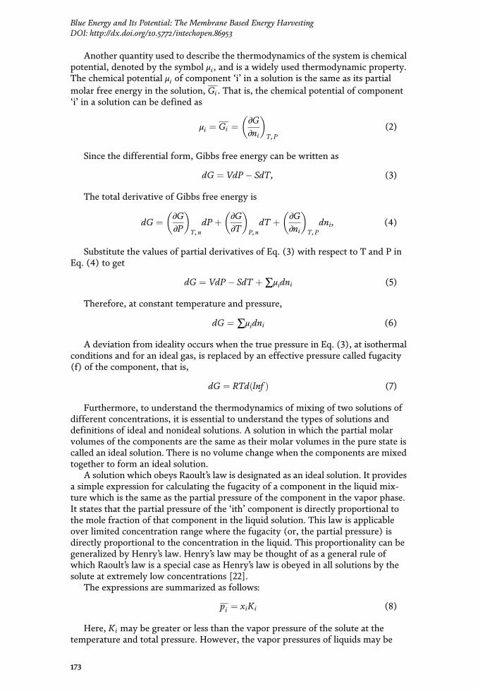

extremely low, so an experimental determination of their fugacity is impractical.Therefore, another function called activity, defined as the ratio of fugacity tofugacity in the standard state of the liquid, may be used. Activity is a ¼ f=f o, wherethe standard state at which fugacity is f o is chosen arbitrarily, but the temperaturein the standard state is the same as the temperature at the given conditions. Thechange in the Gibbs free energy accompanying the process in terms of the activityof the substance is
ΔG ¼ RTlnff o
¼ RTlna (9)
Therefore, for the ‘i’th component, the free energy change is given by
ΔG ¼ RTln f if o¼ RTlnai.
For ideal solutions, the molar property of the solution is simply the summationof the molar properties of the pure components, each weighted according to itsmole fraction. But for nonideal solutions, the estimation of thermodynamic proper-ties will require the addition of a correction term known as the property change ofmixing. Thus, free energy change of mixing of a substance, when it is brought fromits standard state to the solution, can be written as
Gi � G0i ¼ RTln
f if 0
¼ RTlnai (10)
This in terms of its mole fraction can be written as
ΔG ¼ RT∑xilnai (11)
The above equation can be used for ideal solutions by replacing ai with xi.
3. Theoretical potential of osmotic pressure gradient energy
Salinity gradient or osmotic pressure gradient energy is the free energy which isreleased during the mixing of waters with different salt concentrations. The Gibbsfree energy of mixing is the upper limit of extractable energy. The Gibbs free energycalculations will provide an idea of the energetics of mixing, and this can be done byapplying principles of basic thermodynamics. The free energy available frommixing 1 m3 of saltwater and 1 m3 of freshwater can be calculated as
ΔG ¼ GB � GS þ GFWð Þ (12)
where ΔG (J/mol) of mixing is the change in Gibbs energy and GB, GS, and GFWare the Gibbs energies of the resultant brackish water, the feed solution which is aconcentrated salt solution, and the dilute solution (J/mol), respectively. Assumingthe solutions are ideal, the chemical potential (μi) of component i in the solution canbe presented as [9]
μi ¼ μ0i þ viΔpþ RT ln xi þ zij jFΔφ (13)
where μ0i is the molar free energy under standard conditions (J/mol), vi is thespecific volume of component i (m3/mol), Δp is the pressure change compared to
174
Advances in Membrane Technologies
the atmospheric conditions (Pa), R is the gas constant (8.31441 J/mol K),T is theabsolute temperature (K), xi is the molar fraction of the component i, z is thevalence of an ion (equiv./mol), F is the Faraday constant (96,485 C/equiv.), and Δφis the electrical potential difference (volt).
The total amount of energy is determined from the chemical potential differencebefore mixing a concentrated and dilute solution subtracted by the chemical poten-tial after mixing them. It is given by
ΔG ¼ ∑i
Gi,F þ Gi,D �Gi,Bð Þ (14)
ΔG ¼ ∑i
ci,FVFRT ln xi,F þ ci,DVDRT ln xi,D � ci,BVBRT ln xi,Bð Þ (15)
where c is the molar concentration (mol/L) and V is the volume (L).
3.1 Pressure-retarded osmosis system
3.1.1 Principle of pressure-retarded osmosis
A pressure-retarded osmosis plant utilizes osmotic pressure to produce energyfrom mixing freshwater and saltwater. This system involves the interactionbetween two solutions of different salinity which are brought into contact by asemipermeable membrane module (Figure 1). This membrane module allows thesolvent (i.e. water) to permeate and retain the solute (i.e. dissolved salts). Thesemembrane modules may contain spiral-wound or hollow fibre membranes. Itshould have a high water flux and a high salt retention capacity. It results in thetransport of water from the diluted salt solution to the more concentrated saltsolution. Typical membrane performance is in the range of 4–6 W/m2 [23].
The driving force between the solutions is the chemical potential difference inthe saline solutions. The transport of water from the low-pressure diluted solutionto the high-pressure concentrated solution results in pressurization of the volume oftransported water. The osmotic process increases the volumetric flow of high-pressure water. This pressurized volume of transported water is the basis for energytransfer in a PRO plant and can be used to generate electrical power in a turbine.
Figure 1.Energy recovery using a PRO module.
175
Blue Energy and Its Potential: The Membrane Based Energy HarvestingDOI: http://dx.doi.org/10.5772/intechopen.86953

3.1.2 Driving force for pressure-retarded osmosis
In order to model a PRO system, an understanding of the driving forces behindthe transport of ions and water across the membrane which result in a pressurizedvolume of transported water must be made.
The driving force for the permeation of water is a difference in free energybetween the salt and the freshwater side. It can be written as follows:
μi ¼ μ0i þ viΔpþ RT ln xi þ zij jFΔφ (16)
3.1.3 Modeling PRO
Several assumptions have to be made in order to use the above equation tocalculate the free energy difference obtained due to mixing a concentrated and adiluted solution. Feed solutions are assumed to consist of pure sodium chloridesolutions alone. The membrane modules were considered to behave ideally, that is,these were only permeable to water. The process was presumed to take place atconstant temperature and volumetric mixing rate of the concentrated solution tothe diluted solution.
As previously mentioned, the driving force for the permeation of water is adifference in free energy between the salt and the freshwater side across the semi-permeable membrane. Since there is no transport of ions ( zij jFΔφ = 0), no hydro-static pressure is applied at the diluted solution side (Δp = 0), and at equilibriumconditions chemical potentials of water in the concentrated and dilute solutions areequal, Eq. (1) becomes
RT ln xH2O,d ¼ vH2O,cΔπ þ RT ln xH2O,c (17)
Expanding the logarithmic term, ln xH2O = ln 1� 2xH2Oð Þ ≈ 2 ln 1� xH2Oð Þ andputting vH2O,c = v, Eq. (2) becomes
Δπ ¼ 2RTv
ln1� xdð Þ1� xcð Þ (18)
The total amount of energy is determined from the chemical potential differencebefore mixing a concentrated and dilute solution subtracted by the chemical poten-tial after mixing them. It is given by
ΔG ¼ ∑i
Gi, c þGi,d �Gi,bð Þ (19)
ΔG ¼ ∑i
ci, cVcRT ln xi, c þ ci,dVdRT ln xi,d � ci,bVbRT ln xi,bð Þ (20)
The relation obtained in Eq. (3) defines the osmotic pressure difference betweenboth solutions and is the driving force for water transport. The physical significanceof this parameter can be realized in the following manner for designing a PROsystem:
• A hydrostatic pressure when applied at the saltwater side (ΔP, Pa) reduces thedriving force for water transport to Δπ�ΔP.
• The applied hydrostatic pressure difference should be less than the osmoticpressure (ΔP<Δπ).
176
Advances in Membrane Technologies
• This applied hydrostatic pressure should be lesser than the maximum allowablehydrostatic pressure difference over the membrane, which is governed by thestructure of the membrane and its properties.
• The volumetric flow rate of water through the membrane (Q) and thehydrostatic pressure difference (ΔP) can be used for power production by aturbine and generator.
3.2 Membrane selectivity
The performance of the PRO membranes is limited by factors such as concen-tration polarization, reverse salt flux, and membrane fouling. The theoretical cor-relations obtained will have to be corrected in order to accommodate these effects.The goal would be to reduce these factors which would increase the efficiency of themembrane module, thereby increasing the energies of PRO [24].
The water flux ( Jw) and reverse salt flux ( Js) can be defined in terms of themembrane water permeability coefficient A and salt permeability coefficient B:
Jw ¼ A πD,m � πF,m � ΔPð Þ (21)
Js ¼ B cD,m � cF,mð Þ (22)
The term πD,m � πF,mð Þ is called the effective osmotic pressure Δπmð Þ, which islower than the osmotic pressure difference between the draw and feed solutions onthe side of the active layer of the membrane (i.e. Δπm< πD,m � πF,mð ÞÞ. This occursdue to the detrimental effects of external concentration polarization (ECP) in thedraw solution, internal concentration polarization (ICP) within the porous support,and reverse salt flux (Js) across the membrane.
A reduction in the driving force is observed due to concentration polarizationwhich occurs on the feed side and draw side of the membrane active layer. This thenresults in a reduction of the water flux achievable in the process [25]. This phe-nomenon is presented in Figure 2.
As water molecules permeate across the membrane from the feed to the drawsolution, the concentration of rejected solutes builds up on the feed side of themembrane active layer, and the concentration at the draw side of the membraneactive layer gets diluted by the permeating water. A combination of concentration
Figure 2.Schematic representation of the membrane channel cross section.
177
Blue Energy and Its Potential: The Membrane Based Energy HarvestingDOI: http://dx.doi.org/10.5772/intechopen.86953

polarization and a reverse flux from the draw solution to the feed solution results ina significant reduction in the osmotic pressure difference.
The properties of the membrane such as support layer thickness (δ), tortuosity(τ), and porosity εð Þ effect the permeability of water and salt across the membrane.A structural parameter of the support layer (S) is defined to establish a relationbetween these properties:
S ¼ δτ
ε(23)
Decreasing the membrane thickness and the tortuosity and increasing theporosity will result in a diffusion of solutes out of the support layer and into the bulksolution, thereby increasing the osmotic pressure difference.
3.3 Performance indicators
There are various performance indicators which help in quantifying the func-tioning of a PRO process and its economic viability, which are presented in thefollowing sections.
3.3.1 Power density (W)
It is defined as the total amount of power that can be extracted per unit ofmembrane area in the module. It is equal to the product of the volumetric water fluxand the hydraulic pressure difference over the membrane. It can also be written as aratio of the power output and the membrane area [26]:
W ¼ JwΔP ¼ ΔPΔQð ÞAm
¼ A πD,m � πF,m � ΔPð ÞΔP (24)
Upon differentiating the above equation with respect to ΔP, a maximum valueof W can be obtained at ΔP = Δπm/2. Substituting this value for ΔP in Eq. (9) yields
W ¼ AΔπm2
4(25)
The reverse salt flux occurs when ΔP ¼ Δπm.As discussed in the previous section, the phenomenon of internal concentration
polarization, dilute external concentration polarization, and reverse salt flux willhave to be taken into consideration while defining membrane properties and waterflux [27]. As a result, the water flux across the membrane could be calculated as thefollowing using experimentally measurable parameters such as permeability coeffi-cients (A and B) and taking ICP, ECP, and reverse salt flux into consideration:
Jw ¼ πde�Jwkð Þ � πf e
JwSDð Þ
1þ BJw
eJwSDð Þ � e�
Jwkð Þh i� ΔP
8<:
9=; (26)
Similarly, the salt flux relation is given by
Js ¼cDe�
Jwkð Þ � cFe
JwSDð Þ
1þ BJw
eJwSDð Þ � e�
Jwkð Þh i
8<:
9=; (27)
178
Advances in Membrane Technologies
From the above equations, a correlation between membrane characteristics andfluxes of water and salt is obtained. Hence, a lower support layer structural param-eter (S) will result in a higher water flux by reducing internal concentration polar-ization. However, the active layer water permeability cannot simply be increased toimprove performance since, after a certain point, the negative impact of reverse saltflux will outweigh the positive impact of higher water permeability.
3.3.2 Specific energy (SE)
This parameter provides the maximum amount of energy which can beextracted per unit combined volume of draw and feed solution.
It is given by
SE ¼ ΔPΔQQf,o þQd,o
(28)
The above equation may be corrected depending upon the type of process beingexamined, such as an RO-PRO hybrid. The practical value of the maximumextractable energy will differ from the one theoretically obtained. For real systems,lower specific energy than the one theoretically calculated will be obtained. Theevaluation of specific energy consumption over various components of the processsuch as pressure pumps and pretreatment equipment will give an overview of theamount of energy needed to be supplied and the amount being extracted. It wouldthen give a clear indication of the energy extraction efficiency of the designedprocess. Also, capital and operating costs of the process can be determined as it is afunction of the volume of solutions passing through the system and the poweroutput.
3.4 Reverse salt flux selectivity
Another factor which would define the efficiency of the membrane module isthe reverse salt flux selectivity. It is defined as the ratio between the flux of waterand that of salt permeated across the membrane ð Jw=JsÞ. The value of this fractiondetermines whether the preference for water flux to increase will be higher orlower. Besides a higher pumping pressure, there will be additional challenges to theimplementation of PRO with hypersaline sources. The selectivity of membranes willdecrease with higher concentration draw solutions, and performance losses due toincreased reverse salt flux may be very detrimental to the overall efficiency [28].Therefore, a higher reverse salt flux selectivity value favors an increase in transportof water across the membrane as compared to salt [29]. A PRO process is greatlyaffected by reverse salt flux due to the pressure gradient which retards the waterflux across the membrane resulting in a lower value of reverse salt flux selectivity.
3.5 Membrane fouling
One of the biggest disadvantages of this process is the fouling of PRO membranemodules. The membrane characteristics define the degree of fouling of the mem-brane and result in changes in values of power density and specific energy [30].When this system is applied in real situations under seawater feed and brackishdraw solutions, a serious case of biofouling is observed. The formation of an organiclayer on the membrane surface might have a significant negative effect on power
179
Blue Energy and Its Potential: The Membrane Based Energy HarvestingDOI: http://dx.doi.org/10.5772/intechopen.86953

density which may be enhanced due to the presence of cations in the salt solution[31]. Hence, antifouling membranes with suitable characteristics must be synthe-sized which would result in improved specific energies and power densities.
3.6 Technical and economic aspects
3.6.1 Technological advancements
Many technological advancements have been observed in the models of PROplants since the introduction of its concept. A scheme consisting of recycling flowknown as MVDM-R was used to continuously produce the concentrate from brineand distillate water. Electric power is produced in the PRO via the concentratedbrine obtained from MVDM-R, which is used as the draw solution [32]. Severalhybrid technologies utilizing RO-MD-PRO systems in combinations are used. Sev-eral ionic, organic, and inorganic draw solutions have been tested as working fluidsin osmotic heat engines [33]. The efficiency of such draw solutions has been evalu-ated using performance indicators such as PRO peak power density, reverse soluteflux, freshwater flux in MD, overall thermal efficiency, and the tendency of thedraw solution to cause equipment corrosion. Further details on these aspects may beexplored to choose the best technology for energy recovery.
3.6.2 Challenges faced
The energy efficiency of pumps, pressure exchanger, and membranes is veryimportant for determining the energy cost of this ‘blue energy’. The efficiency ofPRO is affected by the permeable property of the membrane. The performanceof the fragile membranes poses the biggest challenge to the commercial applicabilityof this technology. The permeation of the salt across the membrane will decreasethe energy efficiency of the system as a result of the effective osmotic pressure, andfouling of the membrane also will deteriorate the performance of the plant.
Therefore, these challenges indicate the need to develop fouling-resistant andsolute-impermeable membranes with tailored surface properties and membranemodules with improved hydrodynamic mixing which ensure adequate flow.
3.7 Economic aspects
The understanding of various technical aspects of a PRO plant is not sufficient todesign a project plant which would be commercially successful. Therefore, a costanalysis will also have to be done across each unit of the plant [34]. The cost per unitvolume of taking a feed stream from a reservoir and either discharging orregenerating is important as economic considerations could shift the ideal operatingpoint for a PRO process [35]. The economic aspects of PRO depend upon factorssuch as power density. The operating expenditure (OpEx) and capital expenditure(CapEx) of the integrated systems are investigated in suitable cost models to vali-date the economic feasibilities of various combinations of RO-FO-PRO systems.This would assist the engineer to choose the most economically feasible hybridprocess [36]. The use of energy-intensive pretreatments to prevent fouling ofmembranes, such as ultrafiltration, results in a reduction in net-specific energy byPRO. Accordingly, the optimization of pretreatment for PRO is key to the successfulimplementation of PRO. The membrane cost and interest rate are also crucialfactors affecting the economic feasibility of hybrid systems.
180
Advances in Membrane Technologies
4. Reverse electrodialysis system
4.1 Principle
A simplified scheme of reverse electrodialysis stack unit is shown in Figure 3.Generally, this configuration of the membrane separation process is preferably usedto circumvent significant local pressure drop between edges of ion exchange mem-branes (IEMs) to prevent the chances of internal leakages of membranes [37]. Thebasic principle of the RED mechanism depends on the concentration gradientbetween concentrate and diluent which are fed to the stack, and it acts as thedriving force for diffusion of ions across the membrane.
The movement of ions through membrane channels is controlled by its permeateselectivity, i.e. cations through CEM, while anions are rejected. Due to these ionicfluxes across membrane channels, the ionic current is generated through the stackwhich leads to the conversion into electricity at the electrodes. In fact, the role ofthe electrode rinse solution is to restore electroneutrality in external channels bymeans of redox reactions at the electrodes: in this way, the electric continuity of thesystem is ensured, and the generated electric current can be used by an externalload.
4.2 Driving force for reverse electrodialysis
Herein, the concentration gradient between concentrate and diluent across eachmembrane acts as driving force for the process of reverse electrodialysis whichhelps to generate transport ions from concentrate to dilute compartment. Practi-cally, the presence of both counter ions and co-ions in the nonideal membrane isequal to the total brine flux across the membranes as presented in Eq. (1):
JBr, tot xð Þ ¼ JBr,coul xð Þ þ JBr,cit xð Þ (29)
Figure 3.A conceptual schematic of reverse electrodialysis stack unit.
181
Blue Energy and Its Potential: The Membrane Based Energy HarvestingDOI: http://dx.doi.org/10.5772/intechopen.86953

where JBr,coul xð Þ = coulombic or counterion flux represents ion flux in the cur-rent generation and JBr,cit xð Þ = co-ion flux represents a loss of driving force. FurtherEq. (29) can be developed as Eq. (30):
JBr, tot xð Þ ¼ j xð ÞF
þ 2Dδm
cs xð Þ � cd sð Þ½ � (30)
where j is the current density, δm is the IEM thickness, D is the co-ion diffusioncoefficient, F is the Faraday constant, and cs xð Þ and cd xð Þ are the concentration ofconcentrated and dilute salt concentration, respectively.
4.3 Model development
To simplify and develop the model, the following assumptions should beconsidered:
i. The impedance between the stack and load is equal.
ii. The flow between the channels is taken as laminar flow between two infiniteparallel plates.
iii. Electroosmotic flux is considered negligible.
iv. Effects of parasitic currents are negligible.
v. Effect of membrane fouling is negligible.
vi. A salinity gradient from the surface to the depth of the system is assumedlinear.
From the Nernst equation, we get the theoretical voltage, generated due to theion flux across the RED stack:
Vstack ¼ ncellαAEMz�
þ αCEMzþ
� �RgasTF
lnCH
CL
� �(31)
The power applied to the load is then.
Pstack ¼ I2stackRload (32)
Pstack ¼ V2stackRload
Rstack þ Rloadð Þ2 (33)
Pstack ¼ V2stackRload
ncell Rohmic þ RBL þ RΔCð Þ þ Rload½ �2 (34)
where Istack is the current and R is the resistance due to the load, ohmic losses,boundary layer losses, and losses along the channel’s length due to decrease in thedifference of concentration between the flows [38]. These mentioned resistancesare mainly dependent on the membrane and spacer properties, solution concentra-tions, and the specific dimensions of the stack (Figure 4).
The ohmic area resistance rohmic is due to electrical resistance from themembranes and the channels which is as follows:
182
Advances in Membrane Technologies
Aohmic ¼ 11� β
ACEM þ AAEMð Þ þ 1ε2k0=C0
wiHCH
þwiLCL
� �(35)
where β is the masking factor due to the spacer shadow effect on the membrane;A is the area resistance of the CEM and AEM, respectively; wi is the intermembranewidth of the high- and low-concentration channels; ε is the porosity of the channelbetween the membranes; k0 is the electrical conductivity of seawater at STP; and C0
is the reference concentration of seawater.Boundary layer resistance due to concentration polarization across the mem-
brane is given for both spacer-filled channels and profiled membranes [13]:
ABL, spacers ¼ 0:62:tres:wiL
þ 0:05� �
(36)
ABL,profiled ¼ 0:96:tres:wiL
þ 0:35� �
(37)
where tres is the residence time, i.e. quotient of flow velocity, and L is membranelength. Now the resistance due to a decrease in concentration along the membranelength L can be measured by Eq. (10):
AΔC ¼ αAEM þ αCEM2
� � R:Tz:F:j
lnAL
AH
� �(38)
where
AL ¼ 1þ j:tresF:ε:wL:CL=MS
: (39)
AH ¼ 1� j:tresF:ε:wH:CH=MS
(40)
Figure 4.A schematic of membrane orientation.
183
Blue Energy and Its Potential: The Membrane Based Energy HarvestingDOI: http://dx.doi.org/10.5772/intechopen.86953

where current density j is as follows:
j ¼ Vtotal
Astack þ Aload(41)
The pressure drop (Δp) along one channel can be expressed as using the Darcy-Weisbach equation (for laminar flow between two infinite parallel plates) [39]:
Δp ¼ fLdH
ρv2
2¼ 48μLv
d2H
(42)
where dH is the hydraulic diameter.Now the hydraulic diameter for spacer-filled membranes is as follows [40]:
dH ¼ 4ε2 w= þ 1� εð Þ:Svsp (43)
And [40, 41] are for profiled membranes:
dH ¼ 4b:w2bþ 2w
(44)
where Svsp is the ratio of the spacer surface area to its volume and b is the widthbetween the profiled ridges (assumed to be proportional to w).
Pumping loss for the entire stack is.
Ppump ¼ 2:ncell:Q :Kp:Δp (45)
where the volumetric rate is Q:
Q ¼ ε:h:w:v (46)
Since linear salinity profile is assumed, energy (E) required to transport a vol-ume (V) of water can be estimated using Eq. (47):
EV¼ 1
2ρtop � ρbot� �
:g:y (47)
where ρ is the density of the water at the top and bottom, g is the gravitationalacceleration, and y is the vertical distance traversed from top to bottom. Then theconsequent power loss can be estimated by Eq. (48):
Pbuoyant ¼ 0:75ncell:EV:Q (48)
Now the actual power available to provide thrust or power the system can bedetermined from Eq. (49):
Pnet,mod ¼ Pstack � Ppump � Pbuoyant (49)
4.4 Membrane selectivity
In RED, discriminating ion transport is made through ion-selective membranes,i.e. only either anions or cations are allowed to transport based on AEM and CEM
184
Advances in Membrane Technologies
which results in a potential difference. Since the ion exchange membranes are theprincipal element in the RED system, their performance also becomes essentialinefficient energy generation [42]. Many researchers in the literature suggested onion exchange membranes that the presence of multivalent ions has a negative effecton stack voltage and hence on the power density also [43, 44].
Basically, it has been observed that monovalent ion-selective membranes havethe capability to filter monovalent ions from a solution with good efficiency likeseawater and brackish water containing both multivalent and monovalent ions. In acertain moment, such relative permselectivity can be provided by a very thin layeron the surface of conventional membranes that allows the passage of only monova-lent anions while restricting the passage of divalent ions. In addition to providingmonovalent ion selectivity, a membrane modification like this can simultaneouslybe utilized to control biofouling which is a serious problem not only for RED [45]but also for conventional electrodialysis [46, 47].
To estimate the monovalent selectivity of membranes, bulk transport numbersof monovalent and multivalent ions in an aqueous solution have to be determined.To determine monovalent ion selectivity of the membranes, the current (I) can becalculated for the concentration gradient of dCA
dt which is carried by a single ion (A)shown in Eq. (50):
IA ¼ FVdCA
dt(50)
where F is the Faraday constant (96, 485 C-mol�1), V is the volume of thecirculated solution (cm3), C is the concentration (mol/cm3), and t is the time (sec).
The transport no. of certain ion TnA can be expressed as the ratio of IA to thetotal current (I):
TnA ¼ IAI¼ FV dCA
dt
I¼ FV dCA
dt
iA(51)
where I is the current density (mA/cm2) and A is the effective membrane area(cm2). Hence, the relative permselectivity would be as follows:
PsA2A1
¼TnA2=TnA1
cA2=cA1(52)
where TnA1 and TnA2 denote the transport nos. of A1 and A2 ions, while cA1 andcA2 represent the corresponding concentrations, respectively, during the electrodi-alysis in the system [48].
4.5 Technological and economic aspects
RED is a very emerging field of research based on membrane technology forrenewable energy generation through salinity gradient power. In the past fewdecades, numerous research regarding the technological development of REDinclude various key parameters such as process analysis, testing and optimization,stack design, membrane design and development, fouling modeling and simula-tions, hybrid applications, and extensions to energy storage as a flow battery[49, 50]. Furthermore, recently the RED operability has been extended fromrelatively low-saline solutions to high-saline industrial effluents and thermolyticsolutions regenerated in a closed loop [51]. In spite of these such developments and
185
Blue Energy and Its Potential: The Membrane Based Energy HarvestingDOI: http://dx.doi.org/10.5772/intechopen.86953
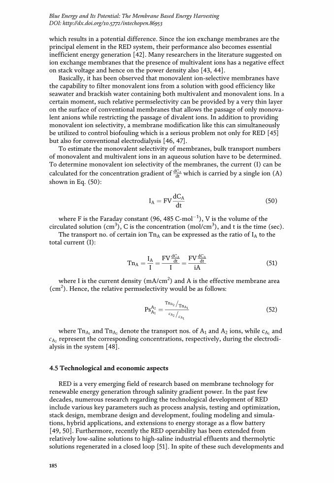
where current density j is as follows:
j ¼ Vtotal
Astack þ Aload(41)
The pressure drop (Δp) along one channel can be expressed as using the Darcy-Weisbach equation (for laminar flow between two infinite parallel plates) [39]:
Δp ¼ fLdH
ρv2
2¼ 48μLv
d2H
(42)
where dH is the hydraulic diameter.Now the hydraulic diameter for spacer-filled membranes is as follows [40]:
dH ¼ 4ε2 w= þ 1� εð Þ:Svsp (43)
And [40, 41] are for profiled membranes:
dH ¼ 4b:w2bþ 2w
(44)
where Svsp is the ratio of the spacer surface area to its volume and b is the widthbetween the profiled ridges (assumed to be proportional to w).
Pumping loss for the entire stack is.
Ppump ¼ 2:ncell:Q :Kp:Δp (45)
where the volumetric rate is Q:
Q ¼ ε:h:w:v (46)
Since linear salinity profile is assumed, energy (E) required to transport a vol-ume (V) of water can be estimated using Eq. (47):
EV¼ 1
2ρtop � ρbot� �
:g:y (47)
where ρ is the density of the water at the top and bottom, g is the gravitationalacceleration, and y is the vertical distance traversed from top to bottom. Then theconsequent power loss can be estimated by Eq. (48):
Pbuoyant ¼ 0:75ncell:EV:Q (48)
Now the actual power available to provide thrust or power the system can bedetermined from Eq. (49):
Pnet,mod ¼ Pstack � Ppump � Pbuoyant (49)
4.4 Membrane selectivity
In RED, discriminating ion transport is made through ion-selective membranes,i.e. only either anions or cations are allowed to transport based on AEM and CEM
184
Advances in Membrane Technologies
which results in a potential difference. Since the ion exchange membranes are theprincipal element in the RED system, their performance also becomes essentialinefficient energy generation [42]. Many researchers in the literature suggested onion exchange membranes that the presence of multivalent ions has a negative effecton stack voltage and hence on the power density also [43, 44].
Basically, it has been observed that monovalent ion-selective membranes havethe capability to filter monovalent ions from a solution with good efficiency likeseawater and brackish water containing both multivalent and monovalent ions. In acertain moment, such relative permselectivity can be provided by a very thin layeron the surface of conventional membranes that allows the passage of only monova-lent anions while restricting the passage of divalent ions. In addition to providingmonovalent ion selectivity, a membrane modification like this can simultaneouslybe utilized to control biofouling which is a serious problem not only for RED [45]but also for conventional electrodialysis [46, 47].
To estimate the monovalent selectivity of membranes, bulk transport numbersof monovalent and multivalent ions in an aqueous solution have to be determined.To determine monovalent ion selectivity of the membranes, the current (I) can becalculated for the concentration gradient of dCA
dt which is carried by a single ion (A)shown in Eq. (50):
IA ¼ FVdCA
dt(50)
where F is the Faraday constant (96, 485 C-mol�1), V is the volume of thecirculated solution (cm3), C is the concentration (mol/cm3), and t is the time (sec).
The transport no. of certain ion TnA can be expressed as the ratio of IA to thetotal current (I):
TnA ¼ IAI¼ FV dCA
dt
I¼ FV dCA
dt
iA(51)
where I is the current density (mA/cm2) and A is the effective membrane area(cm2). Hence, the relative permselectivity would be as follows:
PsA2A1
¼TnA2=TnA1
cA2=cA1(52)
where TnA1 and TnA2 denote the transport nos. of A1 and A2 ions, while cA1 andcA2 represent the corresponding concentrations, respectively, during the electrodi-alysis in the system [48].
4.5 Technological and economic aspects
RED is a very emerging field of research based on membrane technology forrenewable energy generation through salinity gradient power. In the past fewdecades, numerous research regarding the technological development of REDinclude various key parameters such as process analysis, testing and optimization,stack design, membrane design and development, fouling modeling and simula-tions, hybrid applications, and extensions to energy storage as a flow battery[49, 50]. Furthermore, recently the RED operability has been extended fromrelatively low-saline solutions to high-saline industrial effluents and thermolyticsolutions regenerated in a closed loop [51]. In spite of these such developments and
185
Blue Energy and Its Potential: The Membrane Based Energy HarvestingDOI: http://dx.doi.org/10.5772/intechopen.86953

research, there are some noticeable challenges which should be justified in order toturn RED into a viable technology for power production which include membraneproperties, i.e. electrical resistance and permselectivity; fluid dynamics, i.e. stackarrangement and profiled membranes; and stability against membrane fouling dueto the use of saline streams [51]. Therefore, to overcome these current shortcom-ings, advanced technological innovations are required in the design anddevelopment.
Not only the technological development of membrane properties and the REDprocess is necessary, the economic flexibility and viability are also required to dothe overall technology feasible [51]. From investigations, it is found that the currentprice of the membrane is 50 €/m2 and, hence, the process becomes more expensivethan the other renewable energy sources like solar, wind, etc. [52]. Therefore, byreducing this price per square metre by using low-cost materials, the overall elec-tricity cost might drop to 0.18 €/m2 in the near future [52]. Nowadays, hybridsystems are taken as one of the major focuses to increase the feasibility of theprocess using RO, membrane distillation (MD), etc., though they are quite complexbecause the RO system can produce a large volume of brine that can be furtherprocessed to increase the concentration by MD to apply it in RED [53, 54]. Aneconomic breakthrough might be achieved by developing high-performance IEMmaterials and by the use of a low-grade waste heat source to increase the REDoutput power [55].
In the last few decades, a remarkable advancement in RED enactment has beenachieved with electrifying progress in spacers and ion exchange membranes. As anexample the tailor-manufactured IEM showed a power density of 1.27 W/m2 whichwas specially modeled and designed for IEMs in 2012 [56]. Various pioneeringspacer designs and their ion conductivity [57] performances, which are the pillar ofany electrochemical structures, and the use of ion exchange resins [58] can advancethe power density by four times than before. To do the economically feasible REDprocess, membrane availability with low cost is most important, and to meet thischallenge, membranes need to be manufactured rapidly [59]. Moreover, moderntechnology is using mixed metal oxide materials for electrode preparation for low-ering the total cost which uses ruthenium, iridium, etc. being a much low-costmaterial than platinum [60].
5. Conclusion
It is essential to look into a sustainable water-energy nexus which would help inaddressing the ever-growing global demand for energy. The ‘salinity energy’ storedas the difference in salinity between seawater and freshwater is a large-scalerenewable energy source that can be exploited [61]. The application of hybridsystems and energy cogeneration processes such as the tri-combination of reverseosmosis, membrane distillation, and pressure-retarded osmosis processes will leadto an energy-efficient and sustainable solution to the energy demand. Systems thatcan continuously produce both distillate and a very concentrated brine along withenergy production, such as a hybrid PRO-MD, have shown prospects for improvedpower density and water flux. In order to integrate PRO and MD, membranesprovide higher water permeability and salt rejection while minimizing the polari-zation effects.
One of the main hindrances foreseen in the large-scale implementation of mem-brane desalination is the properties of the membrane itself. The semipermeablemembrane should have a good water transport flux and ion selectivity, and themembrane should be resistant to fouling when using natural seawater and river
186
Advances in Membrane Technologies
water. The structural parameter of membranes defines mechanical properties whichwould improve energy consumption and power densities. Higher water permeabil-ity and minimum reverse salt flux with minimum concentration polarization canthen be achieved. Pretreatment of draw solution to the PRO will ensure a reductionin fouling of the membrane. Therefore, future improvements to PRO membranesand draw solutions will improvise the energy recovery of the process. Future scopeof research would include PRO membrane property optimization, PRO draw solu-tions from ionic organic solutions (such as formates and proponents) and alterna-tive inorganic salts (such as calcium, magnesium, and lithium salts), and energyefficiencies in hybrids such as FO-PRO and RO-PRO. Once the disadvantages of theprocess have been accounted for, this osmotic heat engine can be considered as acompetitive renewable energy and energy storage technology.
Reverse electrodialysis is shown to obtain a high energy recovery from mixingseawater and river water. Obtainable energy recovery is more than 80%. Thediscussion has provided a clearer understanding of the process, especiallyconcerning the ohmic stack resistance. Several factors which would govern theefficient evaluation of a stack design have been studied. The proceeding chargetransfer is one such factor which should be taken into account. At each stage ofcharge transfer, the relative contribution of each component to the cell pair resis-tance is different. Estimations of all contributors are based on the apparent charac-teristics as mentioned previously (membrane resistances are assumed to beconstant, i.e. 3 Ω cm2 for each membrane). One of the design issues encountered inthis system is that of the river compartment thickness. Further research into theoptimization of existing technologies and implementation of design principlesbased on sustainability, while taking into account the economic viability of theproposed systems, will ensure the large-scale applicability of such salinity gradientenergy extraction methodologies.
Acknowledgements
Anirban would like to thank the Research Initiation Grant (BPGC/RIG/2017-2018, dt. 01/08/2017) and OPERA award FR/SCM/230117/CHE, dt. 19/08/2017) byBITS Pilani Goa for carrying out the work.
Abbreviations
A = membrane area (m2)μ = molar free energy (J/mol)v = partial molar volumeΔp = static pressure difference compared to standard static pressure (Pa)ΔP = hydrostatic pressure difference between solutions (Pa)R = universal gas constant (J/mol�K)T = temperature (K)z = valence of ions (eq/mol)F = Faraday constant (C/mol)Δφ = electrical potential difference (V)Δπ = osmotic pressure difference (Pa)ΔG = change in Gibbs free energy (J)Δc = change in concentrationG = partial molar free energy in the solutionV = volume (m3)
187
Blue Energy and Its Potential: The Membrane Based Energy HarvestingDOI: http://dx.doi.org/10.5772/intechopen.86953

c = concentration (mol/m3)J = fluxS = structural parameter of the support layerδ = support layer thicknessτ = tortuosityε = porosityW = power densityA = membrane water permeability coefficientB = salt permeability coefficientk = draw mass transfer coefficientQ = volumetric flow rate (m3=s)n = number of molesH = enthalpyS = entropyf = fugacityK = Henry’s constanta = activityD = diffusion coefficientj = current densityR = resistanceL = membrane lengthI = currentP = powerAEM = anion exchange membraneCEM = cation exchange membraneβ = masking factorwi = intermembrane widthk = electrical conductivityt = time (s)α = Chemical activity of ionic speciesd = diameterTn = transport numberPs = permselectivityg = gravitational accelerationy = vertical distance traversed from top to bottomSvsp = ratio of the spacer surface area to its volumeb = width between the profiled ridgesf = friction factorv = velocity of streamw = widthncell = total no. of cellsM = molecular weight (g/mol)Kp = correction factor for the pressure dropSubscriptsi = componentc = concentrated solutionb = brackish solutiond = diluted solutionw = waters = saltm = membraneFW = freshwaterf = feed solution
188
Advances in Membrane Technologies
d = draw solutioncoul = columbic or counterionsBr = brinecit = co-ionstot = total0 = reference pointBL = boundary layerres = residencestack = stackload = loadcell = cellohmic = ohmicH = hydraulicE = energyρ = density of the waterA = component Atop = top of stackbot = bottom of stackH = higher concentrationL = lower concentrationbuoyant = buoyant forcesnet mod = net modified
Author details
Shubham Lanjewar, Anupam Mukherjee, Lubna Muzamil Rehmanand Anirban Roy*Department of Chemical Engineering, BITS-Pilani K. K. Birla Goa Campus,Goa, India
*Address all correspondence to: [email protected]
© 2020TheAuthor(s). Licensee IntechOpen.Distributed under the terms of theCreativeCommonsAttribution -NonCommercial 4.0 License (https://creativecommons.org/licenses/by-nc/4.0/),which permits use, distribution and reproduction fornon-commercial purposes, provided the original is properly cited. –NC
189
Blue Energy and Its Potential: The Membrane Based Energy HarvestingDOI: http://dx.doi.org/10.5772/intechopen.86953

References
[1] Seppala A, Lampinen MJ. On thenon-linearity of osmotic flow.Experimental Thermal and FluidScience. 2004;28:283-296
[2] Loeb S. Production of energy fromconcentrated brines by pressure-retarded osmosis. Journal of MembraneScience. 1976;1:49-63
[3] Gi HJ, Zhang B, Shira G, Uzal N, DouX, Zhanga H, et al. Potential ionexchange membranes and systemperformance in reverse electrodialysisfor power generation: A review. Journalof Membrane Science. 2015;486:71-88
[4] Olsson M, Wick GL, Isaacs JD.Salinity gradient power-utilizing vapor-pressure differences. Science. 1979;206:452-454
[5] Sussman MW, Katchalsky A.Mechanochemical turbine: A new powercycle. Science. 1970;167:45-47
[6] Lagger G, Jensen H, Josserand J,Girault HH. Hydro-voltaic cells. Part 1:Concentration cells. Journal ofElectroanalytical Chemistry. 2003;545:1-6
[7] Logan BE, Elimelech M. Membrane-based processes for sustainable powergeneration using water. Nature. 2012;488(7411):313
[8] Lee S, Juneseok C, Park Y-G, Shon H,Ahn CH, Kim SH. Hybrid desalinationprocesses for beneficial use of reverseosmosis brine: Current status and futureprospects. Desalination. 2019;454:104-111
[9] Cheng ZL, Li X, Chung T-S. Theforward osmosis-pressure retardedosmosis (FO-PRO) hybrid system: Anew process to mitigate membranefouling for sustainable osmotic powergeneration. Journal of MembraneScience. 2018;559:63-74
[10] Cipollina A, Micale G. SustainableEnergy from Salinity Gradient.Woodhead Publishing Series in Energy;United Kingdom: Cambridge; 2016.pp. 1-343
[11] Allison RP. Electrodialysis reversalin water reuse applications.Desalination. 1995;103:11-18
[12] Bevacqua M, Carubia A, CipollinaA, Tamburini A, Tedesco M, Micale G.Performance of a RED system withammonium hydrogencarbonate solutions. Desalinationand Water Treatment. 2016;57:23007-23018
[13] Brauns E. Towards a worldwidesustainable and simultaneous large-scaleproduction of renewable energy andpotable water through salinity gradientpower by combining reversedelectrodialysis and solar power.Desalination. 2008;219:312-323
[14] Pattle R. Production of electricpower by mixing fresh and salt water inthe hydroelectric pile. Nature; 1954;174:660
[15] PAttle RE. Electricity from fresh andsalt water—Without fuel. ChemicalProcess Engineering. 1995;35:351-354
[16] Murphy GW, Matthews RR.Osmionic demineralization. Industrialand Engineering Chemistry. 1958;50:1181-1188
[17] Murphy GW, Matthews RR.Migration in transference cells with andwithout membranes—Applications toosmionic demineralization.Electrochimica Acta. 1967;12:983-998
[18] Weinstein JN, Leitz FB. Electricpower from differences in salinity:The dialytic batter. Science. 1976;191:557-559
190
Advances in Membrane Technologies
[19] Lacey RE. Energy by reverseelectrodialysis. Ocean Engineering.1980;7:1-47
[20] Samland MC. An assessment ofreverse electrodialysis for application tosmall-scale aquatic systems.Massachusetts Institute of Technology,M.Sc. in Mechanical Engineering, U.S.;2018
[21] Pitzer K. Thermodynamics. NewYork: Mc Graw Hill; 1995
[22] Modell M, Tester JW.Thermodynamics and its Application.Upper Saddle River, NJ: Prentice Hall;1997
[23] Gerstandt K, Peinemann KV, Erik S,hagen S, Thorsen T, Holt T. Membraneprocesses in energy supply for anosmotic power plant. Desalination.2008;224(1–3):64-70
[24] He W, Wang Y, Mohammad HS.Energy and thermodynamic analysis ofpower generation using a naturalsalinity gradient based pressure retardedosmosis process. Desalination. 2014;350:86-94
[25] Gordon GT, McCutcheon JR,Menachem E. Internal concentrationpolarization in forward osmosis: Role ofmembrane orientation. Desalination.2006;197(1–3):1-8
[26] Andrea A, Cath TY, Childress AE.Power generation with pressureretarded osmosis: An experimentaland theoretical investigation.Journal of Membrane Science. 2009;343:42-52
[27] Zhang S, Tai-Shung C.Minimizing the instant andaccumulative effects of salt permeabilityto sustain ultrahigh osmotic powerdensity. Environmental Scienceand Technology. 2013;47(17):10085-10092
[28] Bason SY. Ion transport in thepolyamide layer of RO membranes:Composite membranes and free-standing films. Journal of MembraneScience. 2011;367:119-126
[29] She Q, Xue J, Chuyang YT. Osmoticpower production from salinity gradientresource by pressure retarded osmosis:Effects of operating conditions andreverse solute diffusion. Journal ofMembrane Science. 2012;401:262-273
[30] Bar-Zeev E, Perreault F, Straub AP,Elimelech M. Impaired performance ofpressure-retarded osmosis due toirreversible biofouling. EnvironmentalScience and Technology. 2015;49:13050-13058
[31] She Q, Wong YKW, Zhao S, TangCY. Organic fouling in pressure retardedosmosis: Experiments, mechanisms andimplications. Journal of MembraneScience. 2013;428:181-189
[32] Jung-Gil L, Young-Deuk K, Sung-Min S, Baek-Gyu I, Woo-Seung K.Numerical study of a hybrid multi-stagevacuum membrane distillation andpressure-retarded osmosis system.Desalination. 2015;363:82-91
[33] Akther N, Sodiq A, Giwa A, Daer S,Arafat HA, Hasan SW. Recentadvancements in forward osmosisdesalination: A review. ChemicalEngineering Journal. 2015;281:502-522
[34] Tai-Shung C, Wan CF. Techno-economic evaluation of various RO+PRO and RO+ FO integrated processes.Applied Energy. 2018;212:1038-1050
[35] Reimund KK, McCutcheon JR,Wilson AD. Thermodynamic analysis ofenergy density in pressure retardedosmosis: The impact of solution volumesand costs. Journal of Membrane Science.2015;487:240-248
[36] Youngkwon C, Saravanamuthu V,Sangho L. Evaluation of fouling
191
Blue Energy and Its Potential: The Membrane Based Energy HarvestingDOI: http://dx.doi.org/10.5772/intechopen.86953

potential and power density in pressureretarded osmosis (PRO) by foulingindex. Desalination. 2016;389:215-223
[37] Strathmann A. Ion-exchangemembrane separation processes.Membrane Science and Technology.2004;9:1-348
[38] Vermaas DA, Guler E, Saakes M,Nijmeijer K. Theoretical power densityfrom salinity gradients using reverseelectrodialysis. Energy Procedia. 2012;20:170-184
[39] Munson BR, Okiishi TH, HuebschWW, Rothmayer AP. Fundamentals ofFluid Mechanics. 7th Ed. Hoboken: JohnWiley & Sons, Inc; 2013
[40] Miquel A, Schock G. Mass transferand pressure loss in spiral woundmodules. Desalination. 1987;64:339
[41] Costa ARD, Fane AG, Wiley DE.Spacer characterization and pressuredrop modelling in spacer-filled channelsfor ultrafiltration. Journal of MembraneScience. 1994;87:79-98
[42] Guler E, Baak WV, Saakes M,Nijmeijer K. Monovalent-ion-selectivemembranes for reverse electrodialysis.Journal of Membrane Science. 2014;455:254-270
[43] Post JW, Hamelers HVM, BuismanCJN. Influence of multivalent ions onpower production from mixing salts andfresh water with a reverseelectrodialysis system. Journal ofMembrane Science. 2009;330:65-72
[44] Vermaas D, Veerman J, Saakes M,Nijmeijer K. Influence of multivalentions on renewable energy generation inreverse electrodialysis. Energy andEnvironmental Science. 2014
[45] Vermaas DA, Kunteng D, Saakes M,Nijmeijer K. Fouling in reverseelectrodialysis under natural
conditions. Water Research. 2013;47:1289-1298
[46] Lee HJ, Moon SH, Tsai SP. Effects ofpulsed electric fields on membranefouling in electrodialysis of NaClsolution containing humate. Separationand Purification Technology. 2002;27:89-95
[47] Mulyati S, Takagi R, Fujii A,Ohmukai Y, Matsuyama H.Simultaneous improvement of themonovalent anion selectivity andantifouling properties of an anionexchange membrane in anelectrodialysis process, usingpolyelectrolyte multilayer deposition.Journal of Membrane Science. 2013;431:113-120
[48] Sata T. Studies on anion exchangemembranes having permselectivity forspecific anions in electrodialysis—Effectof hydrophilicity of anion exchangemembranes on permselectivity ofanions. Journal of Membrane Science.2000;167:1-31
[49] Kingsbury RS, Chu K, Coronell O.Energy storage by reversibleelectrodialysis: The concentrationbattery. Journal of Membrane Science.2015;495:502-516
[50] Egmond WJV, Saakes M, Porada S,Meuwissen T, Buisman CJN, HamelersHVM. The concentration gradient flowbattery as electricity storage system:Technology potential and energydissipation. Journal of Power Sources.2016;325:129-139
[51] Tufa RA, Pawlowski S, Veerman J,Bouzek K, Fontananova E. Progress andprospects in reverse electrodialysis forsalinity gradient energy conversion andstorage. Applied Energy. 2018;225:290-331
[52] Daniilidis A, Herber R, VermaasDA. Upscale potential and financial
192
Advances in Membrane Technologies
feasibility of a reverse electrodialysispower plant. Journal of Applied Energy.2014;119:257-265
[53] Jia Z, Wang B, Song S, Fan Y. Blueenergy: Current technologies forsustainable power generation fromwater salinity gradient. Renewable andSustainable Energy Reviews. 2014;31:91-100
[54] Andrjesdóttir Ó, Ong CL, Nabavi M,Paredes S, Khalil ASG, Michel B, et al.An experimentally optimized model forheat and mass transfer in direct contactmembrane distillation. InternationalJournal of Heat and Mass Transfer.2013;66:855-867
[55] IRENA-OES. Salinity GradientEnergy Technology Brief. InternationalRenewable Energy Agency – OceanEnergy Systems; 2014, p. 26
[56] Guler E, Zhang Y, Saakes M,Nijmeijer K. Tailor-made anion-exchange membranes for salinitygradient power generation. Journal ofMembrane Science. 2014;460:139-147
[57] Dlugolecki P, Dabrowska J,Nijmeijer K, Wessling M. Ionconductive spacers for increased powergeneration in reverse electrodialysis.Journal of Membrane Science. 2010;347:101-107
[58] Zhang B, Gao H, Chen Y. Enhancedionic conductivity and power generationusing ion-exchange resin beds in areverse-electrodialysis stack.Environmental Science and Technology.2015;49:14717-14724
[59] Post JW. Blue Energy: ElectricityProduction from Salinity Gradient byReverse Electrodialysis. Wageningen:Wageningen University; 2009
[60] Veerman J, Saakes M, Metz SJ,Harmsen GJ. Reverse electrodialysis:Evaluation of suitable electrode systems.
Journal of Applied Electrochemistry.2010;40:1461-1474
193
Blue Energy and Its Potential: The Membrane Based Energy HarvestingDOI: http://dx.doi.org/10.5772/intechopen.86953

195
Chapter 9
Electrokinetic Membrane BioreactorsMaryam Amini, Eltayeb Mohamedelhassan and Baoqiang Liao
Abstract
The subject of electrokinetics has received considerable interests in the field of membrane bioreactors (MBRs) in recent years. Electrokinetic transport mechanism and associated reactions have wide applications in separations and MBRs. The success of electrokinetic-enhanced separations would highly depend on the study of its conceptions, perhaps leading to opening vast research need. It is also conceiv-able that the theoretical study of electrokinetic phenomena, especially in the MBRs, indeed leads to profound success in the bioreactor research, design, and operations. This chapter is aiming to overcome the enigma in this field of research and make the fundamental concepts and recent advances readily accessible to researchers and practitioners in membrane technologies.
Keywords: membrane bioreactor, electrokinetics, wastewater treatment, fouling, design
1. Introduction
1.1 Membrane bioreactors
Utilizing membrane technology in the conventional activated sludge treat-ment process led to the development of membrane bioreactor (MBR) technology. Membrane improves the process by retaining the suspended solid and increasing the efficiency of the process. The most commonly used types of the membranes are ultrafiltration (UF) and microfiltration (MF) with pore sizes ranging from 0.05 to 0.4 𝜇𝜇m , although other kinds of membranes like reverse osmosis (RO) and forward osmosis (FO) are also being investigated for this process. MBRs showed a high nutrient removal, complete biomass retention, and high quality of treated effluent [1]. MBR technology has been widely used in full-scale plants for municipal and industrial wastewater treatments. Compared to the conventional wastewater treatment plants, MBR showed an easier operation and a lower footprint. Based on the abovementioned advantages, the study of this valuable technology can lead to further developments.
1.2 Status of MBR research
MBR was first introduced commercially in the 1960s by Dorr-Oliver by com-bining the UF membrane with the conventional activated sludge process [2].

Advances in Membrane Technologies
196
The development continued by changing the membranes, such as using ceramic membrane in the mid-1990s, followed by increasing the capacity of this technology. The revolution of the MBR technology occurred in the late 1980s and 1990s by the introduction of submerged membranes in bioreactors with the use of aeration for membrane fouling control, which significantly reduces the energy consumption of MBRs [3, 4]. With a compound annual growth rate (CAGR) of 9.5–12% for MBR before 2013 and 12.8% for the period of 2014–2019, more implementation of MBRs has been expected [2]. With the growth of the MBR industries, the factor of energy cost unavoidably becomes the center of the researcher’s attention recently.
During the last decades, the growth rate of the membrane’s costs enforces scientists to study about the improvement of the membrane properties in order to overcome its bottleneck. Among all researches in the field of MBRs done until now, fouling mitigation was the most dominant research topic [5].
1.3 Challenges and opportunities
Due to the high cost and biomass separation issues of the conventional treatment processes, MBR was developed to overcome the bottlenecks of the conventional processes. The general advantages of MBR technology over the conventional pro-cesses are high effluent quality, low sludge production, easy construction, Small operational volume needed (due to the combination of the membrane filtration and biological treatment), low energy consumption, and low cost [6]. In treatment processes such as flat bioreactor and activated sludge, microalgae can be washed out which causes further cost to cultivate and increase the microalgae population [7]. Therefore, the presence of the membrane filtration in MBR technology helps this process to prevent the washout issue. Despite the fact that the MBR technology has been widely used for municipal and industrial wastewater treatment in full-scale plants, membrane fouling is a major challenge that hinders a wide application of MBRs [6]. The fouling of membranes in MBRs has received much attention as a result of the major role of the membrane’s life span in the performance of MBRs [8, 9]. As MBR has a growing market for municipal and industrial implementa-tion, more research has been pursued to overcome the operational challenges from fouling. Electrokinetically assisted fouling control of MBRs is one of the novel techniques that will be discussed in this chapter.
2. Electrokinetic phenomena
2.1 Electrokinetic transport mechanism
Electrokinetic phenomena have broad applications in the field of separation, surface properties, and microchannel. Electrokinetics in membrane technology uses alternating-current (AC) or direct-current (DC) electric fields for fouling control and process intensification. As defined by Reuss in 1809, electrokinetics is a relative move-ment of liquid and solid particles in an applied electric field [10]. In the presence of the electric field, charged particles will move toward the surface with the opposite charge.
Among different electrokinetic phenomena, electrophoresis (EP), electroosmo-sis (EO), and dielectrophoresis (DEP) are the three primary transport mechanisms affiliated with membrane technology. The schematic illustration of these electroki-netic phenomena is shown in Figure 1.
Electrophoresis (EP), a phenomenon in which charged particles and ions move through the liquid toward the electrode by a DC electric field, was first introduced by Reuss in 1807 [10]. Negatively charged ions and particles will move toward the
197
Electrokinetic Membrane BioreactorsDOI: http://dx.doi.org/10.5772/intechopen.86955
anode, while positive ions and particles travel toward the cathode in the presence of the electric field. One of the main applications of the EP is measuring the surface potential of particles [12].
In a similar manner, dielectrophoresis (DEP) is the movement of ions and charged particles in an aqueous medium. The difference between EP and DEP is the type of applied electric field as DEP transport is generated by AC electric field, whereas the movement of particles and ions by EP is only in the direction of the oppositely charged electrode. The variation of the magnitude and direction of AC electric field causes negative and positive DEP movement.
Considering a particle in a medium with a relatively lower or higher permittivity compared to that of the surrounding medium, when the particle has a positive rela-tive permittivity, it will move toward the strong electric field. This dielectrophoretic motion is called positive DEP. However, when the surrounding medium has higher permittivity compared to the particle, negative DEP will happen, and particles will be repelled to the side of the weak electric field. The schematic figure of these stimuli is presented in Figure 2.
When an external electric field causes the fluid, such as water, to move through the solid surface, e.g., membrane, the electroosmosis (EO) stimuli will happen. In this case, fluid moves toward the anode or cathode which is shown in Figure 1b.
Table 1 provides a comparative study on the abovementioned electrokinetic phenomena. A comprehensive understanding of these movements helps a better prediction of the performance of the applied electric field in the MBR technology.
Figure 1. The concept of electrokinetic phenomena in MBR. (a) Electrophoresis, (b) electroosmosis, and (c) dielectrophoresis (modified from M.B. Ensano et al. [11]).
Figure 2. Two different dielectrophoretic movements: (a) negative DEP and (b) positive DEP (redrawn after Hawari et al. [13]).

Advances in Membrane Technologies
198
Proc
esse
sEP
DEP
EO
Maj
or m
echa
nism
Mov
emen
t of t
he ch
arge
d pa
rtic
les/
ions
Mov
emen
t of t
he ch
arge
d pa
rtic
les/
ions
Mov
emen
t of t
he fl
uid
Disa
dvan
tage
s/ad
vant
ages
• N
eeds
to u
se c
orro
sion
resi
stan
ce
elec
trod
es [1
4]
• N
eeds
PH
mod
ifica
tion
[15]
• Th
e ris
k of
shor
t circ
uit [
15, 1
6]
• Po
ssib
ility
of p
rodu
ctio
n of
toxi
c by
prod
uct [
14]
• Jo
ule h
eatin
g ge
nera
ted
by e
lect
ric f
ield
-eff
ect p
artic
le m
ovem
ent [
15] a
nd
prop
ertie
s of t
he fe
ed [1
6]
• H
ighe
r par
ticle
spee
d co
mpa
red
to E
P [1
7]
• Jo
ule h
eatin
g ge
nera
ted
by e
lect
ric
field
-eff
ect p
artic
le m
ovem
ent [
15, 1
8]
and
prop
ertie
s of t
he fe
ed [1
6, 18
]
App
licat
ions
• Su
rfac
e pot
entia
l and
stre
amin
g po
tent
ial [
12]
• Pr
otei
n se
para
tion
[19,
20]
• G
as se
nsor
s and
det
ectio
n in
stru
men
ts [2
1, 2
2]
• Se
para
tion
of th
e min
eral
s [23
]
• D
rain
por
ous m
edia
[24,
25]
• M
easu
ring
surf
ace c
harg
e of t
he
poro
us m
edia
[26]
• Sl
udge
dew
ater
ing
[27]
Tabl
e 1.
A
com
para
tive s
tudy
of t
he el
ectr
okin
etic
phe
nom
ena.
199
Electrokinetic Membrane BioreactorsDOI: http://dx.doi.org/10.5772/intechopen.86955
2.2 Electrolysis reactions and pH gradient
The chemical properties of the solution affect its electrochemical properties. The chemical dissolution of the electrodes, anode, and cathode and therefore the perfor-mance of a coupled electrokinetic membrane bioreactor (Ek-MBR) are influenced by the pH. With the variation of pH, the coagulation ability of the released ions is different. The released ions from the electrodes will react with the H + or OH − under pH range of acidic (pH < 5 ) and alkaline (pH > 9 ) conditions. For example, at highly alkaline pH, the prominent ions released from the Al anode are Al (OH) 4 − which has a poor coagulation ability. The optimal range of pH considering the coagulation ability is between 5 and 8.
Applied electric field to the metal in an electrolyte solution causes oxidation or reduction of the metals. During oxidation or reduction, ions are released into the solution. The ions can further change the electrochemical properties of the Ek-MBR. The use of metals such as iron or aluminum produces ions which can react as the coagulant in the solution and further decrease the fouling of the membrane. The mechanisms of the reactions at the anode and cathode are:
Anode
M → M m+ + m e − (1)
In the solution
M m+ + m H 2 O → M (OH) m + m H + (2)
Cathode
2 H 2 O + 2 e + → H 2 + 2O H − (3)
where M is metal, M m+ is a metal ion, and M (OH) m is metal hydroxides which react as the coagulants.
The hydroxide ion, released around the cathode, leads to pH increment and alters communal behavior and the sludge properties. The pH range higher than 9 and lower than 5 is not suitable for the microorganisms [28]. Hence, the optimal pH range should be considered as a main factor in the performance of Ek-MBRs.
M (OH) m can neutralize the electrostatic charge of the foulants. Therefore, foulants can be gathered and form a big-size pollutant named flocs. With further agglomera-tion, heavier flocs, which have a lower traveling velocity to membrane surfaces, can be settled by gravity. This active anode process is termed electrocoagulation, usually examined by iron (Fe) and aluminum (Al). The rate and the chemical properties of the released metal ions showed different effects on the microbial community [29]. The rate of released metal ions is a dependent parameter to both the applied electric field and the nature of the electrode. The Faraday’s law (Eq. (4)) describes this relation [30, 31]:
n M m+ = I. t ____ F. m (4)
where n M m+ is the mole of the released metal ion, m is the number of the electrons in the reaction, I is the electric current (A), t is the loading time of the electricity(s), and F is Faraday’s constant which is 96,485 (C/mol). As it is shown by Eq. (4), the electric current determines the number of anodic ions released into the solution. Uncontrolled amount of the released ions in the solution not only increases the energy cost, but it also generates extra heat which can inhibit the nutrient removal’s efficiency [32–34]. Determining the released amount of ions, chemical reaction, and pH control is hence vital for the fouling control.

Advances in Membrane Technologies
200
2.3 Electrical potential at solid–liquid interface
Electrical potential at the solid–liquid interface is termed zeta potential [35]. The zeta potential can be determined by electrophoretic measurement and is an indicator of the surface charge. The value of the zeta potential directly influences the rate, direction, and distance of travel of water, ions, and charged particles in an electrokinetic process. Considering a layer near the charged particle or membrane, a stationary layer around the charged medium will be created with an opposite charge. The area with dispersed charged particles, where it has a distance from the charged surface, is called dispersion medium, indicating the potential differences between the surface and the dispersed layer (i.e., the zeta potential). The flocculating degree of the colloids is evaluated by zeta potential. The higher the zeta potential, the higher stability of the colloids is and the higher resistance to aggregation. Zeta potential also is associated with membrane fouling. Zeta potential as an indicator of the electrical proper-ties of the membrane represents the tendency of the ions to be adsorbed by the electrostatic forces. It also reveals the amount of electric surface charges that interact with their surrounding [36]. Hence, the zeta potential is an important parameter in controlling the fouling phenomenon.
The streaming potential is a method that can measure the zeta potential. By add-ing electric field across the medium, particles will move toward the electrodes with opposite charge. The velocity or rate of their movement is a proportional parameter to the magnitude of the zeta potential. By measuring the velocity and using theo-ries, scientists could measure the zeta potential of the charged surface.
3. Coupled electrokinetic membrane bioreactor (Ek-MBR)
3.1 General principles
The study on fouling of the membrane in MBRs revealed that activated sludge and some foulants are charged particles. This finding along with the application of electrostatic movement leads to a combination of electrokinetic with the existing MBRs and development of the electrically assisted MBRs (e.g., Ek-MBR). Electric field also improved the membrane permeability. With inserting a cathode and anode in the MBR, the charged particle and also the liquid will move due to the produced electrokinetic phenomena. Hence, applying electric field leads to the control of the movement and deposition of the foulants.
The application of electrostatic force and electrophoretic movement in the membrane fouling abatement goes back to 50 years ago. Figure 3 addressed the classification of Ek-MBR using electrokinetic phenomena either by physical or simultaneous physical and chemical movement.
Physical movement by electric current, including EP, DEP, and EO, has been used for different applications of MBRs. This movement caused by electric field utilizes electrostatic force for repelling the foulants from the membrane. While all of them use electrostatic force, they have different properties that make them special and suitable for different utilizations. In some Ek-MBRs, the metal used for electrodes along with the electrode configuration causes chemical reactions around the electrodes. Due to the ions released around the electrodes and the chemical reactions in the fluid caused by the electric field, both chemical reac-tion and physical movements help fouling mitigation of the membrane. This combination of phenomena, physicochemical phenomena, is referred to as electrocoagulation.
201
Electrokinetic Membrane BioreactorsDOI: http://dx.doi.org/10.5772/intechopen.86955
3.2 Design and operation of Ek-MBR
Due to the lack of appropriate design standards of Ek-MBR, it suffers from a high specific energy demand for the large-scale applications [2]. However, Ek-MBRs are recognized for the high quality of products and are easy to operate [37]. Therefore, the advantages of this technology brought about improved design for further developments.
3.2.1 Electrodes
The electrodes, as the main part of the electric field which are in contact with the sludge, are of interest of many studies. The material and the place where they are arranged can change the property of the electrokinetic movements and the efficiency of Ek-MBR. Eq. (5) shows the dependency of the strength of the electric field to the applied voltage and the distance between electrodes:
E = V __ d (5)
where E is the electric field due to voltage gradient between anode and cathode (V/cm), V is the electric voltage (V), and d is the distance between electrodes (cm).
As described by Eq. (5), the arrangement of the electrodes and the applied potential difference greatly affect the performance of the Ek-MBR. Studies revealed that the influence of electrode materials in Ek-MBRs should be considered. Al and Fe are the most common metals for Ek-MBRs; although some metal ions such as aluminum ions and iron ions can be involved in the bacterial growth, some higher concentration of the metal ions can have inhibitory consequences for microbial growth [38, 39]. Table 2 shows the comparative characteristics of these two metals.
The electrode configuration is of importance due to its influence on the electric distribution. In the case of submerged Ek-MBR, the electrodes should be designed in a way that it does not interfere with the hydrodynamic properties of the solution. Also, the most effective design for producing a uniform distribution with a lower cost and less effect on the membrane’s life span should be considered. Some of the membrane materials are sensitive to the electric field. Moreover, the produced heat can further affect the membrane’s efficiency.
In most Ek-MBRs, the membrane is placed between the electrodes. Therefore, the effective distance between electrodes can provide enough space for the flocs and the air to move freely. Besides, the oxidation or acidic effect on the microbial com-munity should be considered for the proper distance between the electrodes [29].
Figure 3. Classifications of the Ek-MBR based on electrokinetic phenomena.

Advances in Membrane Technologies
202
Figure 4. Electro-cell configuration. (a) Electrode configuration in Ek-MBR and (b) membrane-electrode filtration cell assembly (redrawn after Hawari et al. [13]).
The corrosion of the electrodes and high risk of human electric shock led to developing a new configuration of the electrodes inside the membrane module. In order to overcome this bottleneck, using insulated electrodes with AC electric field was proposed.
The integrated configuration method is usually applied with the AC [16]. The schematic picture of this configuration is shown in Figure 4.
As it is depicted by Figure 4, the small distance between electrodes is designed in order to achieve high dielectric force. This configuration generally is designed for the DEP-assisted MBR. To attain a high electric potential and dielectric force by the minimal electric current, the electrodes are designed with the small distance. Based on Eq. (6) the DEP force for cylindrical electrode will increase with decreasing distance between electrodes:
∇ |E | 2 = − 2 U M 2 _______ r 3 (ln r 1 __ r 2 )
2 (6)
where U M is the voltage across medium, r is the distance between particle and electrode, r 1 is the radius of central electrode, and r 2 is the characteristic length of electrode configuration [13, 16, 40].
The presence of more than two electrodes was also investigated for the seawater treatment within an electrokinetic cell without the presence of the membrane as seen in Figure 5. However, this configuration can be a base study for further use in MBRs.
The cathode in the EP-MBRs is close to the membrane, and even it can be a conductive membrane which acts as a cathode. The conductive membrane was introduced to both simplify the design of the EP-MBRs and mitigate the membrane fouling. The schematic diagrams of Ek-MBRs with a conductive membrane are shown in Figure 6.
Iron Aluminum
Lower price Higher price
Lower toxicity Higher toxicity
Lower surface area and adsorption of soluble compound
Higher surface area and adsorption of soluble compound [11]
Table 2. Relative comparison of anode made of iron and aluminum.
203
Electrokinetic Membrane BioreactorsDOI: http://dx.doi.org/10.5772/intechopen.86955
3.2.2 Current supply
Abroad with the development of Ek-MBR, the role of the applied electric field on the Ek-MBR performance has been studied by researchers. Significant con-sideration has been made on the fouling suppression caused by applied external electric field with both alternative current (AC) and direct current (DC). Recently, the effect of the applied electric field on the microbial community is also considered in order to shed light on the metabolism of the microorganisms at the presence of either AC or DC electric field. The use of potential energy of both wastewater and organic compound of the waste and converting this chemi-cal energy are an in situ utilization of potential energy. This integrated process is called microbial fuel cell (MFC). To sum up, the electric field provided by either
Figure 5. Electrode configurations in the electrokinetic batch cells: (a) anode–cathode, (b) anode–cathode–cathode–anode, and (c) cylindrical (redrawn after Abdulkarem et al. [41]).
Figure 6. Electrode configurations with the conductive membrane.

Advances in Membrane Technologies
204
AC, DC, or chemical energy of the feed, which is a mostly organic compound, showed different processes which are developed due to their importance in the field of the Ek-MBR, and we will discuss them in this section.
3.2.3 Direct current
The use of direct current for improving membrane fouling and changing the prop-erties of the sludge attracts considerable attention [42]. One of the main concerns with applying direct electric field is the cost. The other major concern is about the corrosion of the oxidation of the electrodes due to oxidation caused by direct current. In order to overcome these concerns, intermittent direct current was introduced.
3.2.4 Intermittent direct current
On and off electric field or intermittent electric field introduced to maintain the pH level recommended for the microorganism [28]. In order to examine the effect of the intermittent electric field on the performance and the fouling of the mem-brane, the permeate flux of the membrane during the process as well as the organic compound of the effluent should be measured. On and off period of 1990s for UF membrane revealed that the flux can be recovered during on period. However, the flux declined in the off period [43]. This recovery suggested that in order to reduce the energy cost of the Ek-MBRs with the same efficiency, the suitable intermittent current can be an option for this process. Further investigation for desired electric voltage and intermittence of the exposure time of the DC field admitted that a volt-age gradient of 1 V/cm and a mode of 15 min on/45 min off of DC supply were the best mode for maintaining pH level between 5 and 9 for the submerged MBRs [29]. This mode led to 16.3% reduction of the fouling rate of the membrane. Therefore, this mode became a preferred mode for the following studies.
3.2.5 Alternative current
The heat generated by direct current followed by changing properties of the feed, sludge, and also hydrolysis of water in aqueous solution with a high conductivity as 1 mS/cm led to the development of another method which uses alternative current for fouling suppression [44]. The use of alternative electric field along with DC electric field has been studied in recent years [45–48]. The lower cost of the alternative elec-tric current compared with the direct current encouraged researchers to investigate this process as well. This process was first studied in the lab scale without the mem-brane but with further development on its application in the membrane area. The main concept of the phenomena which happened in this situation is defined by DEP.
3.2.6 Aeration
Sustaining microbial community in MBR is a vital issue in MBR technology. In order to provide oxygen for biomass, keeping activated sludge in suspension and fouling suppression aeration technique have been developed. The shear stress provided by moving bubbles around the surface of the membrane has a critical role in fouling control. However, the cost of aeration or air scouring in MBR was about 50% of the total operation cost. This led to the design optimization of the aeration, including the aeration rate, bubble size, and aeration modes [5].
Intermittent aeration mode was one of the proposed modes to decreasing the energy cost. Fan and Zhou investigated the interrelation between aeration rate and fouling of the membrane. They observed that cyclic aeration (10 s on and 10 s off) reduced the
205
Electrokinetic Membrane BioreactorsDOI: http://dx.doi.org/10.5772/intechopen.86955
cost of energy to 50% while showing a similar fouling rate [49]. The studies of large-scale MBRs stablished the influence of the aeration on the improved performance of the MBRs [50]. Both manual aeration and automatic aeration enhance nutrient removal, fouling control, and energy saving. To sum up, the main design studies in this field are focused on the aeration rate that had been optimized for different processes.
3.3 Applications of Ek-MBR
Membrane bioreactor (MBR) technology is a mature technology and has been widely used both in municipal and industrial wastewater treatment. However, membrane fouling is a major challenge that limits the wide application of MBR technology. By integrating the electricity with the MBRs, new approaches for electrically enhanced fouling control have been created, and electrically enhanced process performance has been achieved. With the assistance of the electric field and improved fouling mitigation and process performance, Ek-MBR has become more favorable for both municipal and industrial wastewater treatment.
Examples on the application of the Ek-MBR include the oily wastewater treat-ment [51], nutrient removal [52, 53], removal of heavy metals [54], and organic compound removal [55]. Negative DEP usually is favorable to biological wastewater reactors. The particles in wastewater generally have lower permittivity than the medium. Therefore, it is considered suitable for wastewater treatment. Ek-MBR with the conductive membranes has been researched for yeast suspension [56, 57] and wastewater applications [58] as well.
One example on the electrically enhanced performance of Ek-MBR is a simul-taneous biodegradation, electrocoagulation, electro-sedimentation, and filtration to reduce membrane fouling and improve COD and nutrient (P) removal [59]. Another example is the integration of microbial fuel cell (MFC) with the MBR technology for bioelectricity generation [60]. Traditionally, the MFC technology is used for bioelectricity generation and characterized with poor effluent quality, due to the limited biomass in MFC. By integrating the MFC and the MBR technology, a synergy of the advantages of both MFC and MBR can be achieved simultane-ously and increase the biomass concentration significantly for biodegradation. Furthermore, it can overcome the disadvantages of both technologies. Thus, the MFC-MBR technology can purify wastewater and generate electricity at the same time with a high efficiency.
4. Conclusion
Given the advantages of the MBR in this chapter, it is quite predictable that this fast-growing technology improves its performance in the case of permeability and energy costs. As the fouling is the major problem with MBRs, the Ek-MBR was proposed that showed better performance. However, further development in design parameters of an Ek-MBR such as electrode configuration and material, aeration, and current supply can inevitably enhance the cost and performance efficiency of this valuable technology. On the basis of the points mentioned above, it would seem that the Ek-MBR can be scaled up for the industrial applications.
Acknowledgements
The authors thank the Natural Sciences and Engineering Research Council of Canada (NSERC) for financial support.

Advances in Membrane Technologies
206
Author details
Maryam Amini1,2, Eltayeb Mohamedelhassan1* and Baoqiang Liao2
1 Department of Civil Engineering, Lakehead University, Thunder Bay, ON, Canada
2 Department of Chemical Engineering, Lakehead University, Thunder Bay, ON, Canada
*Address all correspondence to: [email protected]
Nomenclature
AC alternative currentDC direct currentDEP dielectrophoresisEk-MBR electrokinetic membrane bioreactorEO electroosmosisEP electrophoresisEP-MBR electrophoretic membrane bioreactorFO forward osmosisMBR membrane bioreactorMFC microbial fuel cellMF microfiltrationRO reverse osmosisUF ultrafiltration
© 2020 The Author(s). Licensee IntechOpen. Distributed under the terms of the Creative Commons Attribution - NonCommercial 4.0 License (https://creativecommons.org/licenses/by-nc/4.0/), which permits use, distribution and reproduction for non-commercial purposes, provided the original is properly cited.
207
Electrokinetic Membrane BioreactorsDOI: http://dx.doi.org/10.5772/intechopen.86955
[1] Zodrow K, Brunet L, Mahendra S, Li D, Zhang A, Li Q , et al. Polysulfone ultrafiltration membranes impregnated with silver nanoparticles show improved biofouling resistance and virus removal. Water Research. 2009;43(3):715-723. DOI: :10.1016/j.watres.2008.11.014
[2] Judd S. The MBR Book: Principles and Applications of Membrane Bioreactors for Water and Wastewater Treatment. Elsevier; 2010. 344 p. DOI: 10.1016/B978-1-85617-481-7.X5000-4
[3] Bouhabila EH, Aïm RB, Buisson H. Microfiltration of activated sludge using submerged membrane with air bubbling (application to wastewater treatment). Desalination. 1998;118(1-3):315-322. DOI: 10.1016/S0011-9164(98)00156-8
[4] Wilkes S, Brindle K, Rosenberg S, editors. The preliminary evaluation of a submerged membrane bioreactor based on large diameter hollow fibre membranes for treatment of raw sewage. In: Proceedings of Second MBR Conference on Membrane Bioreactors for Wastewater Treatment. 1999. pp. 1-8
[5] Meng F, Zhang S, Oh Y, Zhou Z, Shin H-S, Chae S-R. Fouling in membrane bioreactors: An updated review. Water Research. 2017;114:151-180. DOI: 10.1016/j.watres.2017.02.006
[6] Hamedi H, Ehteshami M, Mirbagheri SA, Rasouli SA, Zendehboudi S. Current status and future prospects of membrane bioreactors (MBRs) and fouling phenomena: A systematic review. The Canadian Journal of Chemical Engineering. 2019;97(1):32-58. DOI: 10.1002/cjce.23345
[7] Ting H, Haifeng L, Shanshan M, Zhang Y, Zhidan L, Na D. Progress in microalgae cultivation photobioreactors and applications in wastewater
treatment: A review. International Journal of Agricultural and Biological Engineering. 2017;10(1):1-29. DOI: 10.3965/j.ijabe.20171001.2705
[8] Gkotsis P, Banti D, Peleka E, Zouboulis A, Samaras P. Fouling issues in membrane bioreactors (MBRs) for wastewater treatment: Major mechanisms, prevention and control strategies. PRO. 2014;2(4):795-866. DOI: 10.3390/pr2040795
[9] Liao Y, Bokhary A, Maleki E, Liao B. A review of membrane fouling and its control in algal-related membrane processes. Bioresource Technology. 2018;264:343-358. DOI: 10.1016/j.biortech.2018.06.102
[10] Reuss FF. Sur un nouvel effet de l’électricité galvanique. Mémoires de la Societé Imperiale de Naturalistes de Moscou. 1809;2:327-337
[11] Ensano B, Borea L, Naddeo V, Belgiorno V, de Luna MD, Ballesteros Jr FC. Combination of electrochemical processes with membrane bioreactors for wastewater treatment and fouling control: A review. Frontiers in Environmental Science 2016;4:57. DOI: 10.3389/fenvs.2016.00057
[12] Masliyah JH, Bhattacharjee S. Electrokinetic and Colloid Transport Phenomena. John Wiley & Sons; 2006. 707 p. DOI: 10.1002/0471799742
[13] Hawari AH, Du F, Baune M, Thöming J. A fouling suppression system in submerged membrane bioreactors using dielectrophoretic forces. Journal of Environmental Sciences. 2015;29:139-145. DOI: 10.1016/j.jes.2014.07.027
[14] Du F, Baune M, Thöming J. Insulator-based dielectrophoresis in viscous media—Simulation of particle and droplet velocity. Journal of
References

Advances in Membrane Technologies
208
Electrostatics. 2007;65(7):452-458. DOI: 10.1016/j.elstat.2006.10.010
[15] Larbi B, Hawari A, Du F, Baune M, Thöming J. Impact of the pulsed voltage input and the electrode spacing on the enhancement of the permeate flux in a dielectrophoresis based anti-fouling system for a submerged membrane bioreactor. Separation and Purification Technology. 2017;187:102-109. DOI: 10.1016/j.seppur.2017.06.045
[16] Du F, Ciaciuch P, Bohlen S, Wang Y, Baune M, Thöming J. Intensification of cross-flow membrane filtration using dielectrophoresis with a novel electrode configuration. Journal of Membrane Science. 2013;448:256-261. DOI: 10.1016/j.memsci.2013.08.016
[17] Thoeming J, Du F, Baune M. Dielectrophoretic separation of oil-water-solid dispersions- selectivity and particle velocity. Fresenius Environmental Bulletin. 2006;15(7):687-691
[18] Jagannadh SN, Muralidhara H. Electrokinetics methods to control membrane fouling. Industrial & Engineering Chemistry Research. 1996;35(4):1133-1140. DOI: 10.1021/ie9503712
[19] Davis BJ. Disc electrophoresis–II method and application to human serum proteins. Annals of the New York Academy of Sciences. 1964;121(2): 404-427. DOI: 10.1111/j.1749-6632.1964.tb14213.x
[20] LaLande M, Noolandi J, Turmel C, Rousseau J, Slater GW. Pulsed-field electrophoresis: Application of a computer model to the separation of large DNA molecules. Proceedings of the National Academy of Sciences. 1987;84(22):8011-8015. DOI: 10.1073/pnas.84.22.8011
[21] Kuzyk A. Dielectrophoresis at the nanoscale. Electrophoresis.
2011;32(17):2307-2313. DOI: 10.1002/elps.201100038
[22] Suehiro J, Zhou G, Hara M. Fabrication of a carbon nanotube-based gas sensor using dielectrophoresis and its application for ammonia detection by impedance spectroscopy. Journal of Physics D: Applied Physics. 2003;36(21):L109. DOI: 10.1088/0022-3727
[23] Ballantyne GR, Holtham PN. Application of dielectrophoresis for the separation of minerals. Minerals Engineering. 2010;23(4):350-358. DOI: 10.1016/j.mineng.2009.09.001
[24] Shang J, Tang Q , Xu Y. Consolidation of marine clay using electrical vertical drains. Geomechanics and Engineering. 2009;1(4):275-289. DOI: 10.12989/gae.2009.1.4.275
[25] Valenzuela J, Romero L, Acuña C, Cánovas M. Electroosmotic drainage, a pilot application for extracting trapped capillary liquid in copper leaching. Hydrometallurgy. 2016;163:148-155. DOI: 10.1016/j.hydromet.2016.04.005
[26] Probstein RF. Physicochemical Hydrodynamics: An Introduction. John Wiley & Sons; 2005. p. 1-8. DOI: 10.1002/0471725137.ch1
[27] Iwata M, Tanaka T, Jami M. Application of electroosmosis for sludge dewatering—A review. Drying Technology. 2013;31(2):170-184. DOI: 10.1080/07373937.2012.691592
[28] Alshawabkeh AN, Shen Y, Maillacheruvu KY. Effect of DC electric fields on COD in aerobic mixed sludge processes. Environmental Engineering Science. 2004;21(3):321-329. DOI: 10.1089/109287504323066969
[29] Bani-Melhem K, Elektorowicz M. Development of a novel submerged membrane electro-bioreactor (SMEBR): Performance for fouling reduction.
209
Electrokinetic Membrane BioreactorsDOI: http://dx.doi.org/10.5772/intechopen.86955
Environmental Science & Technology. 2010;44(9):3298-3304. DOI: 10.1021/es902145g
[30] Zhang J, Xiao K, Liang P, Waite TD, Huang X. Electrically released iron for fouling control in membrane bioreactors: A double-edged sword? Desalination. 2014;347:10-14. DOI: j.desal.2014.05.018
[31] Ben-Sasson M, Lin Y, Adin A. Electrocoagulation-membrane filtration hybrid system for colloidal fouling mitigation of secondary-effluent. Separation and Purification Technology. 2011;82:63-70. DOI: j.seppur.2011.08.020
[32] Hasan SW, Elektorowicz M, Oleszkiewicz JA. Start-up period investigation of pilot-scale submerged membrane electro-bioreactor (SMEBR) treating raw municipal wastewater. Chemosphere. 2014;97:71-77. DOI: j.chemosphere.2013.11.009
[33] Hasan SW, Elektorowicz M, Oleszkiewicz JA. Correlations between trans-membrane pressure (TMP) and sludge properties in submerged membrane electro-bioreactor (SMEBR) and conventional membrane bioreactor (MBR). Bioresource Technology. 2012;120:199-205. DOI: 10.1016/j.biortech.2012.06.043
[34] Giwa A, Hasan S. Theoretical investigation of the influence of operating conditions on the treatment performance of an electrically-induced membrane bioreactor. Journal of Water Process Engineering. 2015;6:72-82. DOI: 10.1016/j.jwpe.2015.03.004
[35] Sparks DL. Soil Physical Chemistry. 2nd ed. CRC Press; 1998. 432p. DOI: 10.1097/00010694-198803000-00012
[36] Lee H-J, Choi J-H, Cho J, Moon S-H. Characterization of anion exchange membranes fouled with humate during electrodialysis. Journal of Membrane
Science. 2002;203(1-2):115-126. DOI: 10.1016/S0376-7388(01)00792-X
[37] Liu J, Liu L, Gao B, Yang F. Cathode membrane fouling reduction and sludge property in membrane bioreactor integrating electrocoagulation and electrostatic repulsion. Separation and Purification Technology. 2012;100:44-50. DOI: 10.1016/j.seppur.2012.08.029
[38] Philips S, Rabaey K, Verstraete W. Impact of iron salts on activated sludge and interaction with nitrite or nitrate. Bioresource Technology. 2003;88(3):229-239. DOI: 10.1016/S0960-8524(02)00314-0
[39] Dorea CC, Clarke BA. Effect of aluminium on microbial respiration. Water, Air, and Soil Pollution. 2008;189(1-4):353-358. DOI: 10.1007/s11270-007-9553-3
[40] Pohl HA. Dielectrophoresis: The Behavior of Neutral Matter in Nonuniform Electric Fields (Cambridge Monographs on Physics). Cambridge/New York: Cambridge University Press; 1978
[41] Abdulkarem E, Ahmed I, Abu-Zahra M, Hasan S. Electrokinetic pretreatment of seawater to decrease the Ca2+, Mg2+, SO4
2− and bacteria contents in membrane desalination applications. Desalination. 2017;403:107-116. DOI: 10.1016/j.desal.2016.06.004
[42] Ibeid S, Elektorowicz M, Oleszkiewicz JA. Electro-conditioning of activated sludge in a membrane electro-bioreactor for improved dewatering and reduced membrane fouling. Journal of Membrane Science. 2015;494:136-142. DOI: 10.1016/j.memsci.2015.07.051
[43] Akamatsu K, Lu W, Sugawara T. Nakao S-i. development of a novel fouling suppression system in membrane bioreactors using an intermittent electric field. Water

Advances in Membrane Technologies
210
Research. 2010;44(3):825-830. DOI: 10.1016/j.watres.2009.10.026
[44] Chiu T, Garcia FG. Critical flux enhancement in electrically assisted microfiltration. Separation and Purification Technology. 2011;78(1): 62-68. DOI: 10.1016/j.seppur.2011.01.021
[45] Zhou Y, Maharubin S, Tran P, Reid T, Tan GZ. Anti-biofilm AgNP-polyaniline-polysulfone composite membrane activated by low intensity direct/alternating current. Environmental Science: Water Research & Technology. 2018;4(10):1511-1521. DOI: 10.1039/C8EW00259B
[46] Oztekin E, Altin S. Wastewater treatment by electrodialysis system and fouling problems. Turkish Online Journal of Science & Technology. 2016;6(1):91-99
[47] Kuscer D, Rojac T, Belavič D, Santo Zarnik M, Bradeško A, Kos T, et al. Integrated piezoelectric vibration system for fouling mitigation in ceramic filtration membranes. Journal of Membrane Science. 2017;540:277-284. DOI: 10.1016/j.memsci.2017.06.054
[48] Garcia-Segura S, Eiband MMS, de Melo JV, Martínez-Huitle CA. Electrocoagulation and advanced electrocoagulation processes: A general review about the fundamentals, emerging applications and its association with other technologies. Journal of Electroanalytical Chemistry. 2017;801:267-299. DOI: 10.1016/j.jelechem.2017.07.047
[49] Fan F, Zhou H. Interrelated effects of aeration and mixed liquor fractions on membrane fouling for submerged membrane bioreactor processes in wastewater treatment. Environmental Science & Technology. 2007;41(7): 2523-2528. DOI: 10.1021/es062035q
[50] Wang B, Zhang K, Field RW. Optimization of aeration variables in
a commercial large-scale flat-sheet MBR operated with slug bubbling. Journal of Membrane Science. 2018;567:181-190. DOI: 10.1016/j.memsci.2018.09.039
[51] Ibanez JG, Takimoto MM, Vasquez RC, Basak S, Myung N, Rajeshwar K. Laboratory experiments on electrochemical remediation of the environment: Electrocoagulation of oily wastewater. Journal of Chemical Education. 1995;72(11):1050. DOI: 10.1021/ed072p1050
[52] Wei V, Oleszkiewicz J, Elektorowicz M. Nutrient removal in an electrically enhanced membrane bioreactor. Water Science and Technology. 2009;60(12):3159-3163. DOI: 10.2166/wst.2009.625
[53] Lu X, Huang M. Nitrogen and phosphorus removal and physiological response in aquatic plants under aeration conditions. International Journal of Environmental Science and Technology. 2010;7(4):665-674. ISSN: 1735-1472
[54] Abdel-Ghani N, Hefny M, El-Chaghaby GA. Removal of lead from aqueous solution using low cost abundantly available adsorbents. International Journal of Environmental Science and Technology. 2007;4(1): 67-73. ISSN: 1735-1472
[55] Nguyen LN, Hai FI, Kang J, Price WE, Nghiem LD. Removal of trace organic contaminants by a membrane bioreactor–granular activated carbon (MBR–GAC) system. Bioresource Technology. 2012;113:169-173. DOI: 10.1016/j.biortech.2011.10.051
[56] Akamatsu K, Yoshida Y, Suzaki T, Sakai Y, Nagamoto H, S-i N. Development of a membrane–carbon cloth assembly for submerged membrane bioreactors to apply an intermittent electric field for fouling suppression. Separation and
211
Electrokinetic Membrane BioreactorsDOI: http://dx.doi.org/10.5772/intechopen.86955
Purification Technology. 2012;88: 202-207. DOI: 10.1016/j.seppur. 2011.12.031
[57] Liu L, Liu J, Gao B, Yang F. Minute electric field reduced membrane fouling and improved performance of membrane bioreactor. Separation and Purification Technology. 2012;86: 106-112. DOI: 10.1016/j.seppur.2011. 10.030
[58] Liu J, Liu L, Gao B, Yang F. Integration of bio-electrochemical cell in membrane bioreactor for membrane cathode fouling reduction through electricity generation. Journal of Membrane Science. 2013;430:196-202. DOI: 10.1016/j.memsci.2012.11.046
[59] Smith AL, Stadler LB, Love NG, Skerlos SJ, Raskin L. Perspectives on anaerobic membrane bioreactor treatment of domestic wastewater: A critical review. Bioresource Technology. 2012;122:149-159. DOI: 10.1016/j.biortech.2012.04.055
[60] Ho K, Teow Y, Ang W, Mohammad A. An overview of electrically-enhanced membrane bioreactor (EMBR) for fouling suppression. Journal of Engineering Science & Technology Review. 2017;10(3):128-138. DOI: 10.25103/ jestr.103.18

Advances in Membrane Technologies
Edited by Amira Abdelrasoul
Edited by Amira Abdelrasoul
Membrane technologies are currently the most effective and sustainable methods utilized in diversified water filtration, wastewater treatment, as well as industrial and sustainable energy applications. This book covers essential subsections of membrane separation and bioseparation processes from the perspectives of technical innovation,
novelty, and sustainability. The book offers a comprehensive overview of the latest improvements and concerns with respect to membrane fouling remediation techniques,
issues of bioincompatibility for biomedical applications, and various subareas of membrane separation processes, which will be an efficient resource for engineers.
Published in London, UK
© 2020 IntechOpen © Victoriia Paliy / iStock
ISBN 978-1-78984-806-9
Advances in M
embrane Technologies
ISBN 978-1-78985-864-8