advances in manufactured home energy efficient … in manufactured home energy efficient design 2...
TRANSCRIPT
Advanced Residential Integrated Energy Solutions
EERE Building America Webinar April 27, 2016
Advances in Manufactured Home Energy Efficient Design

2
“Integrated Design” Concept
• Goal: Reduce space conditioning energy use by at least 50% while holding the line on affordability
• Components of the strategy as an optimized system: Ultra-efficient thermal envelope Low capacity, highly efficient mechanical system Innovative distribution system Affordable and effective ventilation

3
ID Performance in Hot, Humid Climates
Design, build, commission prototype Collect data, assess performance Dissect, diagnose, critique, strategize Refine design

4
Core Technologies

5
Advanced Wall Construction

6
Advanced Roof Construction

7
Advanced Roof Construction
8
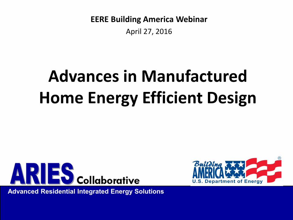
Window Installation

9
Ductless, Mini-split Heat Pump • NO DUCTS, no site work • Transfer fans for distribution • Cost competitive • High efficiency • Factory installed • Interior space saving (no furnace)

10
Other Home Features
• ENERGY STAR appliances • Low-e, argon filled windows • Quiet transfer fan distribution • Dedicated fresh air ventilation • 25% more airtight • Reduced thermal bridging

11
Wall tests with foam
(Fleetwood, Riverside, CA)
Technology Refinement
Prototype with advanced walls
(Karsten Homes, Sacramento, CA)
Advanced roof tests (Golden
West, Perris,
CA)
Advanced roof tests (Fleetwood, Riverside, CA)
Advanced walls and roof prototype (Skyline, Woodland, CA)

12
Research Questions
• Program design. Is ZERH suitable for manufactured homes? What changes to ZERH would better recognize the unique features of factory building?
• Use of MSHPs. Can point-source space conditioning achieve comfort targets?
• Costs. What’s the incremental cost of achieving ZERH? Is it cost-effective?
• MSHP performance. How does MSHP perform in service?

13
Russellville Lab Houses

14
Site
North

15
House Specifications
Items House A House B House C
Floor R-14 Fiberglass blanket
R-28 Fiberglass blanket
R-28 Fiberglass blanket
Wall R-12 R-11 (Fiberglass batts )+ R-1 (¼-in ThermalStar board)
R-14 R-13 (Fiberglass batts)+ R-1
(¼-in ThermalStar board)
R-18 R-13 (Fiberglass batts) + R-5 (1-in.
Extruded polystyrene)
Windows U: 0.47, SHGC: 0.73 Single pane, metal frame
U:0.31, SHGC: 0.33 Double pane, vinyl frame, low-emissivity, argon filled
U: 0.30, SHGC: 0.23 Double pane, vinyl frame low-emissivity, argon filled
Ceiling R-22 Blown fiberglass
R-33 Blown fiberglass
R-45 Blown fiberglass
Dense-packed at eaves
Air Sealing Foaming ceiling penetrations, caulking under bottom plates and between top plates and ceiling, marriage line gasket
Mechanical Ventilation
POS Fresh air duct to air handler
No mechanical damper
POS Fresh air duct to air handler
No mechanical damper
Exhaust Fan 45 cfm
Space-Conditioning Distribution
Ducts Metal in-floor ducts sealed with mastic; R-8 crossover
duct between sections
Ducts Metal in-floor ducts sealed with mastic; R-8 crossover
duct between sections
Transfer Fans

16
House Specifications
House A House B House C
Cooling Equipment
Intertherm Air conditioner
Capacity: 23.4 kBtuh EER: 11.0, SEER: 13.0
Intertherm Air source heat pump
Cooling capacity: 18 kBtuh EER:11.0, EER: 13.0
Heating capacity (47°F): 20.2 kBtuh HSPF: 8.0
Mitsubishi Variable-speed mini-split heat pump with outdoor
unit assisted by temperature-controlled
heaters when temperature falls below 69°F in the
bedrooms Outdoor unit: MUZ-
FH15NA Indoor unit: MSZ-FH15NA Cooling capacity: 15 kBtuh
EER: 12.5 SEER: 22.0
Heating capacity at 47°F: 18 kBtuh; HSPF: 12.0
Heating capacity at 17°F: 11 kBtuh
Heating Equipment
NORDYNE Electric furnace
Capacity: 35 kBtuh
Air Handling Unit
NORDYNE Electric furnace, E3EB-
010H, downflow set to low speed. Resistance heating
capacity: 10 kW Air handling unit wattage
(heating elements + blower) :10.4 kW
NORDYNE Electric furnace, E3EB-010H, downflow
set to low speed. Resistance heat capacity: 10 kW
Air handling unit wattage (heating elements + blower) : 10.4 kW

House C Airflows

18
Commissioning Results
Test Method House A House B House C Enclosure Leakage
Multipoint depressurization test
4.7 ACH50 4.6 ACH50 3.8 ACH50
Duct Leakage Duct blower depressurization test
54 cfm25 to outside
~10 cfm25 to outside
N/A
Ventilation Rate
Powered flow hood 44 intermittent 32 intermittent 45 continuous
Air Handling Unit Air Flow
Pressure equalization 980 cfm 1,000 cfm Variable

19
18 Months of Monitoring

20
Measurements
One-minute data uploaded daily: • Air temperature • Relative humidity • Condensation • Power consumption • Status • Current • Solar radiation
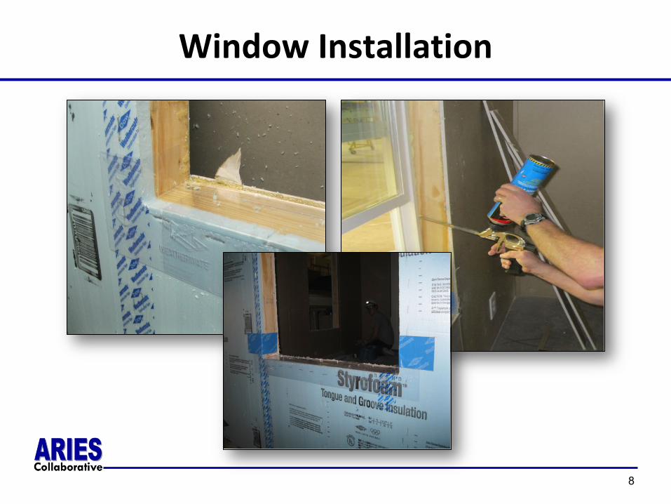
Results - Cooling
21
Configuration: Interior doors open Window blinds at 50% Data Aug 29-Sept 7, 2014, Avg. OAT. 77.3°F
House A (HUD-Code)
House B (Energy Star)
House C (ZERH)
Total Cooling (avg. kWh per day)
15.0 14.5 7.4
Average Indoor Temp (F) 76.4 75.9 75.4
Cooling Set Point (F) 76 76 73-75
Average Relative Humidity (%) 46% 48% 59%
Air Handler Fan Runtime 31% 37% N/A
Ventilation - Effective Continuous Rate (cfm)
14 12 45

22
Cooling Power Relative to Outdoor Temperature
(Aug. 29–Sept. 15, 2014)

House A - Cooling
23
°F indoor
°F Outdoor

House B - Cooling
24
°F indoor
°F Outdoor

House C - Cooling
25

Results - Heating
26
Configuration: Interior doors open. Window blinds at 50% Data Nov 12-17, 2014
Avg. OAT 41.3°F
House A (HUD-Code)
House B (Energy Star)
House C (ZERH)
Total Heating (avg. kWh per day) 48.7 18.1 16.6
Average Indoor Temp (F) 71.3 69.9 69.5
Heating Desired Temperature (F) 71 71 71
Average Relative Humidity (%) 28% 30% 33%
Air Handler Fan Runtime 22% 33% N/A
Ventilation - Effective Continuous Rate (cfm)
10 11 45

House A - Heating
°F indoor
°F Outdoor
27

House B - Heating
°F indoor
°F Outdoor
28

House C - Heating
°F indoor
°F Outdoor
29

House C with Resistance Heat in Bedrooms
(Jan. 6–13, 2015)
30

31
Heating Energy Compared to Outdoor Temperature
(Jan. 6–13, 2015)
32
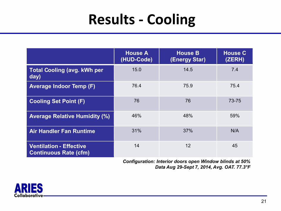
House B Backup Electric Resistance Heating Energy

33
House C Heat Pump, Transfer Fan, and Resistance Heating Energy
(Jan. 6–13, 2015)

34
Energy Consumption
• House B used slightly less energy than House A for cooling.
• House C used half the cooling energy of Houses A and B.
• House B and House C consumed about the same amount of heating energy.
• Compared with B and C, House A used about three times the heating energy.

35
Effective Ventilation Rates
The required whole-house ventilation rate should be 0.035 ft3 per square foot of the conditioned space or a minimum of 50 cfm.
Conditioned area = 1,210 ft2.
Whole-House Ventilation Flow (cfm)
House Measured Code Required
A 22
50 B 13
C 45

36
Wall Cavity Conditions
(April 2014–April 2015)
House Condition Temp. (°F) Humidity (%) Wood Moisture Content (%)
Dew Point (°F)
B Maximum 91.6 71.0 14.2 67.2
Minimum 27.0 38.2 7.0 7.9
Avg. 64.8 54.7 9.5 48.0
C Maximum 86.2 77.4 14.6 73.3
Minimum 32.5 40.0 7.0 15.9
Avg. 65.2 62.2 11.6 52.1

37
Monthly Peak Electric Demand
House Avg. Monthly Peak Demand During Peak Hours
Avg. Demand Reduction Compared to House A
A 3.1 N/A B 2.6 18% C 1.0 69%

Attic Temperatures
38

39
Heating System COPs
• The COP of the heating system was calculated for all three houses using a co-heat method.
• For House B and House C, the COP of the heat pumps was also measured using airflow measurements.

40
Measured Heating COPs
House / Equipment Type A
NORDYNE Electric Furnace
B Intertherm Heat
Pump C
Mitsubishi
UA (Incl. Infiltration) Btu/h/°F
313 245 209
COP (Co-heat method) 1.10 2.50 2.49 COP (Co-heat method) (without ventilation adjustment)
1.00 2.26 1.63
COP (air-side method) Not measured 1.37 1.39 Expected COP, Based on manufacturer data
1 (Lower due to duct
leakage) 3.2
(Lower due to duct leakage)
4.8

41
COP Measurements
Air-side method may be less reliable than the co-heat method due to: • Non-uniformity of supply air
measurements. • Room-to-room temperature differences • Higher convective airflow due to air
handling unit operation than existed during the co-heat tests
• Variations from estimated ventilation rates
COPs calculated by the co-heat method are taken to be closer to actual performance.
House B refrigerant coil in heating mode showing non-uniform temperatures

42
Auto Setting Resulted in Low Fan Speed
Air handling unit fan power for auto- and high-speed settings
Fan curve based on onetime flow and power measurements
43
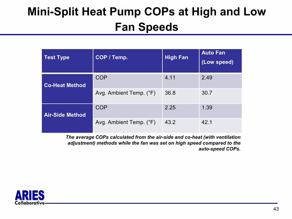
Mini-Split Heat Pump COPs at High and Low Fan Speeds
The average COPs calculated from the air-side and co-heat (with ventilation adjustment) methods while the fan was set on high speed compared to the
auto-speed COPs.
Test Type COP / Temp. High Fan Auto Fan (Low speed)
Co-Heat Method COP 4.11 2.49
Avg. Ambient Temp. (°F) 36.8 30.7
Air-Side Method COP 2.25 1.39
Avg. Ambient Temp. (°F) 43.2 42.1

44
COP as Function of Ambient Temperature
Comparison of mini-split COP with low (auto) and high fan speeds
Co-heat measurement method Air-side measurement method

45
Stratification Impact on COP
• High return temperatures may reduce COP • January 6‒13 average living room temperature:
Height Temperature (°F) Entering heat pump 74.8 84 in. above the floor 75.4 60 in. above floor 70.2 12 in. above the floor 68.9

46
Extrapolating Energy Use
• Objective: Based on measured data, estimate space conditioning energy use in a range of Southeast climates.
• Method: Simulation with field-data-calibrated energy models using BEopt with Energy Plus engine.

47
3 Locations, 5 Models
Model Thermal Envelope Space Conditioning Data Source
A1 HUD code Electric resistance furnace; Split system ACa Measured
A2 HUD code Heat pump furnace; Split system AC Simulated B1 ENERGY STAR Electric resistance furnace; split system AC Simulated B2 ENERGY STAR Heat pump furnace; split system AC Measured
C ZERH (IECC 2012) Ductless mini-split heat pump Measured

48
Modeling Results – Knoxville Whole House Site Energy

49
Modeling Results – Knoxville Space Conditioning Site Energy

50
Energy Savings and Payback: Knoxville, TN
Compared to House A
House C compared to House B
House Annual Utility Cost
Savings Incr. Retail Cost
Payback (yr)
A $1,656 N/A N/A N/A B $1,263 $393 $2,268 5.8 C $1,055 $601 $5,843 9.7
Savings Incr. Retail Cost
Payback (yr)
$208 $3,575 17.2

51
Research Questions
• Program design. Is ZERH suitable for manufactured homes? What changes to ZERH would better recognize the unique features of factory building?
• Use of MSHPs. Can point-source space conditioning achieve comfort targets?
• Costs. What’s the incremental cost of ZERH? Is it cost-effective?
• MSHP performance. How does the MSHP perform in service?

52
Responses to Research Questions
1. Program design. Is ZERH suitable for manufactured homes? What changes to ZERH would better recognize the unique features of factory building? • House C was built in compliance with the HUD code and
DOE ZERH criteria. • The use of a ductless heat pump simplified the compliance
with ENERGY STAR version 3 HVAC requirements. • Thermal envelope, ventilation, and indoor air quality
requirements were not a barrier, although they did add costs.
• Existing ZERH criteria did not present a barrier for manufactured homes using this space conditioning strategy.
53
Responses to Research Questions
2. Use of MSHPs. Can point-source space conditioning achieve comfort targets? • The ZERH performed reasonably well in cooling. There was
some temperature fluctuation from one room to another but only the master bathroom exceeded the upper bounds of the ACCA temperature range (with the interior doors closed).
• In heating, the bedrooms did not maintain acceptable temperature. Resistance heaters were needed mainly when the ambient temperature was below freezing.

54
More Comfort Related Findings
• Open doors may obviate the need for transfer fans • Closed doors are more consequential during the
heating season • Window shading (closed blinds) is an important
cooling energy savings and comfort strategy • Convective heat transfer through open doors was
approximately 140 to 281 cfm • Transfer fans are of limited value when doors are open • Transfer fan low-high configuration not beneficial

55
Responses to Research Questions
3. Costs. What’s the incremental cost of achieving ZERH? Is it cost-effective?
• House C had 50% space conditioning savings compared to House A
• Strategies are available for reducing backup heat and increasing mini-split COPs
• Equipment improvements have a larger, relative impact on energy use than envelope improvements
Based on estimated costs at high production volumes
House C Compared to A / B
Energy Measure Manufacturer Cost
Premium
Homeowner Payback Based on Retail Costs
House A $2,060 8.8 years
House B $1,166 17.5 years

56
Research Questions and Responses
4. MSHP performance. How did the MSHP perform in service? • The COP of both the conventional split-system
heat pump and the ductless mini-split were approximately 2.5.
• For the mini-split, this is well below the expectation based on manufacturer data.
• When the mini-split was run on its high-speed, its COP increased to 4.11. That is, low airflow lowers operating efficiency.

57
Other Findings of Note: Moisture
• Wood moisture content. Slightly elevated in House C but within safe limits. Likely due to exterior foam insulation reducing vapor permeability. Condensation risk mitigated by 5.5°F higher dew point at condensation surface.
• Relative humidity. RH within acceptable limits (latent loads not simulated). Short-term humidification testing revealed little impact on RH, indicating that equipment had sufficient capacity to handle the latent loads during hot weather.
58
Other Findings of Note: Peak Loads
• House B averaged 18% lower peak than House A • House C averaged 69% lower peak than House A • Some House B winter peaks similar to House A
indicating that House B’s peak occurred electric resistance is the primary heating source

59
Full Report
Field Evaluation of Advances in Energy-Efficiency Practices for Manufactured Homes, E. Levy, J. Dentz, E. Ansanelli, G. Barker, P. Rath, and D. Dadia (ARIES Collaborative) http://apps1.eere.energy.gov/buildings/publications/pdfs/building_america/65436.pdf

60
Awards and National Recognition
61
Design Changes
• Ventilation system • Distribution system • Thermal enclosure

62
Ventilation System Analysis
• BEopt analysis of 6 options in 4 northern climates
1450
1500
1550
1600
1650
135 140 145 150 155 160
Ener
gy r
elat
ed c
osts
, Ann
ualiz
ed ($
/yr)
Source energy consumption (MMBTU/yr)
Energy Related Costs, Annualized ($/yr)- Harrisburg, PA
AirKing ES80-Exhaust
Non recovery type: Balance
Broan XB50-Exhaust
WhisperComfort 100CFM
WhisperComfort 40CFM
Broan HRV 70SE

63
Ventilation System Conclusions
• Panasonic WhisperComfort ERV 40CFM has lowest source energy consumption, but flow rate too low
• Source energy for all options similar – savings potential small
• Manufactured homes typically have exhaust fans which can be repurposed for whole house ventilation and thus are suitable from an ease of construction standpoint
• Low first cost makes exhaust fans attractive to manufacturers

64
Distribution System Redesign
Goals: • More airflow • Quieter Strategy • Straight through wall • Different fan

65
New Distribution System Testing

66
Monitoring Results with New Fans
55.0
60.0
65.0
70.0
75.0
80.0
0.0 20.0 40.0 60.0 80.0
Indo
or te
mp
in d
eg F
Outdoor temp in deg F
NE BR: BR3
Doors open, fans on: BR3 Doors open, fans off: BR3
Doors closed, fans off: BR3 Doors closed, fans on: BR3
55.0
60.0
65.0
70.0
75.0
80.0
0.0 20.0 40.0 60.0 80.0
Indo
or te
mp
in d
eg F
Outdoor temp in deg F
MBR
Doors open, fans on: MBR Doors open, fans off: MBR
Doors closed, fans off: MBR Doors closed, fans on: MBR
Setpoint
About as effective as an open door

67
Thermal Enclosure Revisions
• R-4 windows • 2x6 walls • More floor insulation • Tighter envelope

68
New Cold Climate ID House
69
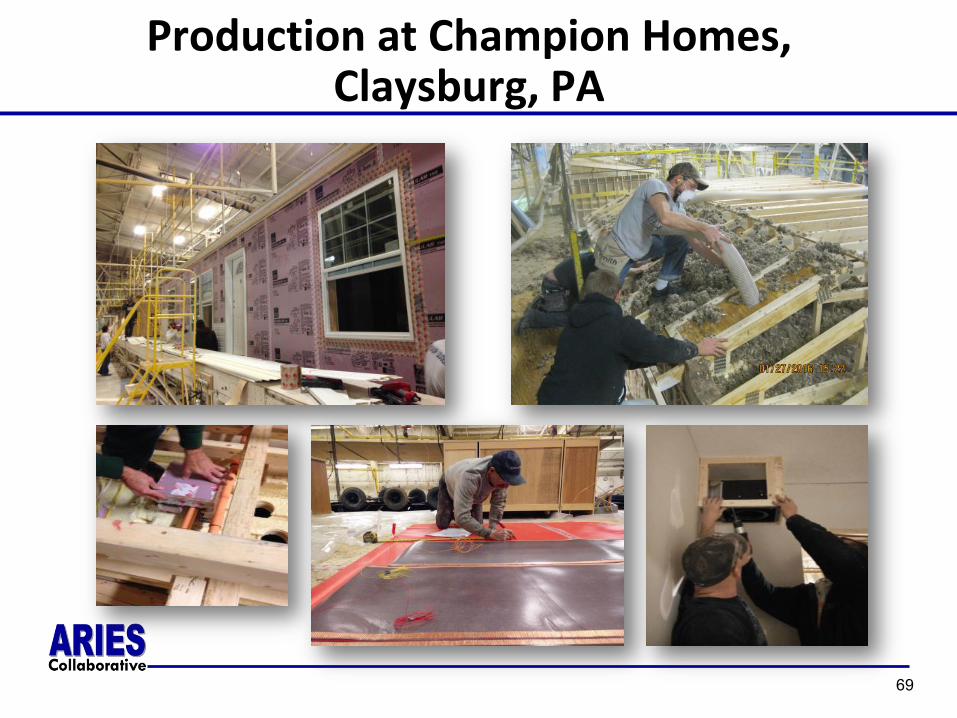
Production at Champion Homes, Claysburg, PA

70
Installation in Eatontown, NJ
• Six months unoccupied monitoring and testing
• One year occupied monitoring

71
Ribbon Cutting

72
Initial Testing Data

73
Next Steps
• Building America Implement internal gains Continue monitoring Occupancy Design two homes with Habitat using same
principles • NYSERDA Design and build two manufactured ZERH for
New York State