advances in igcc projects & technology for the next ... · • 33 ge licensed gasification...
TRANSCRIPT

Advances in IGCC projects & Technology for the next generation of IGCC & Carbon Capture CC(+S) plants
Marcus Scholz2010
GE Energy
���������� ������
Agenda
• IGCC Project experience & current activity• Lessons learnt & technology
improvements• GE’s Carbon Island™ technology• Carbon Capture levels• Gas Turbine hydrogen fuel flexibility

���������� ������
Leadership • Gasification leadership since 1948 with
>70 facilities operating worldwide • >130 gasification vessels in operation
Experience• First coal gasification plant in 1978• First pet coke gasification plant in 1984• 27 gas turbines operating on syngas …> 1 million
operating hours• IGCC leader… > 3 GW with GE technologies
- Cool Water technology demo plant 1984-1989- TECO commercial demonstration plant 1996-
present- DUKE Energy commercial plant …COD 2012
GE’s leadership & experience

���������� ������
Diverse Solutions – based on Gasification
Substitute Natural Gas• SNG
…> 60 years !
Chemicals• Ammonia• Methanol• Oxo-chemicals
Power Generation• Electricity• Steam• Hydrogen + CO2
Refinery Polygeneration• Hydrogen• Steam• Power
Transportation Fuels• Jet• Diesel
Feedstocks:• Coal • Pet coke• Asphalt• Heavy Oil• Vacuum Residue
���������� ������
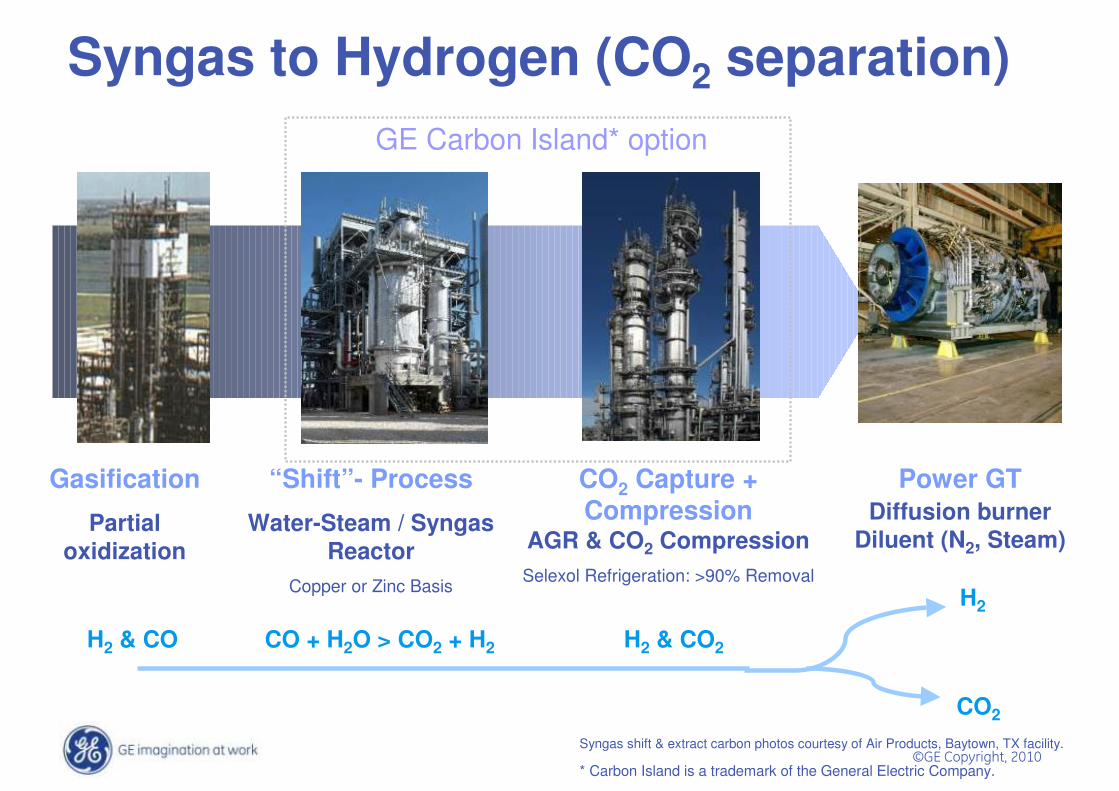
Syngas to Hydrogen (CO2 separation)
Gasification
Partial oxidization
“Shift”- Process
Water-Steam / Syngas Reactor
Copper or Zinc Basis
CO2 Capture + Compression
AGR & CO2 CompressionSelexol Refrigeration: >90% Removal
Power GTDiffusion burner
Diluent (N2, Steam)
Syngas shift & extract carbon photos courtesy of Air Products, Baytown, TX facility.
CO + H2O > CO2 + H2H2 & CO H2 & CO2
H2
CO2
GE Carbon Island* option
* Carbon Island is a trademark of the General Electric Company.

���������� ������
IGCC Plants evolution
Pilot(1984-89)
Coolwater• 120 MW IGCC
• 7E Gas Turbine
• development project
Tampa Electric • 250 MW IGCC
• 7FA Gas Turbine
• 5 Year Construction
Duke Energy• 630 MW IGCC
• 7FB Gas Turbine
• 3 Year Construction
Commercial(1996 – today)
LargeCommercial(2012 - tomorrow)

���������� ������
Licensee/Owner: Sarlux S.r.lOperator: SARAS S.p.A.Location: Sardinia, ItalyStartup: 2001Feedstock: Visbreaker tarDesign Capacity: 1,200 mTPDOperating Pressure: 38 barGasifier Size: 3 x 900 ft³Power Block: 3 x GE 9E GT’s,
3 x GE Steam turbinesEPC Contractor : Snamprogetti S.p.A.
Gasification & Carbon Extraction
Gas Cooling &
COS Hydrolysis
Oxygen
VisbreakerTeer
ElementalSulfur
Sulfur Claus &
Recovery
Steam export refinery
Power to Grid
IGCC – Polygeneration SARLUX 550MW
GE Combined
Cycle
Hydrogen Production
H2 to Refinery
3,600 t/day
551 MW
40,000 Nm3/h
MP = 100 t/h; LP =85 t/h
Black WaterTreatment
Filtration cake
Metal recovery
Steam to export
90+% availability (no spare)

���������� ������
Duke Energy Edwardsport IGCC • Nominal 630MW, 207FB CCGT
• COD in 2012
• Construction on-track
• 2x RSC + gasifier shipped in 2009
• 7F Syngas turbines ship in 2010
• Wide coal & pet coke fuel envelopeDuke Energy Edwardsport site construction, Sept. 2009
���������� ������
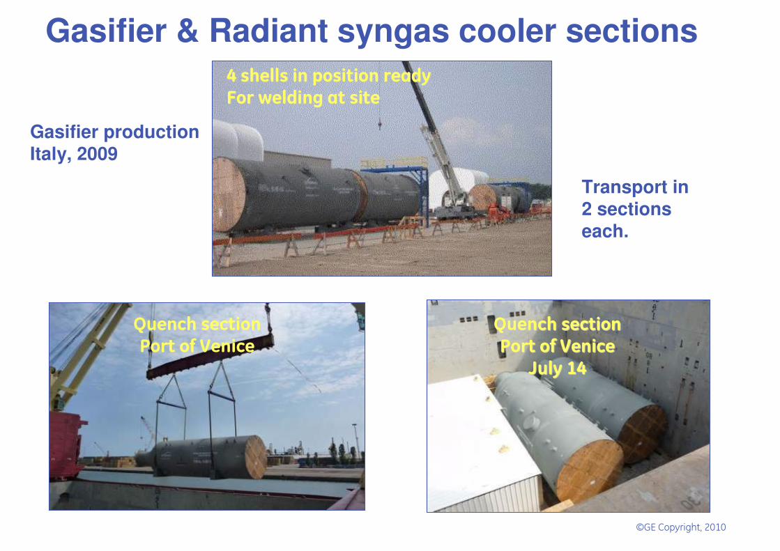
Gasifier & Radiant syngas cooler sections�������������������� ����������������������� ���
����������� ����������������� ������
����������������������������
������������������������
��������������
��������������������������
Gasifier productionItaly, 2009
Transport in 2 sectionseach.

���������� ������
Gasification Area
Coal unloading Area
RSC assembly area
Duke Edwardsport IGCC … July 2009
Gasification IslandConstruction
COALHarbour
GasifierSection assembly

���������� ������
Take aways: IGCC is about integration
����
� ��� � �����
���
��� ���
���� �����
��������
Value proposition:– 48 month cycle (FEED to COD)
Eliminate 1 yr. from custom IGCC sched.– Wide bituminous fuel envelope (ash+S) – Carbon capture ready– Fully integrated Mark VIe control
system with 12 mo. factory accept. test– Virtual plant simulator…Failure modes
mitigated, Operators trained before startup

���������� ������
Today:• Detailed design complete• Components at site• On-site assembly in process
Radiant syngas cooler
2006:• Lessons learned• Detailed analysis• Improved design meth.• Availability &
performance improvmt.• 30% better perform.;
30% lower cost; higher reliability versus TECO configuration
1996:First application:TECO

���������� ������
Today:• Stage testing in process• Simulators in operation• Operators in training• Design validation
Next Steps:• Site transition• ICS delivery
Integrated controls and simulation
��
��������� �����
�������� ��� ���� ��������������������� ��� ������
����� �� ��� ���� �������������������� �������
������������� �������� ������
� ������� � ��� ����! ���" ������� #��$��
������� �� � ����� ���� �� �!�"����� ��
#�� � ����� �� �!�����$ �% ����� �
& ��'�(��� ��� ���� ��� � �)*%
#�� � ����� �� ���� ����$ �% ����� �
�#��
��%
�#��
��&
�#��
��'
�������� ��� ���� ��������������������� ��� ������
��� ���� ������������������
�(�� ����� � �������������� �
�(�� �������������������������� ��� ����
(��� ��� ��+��� �)*%
������� ������,��� ��� ��� ������� � ������
�� ���������$ � �������- �� ��� ��� �
#�� � ���� ������� ����� ���� �� ������������ ��� ���� �� � ��
)������*��� �� �
2006:NPI Project
2008:Detailed Validation Plan• Physics based - emulated• Stage testing• Field validation• Operator training simulator
���������� ������
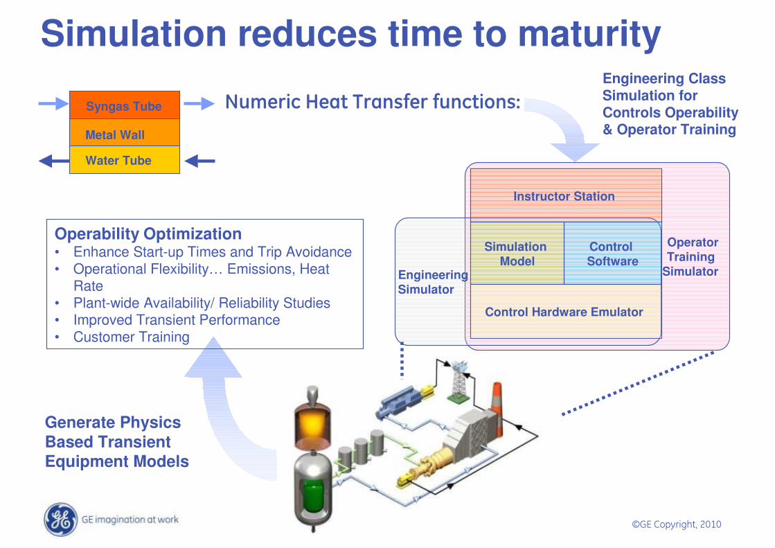
Metal Wall
Syngas Tube
Water Tube
OperatorTraining
SimulatorEngineering Simulator
Control Hardware Emulator
Simulation Model
Control Software
Instructor Station
Generate Physics Based Transient Equipment Models
Engineering Class Simulation for Controls Operability & Operator Training
Simulation reduces time to maturity
Operability Optimization• Enhance Start-up Times and Trip Avoidance• Operational Flexibility… Emissions, Heat
Rate• Plant-wide Availability/ Reliability Studies • Improved Transient Performance• Customer Training
� �� ���+�! �� ������,���,��+ ����-

���������� ������
Improving initial availability
Reference plant Goal: initial availability of 85%
47.8
64.8
88.7 92.7 90.688.7
1996 1997 1998 1999 2000 2001
TECO Polk Unit 1 IGCC AvailabilityGasifier on Stream Factor
Combined Cycle Availability Factor
���������� ������
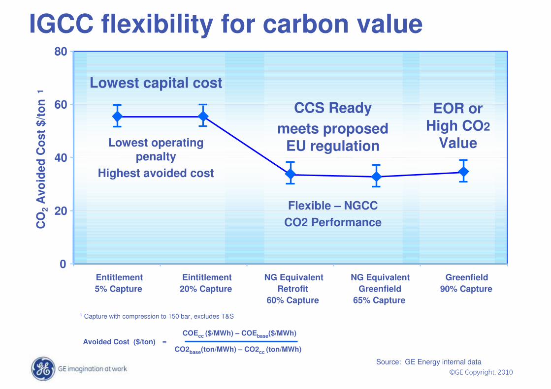
IGCC flexibility for carbon value
0
20
40
60
80
Entitlement5% Capture
Eintitlement20% Capture
NG EquivalentRetrofit
60% Capture
NG EquivalentGreenfield
65% Capture
Greenfield90% Capture
CO
2A
void
ed C
ost $
/ton
1
Lowest capital cost
Lowest operating penalty
Highest avoided cost
CCS Readymeets proposed
EU regulation
Flexible – NGCC CO2 Performance
1 Capture with compression to 150 bar, excludes T&S
EOR or High CO2
Value
Source: GE Energy internal data
COEcc ($/MWh) – COEbase($/MWh)
CO2base(ton/MWh) – CO2cc (ton/MWh)Avoided Cost ($/ton) =

���������� ������
GE’s Carbon IslandTM
• Greenfield • Retrofit
– Minimal cost/availability impact– Integrated with existing Acid Gas
Removal (AGR)– Installed during turbine
maintenance • Multiple carbon capture capability
options• Commercial technologies
– 33 GE-licensed units operating worldwide using shift reaction
. High purity CO2
. Small footprint – 2 acres
. Reliable CO2 separation process
. Install as greenfield or as an economical retrofit for 65% CO2 capture

���������� ������
IGCC CO2 Capture Readiness
CO2SHg
Water Gas Shift(50%-65% capture)
PowerPower
Oxygen,Feedstock
Process Gas OnlyHigh P, Low Vol
High Driving Force
Slag
Proven Process
AGR / SRUAGR / SRUOptional ShiftOptional ShiftGasificationGasification
Diffusion CombustorDiluent NOx
Control
H2
Proven Turbines
Proven Gasification
• 27 GE Gas Turbines operating at 50%-95% H2
• 70 GE Licensed Gasification Plants operating worldwide
• 33 GE Licensed Gasification Plants operating worldwide removing CO2 and producing H2

���������� ������
Experience
Scale-up Pilot(10-30MWt)
Small Commercial(50-100MWt)
LargeCommercial
(>350MWt)
Com
mer
cial
Sta
tus
Med
2Lo
w3
Full1
1Commercially offered… guaranteed cost & performance2 Requires shared risk & cost for scale-up to pre-or-full commercial3 Technical feasibility only… unknown cost, performance &
integration barriers
Pre-combustion (IGCC)Commercial plants
(up to 450MWt >90% CC)
Post-Combustion (Amine)
Slipstream NG & coal(Max ~60MWt NGCC)
Post-Combustion (Powerspan)
Slipstream pilot (1MW)
Post-Combustion (Chilled Ammonia)Slipstream Pilot (5MW)
Oxy-combustion30MW pilot
Chemical LoopingMe/MeO ox/red
Bench scale
Carbon capture technology maturity
Feasibility(1-5MWt)
Bench

���������� ������
Combustion SystemCombustion System
Cold End
Drive
Axial Exhaust
Small Modifications to existing Gas Turbine Platform
Hot Gas PathHot Gas Path
Hydrogen Combustion in Gas Turbines
Hydrogen has been used in Gas Turbines for over 30 years,
primarily in Refinery applications..

���������� ������
B/E-class High Hydrogen ExperienceProject / Site
GT Model
No. Units
Fuel Gas Features
Geismer, US MS6001B 1 PG up to 80% H2 Refinery, US MS6001B 1 RFG 12 - 50% H2 Korea MS6001B 1 PG up to 95% H2 Tenerife, Spain MS6001B 1 RFG ~70% H2 Cartagena, Spain MS6001B 1 RFG 66% H2 San Roque, Spain MS6001B 2 RFG 70% H2 Antwerpen, Belgium MS6001B 1 RFG 78% H2 Puertollano, Spain MS6001B 2 RFG up to 60% H2 La Coruna, Spain MS6001B 1 RFG up to 52% H2 Rotterdam, NL MS6001B 1 RFG 59% H2 Schwarze Pumpe, GER MS6001B 1 IGCC 62% H2
Vresova, CZ MS9001E 2 IGCC 46.8% H2 Fawley, UK MS9001E 1 RFG ~50% H2 Georgia Gulf, US MS7001EA 3 Blend Methane + 50% H2 Milazzo, ITA MS5001P 1 RFG 30 - 50% H2 Ref., India MS5001P 1 RFG 50% H2 Paulsboro, US MS5001P 2 RFG 20 - 60% H2 Ref., Int'l MS5001P 1 RFG Propane + 60% H2 Reutgerswerke, US MS3002J 1 PG 60% H2 NUP MS3002J 1 TG ~60% H2 Donges, US GE10 1 RFG 76% H2 Refinery, Jordan PGT10 1 RFG 82% H2 RFG = Refinery Gas, TG = Tail Gas, PG = Process Gas, IGCC = Syngas
Fleet Leaderavg. 90% H2more than 10 yrs

���������� ������
F-class Hydrogen ExperiencePSI
WabashTampa
PolkExxon
SingaporeValaro
DelawareTurbine 7FA 7FA 2x6FA 2x6FAH2 (% vol) 24.8 37.2 44.5 32.0
CO 39.5 46.6 35.4 49.5CH 4 1.5 0.1 0.5 0.1CO2 9.3 13.3 17.9 15.8N2+Ar 2.3 2.5 1.4 2.2H2O 22.7 0.3 0.1 0.4
LHV BTU/ft 3 209 253 241 248kJ/m3 8,224 9,962 9,477 9,768
Tfuel F/C 570/ 300 700/ 371 350/ 177 570/ 299H2/CO Ratio 0.63 0.80 1.26 0.65Diluent Steam N2 Steam H2O/ N2
Equiv BTU/ft 3 150 118 116 150kJ/m3 5,910 4,649 4,600 5,910

���������� ������
Summary• 60 years of experience in gasification
operation and innovation
• 25 years of IGCC experience
• Significant investments in design methods; tools; and validation facilities
• 16 months from first fire of Duke Energy IGCC facility
• Investing in next generation industrial and power gasification technology