advances in control and sensors · pdf fileadvances in control and sensors technology enabling...
TRANSCRIPT
ADVANCES IN CONTROL AND SENSORS TECHNOLOGY
ENABLING UNMANNED OPERATION OF CONTAINERS CRANES Alojz Slutej, Fetah Kolonić ABB Ind. Systems AB, Faculty of Electrical Engineering and Computing S-721 67 Västerås, Sweden, HR-10000 Zagreb, Unska 3, Croatia
[email protected], [email protected]
Abstract. This paper summarizes the most important advances of the used crane control technology in perspective of unmanned operation of container cranes. Unmanned operation with remote control support today is available for almost all types of new/existing rail mounted container cranes. Storage capacity is the limitation for most terminals today; unmanned operation offers optimum stacking density and peak capacity equivalent for continuous manning of every crane. Besides that, most of the benefits could be emphasizing in reduction of labor cost, high and uniform productivity, integration with terminal planning system, etc. Unmanned operation requires sensor systems for target position (TPS), sensors for load position (LPS), video equipment on spreader/crane, control and communication equipment on the crane and remote consoles for video and control signals. To remain fully operational with terminal at all times requires extraordinary work flows, narrow time schedules and lots of work which do considerably drive up the overall investment.
Keywords. Sensors, load position system, target position system, automatic guided vehicle, unmanned crane control, sway control, skew control
1. INTRODUCTION
Requirements of modern containers cranes result in demand for sophisticated crane control automation systems and reliable connection to the customer overriding information systems. These systems continuously provide up-dated information about containers moves and crane status, [1,2]. To achieve an efficient and profitable modern container terminal design overall, following sequence should be applied:
• Select the optimum capacity for the terminal
• Select the most efficient terminal concept
• Select economical civil works design
• Select an economical crane concept and
• Automate Applied automation should consider follows:
• Reliability/quality – breakdowns are costly in automated terminals
• Serviceability, support and diagnostics
• Flexibility – capability to handle present and future environment, vehicles, container types, operation principles etc.
• Simplicity- not more equipment than needed
• Safety – present and executed future safety standards
• Standardization and experience The unmanned crane’s motion control system supports basic and advance application function. In order to achieve a number of different possibilities to solve engineered problems, the crane control concept includes:
• Powerful process controller with advanced multitasking, capable of handling several real time critical control loops simultaneously;
• High speed communication links between different clients;
• Advanced sensors technology for accurate measurement and fast transmission of positions and speeds;
• Centralized interface for diagnostics of the complete system. Crane control system includes a wide range of well-proven solutions (including hardware and software) that are divided into blocks for easy adaptation to each client’s specification. The control functions are standardized and built up around a basic core that is adapted on a project-to-project basis with add-on blocks. Usually, control system with its software specially developed for cranes, coordinates the entire crane functionality and communicates with, remote I/Os, drive system, information stations and crane automation sensors.
2. CONTAINER TERMINAL AUTOMATION
Most of the vendors have the strategy to lead the technology development, serving clients with products and functions for the continuous improvement of crane productivity overall. For example, crane control systems have today developed and standardized technology and functions to handle all aspects of crane automation such as:
• Ground and rail conditions
• Unmanned operation
• Safety aspects
• Anti-collision and optimal path control
• Automatic job order handling
• Automatic stacking
• Stack optimization
The crane control system includes a wide range of well-proven hardware and software solutions divided into blocks for easy adaptation to each client’s specification, [1]. Most of the vendors of the control system have a long experience in designing the crane control systems. For example, Advant ®Control System supplied by ABB includes:
• Standard and type testing of software
• Effective use of remote I/Os
• Crane environmental design
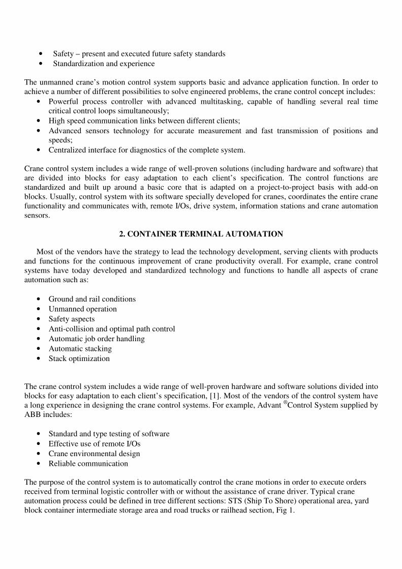
• Reliable communication The purpose of the control system is to automatically control the crane motions in order to execute orders received from terminal logistic controller with or without the assistance of crane driver. Typical crane automation process could be defined in tree different sections: STS (Ship To Shore) operational area, yard block container intermediate storage area and road trucks or railhead section, Fig 1.
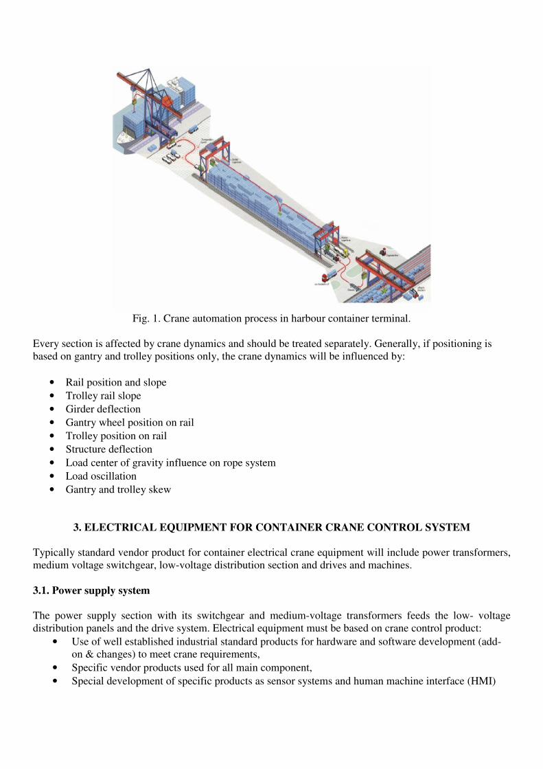
Fig. 1. Crane automation process in harbour container terminal.
Every section is affected by crane dynamics and should be treated separately. Generally, if positioning is based on gantry and trolley positions only, the crane dynamics will be influenced by:
• Rail position and slope
• Trolley rail slope
• Girder deflection
• Gantry wheel position on rail
• Trolley position on rail
• Structure deflection
• Load center of gravity influence on rope system
• Load oscillation
• Gantry and trolley skew
3. ELECTRICAL EQUIPMENT FOR CONTAINER CRANE CONTROL SYSTEM
Typically standard vendor product for container electrical crane equipment will include power transformers, medium voltage switchgear, low-voltage distribution section and drives and machines. 3.1. Power supply system
The power supply section with its switchgear and medium-voltage transformers feeds the low- voltage distribution panels and the drive system. Electrical equipment must be based on crane control product:
• Use of well established industrial standard products for hardware and software development (add-on & changes) to meet crane requirements,
• Specific vendor products used for all main component,
• Special development of specific products as sensor systems and human machine interface (HMI)
Power transformers are of dry resin type with neutral directly grounded and suitable for heavy crane duty and semi-conductor load. To avoid interference it is recommended to use separate transformers: one for the high power main drives and one for the auxiliary devices. Depending on drive configuration and desired electrical characteristics in terms of harmonic suppression the main transformer can have one or two secondary windings.
The medium voltage switchgear has at least one incoming section and two feeder sections. The feeder section for the main transformer has usually a vacuum circuit breaker while the feeder section for the auxiliary transformer is fitted with fused switch-disconnector. Each feeder is fitted with capacitive voltage indication and short-circuits protections.
All used components and building low voltage distribution systems should comply with IEC or UL standards. System is based on a standard core adapted on a project-to project basis. 3.2. Converters and electrical machines
The drive system is formed by converters and electrical machines supported by vendors multi drive package. The converter consists of a regenerative section and is designed to keep the power factor close to unity at all times. The crane drive software is standardized and used in both AC and DC drive systems with standard software core, which consists of speed and torque control with crane-specific solutions. Each crane drive has an inverter connected to the common DC bus bar. The frequency inverters are designed for four-quadrant duty, and braking energy is regenerated into the supply network via the line supply section. Used range from 1.1 to 5500 kW for single drive system for stand alone drives or multi drive for coordinated drives, Fig.2.
Fig. 2. Converters for crane drives.
The winding design of the electrical motors combines a high insulation class and vacuum pressure impregnation, well known for its reliability. AC motors are of cast iron type, IP 55, totally enclosed, with a shaft-mounted external fan and cooling ribs, IC 411 or IC416 for hoist applications. DC motors normally have an IP 23 / IP55 enclosure with forced ventilation provided by built-on constant-speed radial fan blowers. Standard motor accessories are: includes
• Built-on pulse transmitter (optical encoder)
• Winding temperature detectors
• Space heater
4. CONTROL FUNCTIONS IN CRANE OPERATIONS
4.1. Automatic travel sequence
The purpose of the ACCS (Automatic Crane Control System) is to automatically control the crane motions in order to execute orders received from a TLS (Terminal Logistic System) with or without the assistance of a crane driver. The orders are checked by ACCS, then either accepted and executed or rejected. Automatic travel sequence includes:
• Reception of work order from TLS
• Track calculation based upon position and target
• Coordination with the other crane(s) in the block
• Constant recalculation of the track based upon information from TLS/LPS
• Fine alignment upon approach
• Twist-lock operation (mechanical rotary lock between spreader and container)
4.2. Absolute crane positioning system
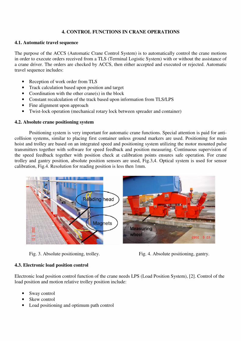
Positioning system is very important for automatic crane functions. Special attention is paid for anti-collision systems, similar to placing first container unless ground markers are used. Positioning for main hoist and trolley are based on an integrated speed and positioning system utilizing the motor mounted pulse transmitters together with software for speed feedback and position measuring. Continuous supervision of the speed feedback together with position check at calibration points ensures safe operation. For crane trolley and gantry position, absolute position sensors are used, Fig.3,4. Optical system is used for sensor calibration, Fig.4. Resolution for reading position is less then 1mm.
Fig. 3. Absolute positioning, trolley. Fig. 4. Absolute positioning, gantry. 4.3. Electronic load position control
Electronic load position control function of the crane needs LPS (Load Position System), [2]. Control of the load position and motion relative trolley position include:
• Sway control
• Skew control
• Load positioning and optimum path control

4.3.1 Sway control
There are a variety of industrial applications where it is necessary for overhead cranes to position containers (loads) in areas that have very little clearance between already stored loads. In these applications, the sudden starts or stops of the trolley or bridge will often cause the load to sway (swing) in an uncontrolled manner. Even with highly skilled crane operators it is not always possible to adequately limit load sway. Load sway can damage the load on the hook or loads already positioned on the final position. It can also damage surrounding equipment and reduce the duty cycle of the material handling operation. More importantly, swaying loads are often a safety hazard for plant personnel.
The amount of acceptable load swing is dependent upon the application requirements and operator preference (semi-automatic mode). There are a lot methods based on optimization of the acceleration and deceleration rates of the trolley and gantry motions. Besides relatively expensive traditional mechanical methods, today's best solutions are based on electronic sway control. There are varieties of control algorithms. Because of nonlinear time variant process with, in many cases, unknown parameters, some authors used adaptive [3], neural network based self-tuning algorithms [4] and predictive PID controller [5]. New control methods employed have been including intelligent algorithms based on fuzzy control (FC) and artificial neural network (ANN) techniques as well as genetic algorithms (GA), [6-14].
Electronic sway control transforms a load speed reference signal given by a driver or an automatic crane control software into a speed reference for the trolley or gantry drive of a crane. The regulator uses the feedback of load position from the LPS sensor system. The signal is filtered in such a way that the drive reference will as quickly as possible bring the load from the present state (speed, sway angle and sway speed) to the speed ordered and no sway. The technique used is very similar to what is used by an experienced crane driver. The trolley (gantry) is accelerated to bring the load in motion and is than slowing down for a moment before accelerating to final speed to be able to get the exact timing to “catch “ the load when it has reached the right speed. The sway control has to be a continuous control able to respond to any reference variations and to any disturbances like wind and initial sway. The control is adjustable to give comfortable working environment for the crane driver on the trolley.
Some benefits of sway control can be summarized in following:
• Crane duty cycle is improved by permitting faster travelling speeds without the need to allow for settling time of a swaying load.
• Product and/or equipment damage is avoided in areas with reduced clearances.
• The potential for injury to operating personnel is greatly reduced by preventing uncontrolled loads sway.
• In semi-automatic mode, operator fatigue is also reduced by eliminating the stress related to numerous jogging and inching operations. This is especially the case for high duty cycle processes. In such applications, the operator must be concerned with meeting production but, at the same time, try to avoid damaging product or equipment.
• Overall operator effectiveness and productivity is improved by eliminating differences between operator techniques in positioning loads.
4.3.2. Skew control
The skew control uses the LPS for feedback of the actual load skew position, Fig.5. The reference is either no skew or a skew angle ordered by the driver. The actuators can be screws powered by AC drives or hydraulic cylinders. The response has to be quite good as the skew motion has a short sway period.

a) b)
Fig. 5. Skew control; basic principal (a); skew control realisation with corresponding drives (b). Skewing is present in the crane too, not only in the load (container), Fig.5a. For example, rail
mounted gantry overhead cranes frequently skew due to poor rail conditions, uneven wheel wear, wheel slippage or unequal load conditions when the trolley is operating at one end of the crane bridge. Skew is a common problem on long span bridge cranes and gantry cranes with single or multiple drives.
Skewing of the crane can cause excessive wheel wear and stress, especially to the wheel flanges. It can also produce horizontal forces at right angles to the rail which can result in unusual stresses to the crane runway beams and building structure. Polyurethane wheels on trackless gantry cranes tend to wear more rapidly than steel wheels. This often results in different diameter driving wheels which subsequently cause the crane to skew. Crane skew also makes it more difficult to spot loads accurately.
Here are some methods for control crane skew:
• If the crane is equipped with independent motor drives on each end truck, the motors will 'slip' keeping the crane in line. Using separate adjustable frequency crane controls for motor control, helps reduce the results of crane skew. In these cases, the amount of skew is still dependent upon the mechanical clearance between the wheel flange or guide roller and the rail. Although wheel and rail wear is reduced.
• In a crane systems, where a PLC is used for automatic crane operation (or can be added), a more positive method can be applied. Distance detection sensors are mounted on the end trucks at each end of the crane. These sensors measure the distance to fixed 'targets' mounted with direct reference to the final spotting positions. The distance sensors are connected to the PLC which in turn is used to control the individual adjustable frequency crane controllers, controlling individual motors on each end truck. The PLC automatically adjusts the output signals to each crane control for any distance deviations detected between the two sensors. Dependent upon the accuracy of the distance detectors, skew can be eliminated during travel and at final positioning.
• Crane system controller uses the two position values to detect the trolley position and the trolley skew angle. The trolley skew is input to the skew control and compensated with the spreader skew machinery (hydraulic or jack) to align the spreader properly for landing, Fig.5b.
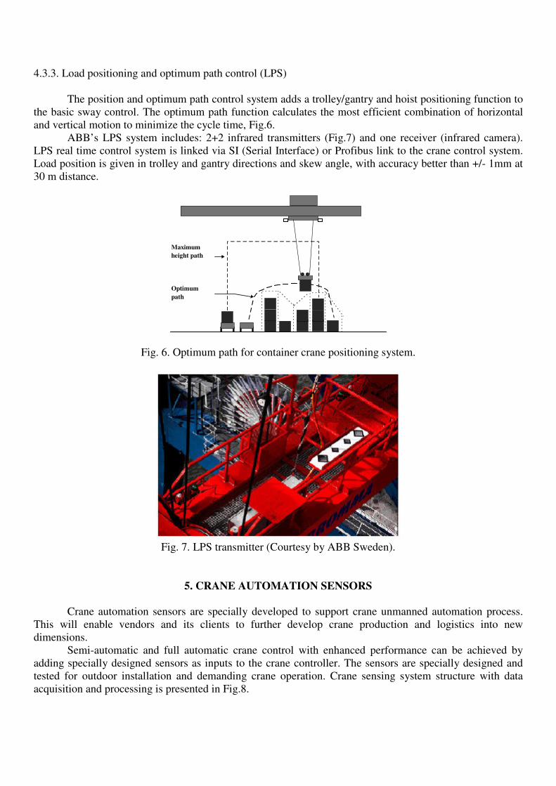
4.3.3. Load positioning and optimum path control (LPS) The position and optimum path control system adds a trolley/gantry and hoist positioning function to the basic sway control. The optimum path function calculates the most efficient combination of horizontal and vertical motion to minimize the cycle time, Fig.6.
ABB’s LPS system includes: 2+2 infrared transmitters (Fig.7) and one receiver (infrared camera). LPS real time control system is linked via SI (Serial Interface) or Profibus link to the crane control system. Load position is given in trolley and gantry directions and skew angle, with accuracy better than +/- 1mm at 30 m distance.
Fig. 6. Optimum path for container crane positioning system.
Fig. 7. LPS transmitter (Courtesy by ABB Sweden).
5. CRANE AUTOMATION SENSORS
Crane automation sensors are specially developed to support crane unmanned automation process. This will enable vendors and its clients to further develop crane production and logistics into new dimensions.
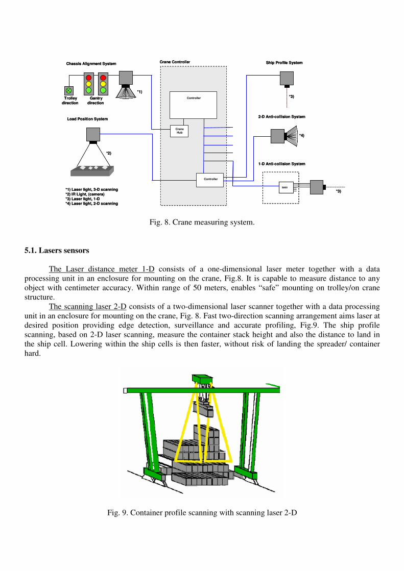
Semi-automatic and full automatic crane control with enhanced performance can be achieved by adding specially designed sensors as inputs to the crane controller. The sensors are specially designed and tested for outdoor installation and demanding crane operation. Crane sensing system structure with data acquisition and processing is presented in Fig.8.
Maximum height path
Optimum path
Crane Controller
Controller
S800
1-D Anti-collision System
Load Position System
Ship Profile System
2-D Anti-collision System
Chassis Alignment System
*1)
*2)
*3)
*3)*1) Laser light, 3-D scanning
*2) IR Light, (camera)*3) Laser light, 1-D*4) Laser light, 2-D scanning
*4)
Crane
Hub
ControllerGantry
direction
Trolley
direction
Fig. 8. Crane measuring system.
5.1. Lasers sensors
The Laser distance meter 1-D consists of a one-dimensional laser meter together with a data processing unit in an enclosure for mounting on the crane, Fig.8. It is capable to measure distance to any object with centimeter accuracy. Within range of 50 meters, enables “safe” mounting on trolley/on crane structure.
The scanning laser 2-D consists of a two-dimensional laser scanner together with a data processing unit in an enclosure for mounting on the crane, Fig. 8. Fast two-direction scanning arrangement aims laser at desired position providing edge detection, surveillance and accurate profiling, Fig.9. The ship profile scanning, based on 2-D laser scanning, measure the container stack height and also the distance to land in the ship cell. Lowering within the ship cells is then faster, without risk of landing the spreader/ container hard.
Fig. 9. Container profile scanning with scanning laser 2-D
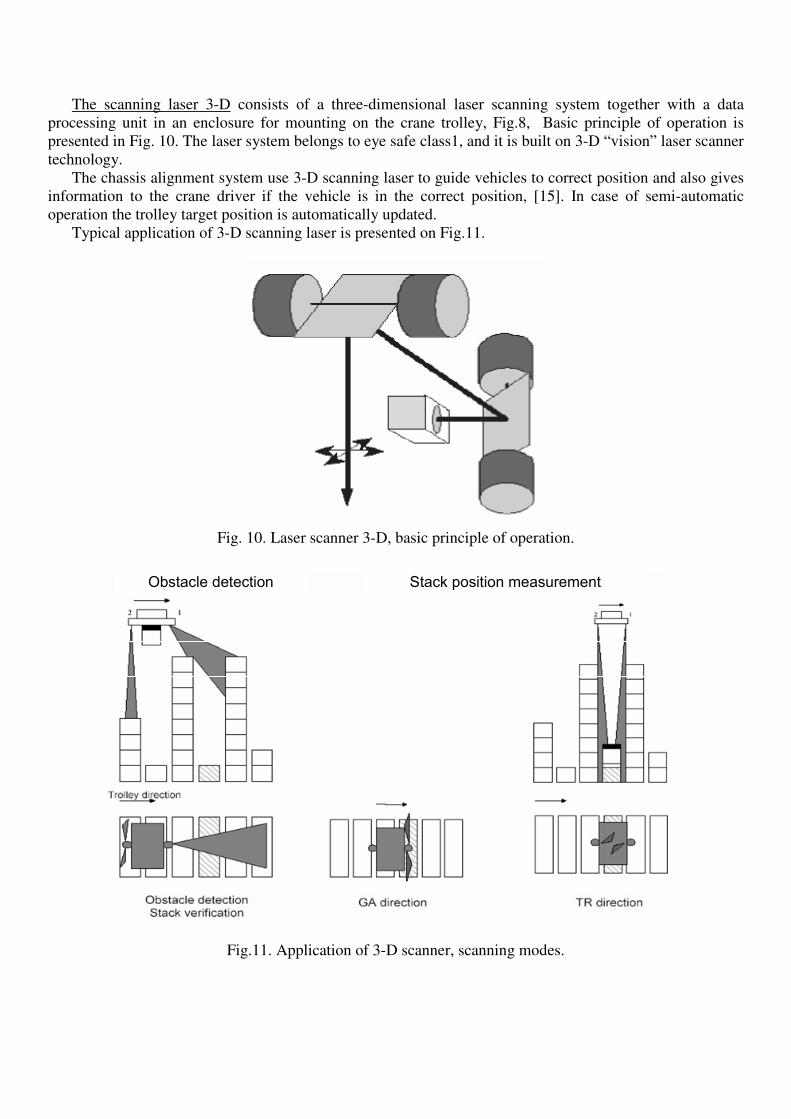
The scanning laser 3-D consists of a three-dimensional laser scanning system together with a data processing unit in an enclosure for mounting on the crane trolley, Fig.8, Basic principle of operation is presented in Fig. 10. The laser system belongs to eye safe class1, and it is built on 3-D “vision” laser scanner technology.
The chassis alignment system use 3-D scanning laser to guide vehicles to correct position and also gives information to the crane driver if the vehicle is in the correct position, [15]. In case of semi-automatic operation the trolley target position is automatically updated.
Typical application of 3-D scanning laser is presented on Fig.11.
Fig. 10. Laser scanner 3-D, basic principle of operation.
Obstacle detection Stack position measurement
Fig.11. Application of 3-D scanner, scanning modes.

Target position sensor (TPS) is based on the 3-D “vision” laser scanner technology. It was initially developed for unmanned OHBC (Over Head Bridge Crane) and RMG (Rail Mounted Gantry) stacking cranes. Main objectives:
• Stack profile scanning
• Anti collision (stack and vehicles)
• Stack profile measurement
• Vehicle position measurement (AGV/truck/chassis) 5. 2. Camera and infrared (IR) light transmitter
The sensor consists of a camera with a digital image processing system in an enclosure for mounting on the crane trolley. The input to the camera comes from an IR light transmitter in an enclosure for mounting on the spreader. These sensors are used for:
• Chassis Alignment System
• Load Position System
• Ship Profile System
• Anti-collision System
6. CONCLUSION
Due to limited storage capacity for the most terminals today, unmanned operation is right solutions which one offers optimum stacking density and peak capacity equivalent for continuous manning of every crane. Almost all types of new or existing rail mounted container cranes could be equipped with sophisticated crane control automation supported with unmanned operation and control facilities. This unmanned operation requires quite sophisticated crane technology and reliable connection to the customer overriding information systems. These systems continuously provide up-dated information about containers moves and crane status. To achieve an efficient and profitable modern container terminal design, crane technology should offer automation sensors, specially developed to support crane unmanned automation process. This enables vendors and its clients to further develop crane production and logistics into new dimensions.
7. REFERENCES
[1] U. Bryfors: "Automatic terminals", ABB Crane Systems, Västerås, 2005. [2] A. Slutej: "The new Multidrive concept for engineered drive application", invited paper, in Proceedings of Conference on Microcomputers in control systems, Mipro’94, vol.2, pp.1-5, Rijeka, Croatia, 1994. [3] G.Corriga, A. Guia, G. Usai: An Implicit Gain Scheduling Controller for Cranes Controller, IEEE
Transaction on Control Systems Technology, Vol. 6. No.1, pp. 15-20, January. 1998. [4] J. Mendez, L. Acosta, L. Moreno, A. Hamilton, G. Marichal: Design of a Neural Network Based Self-
Tuning Controller for an Overhead Crane, Proceedings of the 1998 IEEE Conference on Control on Application, pp. 168-170, Trieste, Italy, 1-4, September 1998.

[5] D. Sohn, J. Min, J. W. Lee, Min, J. M. Lee, Min, K. S. Lee : A Study of ATCS for Automated Transfer
Crane using Neural Network Predictive PID Controller, SICE Annual Conference in Fukui, 4-6. August, pp.3271-3276, 2003.
[6] Z. Nowacki, D. Owczarz, P. Wozniak: On the robustness of fuzzy control of an overhead crane, pp. 433-437, IEEE, 1996. [7] Y. Kijima, R. Ohtsubo, S Yamada, H. Fujikawa: An optimization of Fuzzy controller and its application
on overhead crane, IEEE, pp.1508-1513, 1995. [8] O. Itoh, H. Migita, J. Itoh, Y. Irie: Application of fuzzy logic control to automatic crane operation, Proceedings of IECON'93, Vol.1, pp.161-164, 1993. [9] Y. Suzuki, S. Yamada, H. Fujikawa: Anti-Swing Control of the container Crane by Fuzzy Control, IEEE, pp.230-235, 1993 [10] J. Yi, N. Yubazaki, K. Hirota: Anti-Swing Fuzzy Control of Overhead traveling Crane, IEEE, pp.1298-1303, 2002. [11] M. Nalley, M. Trabia: Control of Overhead Crane using a Fuzzy Logic Controller, Journal of Intelligent and Fuzzy systems, Vol.8;1, pp.1-18, 2000. [12] M. Gutierrez, R. Soto: Fuzzy control of a scale prototype overhead crane, Proceedings of the 37th IEEE Conference on Decision and Control, Tampa, Florida USA, pp.4266-4268, December 1998. (Fuzzy anti-swing controller) [13] Y. Kim, H. Seo, S. Sul: A New Anti-Sway Control Scheme for Trolley Crane System, IEEE, pp.548- 552, 2001. [14] Y. Hakamada, M. Nomura: Anti-sway and position control of crane system, Proceedings of the AMC'96 MIE, pp.657-662, 1996. [15] C. Heidenback, C. Johansson: CAS, the way to speed up STS crane loading/unloading of containers on
chassis, Internal paper, ABB, 2000.