advanced thermal protection for high power leds with ild6070
TRANSCRIPT
Power Management and Mult imarket
Appl icat ion Note AN-EVAL-ILD6070 Revision: 2.1
Date: 22 July 2014
Advanced Thermal Protection for High Power LEDs wi th 60V LED Driver IC ILD6070

Edition 2014-07-22
Published by Infineon Technologies AG 81726 Munich, Germany
© 2014 Infineon Technologies AG All Rights Reserved.
LEGAL DISCLAIMER
THE INFORMATION GIVEN IN THIS APPLICATION NOTE IS GIVEN AS A HINT FOR THE IMPLEMENTATION OF THE INFINEON TECHNOLOGIES COMPONENT ONLY AND SHALL NOT BE REGARDED AS ANY DESCRIPTION OR WARRANTY OF A CERTAIN FUNCTIONALITY, CONDITION OR QUALITY OF THE INFINEON TECHNOLOGIES COMPONENT. THE RECIPIENT OF THIS APPLICATION NOTE MUST VERIFY ANY FUNCTION DESCRIBED HEREIN IN THE REAL APPLICATION. INFINEON TECHNOLOGIES HEREBY DISCLAIMS ANY AND ALL WARRANTIES AND LIABILITIES OF ANY KIND (INCLUDING WITHOUT LIMITATION WARRANTIES OF NON-INFRINGEMENT OF INTELLECTUAL PROPERTY RIGHTS OF ANY THIRD PARTY) WITH RESPECT TO ANY AND ALL INFORMATION GIVEN IN THIS APPLICATION NOTE.
Information
For further information on technology, delivery terms and conditions and prices, please contact the nearest Infineon Technologies Office (www.infineon.com).
Warnings
Due to technical requirements, components may contain dangerous substances. For information on the types in question, please contact the nearest Infineon Technologies Office.
Infineon Technologies components may be used in life-support devices or systems only with the express written approval of Infineon Technologies, if a failure of such components can reasonably be expected to cause the failure of that life-support device or system or to affect the safety or effectiveness of that device or system. Life support devices or systems are intended to be implanted in the human body or to support and/or maintain and sustain and/or protect human life. If they fail, it is reasonable to assume that the health of the user or other persons may be endangered.
Application Note AN-EVAL-ILD6070 Advanced Thermal Protection for High Power LEDs with 60V LED Driver IC ILD6070
Application Note AN-EVAL-ILD6070, 2.1 22 July 2014 3 / 22
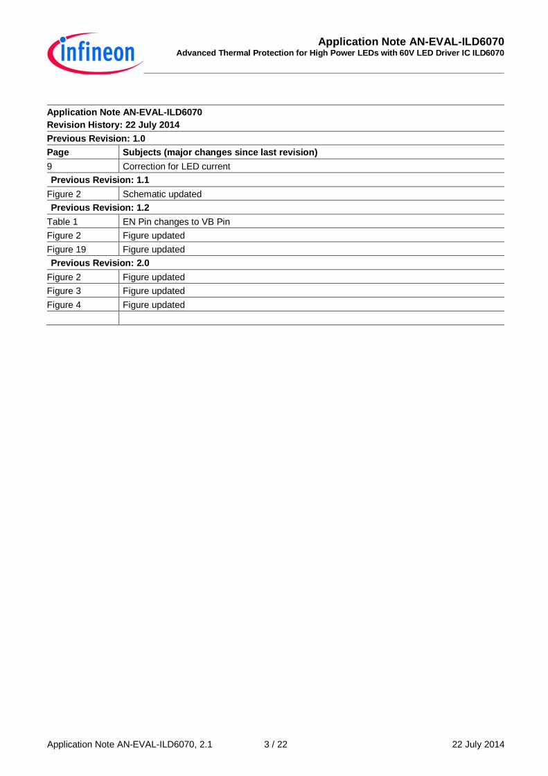
Application Note AN-EVAL-ILD6070
Revision History: 22 July 2014
Previous Revision: 1.0
Page Subjects (major changes since last revision)
9 Correction for LED current
Previous Revision: 1.1
Figure 2 Schematic updated
Previous Revision: 1.2
Table 1 EN Pin changes to VB Pin
Figure 2 Figure updated
Figure 19 Figure updated
Previous Revision: 2.0
Figure 2 Figure updated
Figure 3 Figure updated
Figure 4 Figure updated
ILD6070 Advanced Thermal Protection for High Power LEDs with 60V LED Driver IC ILD6070
List of Tables
Application Note AN-EVAL-ILD6070, 2.1 22 July 2014 4 / 22
Table of Contents
1 Introduction ................................................................................................................................... 5
2 Application Information ................................................................................................................ 6
3 Measurement Results ................................................................................................................... 9
4 References .................................................................................................................................. 21
List of Figures
Figure 1 ILD6070 .......................................................................................................................................... 5 Figure 2 Schematic of the demonstration board ............................................................................................ 6 Figure 3 PCB layout of the demonstration board ........................................................................................... 7 Figure 4 PCB photo of the demonstration board ............................................................................................ 7 Figure 5 Normal operation waveforms. .......................................................................................................... 9 Figure 6 Output LED current vs supply voltage. ........................................................................................... 10 Figure 7 Analog dimming ratio vs PWM pin voltage ..................................................................................... 10 Figure 8 Output waveforms at VPWM = 1 V. .................................................................................................. 11 Figure 9 Output waveforms at VPWM = 2 V. .................................................................................................. 11 Figure 10 Contrast ratio definitions ................................................................................................................ 12 Figure 11 Contrast ratio – PWM and LED current waveforms. ....................................................................... 13 Figure 12 Over Temperature Protection. ....................................................................................................... 14 Figure 13 Efficiency vs Supply voltage. ......................................................................................................... 14 Figure 14 LED current at the transition from DC to switch mode. ................................................................... 15 Figure 15 Soft start with 10 µF at the PWM pin.............................................................................................. 16 Figure 16 Average of LED current during the soft start with 10 µF at the PWM pin. ....................................... 17 Figure 17 Over current protection waveforms. ............................................................................................... 18 Figure 18 Thermal resistance of PCB-FR4 versus ground copper area.......................................................... 19 Figure 19 Thermal sensing with NTC thermistor. ........................................................................................... 20
List of Tables
Table 1 Bill-of-Materials ............................................................................................................................... 8 Table 2 Typical condition for measurement .................................................................................................. 9 Table 3 Contrast ratio calculation ............................................................................................................... 13
Application Note AN-EVAL-ILD6070 Advanced Thermal Protection for High Power LEDs with 60V LED Driver IC ILD6070
Application Note AN-EVAL-ILD6070, 2.1 22 July 2014 5 / 22
1 Introduction
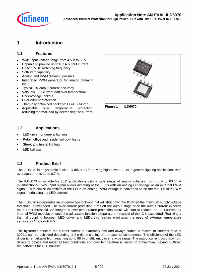
1.1 Features
Wide input voltage range from 4.5 V to 60 V
Capable to provide up to 0.7 A output current
Up to 1 MHz switching frequency
Soft-start capability
Analog and PWM dimming possible
Integrated PWM generator for analog dimming input
Typical 3% output current accuracy
Very low LED current drift over temperature
Undervoltage lockout
Over current protection
Thermally optimized package: PG-DSO-8-27
Adjustable over temperature protection, reducing thermal load by decreasing the current
Figure 1 ILD6070
1.2 Applications
LED driver for general lighting
Retail, office and residential downlights
Street and tunnel lighting
LED ballasts
1.3 Product Brief
The ILD6070 is a hysteretic buck LED driver IC for driving high power LEDs in general lighting applications with average currents up to 0.7 A. The ILD6070 is suitable for LED applications with a wide range of supply voltages from 4.5 V to 60 V. A multifunctional PWM input signal allows dimming of the LEDs with an analog DC voltage or an external PWM signal. To minimize colorshifts of the LEDs an analog PWM voltage is converted to an internal 1.6 kHz PWM signal modulating the LED current.
The ILD6070 incorporates an undervoltage lock-out that will shut down the IC when the minimum supply voltage threshold is exceeded. The over-current protection turns off the output stage once the output current exceeds the current threshold. An integrated over-temperature protection circuit will start to reduce the LED current by internal PWM modulation once the adjustable junction temperature threshold of the IC is exceeded. Realizing a thermal coupling between LED driver and LEDs this feature eliminates the need of external temperature sensors as NTCs or PTCs.
The hysteretic concept the current control is extremely fast and always stable. A maximum contrast ratio of 3000:1 can be achieved depending of the dimensioning of the external components. The efficiency of the LED driver is remarkable high, reaching up to 98 % of efficiency over a wide range. The output current accuracy from device to device and under all load conditions and over temperature is limited to a minimum, making ILD6070 the perfect fit for LED ballasts.
Application Note AN-EVAL-ILD6070 Advanced Thermal Protection for High Power LEDs with 60V LED Driver IC ILD6070
Application Note AN-EVAL-ILD6070, 2.1 22 July 2014 6 / 22
2 Application Information
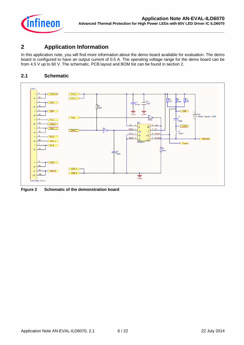
In this application note, you will find more information about the demo board available for evaluation. The demo board is configured to have an output current of 0.5 A. The operating voltage range for the demo board can be from 4.5 V up to 60 V. The schematic, PCB layout and BOM list can be found in section 2.
2.1 Schematic
Figure 2 Schematic of the demonstration board
Application Note AN-EVAL-ILD6070 Advanced Thermal Protection for High Power LEDs with 60V LED Driver IC ILD6070
Application Note AN-EVAL-ILD6070, 2.1 22 July 2014 7 / 22
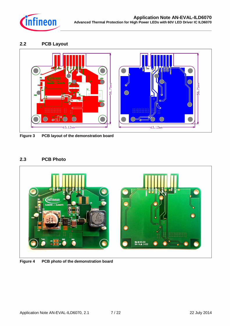
2.2 PCB Layout
Figure 3 PCB layout of the demonstration board
2.3 PCB Photo
Figure 4 PCB photo of the demonstration board
Application Note AN-EVAL-ILD6070 Advanced Thermal Protection for High Power LEDs with 60V LED Driver IC ILD6070
Application Note AN-EVAL-ILD6070, 2.1 22 July 2014 8 / 22
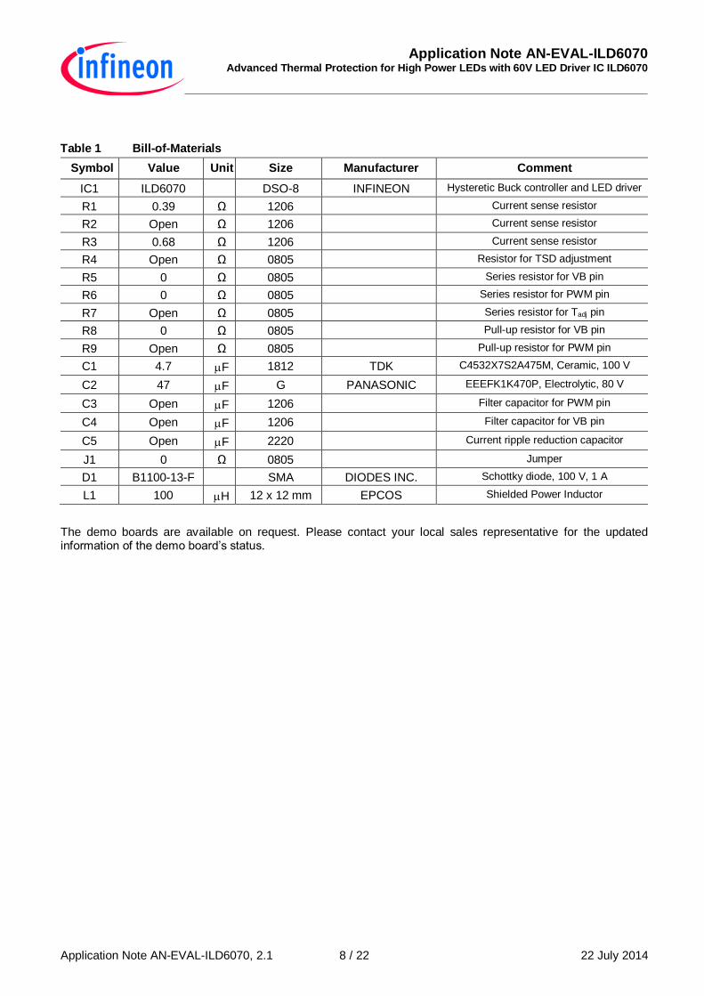
Table 1 Bill-of-Materials
Symbol Value Unit Size Manufacturer Comment
IC1 ILD6070 DSO-8 INFINEON Hysteretic Buck controller and LED driver
R1 0.39 Ω 1206 Current sense resistor
R2 Open Ω 1206 Current sense resistor
R3 0.68 Ω 1206 Current sense resistor
R4 Open Ω 0805 Resistor for TSD adjustment
R5 0 Ω 0805 Series resistor for VB pin
R6 0 Ω 0805 Series resistor for PWM pin
R7 Open Ω 0805 Series resistor for Tadj pin
R8 0 Ω 0805 Pull-up resistor for VB pin
R9 Open Ω 0805 Pull-up resistor for PWM pin
C1 4.7 F 1812 TDK C4532X7S2A475M, Ceramic, 100 V
C2 47 F G PANASONIC EEEFK1K470P, Electrolytic, 80 V
C3 Open F 1206 Filter capacitor for PWM pin
C4 Open F 1206 Filter capacitor for VB pin
C5 Open F 2220 Current ripple reduction capacitor
J1 0 Ω 0805 Jumper
D1 B1100-13-F SMA DIODES INC. Schottky diode, 100 V, 1 A
L1 100 H 12 x 12 mm EPCOS Shielded Power Inductor
The demo boards are available on request. Please contact your local sales representative for the updated information of the demo board’s status.
Application Note AN-EVAL-ILD6070 Advanced Thermal Protection for High Power LEDs with 60V LED Driver IC ILD6070
Application Note AN-EVAL-ILD6070, 2.1 22 July 2014 9 / 22
3 Measurement Results
3.1 LED current vs supply voltage
The average LED current is determined by the value of the external current sense resistor (Rsense), formed by
R1, R2 and R3 connected between Vs and Vsense. For ILD6070, the mean current sense threshold voltage is
125mV. The equation that determines the output LED current is given:
The target current setting for the demo board is 0.5 A. Based on above equation the Rsense is equal to 0.25 Ω.
Two resistors with the value of 0.39 Ω and 0.68 Ω in parallel are chosen for the demo board.
The measurement results in this section are based on the condition below, unless otherwise specified:
Table 2 Typical condition for measurement
Vs Rsense Inductance LED load
48 V 0.248 Ω 100 µH 12 pcs
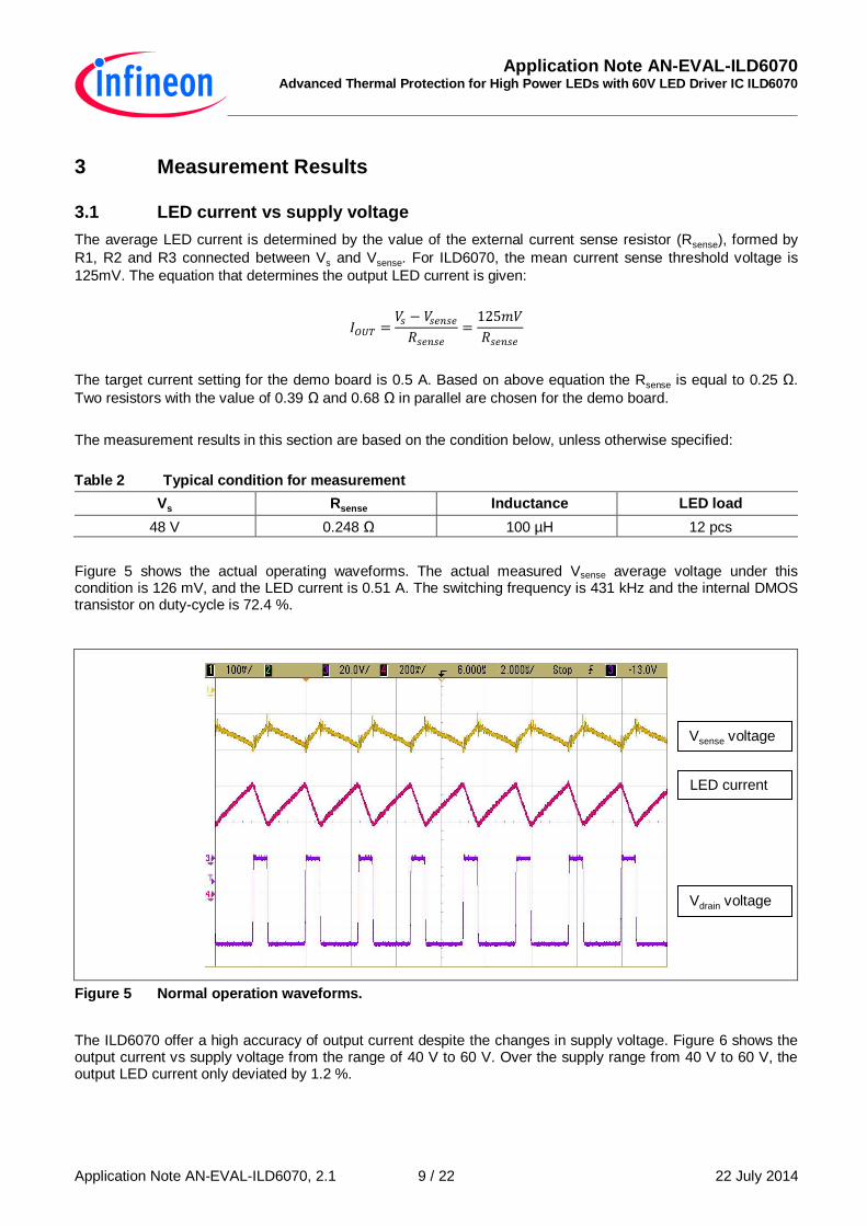
Figure 5 shows the actual operating waveforms. The actual measured Vsense average voltage under this condition is 126 mV, and the LED current is 0.51 A. The switching frequency is 431 kHz and the internal DMOS transistor on duty-cycle is 72.4 %.
Figure 5 Normal operation waveforms.
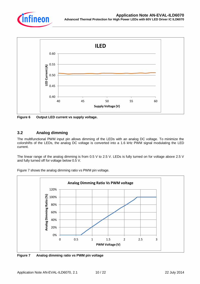
The ILD6070 offer a high accuracy of output current despite the changes in supply voltage. Figure 6 shows the output current vs supply voltage from the range of 40 V to 60 V. Over the supply range from 40 V to 60 V, the output LED current only deviated by 1.2 %.
Vsense voltage
LED current
Vdrain voltage
Application Note AN-EVAL-ILD6070 Advanced Thermal Protection for High Power LEDs with 60V LED Driver IC ILD6070
Application Note AN-EVAL-ILD6070, 2.1 22 July 2014 10 / 22
Figure 6 Output LED current vs supply voltage.
3.2 Analog dimming
The multifunctional PWM input pin allows dimming of the LEDs with an analog DC voltage. To minimize the colorshifts of the LEDs, the analog DC voltage is converted into a 1.6 kHz PWM signal modulating the LED current.
The linear range of the analog dimming is from 0.5 V to 2.5 V. LEDs is fully turned on for voltage above 2.5 V and fully turned off for voltage below 0.5 V.
Figure 7 shows the analog dimming ratio vs PWM pin voltage.
Figure 7 Analog dimming ratio vs PWM pin voltage
0.40
0.45
0.50
0.55
0.60
40 45 50 55 60
LED
Cu
rre
nt
(A)
Supply Voltage (V)
ILED
0%
20%
40%
60%
80%
100%
120%
0 0.5 1 1.5 2 2.5 3
An
alo
g D
imm
ing
Rat
io (
%)
PWM Voltage (V)
Analog Dimming Ratio Vs PWM voltage
Application Note AN-EVAL-ILD6070 Advanced Thermal Protection for High Power LEDs with 60V LED Driver IC ILD6070
Application Note AN-EVAL-ILD6070, 2.1 22 July 2014 11 / 22
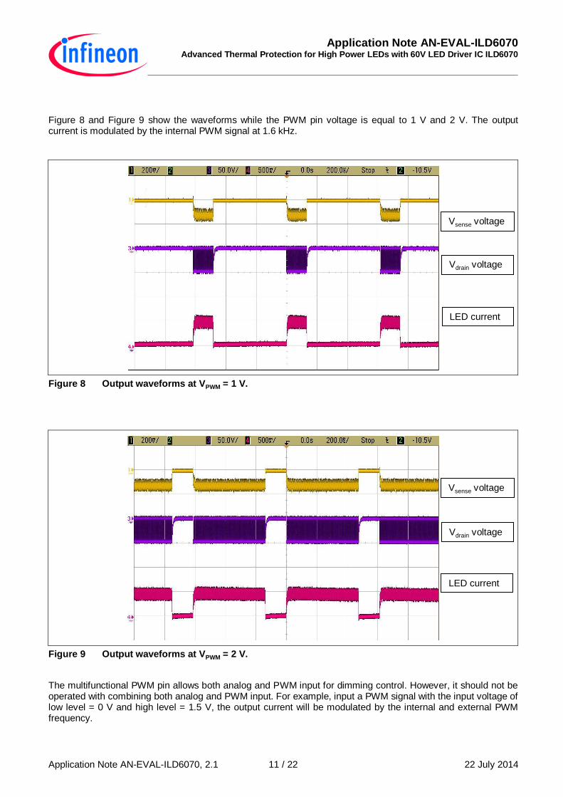
Figure 8 and Figure 9 show the waveforms while the PWM pin voltage is equal to 1 V and 2 V. The output current is modulated by the internal PWM signal at 1.6 kHz.
Figure 8 Output waveforms at VPWM = 1 V.
Figure 9 Output waveforms at VPWM = 2 V.
The multifunctional PWM pin allows both analog and PWM input for dimming control. However, it should not be operated with combining both analog and PWM input. For example, input a PWM signal with the input voltage of low level = 0 V and high level = 1.5 V, the output current will be modulated by the internal and external PWM frequency.
Vsense voltage
Vdrain voltage
LED current
Vsense voltage
Vdrain voltage
LED current
Application Note AN-EVAL-ILD6070 Advanced Thermal Protection for High Power LEDs with 60V LED Driver IC ILD6070
Application Note AN-EVAL-ILD6070, 2.1 22 July 2014 12 / 22
3.3 Contrast ratio
The contrast ratio of a system depends on the dimensioning of the external components, PWM frequency as well as supply voltage. The definition of the contrast ratio (CR) is given as:
Where
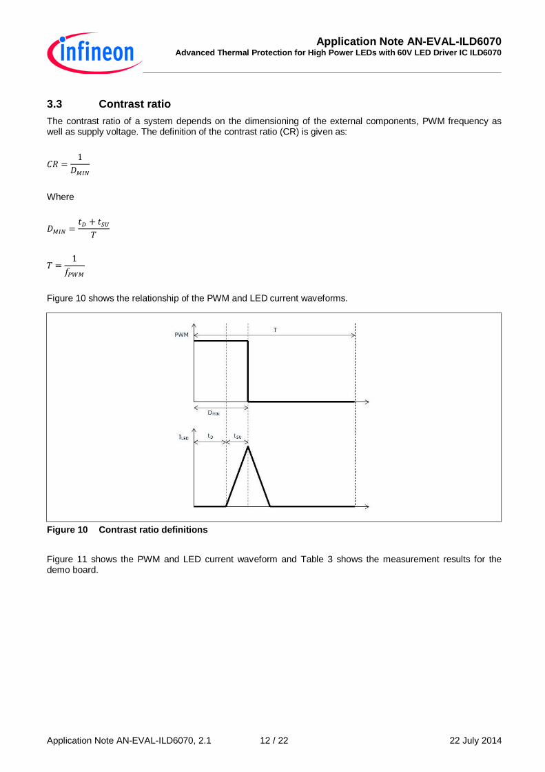
Figure 10 shows the relationship of the PWM and LED current waveforms.
Figure 10 Contrast ratio definitions
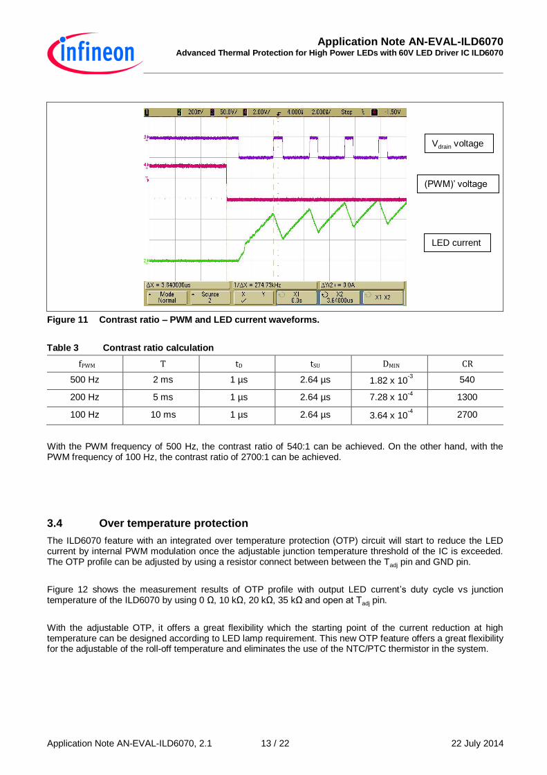
Figure 11 shows the PWM and LED current waveform and Table 3 shows the measurement results for the demo board.
Application Note AN-EVAL-ILD6070 Advanced Thermal Protection for High Power LEDs with 60V LED Driver IC ILD6070
Application Note AN-EVAL-ILD6070, 2.1 22 July 2014 13 / 22
Figure 11 Contrast ratio – PWM and LED current waveforms.
Table 3 Contrast ratio calculation
fPWM T tD tSU DMIN CR
500 Hz 2 ms 1 µs 2.64 µs 1.82 x 10⁻³ 540
200 Hz 5 ms 1 µs 2.64 µs 7.28 x 10⁻⁴ 1300
100 Hz 10 ms 1 µs 2.64 µs 3.64 x 10⁻⁴ 2700
With the PWM frequency of 500 Hz, the contrast ratio of 540:1 can be achieved. On the other hand, with the PWM frequency of 100 Hz, the contrast ratio of 2700:1 can be achieved.
3.4 Over temperature protection
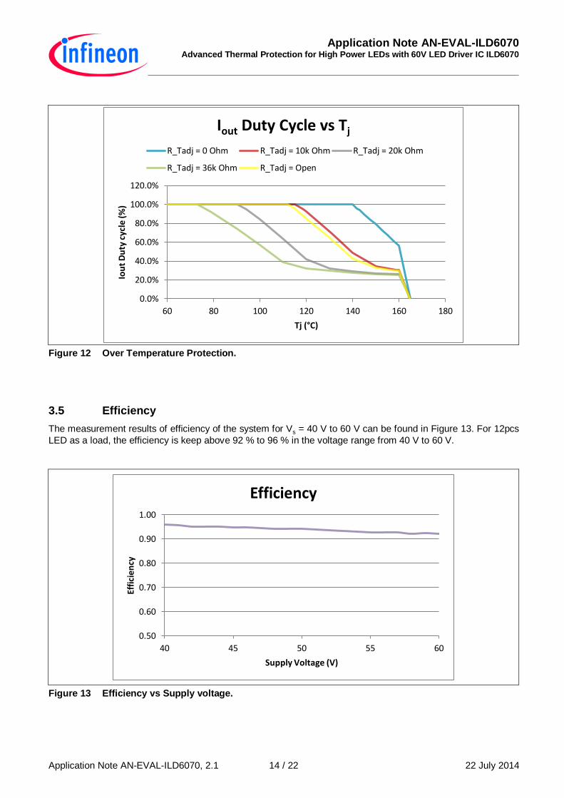
The ILD6070 feature with an integrated over temperature protection (OTP) circuit will start to reduce the LED current by internal PWM modulation once the adjustable junction temperature threshold of the IC is exceeded. The OTP profile can be adjusted by using a resistor connect between between the Tadj pin and GND pin.
Figure 12 shows the measurement results of OTP profile with output LED current’s duty cycle vs junction temperature of the ILD6070 by using 0 Ω, 10 kΩ, 20 kΩ, 35 kΩ and open at Tadj pin.
With the adjustable OTP, it offers a great flexibility which the starting point of the current reduction at high temperature can be designed according to LED lamp requirement. This new OTP feature offers a great flexibility for the adjustable of the roll-off temperature and eliminates the use of the NTC/PTC thermistor in the system.
Vdrain voltage
(PWM)’ voltage
LED current
Application Note AN-EVAL-ILD6070 Advanced Thermal Protection for High Power LEDs with 60V LED Driver IC ILD6070
Application Note AN-EVAL-ILD6070, 2.1 22 July 2014 14 / 22
Figure 12 Over Temperature Protection.
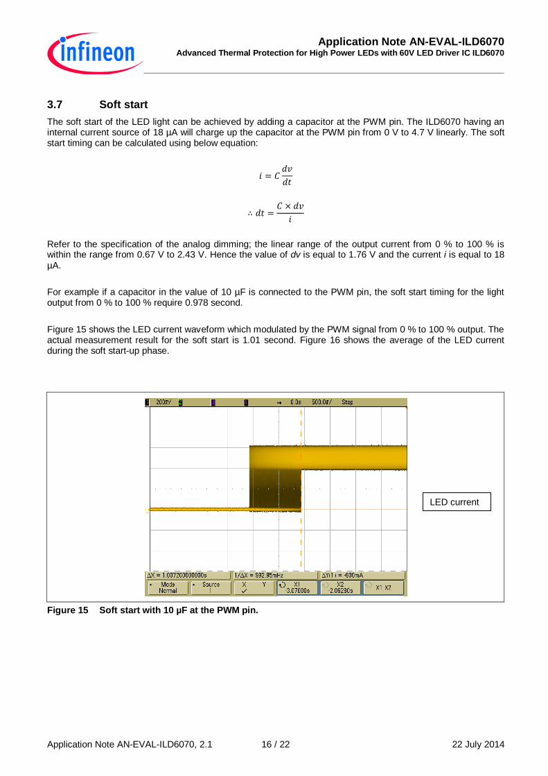
3.5 Efficiency
The measurement results of efficiency of the system for Vs = 40 V to 60 V can be found in Figure 13. For 12pcs
LED as a load, the efficiency is keep above 92 % to 96 % in the voltage range from 40 V to 60 V.
Figure 13 Efficiency vs Supply voltage.
0.0%
20.0%
40.0%
60.0%
80.0%
100.0%
120.0%
60 80 100 120 140 160 180
Iou
t D
uty
cyc
le (%
)
Tj (°C)
Iout Duty Cycle vs Tj
R_Tadj = 0 Ohm R_Tadj = 10k Ohm R_Tadj = 20k Ohm
R_Tadj = 36k Ohm R_Tadj = Open
0.50
0.60
0.70
0.80
0.90
1.00
40 45 50 55 60
Effi
cien
cy
Supply Voltage (V)
Efficiency

Application Note AN-EVAL-ILD6070 Advanced Thermal Protection for High Power LEDs with 60V LED Driver IC ILD6070
Application Note AN-EVAL-ILD6070, 2.1 22 July 2014 15 / 22
3.6 Transition from DC to switch mode
While the input supply voltage is lesser or close to the LEDs load forward voltage’s requirement, the output current is not reaching the target setting value. Under this condition, the ILD6070 is working in the DC mode, meaning that the DMOS is fully turned on and no switching activities.
One of the nice features that ILD6070 offer is during the transition from the DC mode to switch mode, it will not have any overshoot in the output current.
Figure 14 shows the LED current measurement results for the entire operating voltage range from 4.5 V to 60 V, Rsense = 0.178 Ω with different number of LEDs as load.
Figure 14 LED current at the transition from DC to switch mode.
Application Note AN-EVAL-ILD6070 Advanced Thermal Protection for High Power LEDs with 60V LED Driver IC ILD6070
Application Note AN-EVAL-ILD6070, 2.1 22 July 2014 16 / 22
3.7 Soft start
The soft start of the LED light can be achieved by adding a capacitor at the PWM pin. The ILD6070 having an internal current source of 18 µA will charge up the capacitor at the PWM pin from 0 V to 4.7 V linearly. The soft start timing can be calculated using below equation:
Refer to the specification of the analog dimming; the linear range of the output current from 0 % to 100 % is within the range from 0.67 V to 2.43 V. Hence the value of dv is equal to 1.76 V and the current i is equal to 18 µA.
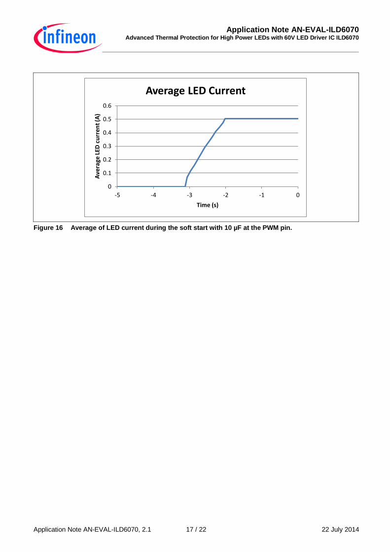
For example if a capacitor in the value of 10 µF is connected to the PWM pin, the soft start timing for the light output from 0 % to 100 % require 0.978 second.
Figure 15 shows the LED current waveform which modulated by the PWM signal from 0 % to 100 % output. The actual measurement result for the soft start is 1.01 second. Figure 16 shows the average of the LED current during the soft start-up phase.
Figure 15 Soft start with 10 µF at the PWM pin.
LED current
Application Note AN-EVAL-ILD6070 Advanced Thermal Protection for High Power LEDs with 60V LED Driver IC ILD6070
Application Note AN-EVAL-ILD6070, 2.1 22 July 2014 17 / 22
Figure 16 Average of LED current during the soft start with 10 µF at the PWM pin.
0
0.1
0.2
0.3
0.4
0.5
0.6
-5 -4 -3 -2 -1 0
Ave
rage
LED
cu
rre
nt
(A)
Time (s)
Average LED Current
Application Note AN-EVAL-ILD6070 Advanced Thermal Protection for High Power LEDs with 60V LED Driver IC ILD6070
Application Note AN-EVAL-ILD6070, 2.1 22 July 2014 18 / 22
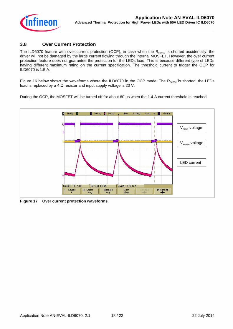
3.8 Over Current Protection
The ILD6070 feature with over current protection (OCP), in case when the Rsense is shorted accidentally, the driver will not be damaged by the large current flowing through the internal MOSFET. However, the over current protection feature does not guarantee the protection for the LEDs load. This is because different type of LEDs having different maximum rating on the current specification. The threshold current to trigger the OCP for ILD6070 is 1.5 A.
Figure 16 below shows the waveforms where the ILD6070 in the OCP mode. The Rsense is shorted, the LEDs load is replaced by a 4 Ω resistor and input supply voltage is 20 V.
During the OCP, the MOSFET will be turned off for about 60 µs when the 1.4 A current threshold is reached.
Figure 17 Over current protection waveforms.
Vdrain voltage
Vsense voltage
LED current
Application Note AN-EVAL-ILD6070 Advanced Thermal Protection for High Power LEDs with 60V LED Driver IC ILD6070
Application Note AN-EVAL-ILD6070, 2.1 22 July 2014 19 / 22
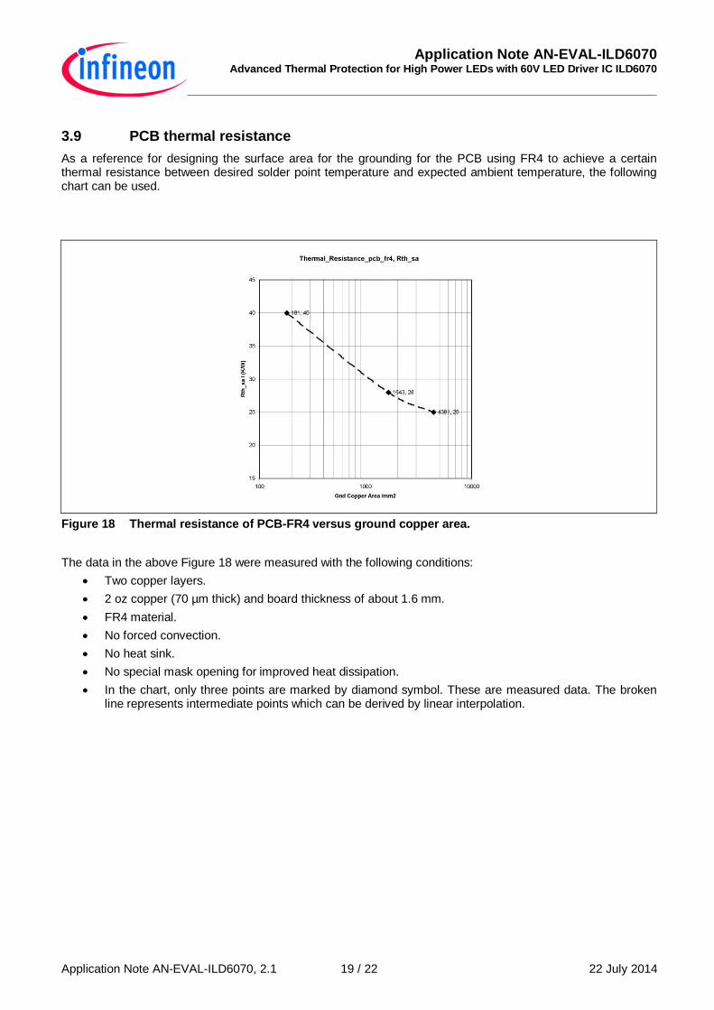
3.9 PCB thermal resistance
As a reference for designing the surface area for the grounding for the PCB using FR4 to achieve a certain thermal resistance between desired solder point temperature and expected ambient temperature, the following chart can be used.
Figure 18 Thermal resistance of PCB-FR4 versus ground copper area.
The data in the above Figure 18 were measured with the following conditions:
Two copper layers.
2 oz copper (70 µm thick) and board thickness of about 1.6 mm.
FR4 material.
No forced convection.
No heat sink.
No special mask opening for improved heat dissipation.
In the chart, only three points are marked by diamond symbol. These are measured data. The broken line represents intermediate points which can be derived by linear interpolation.
Application Note AN-EVAL-ILD6070 Advanced Thermal Protection for High Power LEDs with 60V LED Driver IC ILD6070
Application Note AN-EVAL-ILD6070, 2.1 22 July 2014 20 / 22
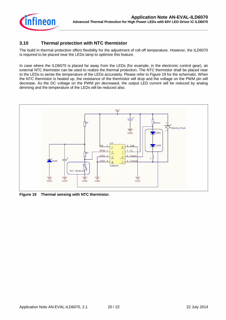
3.10 Thermal protection with NTC thermistor
The build in thermal protection offers flexibility for the adjustment of roll-off temperature. However, the ILD6070 is required to be placed near the LEDs lamp to optimize this feature.
In case where the ILD6070 is placed far away from the LEDs (for example, in the electronic control gear), an external NTC thermistor can be used to realize the thermal protection. The NTC thermistor shall be placed near to the LEDs to sense the temperature of the LEDs accurately. Please refer to Figure 19 for the schematic. When the NTC thermistor is heated up, the resistance of the thermistor will drop and the voltage on the PWM pin will decrease. As the DC voltage on the PWM pin decreased, the output LED current will be reduced by analog dimming and the temperature of the LEDs will be reduced also.
Figure 19 Thermal sensing with NTC thermistor.
Application Note AN-EVAL-ILD6070 Advanced Thermal Protection for High Power LEDs with 60V LED Driver IC ILD6070
Application Note AN-EVAL-ILD6070, 2.1 22 July 2014 21 / 22
4 References
Please refer to the ILD6070 Datasheet for more information:
Link to ILD6070 Data sheet

w w w . i n f i n e o n . c o m
Published by Infineon Technologies AG AN-EVAL-ILD6070