advanced test equipment rentals - atecorp.com · theory of insulation testing ... and maintenance...
TRANSCRIPT

AVTM22-15Ja Rev A
May 2005
15 kV DC Dielectric Test Set
Catalog No. 220015 Series
HIGH-VOLTAGE EQUIPMENT PLEASE READ CAREFULLY BEFORE OPERATING
Safety is the responsibility of the user
APARATO DE VOLTAJE ALTO SIRVANSE LEER ESTE LIBRO CON CUIDADO
ANTES OE OPERARLO La seguridad es el cargo del operador
M
Advanced Test Equipment Rentalswww.atecorp.com 800-404-ATEC (2832)
®
Established 1981

Copyright 1985-2005 by Megger. All rights reserved.
The information presented in this manual is believed to be adequate for the intended use of the product. If the product or its individual instruments are used for purposes other than those specified herein, confirmation of their validity and suitability must be obtained from Megger. Specifications are subject to change without notice.
M Megger Valley Forge Corporate Center 2621 Van Buren Avenue Norristown, PA 19403-2329 USA Tel: 610-676-8500 Fax: 610-676-8610 www.megger.com

i AVTM22-15Ja Rev. A May 2005
Table of Contents
1 INTRODUCTION.....................................................................................1
2 SAFETY PRECAUTIONS.......................................................................3
3 RECEIVING INSTRUCTIONS.............................................................7
4 SPECIFICATIONS....................................................................................9
5 DESCRIPTION ....................................................................................... 15 General.......................................................................................................15 Electrical ....................................................................................................15 Power Supply Option..............................................................................17 Overcurrent and Overvoltage Trip .......................................................18
6 CONTROL AND CONNECTOR IDENTIFICATION ............... 25
7 SETTING UP........................................................................................... 27 Preparation ................................................................................................27 Selection of Location...............................................................................27 Connections Procedure ...........................................................................28 Clearances..................................................................................................29 Power Supply Option, Catalog No. 220015-47...................................30
8 OPERATION........................................................................................... 35 Test Procedure..........................................................................................35 Breakdown of Test Item .........................................................................36 Normal Shutdown Procedure ................................................................37 Interrupting a Test ...................................................................................37
9 OPERATION NOTES........................................................................... 39 Line Voltage ..............................................................................................39 Meter Range Settings During Transit....................................................39 Stabilizing Switch......................................................................................40 Stabilizing Switch (-50 Option)..............................................................40 Use of Guard.............................................................................................41 Voltage Control Scale ..............................................................................41 Use of Regulation Curve (-50 Option) .................................................42 Step Voltage Testing................................................................................42 Fault Locating (Breakdown Testing).....................................................42 External Current Meter...........................................................................44

M
ii AVTM22-15Ja Rev. A May 2005
10 APPLICATION NOTES......................................................................47 Theory of Insulation Testing ................................................................. 47 Applying the Test Set to Grounded Test Object................................ 48 Three-Terminal vs. Two-Terminal Tests............................................. 49 Measuring an Ungrounded Test Item................................................... 49 Generalized Combined 2 and 3 Terminal Measurement................... 51
11 ROUTINE MAINTENANCE .............................................................53 Introduction.............................................................................................. 53 Inspection and Maintenance Procedure............................................... 53
12 TROUBLESHOOTING AND REPAIR..........................................57 General ...................................................................................................... 57 Case Repairs.............................................................................................. 58 Repairs to Components of Chassis And Panel ................................... 58 Changing Line Voltage Tap (-47 Models Only).................................. 59 Replacement of Output Cable W101.................................................... 59 Replacement of Meters or Meter Amplifier Board ............................ 60 Replacement of Current Meter Range Circuit..................................... 60 Replacement of Voltmeter Range Circuit ............................................ 60 Replacement of Stabilizing Switch S1................................................... 61 Replacement of Circuit Breakers........................................................... 61 Replacement of Voltage Control Autotransformer T1...................... 62 Replacement of the K2 Assembly ......................................................... 62 Replacement of Chassis-Mounted Assemblies.................................... 62 Replacement of Circuit Card U2........................................................... 63 Calibration of Voltmeter......................................................................... 63 Calibration of Current Meter ................................................................. 64 Adjustment of R1 in Stabilization Network (-50 Option)................. 66 Catalog No. 220015-50 ........................................................................... 66 Catalog No. 220015-47,-50..................................................................... 67 Trouble Location Chart .......................................................................... 68
13 PERFORMANCE CHECK.................................................................73
14 PARTS LIST............................................................................................75
15 WARRANTY AND REPAIRS............................................................77 Warranty.................................................................................................... 77 Repairs ....................................................................................................... 77

iii AVTM22-15Ja Rev. A May 2005
List of Figures
Figure a: The Megger Catalog No. 220015 DC Dielectric Test Set.........2
Figure 1: Schematic Diagram of Catalog No. 220015............................. 19
Figure 2: Schematic Diagram of Catalog No. 220015-50....................... 20
Figure 3: Schematic Diagram of Catalog No. 220015-42....................... 21
Figure 4: Schematic Diagram of Catalog No. 220015-43....................... 22
Figure 5: Schematic Diagram of Catalog No. 220015-101..................... 23
Figure 6A: Overall View of Catalog No. 220015..................................... 25
Figure 6B: Panel View of Catalog No. 220015......................................... 26
Figure 7: Testing in a Substation................................................................. 31
Figure 8: Testing Parking Lot Lighting; the Test Set Shown is Operating from an Inverter ....................................................... 32
Figure 9: Testing Transformer Terminals. ............................................... 33
Figure 10: DC Motor test setup................................................................. 34
Figure 11: Generator test setup.................................................................. 34
Figure 12: Regulation Curves with Stabilizer "out", 120V Supply, -50 Option. ................................................................................ 44
Figure 13: Typical Guard Connection to Cable Pothead........................ 45
Figure 14: Guard Connection for a Typical Cable Test.......................... 45
Figure 15: Typical Guard Connection for an Oil Circuit Breaker......... 46
Figure 16: Typical Guard Connection for Transformer Test ................ 46
Figure 17: Two-Winding Transformer in Three-Terminal Form.......... 50
Figure 18: Interior Views. ........................................................................... 70
Figure 19: Connections for Calibration of Voltmeter............................. 71
Figure 20: Connections for Calibration of the Current Meter............... 71

M
iv AVTM22-15Ja Rev. A May 2005
List of Tables
Table 1: Minimum Air Clearances..............................................................29 Table 2: Measurements of Resistance........................................................50
Table 3: Trouble Location............................................................................68
1 AVTM22-15Ja Rev. A May 2005
1
INTRODUCTION
This instruction manual is intended as a guide to the operation and maintenance of the portable Dielectric Test Set, Megger Catalog No. 220015 series.* References in this manual to optional functions and equipment may be disregarded when such information does not apply to the Test Set in use.
The instructions and suggestions provided in this manual anticipate the normal use of the Dielectric Test Set for testing electrical insulation systems on such equipment as motors, generators, bushings and cables. These tests which are based on measurement of the applied dc voltage, the resulting current and the manner in which current varies with time, provide data that indicate the condition of the insulation system of the unit being tested. When these data are recorded on graph paper, such as Megger Kilovolt-Megohm Paper (Part No. 220000), the shape of the curve made by connecting the plotted points will aid in evaluating the conditions of the insulation system. Information on the interpretation of observed data and guides for test voltage and time are given in Section 10 of this manual.
The basic available options covered by this manual are:
-42 Adjustable overcurrent trip setting on microammeter.
-43 Adjustable overvoltage trip setting on kilovoltmeter.
-47 Operation from input line voltage other than nominal 115 volts (Specify voltage from 100 to 240 volts).
-50 Internal voltage stabilization circuits to suppress input transient voltages.
* This manual is intended for use with sets manufactured after January 1985.

M
2 AVTM22-15Ja Rev. A May 2005
Figure a: The Megger Catalog No. 220015 DC Dielectric Test Set

3 AVTM22-15Ja Rev. A May 2005
2
SAFETY PRECAUTIONS
SAFETY IS THE RESPONSIBILITY OF THE USER LA SEGURIDAD ES LA RESPONSABILIDAD DEL OPERADOR
The Test Set and the equipment to which it is connected are a source of high-voltage electrical energy. All persons performing or assisting in the tests must use all practical safety precautions to prevent contact with energized parts of the test equipment and associated circuits. Persons actually engaged in the test must stand clear of all parts of the complete high-voltage circuit unless the Test Set is de-energized and all parts of the test circuit are grounded. Persons not directly associated with the work must be kept away from test activities by suitable barriers, barricades or warnings.
The Test Set panel must be connected to a reliable local ground to prevent possible shock danger to the operator. Since the energized test setup may induce a static voltage charge on nearby insulated objects, including people, all insulated objects must be grounded or kept at least two feet (61 cm) from the energized structure.
G CAUTION!
Never connect the Test Set to energized equipment or use the Test Set in an explosive atmosphere.
All apparatus to be tested should be bonded to ground except during the actual test. Note that even isolated conductors may develop static voltage with respect to ground due to nearby electric fields, wind friction or passing electrified clouds. Test connections should be made with the ground bonds in place.

M
4 AVTM22-15Ja Rev. A May 2005
At the completion of a test, after the power source has been shut down and the Test Set kilovoltmeter reads zero, all energized parts of the test setup must be short-circuited by means of a safety grounding stick (hot stick). Ground bonds should then be applied to the equipment that was tested. These bonds should be left in place until access to the equipment is again required.
If the Test Set is operated in accordance with the safety precautions noted above and in Sections 7 and 8, and if all grounds are correctly made, rubber gloves are not necessary. As a routine safety procedure however, some users require that rubber gloves be worn not only when making connections to the high-voltage terminals, but also when manipulating controls. Megger considers this an excellent safety practice.
Megger strongly recommends the general safety practices contained in IEEE Std. 510 "IEEE Recommended Practices for Safety in High-Voltage and High-Power Testing" as a guide for all high-voltage testing. Do not, however, use this standard to reduce any of the precautions given in this manual.
HEART PACEMAKERS
High-voltage discharges and other sources of strong electric or magnetic fields may interfere with the proper functioning of heart pacemakers. Personnel using heart pacemakers should obtain expert advice on the possible risks before operating this equipment or being close to the equipment during operation.
OTHER PRECAUTIONS
§ Be especially careful when testing apparatus having high capacitance such as cables. These items store a dangerous charge, even at low voltage.
§ Identify apparatus terminals and verify apparatus ground prior to making connections.

SAFETY PRECAUTIONS
5 AVTM21-415Ja Rev. A May 2005
F WARNING!
Do not use the Cat. No. 220015 Series Test Set for any purpose not described in this Instruction Manual, and do not use accessory items (cables, grounding sticks, etc.) for any purpose except with the specified equipment.
§ Read and follow the instruction manual.

M
6 AVTM22-15Ja Rev. A May 2005
M

7 AVTM22-15Ja Rev. A May 2005
3
RECEIVING INSTRUCTIONS
When your instrument arrives, check the equipment received against the packing list to ensure that all materials are present. Notify:
Megger Valley Forge Corporate Center 2621 Van Buren Avenue Norristown, PA 19403 U.S.A. 610.676.8500
of any shortage of materials.
Examine the instrument for damage received in transit. If any damage is discovered, file a claim with the carrier at once and notify Megger or its nearest authorized sales representative, giving a detailed description of the damage observed.
This instrument has been thoroughly tested and inspected to meet rigid inspection specifications before being shipped. It is ready for use when set up as indicated in Section 7.
A qualified person should become familiar with this entire Manual and make a test run. This pre-test serves both to familiarize the user with the Test Set and to check that the set is operating properly.

M
8 AVTM22-15Ja Rev. A May 2005
M

9 AVTM22-15Ja Rev. A May 2005
4
SPECIFICATIONS
POWER SUPPLY: Catalog No. 220015
Voltage (rms): 105 -130 Volts
Recommended Source: NEC 15 Ampere, 120 Volts, single-phase branch circuit (3 wire: line, neutral and ground).
Current (rms): 1.5 Amps, maximum continuous.
Frequency: 60 Hz, full rating 50 Hz, reduced rating
Basis of Rated performance:
120-Volt, 60 Hz supply with stabilizer out.
OPTIONAL SUPPLY: Catalog No. 220015-47
Voltage (rms): Specify nominal voltage on order.
Current (rms): NOMINAL RANGE MAXIMUM CURRENT
210 208 to 225 0.80
230 225 to 240 0.83
250 240 to 265 0.85
Recommended Source: 10-Ampere, nominal voltage, single-phase branch circuit.
Frequency: 60 Hz full rating; 50 Hz reduced rating.
Basis of Rated performance:
230 Volt, 60 Hz supply with stabilizer out.
M
10 AVTM22-15Ja Rev. A May 2005
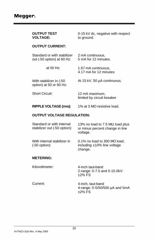
OUTPUT TEST VOLTAGE:
0-15 kV dc, negative with respect to ground.
OUTPUT CURRENT:
Standard or with stabilizer out (-50 option) at 60 Hz:
2 mA continuous, 5 mA for 12 minutes.
at 50 Hz: 1.67 mA continuous, 4.17 mA for 12 minutes
With stabilizer in (-50 option) at 50 or 60 Hz:
At 15 kV, 50 µA continuous.
Short Circuit: 12 mA maximum, limited by circuit breaker
RIPPLE VOLTAGE (rms): 1% at 3 MO resistive load.
OUTPUT VOLTAGE REGULATION:
Standard or with internal stabilizer out (-50 option):
13% no load to 7.5 MΩ load plus or minus percent change in line voltage.
With internal stabilizer in (-50 option):
0.1% no load to 300 MO load, including ±10% line voltage change.
METERING:
Kilovoltmeter: 4-inch taut-band 2-range: 0-7.5 and 0-15.0kV: ±2% FS
Current: 4-inch, taut-band 4-range: 0-5/50/500 µA and 5mA ±2% FS

SPECIFICATIONS
11 AVTM21-415Ja Rev. A May 2005
CONTROLS:
Power OFF-ON switch (Circuit Breaker) with green lamp indicator.
High-voltage OFF-ON switch (Circuit Breaker) with red lamp indicator.
Voltage control with Zero-Start interlock, 0-100 reference dial.
Stabilizer selector switch: IN-OUT.
Voltmeter Range Switch: 7.5-15 kV.
Ammeter multiplier switch, 4-position: x1, x10, x100, x1K
CABLES and CONNECTORS
Power Supply Cord: 7½ feet (2.3 meters), 3-wire with plug
Output Cable: Attached; shielded with GUARD terminal, high-voltage clip and boot; 15 feet (4.6 meters) long.
Ground Cable: Separate, 10 feet (3.3 meters) with positive action clamp at outboard end.
Ground Terminal: ¼ inch stud with wing nut.
External Instrument Jack: Accepts ¼ inch 2-wire phone plug for connecting external recorder or current meter to read current in test item.

M
12 AVTM22-15Ja Rev. A May 2005
PHYSICAL:
Case: High-impact structural foam, polycarbonate plastic with metal control panel and removable hinged lid.
Size: Overall Width Depth Height
20 ½ 12 13 inches 52 30.5 33 cm
Weight:
Catalog No. 220015: 35 ¼ lbs. (16 kg)
Catalog No. 220015-47: 39 ½ lbs. (18 kg)
Instruction Card: Permanently attached inside lid.
Cable & Manual Storage: Fit in compartment in case.
ENVIRONMENT:
Temperature: 0°F (-17.7°C) to 122°F (50°C) maximum operating.
Altitude: 10,000 feet (3,048 meters) maximum operating.
Relative Humidity: Non-condensing conditions.
Shock and Vibration: Will withstand normal shock and vibration encountered in field use and transportation.
PROTECTIVE FEATURES:
Dual overload protection for all overload conditions by two separate circuit breakers. Metering protected against overload and transient conditions.

SPECIFICATIONS
13 AVTM21-415Ja Rev. A May 2005
SAFETY FEATURES:
"Zero start" interlock: Voltage Control must be at zero to enable the output voltage circuit to be energized (started).
Grounded metal control panel.
Separate visible panel ground cable.
Permanently attached shielded output cable.
Separate switches for control power and high-voltage output.

M
14 AVTM22-15Ja Rev. A May 2005
M

15 AVTM22-15Ja Rev. A May 2005
5
DESCRIPTION
GENERAL
This portable Dielectric Test Set measures the electrical quantities of applied voltage and resultant current in the apparatus to which it is connected. Designed for field or shop use, the complete Test Set (including all leads) is housed in a durable, impact-resistant plastic case, with removable lid and carrying strap. For safety in operation, the control panel of the Test Set is of grounded metal.
ELECTRICAL
The Test Set consists of a variable dc power supply with metering of the output voltage and current passing between the high-voltage output terminal and ground.
Figure 1 is the schematic diagram of this Test Set (see page 19).
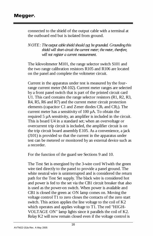
The high-voltage dc power supply is contained within an internal guard shield. The output of the step-up transformer T101 supplies a full-wave voltage-doubling rectifier consisting of protective resistors R107 and R108, the silicon rectifiers CR101 and CR102 and the output filter capacitors C101 and C102. For safety the power supply is discharged by the bleeder resistors R101 and R102. Resistor R104 limits the output current if the apparatus being tested breaks down. Resistor R103 is the kilovoltmeter multiplier and capacitor C103 protects the voltmeter from transients. The negative terminal of the power supply is the high-voltage output and is connected to the center conductor of output cable W101. The positive terminal of the power supply is used as a guard and is
M
16 AVTM22-15Ja Rev. A May 2005
connected to the shield of the output cable with a terminal at the outboard end but is isolated from ground.
NOTE: The output cable shield should not be grounded. Grounding this shield will short-circuit the current meter; the meter, therefore, will not register a current measurement.
The kilovoltmeter M101, the range selector switch S101 and the two range calibration resistors R105 and R106 are located on the panel and complete the voltmeter circuit.
Current in the apparatus under test is measured by the four-range current meter (M-102). Current meter ranges are selected by a front panel switch that is part of the printed circuit card U1. This card contains the range selector resistors (R1, R2, R3, R4, R5, R6 and R7) and the current meter circuit protection elements (capacitor C1 and Zener diodes CR1 and CR2). The current meter has a sensitivity of 100 µA. To obtain the required 5 µA sensitivity, an amplifier is included in the circuit. This is board U4 in a standard set; when an overvoltage or overcurrent trip circuit is included, the amplifier circuit is on the trip circuit board assembly E105. As a convenience, a jack (J101) is provided so that the current in the apparatus under test can be metered or monitored by an external device such as a recorder.
For the function of the guard see Sections 9 and 10.
The Test Set is energized by the 3-wire cord W1with the green wire tied directly to the panel to provide a panel ground. The white neutral wire is uninterrupted and is considered the return path for the Test Set supply. The black wire is considered hot and power is fed to the set via the CB1 circuit breaker that also is used as the power-on switch. When power is available and CB1 is closed the green ac ON lamp comes on. Moving the voltage control T1 to zero closes the contacts of the zero start switch. This action applies the line voltage to the coil of K2 which operates and applies voltage to T1. The red "HIGH-VOLTAGE ON" lamp lights since it parallels the coil of K2. Relay K2 will now remain closed even if the voltage control is

DESCRIPTION
17 AVTM21-415Ja Rev. A May 2005
advanced off its zero position. Raising the voltage control now applies a controlled voltage to the primary of T101 through the trip coil of circuit breaker switch CB2.
Line voltage transients may cause the ammeter pointer to swing widely, interfering with measurement. A stabilizing (meter damping) switch S102 and a capacitor C104 are provided so that by placing the switch in the IN position (closed), the capacitor will increase the meter damping and cause the meter to integrate and slow the pointer swings. When the stabilizing switch is in the OUT position, minimum integration occurs and the motion of the meter pointer is normal (see Sections 8 and 9 for additional information).
When the -50 option is built-in, the line voltage is fed to T1 through the stabilization selector switch S1 directly, when S1 is closed in the OUT position.
When S1 is set to the "IN" position (stabilized) voltage is applied to T1 through resistor R1 and a parallel path exists from the input of T1 to the circuit return through the back-to-back connected Zener diodes CR1 and CR2. These diodes clip the peaks of the voltage across T1 so that any transient changes in the line supply voltage do not change the crest amplitude. This stabilizes the output voltage as long as the load current does not exceed 50 µA (see Figure 2).
The primary circuit breaker CB1 is the ac line switch and protects T1 and the elements of the control circuit. The circuit breaker CB2 acts as the OUTPUT ON switch and protects T1 to its allowable output current.
POWER SUPPLY OPTION
Test sets equipped with -47 optional input differ from standard sets in that separate step-down transformers T2 and T3 are included between the power source and the Test Set (see Figure 1). The nominal line voltage is specified at purchase. Transformers are located in the lid of the Test Set.

M
18 AVTM22-15Ja Rev. A May 2005
Optional supply voltages may be selected by wiring the transformer assembly in accordance with the table shown in Figure 1.
OVERCURRENT AND OVERVOLTAGE TRIP (See Fig. 3, 4 or 5 Schematics)
The basic circuitry and general operation of all sets, including those provided with optional features, is as previously described. The overcurrent and overvoltage options consist of modifications of the respective meters; and since these options work on the same principle, the following is applicable to both.
On sets which include either or both of the optional features noted above, the appropriate meter has been modified to include a circuit that senses the input quantity corresponding to the position of the meter pointer. The meter is additionally equipped with a red pointer which may be set to any position on the scale by means of a small manual control knob on the meter. When the position of the meter pointer coincides with that of the red pointer, the circuit responds by tripping a meter relay. This relay includes a set of contacts that are normally closed while the meter pointer rests between zero and the red pointer. However, when the meter pointer reaches the red pointer, the relay contacts open. This opens the coil circuit of K-2 and thereby removes power from the Test Set. For sets equipped with both the overcurrent and overvoltage options, both meter relay contacts are in series so that if either voltage or current limits (as set by the respective red pointers) are exceeded, the Test Set is de-energized (for exact limits of operation, see Section 8). After a tripout occurs, the voltage control must be returned to zero before Test Set output can be obtained.

DESCRIPTION
19 AVTM21-415Ja Rev. A May 2005
Figure 1: Schematic Diagram of Catalog No. 220015

M
20 AVTM22-15Ja Rev. A May 2005
Figure 2: Schematic Diagram of Catalog No. 220015-50
DESCRIPTION
21 AVTM21-415Ja Rev. A May 2005
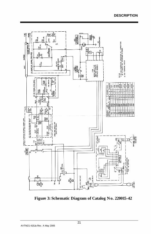
Figure 3: Schematic Diagram of Catalog No. 220015-42

M
22 AVTM22-15Ja Rev. A May 2005
Figure 4: Schematic Diagram of Catalog No. 220015-43

DESCRIPTION
23 AVTM21-415Ja Rev. A May 2005
Figure 5: Schematic Diagram of Catalog No. 220015-101

M
24 AVTM22-15Ja Rev. A May 2005
M

25 AVTM22-15Ja Rev. A May 2005
6
CONTROL and CONNECTOR IDENTIFICATION
1 Guard Terminal 6. Instruction Card
2. Output Cable 7. Carrying Strap
3. High Voltage Terminal 8. Removable Case Cover
4. Ground Cable 26. Location of -47 Option Step-Down Transformer
5. Power Cord 27. Lead Storage
Figure 6A: Overall View of Catalog No. 220015

M
26 AVTM22-15Ja Rev. A May 2005
2. Output Cable 15. 7.5 kV Voltmeter Calibrator
5. Power Cord 16. Kilovoltmeter Range Selector
9. External Instrument Jack 17. 15 kV Voltmeter Calibrator
10. Ammeter Calibrator 18. Voltage Control
11. Ammeter Multiplier Selector 19. AC "ON" Green Lamp
12. Ammeter 20. Input Power Switch
13. Stabilization Selector 21. Output "ON" Red Lamp
14. Kilovoltmeter 22. Output "ON" Switch
24. Panel Ground
Figure 6B: Panel View of Catalog No. 220015

27 AVTM22-15Ja Rev. A May 2005
7
SETTING UP
Test set controls and terminals are identified in Section 6. The following steps are listed as a general guide for setting up the Dielectric Test Set. Suggested setup arrangements are shown in Figures 7 through 11.
PREPARATION
Before setting up the test equipment, read Section 2, SAFETY. Working with due regard to safety, identify the terminals of the apparatus to be tested. Be sure that the low voltage terminal is securely grounded. Provide a ground connection, if necessary, using wire of 18 AWG or larger.
Define the type of test required; references listed in Sections 9 and 10.
Place guard connections on the terminals if a guarded test is required (see Sections 8 and 9). Set up barriers or use other means to keep unauthorized personnel away from all high-voltage terminals of the complete test arrangement.
SELECTION OF LOCATION
Select a location for the Test Set which meets the following conditions:
1. The operating area must be as dry as possible.
2. The Test Set must be within 15 feet of the high-voltage terminal of the apparatus to be tested.

M
28 AVTM22-15Ja Rev. A May 2005
NOTE: For operator safety, the output cable should be fully extended to provide maximum distance between the operator and the high-voltage terminal.
3. A reliable ground connection must be within 12 feet of the Test Set.
4. If an electrical service outlet is not within range of the input cable, a UL-approved extension cord rated for 15 amperes (minimum) and not longer than 50 feet may be used.
5. The operator of the Test Set must be able to conduct the test without being exposed to traffic hazard; the operator must have free access to all controls and be able to read the meters and panel markings easily without approaching energized high-voltage terminals.
CONNECTIONS PROCEDURE
1. Connect the Test Set ground lead to the panel and to the local ground.
G CAUTION!
For safe operation this separate ground cable must be used. The green wire of the input cable provides a parallel path but cannot be relied on to provide an adequate ground path for the panel.
2. Connect the output cable clip to the high-voltage terminal of the apparatus to be tested (see below under Clearances).
3. If guard is not in use the output cable shield must not be grounded. Grounding this shield will short-circuit the ammeter; the set, therefore, will not register a current measurement.
4. If a guarded test is to be run, connect the guard lead of the apparatus to be tested to the shield of the output cable (see Sections 8 and 9). Insulate the guard circuit from ground.

SETTING UP
29 AVTM21-415Ja Rev. A May 2005
5. With the Test Set switch OFF, connect the power cord to the service outlet.
CLEARANCES
Be sure adequate clearances are maintained between energized conductors and ground to prevent arc-over. Such accidental arc-over may create a safety hazard or damage the equipment being tested. The position of the exposed conductors with respect to ground can often be maintained by tying the conductors in place with clean, dry nylon rope. Table 1 lists the minimum air clearances that must be maintained and also suggests the minimum path length along a rope if it is tied directly to a conductor. Finally, the table indicates minimum personnel clearances (based on OSHA specifications) that will limit the danger of static induced voltages being developed on nearby insulated objects, including people.
TABLE 1: MINIMUM AIR CLEARANCES
Voltage of Test
Direct Air Path
(inches)
Path Along Dry Nylon Rope
(inches)
Minimum Personnel Clearances
(feet)
5 kV 0.5 11/8 2
10 kV 1.0 2 ¼ 2
15 kV 1.5 4 2
After completion, make a careful review of the test setup. Tests can then be conducted per Section 8. For convenience a condensed operating procedure is given on the Instruction Card.

M
30 AVTM22-15Ja Rev. A May 2005
POWER SUPPLY OPTION, Catalog No. 220015-47
Test Sets with Optional Features
Test sets equipped with either the overcurrent or overvoltage options, or both, are set up as previously described; however, before conducting a test, the desired limits of voltage and/or current should be set in accordance with the instructions given in Section 8.
When the equipment has been set up according to the above procedure, tests can be conducted in accordance with the instructions given in Section 8. An operator familiar with these tests and with the Test Set in use can follow the operating procedures given in abbreviated form on the lid of the Test Set.

SETTING UP
31 AVTM21-415Ja Rev. A May 2005
Figure 7: Testing in a Substation.

M
32 AVTM22-15Ja Rev. A May 2005
Figure 8: Testing Parking Lot Lighting; the Test Set Shown is Operating from an Inverter

SETTING UP
33 AVTM21-415Ja Rev. A May 2005
Figure 9: Testing Transformer Terminals.

M
34 AVTM22-15Ja Rev. A May 2005
Figure 10: DC Motor test setup.
Figure 11: Generator test setup.

35 AVTM22-15Ja Rev. A May 2005
8
OPERATION
When the Test Set and apparatus to be tested are set up as indicated in Section 7, the equipment can be energized and the required tests run by following the steps given below.
NOTE: Before operating the Dielectric Test Set, read Section 2 of this manual and ensure that all appropriate safety precautions are observed.
Before conducting a test, consult Section 9 for details that may pertain to the test being conducted. For information on test theory, see Section 10. For a performance check, see Section 13.
TEST PROCEDURE
1. Remove all safety grounds from the apparatus to be tested.
2. Close the AC "ON" switch; green lamp comes on.*
* If the service outlet voltage exceeds the rated limit for the Test Set, the Power "ON" indicator will be abnormally bright. This will warn and alert the operator to stop the procedure and correct the problem.
3. Close the OUTPUT "ON" switch.
4. Set the voltmeter range switch to desired range.
5. Set ammeter MULTIPLIER switch to X1K range.
6. Set Stabilizer to "OUT" position.
7. Firmly move voltage control to zero; red lamp comes on.

M
36 AVTM22-15Ja Rev. A May 2005
8. Turn voltage control clockwise to increase output voltage as required for test being conducted.
9. Note voltage, resistance and time as required by the test procedure being followed. Make settings and take readings as described in steps below.
10. If indicated current fluctuates during the reading, the stabilizing switch may be set to the "IN" position (see Section 9).
11. Follow the same operating procedure for Test Sets equipped with overvoltage and/or overcurrent options; but prior to energizing the test, set the red pointer on the appropriate meter to the desired limit. For a more exact setting, set the red pointer to maximum, then energize the Test Set using all necessary safety procedures so that the required trip level is obtained. Lower the red pointer until the set trips out. Proceed with desired testing.
12. Follow the same operating procedure for Test Sets equipped with the 230V 50/60 Hz option. Operation of sets with this option is identical except for the supply line voltage.
BREAKDOWN OF TEST ITEM
In the event of failure of the apparatus being tested, the Test Set circuit breakers will trip out within twenty (20) seconds. When the stabilizer is in use trip-out may not occur but the output current is limited to 7.5 mA. When such a trip-out occurs, before approaching the equipment, apply the grounding stick to the high-voltage terminal to discharge the test setup as all stored energy may not be dissipated by such a failure.
OPERATION
37 AVTM21-415Ja Rev. A May 2005
NORMAL SHUTDOWN PROCEDURE
When the test has been completed, follow this shutdown procedure:
1. Set the voltage control to zero.
2. Open the AC "ON" switch or the OUTPUT "ON" switch or both.
3. When the voltmeter indicates that voltage has decreased to a value of less than half the voltage used during the test, use an insulated grounding stick to apply a direct short circuit to all ungrounded terminals of the apparatus being tested.
4. Disconnect cables in the following sequence; first, the input cable; second, the output cable (including the guard if in use), finally, the ground cable.
5. Apply ground bonds to the equipment that has been disconnected.
INTERRUPTING A TEST
At any time, the AC "ON" or HV "ON" switches can be opened manually to interrupt a test, provided that the grounding stick is applied afterward to discharge any stored energy as described in the normal shutdown procedure.
For any circumstances requiring that a test be stopped immediately, the procedure is to apply the grounding stick directly to the high-voltage terminal. This action will remove the test voltage in the shortest possible time. If the stabilizer is out the AC "ON" or HV "ON" circuit breakers will trip or they can be operated manually. If the stabilizer is "IN" it is necessary to open either the HV "ON" or the AC "ON" switches manually to permanently de-energize the test. This procedure should be followed only when absolutely necessary since there is a risk of damage to both the Test Set and the apparatus being tested.

M
38 AVTM22-15Ja Rev. A May 2005
M

39 AVTM22-15Ja Rev. A May 2005
9
OPERATION NOTES
LINE VOLTAGE
In field service, it is frequently necessary to use a temporary power service. Recognizing that such a service may accidentally be connected cross-phase or may be of improper voltage, the Test Set has been equipped with a POWER ON lamp placed on the electrical circuitry after the input circuit breaker. When the glow of the POWER ON lamp is abnormally bright, the operator is quickly warned (before he attempts to obtain high-voltage output) that the line voltage is incorrect and may correct the problem before any damage is done to the Test Set.
Megger recommends that when using the Cat. No. 220015-47, the service supplying the Test Set be protected by a fuse of not less than 1¼ ampere or more than 3 amperes.
The Catalog No. 220015-47 has been supplied with a line cord connector for which adapters are readily available to fit the many different service outlets in use. The connector may be cut off and replaced with the fitting used in the service area if desired. The green lead must connect to service ground, the white lead to the supply neutral and the black lead to the "hot" lead of the supply.
METER RANGE SETTINGS DURING TRANSIT
The meters included in this set are of rugged construction, but it is recommended that during transportation of the Test Set the meter range switches be set to the highest range (the voltmeter to 15 kV, the current meter to 5 mA) and the stabilizing switch placed in the IN position.

M
40 AVTM22-15Ja Rev. A May 2005
STABILIZING SWITCH
This switch acts on the current meter circuit only. During the measurement of leakage current on apparatus having significant capacitance, small line voltage transients can result in large transient swings of the current meter. This effect will be most noticeable when using the 5 µA range and will require that the operator judge the indicated current value by visually and mentally averaging the value. To assist in this, the meter stabilizing feature and/or a line voltage conditioner ahead of the Test Set may be used. Placing the meter stabilizing switch to the IN position will cause the meter to integrate and so average the current over a period of time. This helps the operator to judge the value by reducing the number of pointer swings and slowing down the pointer motion. With the stabilizing switch set to OUT, the meter follows current variations most accurately to a limit set by the ballistic meter response. This feature is most useful for tests in which current is measured in relation to time, especially when times are on the order of minutes.
STABILIZING SWITCH (-50 Option)
In most cases the motion of the current meter pointer is slow and steady enough to permit a definite reading. In certain cases it will be observed to swing rapidly and widely so that a definite current reading cannot be made. This happens when the item under test has significant capacitance and resistance values on the order of thousands of megohms. It is the result of line voltage transients that cause small changes in the test voltage.
The readings can be significantly stabilized under these conditions by switching the stabilizer "IN" during the test, and readjusting the test voltage if necessary. The stabilizer is only effective if the current is less than 50 µA. The stabilizer can be "IN" for the complete test but the output voltage will take longer to reach its final value than if the stabilizer is "OUT".
OPERATION NOTES
41 AVTM21-415Ja Rev. A May 2005
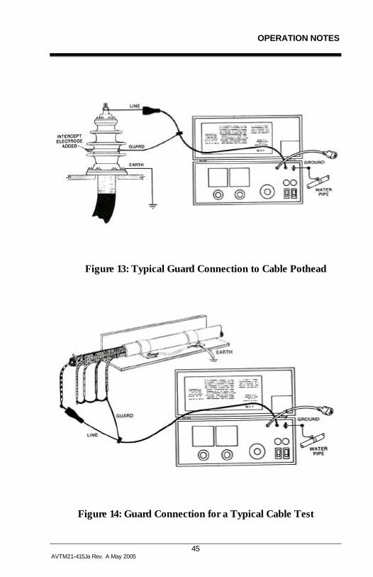
USE OF GUARD (see also Section 10)
Occasionally when measuring apparatus, the leakage resistance of interest is masked by a parallel path. Such a situation is often encountered when measuring the leakage current of a cable. In the practical situation, the value of the resistance along the leakage path from the conductor over the surface of the pothead may be less than that within the major length of the cable. Under such conditions the guard feature of the Test Set is useful in excluding the leakage of the surface path from the measurement (see Figures 13 and 14). This is easily accomplished, by forming an intercepting electrode by wrapping a bare wire around the outer surface of the cable pothead insulation close to the cable shield or ground. This wire electrode, which will intercept the surface current, must be connected to the Test Set guard terminal. The unwanted current then bypasses the current meter and is not measured; the meter will read only the current of the main portion of the cable.
The same guard principle can be used on other apparatus, (Figures 15 and 16) where a suitable intercepting electrode can be added on a temporary basis. On some kinds of apparatus, notably bushings, the guard electrode is built in.
The guard terminal is only a few volts about ground and does not pose a safety hazard; however, it must not be allowed to contact ground.
VOLTAGE CONTROL SCALE
A reference scale is provided so that the voltage control position can be repeated. This convenience feature is useful when making repetitive tests such as those required on the three-phase wires of a cable. In addition, the voltage control scale is used to predetermine the voltage developed even though the actual voltage buildup may lag behind the motion of the voltage control because of the capacitance charging effect. Using this feature minimizes the possibility of applying excessive voltage to the apparatus being tested.

M
42 AVTM22-15Ja Rev. A May 2005
To predetermine the voltage control setting, refer to the regulation curve given in Figure 12. The accuracy of the voltage setting will normally be on the order of 5 to 10%, depending on the line voltage and the nature of the apparatus being tested (see next paragraph).
USE OF REGULATION CURVE (-50 Option)
The regulation curve given in Figure 12 applies when the stabilizer is "OUT" and has been provided for convenience in planning the adaptation of the Test Set to measurement of various apparatus. It is also useful in adapting the Test Set to special use such as production testing. The regulation curve relates the output voltage control setting to the actual output voltage and load resistance. From this curve, peak ripple voltage can be estimated and the equivalent internal resistance of the Test Set can be estimated for a wide variety of circumstances. The curve also indicates the circuit breaker limit of operation.
STEP VOLTAGE TESTING
This Test Set is well adapted to the commonly used test procedure of increasing the voltage applied to the apparatus being tested in steps (see Section 10 for additional data). The regulation curve given in Figure 12 is useful for estimating in advance the voltage control position for each step. Then during the test, the control can be advanced to the next predetermined setting. This procedure gives the sharpest step change in voltage and provides better test results than if the control is inched to the next step.
FAULT LOCATING (BREAKDOWN TESTING)
In practice, if the apparatus being tested fails, the user may be faced with the problem of locating the failure so that repairs can be made. Often the failure occurs in the form of an arc-over; that is, the apparatus will support some voltage, but

OPERATION NOTES
43 AVTM21-415Ja Rev. A May 2005
above this level a spark forms at the failure, the voltage collapses, and the current soars.
This will usually trip out the Test Set; but if the voltage control is set just beyond the voltage that causes arc-over, it is possible that the arc-over will repeat several times before trip out. During this time, the operator can look for the light and noise generated by the spark and so locate the fault. Arc-over can be induced quite deliberately without damage to the Test Set; it is even possible to place some resistance in series with the high-voltage connection and allow the arc-over to periodically repeat and continue for long periods of time. In some cases, however, this result can be obtained simply by careful adjustment of the voltage control.
As an alternate, the stabilizer (-50 option) can be switched "IN" because it increases the time to charge a cable without the need of an external resistor. Trip-out will be avoided and the voltage control setting is not as critical.
This Test Set is not recommended for locating faults in long cables but it may be used occasionally for cable fault locating on short cables (on the order of 1000 ft. or less) that arcover at voltages of less than 15 kV.
In any case, when used for this purpose the Test Set can continue, for long periods, to generate arc-overs at a rate not exceeding one discharge every three seconds. Attempts to shorten this time interval may result in trip-out. Trip-out warns that the thermal limit of the components will shortly be reached unless the discharge rate is reduced by lowering the voltage or adding series resistance. When series resistance is added, care must be taken to avoid hazards from the new connection. When using the stabilizer in the "IN" position the voltage control should be set to comply with the discharge rate.

M
44 AVTM22-15Ja Rev. A May 2005
EXTERNAL CURRENT METER
To read or record the test current, connect a suitable instrument to a two-wire phone plug that mates with EXT. INST jack J1. The tip of the plug will be positive, the ring negative. The external meter impedance must not exceed 10,000 ohms. The meter should be protected against overcurrent transients.
Figure 12: Regulation Curves with Stabilizer "out", 120V Supply, -50 Option.
OPERATION NOTES
45 AVTM21-415Ja Rev. A May 2005
Figure 13: Typical Guard Connection to Cable Pothead
Figure 14: Guard Connection for a Typical Cable Test

M
46 AVTM22-15Ja Rev. A May 2005
Figure 15: Typical Guard Connection for an Oil Circuit Breaker
Figure 16: Typical Guard Connection for Transformer Test

47 AVTM22-15Ja Rev. A May 2005
10
APPLICATION NOTES
THEORY OF INSULATION TESTING
Any device that uses electrical energy can ordinarily be considered as consisting of elements that may be classified in two separate categories, namely, those parts of the apparatus that conduct the electrical energy and those parts that are not intended to conduct. It follows that any such apparatus includes an insulation system that is not intended to conduct electrical energy but which is under electrical stress. If such insulating parts do become conductive, the apparatus will fail. Electrical insulation can be tested by a variety of methods and measurements may be taken to anticipate such failures. Each method has its own merits, but one technique is to apply a dc voltage to the insulation system and measure such quantities as the applied voltage, the leakage current and the manner in which such quantities vary with time. These dc test techniques have been well developed over many years and considerable literature exists on this subject. Detailed information on dc testing is also available in a course entitled "DC Testing of Power Apparatus Insulation" offered by the AVO Training Institute.
The few references given below are not presented in any special order and no particular preference is implied; but they are included merely for the convenience of the user so that he may make full use of this Dielectric Test Set.
Fink, Donald G. and Carroll, John M. Standard Handbook for Electrical Engineers (New York: McGraw-Hill, 1968)
M
48 AVTM22-15Ja Rev. A May 2005
Guide for Testing Insulation Resistance of Rotating Machinery, IEEE Standard 43.
Guide for Insulation Maintenance for Large Alternating Current Rotating Machinery. IEEE Standard 46.
Guide for Making Dielectric Measurements in the Field. IEEE Standard 62.
Guide for Insulation Testing of Large AC Rotating Machinery with High Direct Voltage. IEEE Standard 95.
APPLYING THE TEST SET TO GROUNDED TEST OBJECT
The Test Set measures the test voltage and the current of the item under test; the operator must introduce the time parameter into the test.
For safety reasons, one terminal of the Test Set must be connected to ground. One side of the apparatus being tested must be connected to ground. This minimizes exposure of high-voltage leads and conforms to the way most apparatus is constructed. This leaves one terminal at high-voltage and for dc Test Sets this high-voltage lead is preferably negative with respect to ground.
The Test Set measures the test voltage and the current of the item connected across the two output terminals; that is, the high-voltage terminal and ground.
For most purposes the two-terminal current measurement is all that is required since all paths between High-Voltage (Line) and Ground (Earth) are simultaneously measured and a total value is found.

APPLICATION NOTES
49 AVTM21-415Ja Rev. A May 2005
THREE-TERMINAL vs. TWO-TERMINAL TESTS
There are certain important practical situations where a two-terminal measurement does not convey the desired information.
In Section 9 the guard was recommended when testing cable. In practical application, this arrangement can resolve the problem that the dirty surface path over the pothead may conduct more current to ground than actually passes through the bulk of the cable itself. The practical result is that the cable appears to have a relatively low resistance, while in fact, the cable itself is acceptable but the pothead is not.
By making an unguarded then a guarded test, it is possible to determine if the cable of the pothead is at fault thus indicating the appropriate action to be taken.
The principle of making more than one measurement with and without guard can be extended to other apparatus in order to separate multiple resistance paths and so better analyze the situation.
In some literature, the unguarded measurement is called a two-terminal measurement while the guarded measurement is called a three-terminal measurement.
The principle of combining 2 and 3 terminal measurements is often used when the path of interest does not have the required ground on one terminal in order to make the usual measurement.
MEASURING AN UNGROUNDED TEST ITEM
A two-winding transformer in a grounded metal case with the core also grounded is a common construction having the typical problem of measurement of an ungrounded path. Frequently it is desirable to test the insulation between each winding and ground and the insulation between the windings.

M
50 AVTM22-15Ja Rev. A May 2005
In Figure 17 this case is shown schematically, with the three insulation paths of interest shown as resistances.
Figure 17: Two-Winding Transformer in Three-Terminal Form.
It is convenient to treat each insulation measurement as a resistance reading; the equivalent resistance for each measurement is equal to the test voltage divided by the measured current. The measurements required are a combination of 2 and 3 terminal forms and measurements of resistance are made in accordance with Table 2.
TABLE 2: Measurements of Resistance CONNECTIONS
MEASUREMENT HIGH-VOLTAGE GROUND GUARD
r12’ 1 2 Not Used r12 1 2 3 r23 3 2 1
r12’(r12-r23)-r12r23 r13=
r12-r12’
By using the guard the resistance between each winding and ground is measured directly and with the addition of one extra measurement the resistance between windings is calculated from the above equation.
APPLICATION NOTES
51 AVTM21-415Ja Rev. A May 2005
NOTE: There are alternate forms possible for the desired equation and measurement table.
GENERALIZED COMBINED 2 and 3 TERMINAL MEASUREMENT
The schematic of Figure 17 is equivalent to three delta-connected resistors with one junction grounded. Many problems can be reduced to this form and then evaluated by the technique given above. The additional effort required to carry out the study to reduce the problem to a grounded delta form and then perform the necessary measurements are often justified for a preventative maintenance program that compares measurements made at long intervals, such as yearly. Another justification is usually related to how important the apparatus is and how reliable it must be.

M
52 AVTM22-15Ja Rev. A May 2005
M

53 AVTM22-15Ja Rev. A May 2005
11
ROUTINE MAINTENANCE
INTRODUCTION
Field service subjects high-voltage test equipment to a difficult environment but equipment wear can be minimized by periodic inspection and cleaning. Such inspections and cleaning will also ensure reliable on-the-job operation. The frequency of routine inspection and cleaning will depend on the field conditions encountered. As a guide, for sets operated indoors in a normally dusty atmosphere, this procedure should be performed once every six months; as an extreme, the procedure should be carried out monthly on a set that is used daily outdoors in a heavy dust concentration that is conductive and hygroscopic.
Prior to performing inspection and maintenance, consult any damage reports that may have been completed for the Test Set.
INSPECTION AND MAINTENANCE PROCEDURE
Complete inspection and maintenance procedures can be performed in approximately fifteen minutes. The only equipment required consists of a screwdriver, an insulated jumper about one foot long, a clean damp cloth, and a clean dry cloth.
Proceed according to the steps given below.
1. Visually inspect the case, noting that hinges and case locks function properly. Check for breaks in the case or lid. Note the condition of the carrying strap and case feet.

M
54 AVTM22-15Ja Rev. A May 2005
2. Wipe the outside of the case with the damp cloth; then dry with a clean dry cloth.
3. Open the lid; fully extend and visually inspect all cables. If necessary, wipe each cable with the damp cloth; then dry. Wipe out the lead compartment. Wipe the panel and instruction card with a clean dry cloth.
4. Visually inspect the panel, noting that all knobs are secure on their shafts and that all controls operate smoothly without binding.
5. Set meters mechanically to zero.
6. Removal of Test Set from Case
G CAUTION!
The Test Set must be de-energized for at least fifteen minutes before removing from case!
The Test Set should be removed from its case only by those trained in handling high-voltage equipment since high-voltage can be stored in components of the Test Set interior even after the set has been de-energized.
To remove the Test Set from the case, follow the procedure below:
A. Set aside the ground cable.
B. Remove and save the four panel screws.
C. Raise the panel straight up to clear the case. Handle the set only by the panel. Place the set on a clean surface.
D. Remove the guard screen, and using the insulated jumper, short circuit both capacitors C101 and C102 (see Figure 18 for identification).

ROUTINE MAINTENANCE
55 AVTM21-415Ja Rev. A May 2005
7. Completion of Inspection
A. Wipe the circuit card with a clean dry cloth to remove accumulated dust. Wipe the interior of the case. Visually inspect the interior connections and components.
B. Re-install the guard screens. Make sure that the rear screen fully clears the panel-mounted resistor R1 and that the front screen fully clears the Zener diodes CR1 and CR2.
C. Re-install the set in the case.
D. Coil the leads and replace them in the lead compartment.
If defects are discovered during this inspection see Section 12 for repair procedures. If all is in order, the performance may be checked by following the procedure given in Section 13.

M
56 AVTM22-15Ja Rev. A May 2005
M

57 AVTM22-15Ja Rev. A May 2005
12
TROUBLESHOOTING and REPAIR
GENERAL
Megger maintains a complete repair service and recommends that its customers take advantage of this service in the event of equipment malfunction. The instrument will be cleaned and excessively worn or damaged parts replaced. Following repair, the instrument will perform functionally like a new instrument, but the appearance will be substantially as returned. A new one-year warranty will be extended to those parts repaired.
For those users who prefer to make their own repairs, replacement parts are available from the factory. (Part numbers are given in Section 14). Those items which can be returned separately for repair are indicated in the parts list by an asterisk following the part number. Upon their return to the factory, such items will be repaired or replaced, whichever is less costly and returned to the user under the same conditions as new replacement parts.
Prior to shipment, all components supplied for field replacement are inspected to the same extent as those used in original equipment; but because of the possibility of related component failure, Megger does not warrant such assemblies. (Shipping damage, of course, is covered by insurance claims.)
If the Test Set fails to operate properly, the information given in this section will be useful in determining the cause of the malfunction. Table 3 (included at the end of this section) notes possible equipment malfunctions that may be observed during operation or performance check (see Section 13) and suggests possible causes and means of determining the defective

M
58 AVTM22-15Ja Rev. A May 2005
component. The schematic diagram in Section 5 and the interior view of the Test Set given in Figure 18 will be helpful in locating components. When ordering parts, always include the Test Set serial number. The location of the serial number is shown in Figure 18.
It is important that persons repairing the Test Set fully understand the operation of the circuitry. When an assembly fails, it may damage associated components and this possibility must be evaluated prior to replacing an assembly. The circuitry must also be understood so that measures may be taken to prevent shock hazard to those making repairs.
When making repairs in this Test Set or replacing components, the procedures outlined in the following paragraphs should be followed.
Remove the Test Set from the case as explained in Section 11.
CASE REPAIRS
Because of its construction, a damaged lid or lower case will require that both lid and lower case be replaced as a unit. The replacement case is supplied with the instruction card and all hardware so that the Test Set can simply be placed into it. The case feet, carrying strap, and strap loops are accessible for replacement after the Test Set has been removed from the case.
REPAIRS TO COMPONENTS OF CHASSIS AND PANEL
In most cases any work will require separating the panel and chassis.
To do this, follow steps below:
1. Remove both guard screens.
2. Locate the shield of the output cable and disconnect it from the chassis.

TROUBLESHOOTING & REPAIR
59 AVTM21-415Ja Rev. A May 2005
3. Carefully unsolder the output cable center conductor from the shield eyelet.
4. Mark all leads on the panel terminal strip and disconnect them.
5. Locate the four nuts that secure the chassis to the panel; with the set upright on the chassis remove the nuts, lock washers and flat washers.
6. Withdraw the four mounting stud insulating bushings.
7. Lift the panel off the chassis.
8. Set aside the insulation spacer blocks that are located between chassis and panel.
9. Follow these steps in reverse order for re-assembly.
CHANGING LINE VOLTAGE TAP (-47 MODELS ONLY)
To change the nominal supply voltage on the -47 version, disconnect the Test Set from the line. Remove the 4 screws securing the adapter to the lid. Re-connect taps per table listed in schematic and on the adapter (P/N 22763). Install fuse F1 of correct rating. Complete by re-installing adapter in lid.
REPLACEMENT OF OUTPUT CABLE W101
It is not necessary to separate panel and chassis for this operation. Remove Test Set from the case and remove the rear guard screen. Locate the output cable and carefully unsolder the center conductor from the shield eyelet. Remove the screw holding the outer shield to the chassis. With proper tool remove the cable and clamp bushing from the panel. If necessary loosen the circuit card so the cable will come free of the notch.
If the replacement cable is P/N 10586 the above procedure is reversed to install the replacement. If not, the replacement cable should be prepared to duplicate the original cable before installation.
M
60 AVTM22-15Ja Rev. A May 2005
REPLACEMENT OF METERS OR METER AMPLIFIER BOARD
1. Place the panel on a clean cloth with the meters face down.
2. Remove the leads and note the terminals to which they should be reconnected.
3. Remove amplifier board if necessary (current meter only).
4. Remove the four nuts and washers on the meter studs.
5. Slide the meter from the panel.
6. Replace the meter and reverse the above steps to complete the repair.
REPLACEMENT OF CURRENT METER RANGE CIRCUIT
1. Remove the range switch knob, switch shaft locknut and washer.
2. Unsolder the three leads attached to the U1 circuit card, noting the proper reconnection terminals for each lead.
3. Install the new U1 assembly.
4. Tighten the switch shaft nut.
5. Replace the knob so that the numbers line up with the panel index lines. Be sure that all steps are aligned.
6. Resolder the leads to the printed circuit card.
REPLACEMENT OF VOLTMETER RANGE CIRCUIT
1. Remove the voltmeter knob and the switch bushing nut.
2. Unsolder the three leads, noting where each one terminates.

TROUBLESHOOTING & REPAIR
61 AVTM21-415Ja Rev. A May 2005
3. Replace the switch assembly and tighten the switch bushing nut.
4. Replace the knob, align it with the panel index, then tighten the knob on the shaft.
5. Resolder the leads to the printed circuit card.
REPLACEMENT OF STABILIZING SWITCH S1
1. Separate panel and chassis.
2. Mark and remove the leads from the switch.
3. Carefully note the location of the notch in the switch shank.
4. Remove the defective switch.
5. Reverse the procedure to complete replacement.
REPLACEMENT OF CIRCUIT BREAKERS
1. Separate panel and chassis.
2. Locate defective unit.
3. Carefully mark and disconnect all leads from the defective unit.
4. Remove the two front panel screws and remove the circuit breaker.
5. Be sure the correct current rating is used for replacement.
6. Install with breaker closing when handle is pushed toward the rear of the set.
7. Reverse the procedure to complete replacement.

M
62 AVTM22-15Ja Rev. A May 2005
REPLACEMENT OF VOLTAGE CONTROL AUTOTRANSFORMER T1
1. Disconnect all leads, noting the appropriate reconnection terminal for each.
2. Remove the voltage control knob.
3. Remove the bushing nut.
4. Pull the transformer free of the assembly.
5. Replace the transformer through the panel.
6. Tighten the panel nut.
7. Reconnect the wires.
8. Install the knob and check its alignment at zero and full scale, then tighten.
REPLACEMENT OF THE K2 ASSEMBLY
1. Disconnect relay K2, noting the appropriate reconnection terminals for each wire.
2. Remove K2 from the panel bracket.
3. Replace K2.
4. Reconnect relay K2.
REPLACEMENT OF CHASSIS-MOUNTED ASSEMBLIES
To replace chassis mounted assemblies, remove the panel following the procedure given above and short-circuit the two capacitors, then follow the appropriate steps given below.

TROUBLESHOOTING & REPAIR
63 AVTM21-415Ja Rev. A May 2005
REPLACEMENT OF CIRCUIT CARD U2
1. Remove panel from chassis.
2. Remove 4 corner screws that secure the card to the chassis.
3. Lift card for access to wiring.
4. Cut or slide back the splice insulation to transformer lead.
5. Carefully unsolder the connection to free the transformer lead.
6. Mark and remove the leads connected to the capacitors.
7. Remove the screws holding the Zener diode heat sink assembly to the card.
8. Cut any tie-wrap and free card.
9. Re-assembly is the reverse of this procedure.
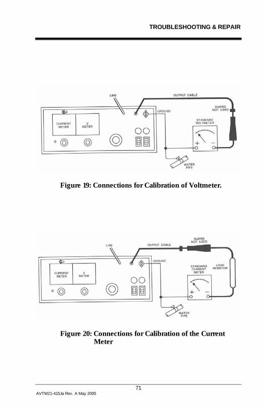
CALIBRATION OF VOLTMETER
This procedure requires a dc meter that is capable of reading both 7.5 kV and 15 kV with an accuracy of +1% or better. On either range this standard instrument should draw less than 0.5 mA. The Megger AC/DC 20 kV Kilovoltmeter, Cat. No. 513020 is recommended.
1. Connect the Test Set as shown in Figure 19.
2. Remove the cover screws from both the 7.5 kV CAL and the 15 kV CAL adjustments.
3. Operate the Test Set (Reference Section 8). Set its voltmeter range to 7.5kV.
4. Adjust the output voltage until the standard voltmeter reads 5.0 kV.

M
64 AVTM22-15Ja Rev. A May 2005
5. Using a fine blade screwdriver, adjust the 7.5 kV potentiometer through the 7.5 kV CAL hole until it agrees with the standard.
6. Check at 7.5 kV full scale, then repeat for the 15 kV range using the 15 kV CAL adjustment and an output of 10 kV. Check at 15 kV full scale.
7. Replace both CAL cover screws.
CALIBRATION OF CURRENT METER
The current meter calibration requires a standard dc current meter capable of measuring 5 µA to 5 mA to an accuracy of ±1% or better. Also required are the following testing resistors.
Desired Resistance and Tolerance
Voltage Watts Suggested Part No.
100 Megohms ±1% 500 <1 4694-12
10 Megohms ±1% 5000 2.5 (2) 4694-7, in parallel
2 Megohms ±5% 7000 25 (2) 4694-8, in parallel
With power off, adjust meter to zero. Check and correct any excessive leakage current using Steps 1, 2, 3 and 5 of Section 14.
Check the X1 range first. This checks the unshunted meter with current amplifier U4. There is no accessible adjustment. Proceed as follows for this check:
1. Make connections as shown in Figure 20 using 5 µA range on standard meter and 10-megohm resistor.
2. Operate the test. (Reference Section 8).
3. Set voltmeter range to 7.5 kV and current meter multiplier to X1.

TROUBLESHOOTING & REPAIR
65 AVTM21-415Ja Rev. A May 2005
4. Increase the output voltage until standard current meter indicates 5 µA (at almost 500 volts).
5. The Test Set meter should read 5 microamperes.
If the required accuracy is not met, the meter with amplifier U4 or its protective network may require repair. This must be done prior to calibration of the X10, X100 and X1000 ranges.
Next, adjust the X100 range using the CAL adjustment. (This adjustment applies also to the X10 and X1000 ranges). Proceed as follows:
1. Connect the 10-megohm load resistor and set multiplier to X100; set the standard range meter for 500 µA.
2. Increase output for a reading of 500 µA on the standard meter (at about 5 kV).
3. Adjust the Test Set microammeter calibrator (CAL) so that the meter reads 5. To make this adjustment, remove the CAL cover screw, and use a fine blade screwdriver to adjust the calibration control.
4. To check for tracking, reduce the voltage until the standard current meter reads 0.25 mA. The Test Set meter should then read 2.5 (half scale). Re-adjust CAL for the best compromise.
5. To check the X10 range:
A. Connect the 10-megohm resistor and set the current to 50 µA (at about 500 Volts).
B. The Test Set meter should read 5.
6. To check the X1000 range:
A. Connect the 2 MΩ resistor and set the current to 2.5 mA (about 5000 Volts).
B. The Test Set meter should read 2.5 (half scale).

M
66 AVTM22-15Ja Rev. A May 2005
ADJUSTMENT OF R1 IN STABILIZATION NETWORK (-50 OPTION)
The objective of this adjustment is to dissipate no more than 48 watts in the stabilizing Zener diodes CR1 and CR2 at maximum line voltage and minimum burden (output current) on the Test Set.
CATALOG NO. 220015-50
Remove the Test Set from the case. Locate R1 on the rear of the panel (see interior view Figure 18) and remove the rear guard screen. The power cord must be removed from the service outlet while adjusting the slider tap of R1.
To make this adjustment requires a sinusoidal source with an rms voltage of 130V ±1% and capable of supplying 1.5 amperes. An ac current meter, preferably of the clamp-on type, is required to measure 1.5 Amperes ±2% (If other than a clamp-on meter is used, the meter voltage drop must not exceed 100 mV).
To adjust R1, proceed as follows:
1. Arrange the output terminal so that it is isolated.
2. Set the stabilizer switch to the "OUT" position.
3. With power cord disconnected, set R1 to about mid-point or leave it as found for first try.
4. Set the supply to 120 Volts.
5. Close the "AC ON" switch.
6. Close the "OUTPUT ON" switch.
7. Move the voltage control to zero and hold it there.
8. Read and record the line current.
9. Set the stabilizer switch to the "IN" position.

TROUBLESHOOTING & REPAIR
67 AVTM21-415Ja Rev. A May 2005
10. Increase the supply voltage to 130 volts +2%.
11. The current should be 1.09 times the reading of step 8, plus 0.3 Amperes.
12. If the value observed is greater than calculated in step K, shut down and move the R1 tap so as to increase the included resistance. Note: When facing the resistor, moving the tap to the right increases resistance. If the observed value is less than calculated in step 11, decrease the resistance of R1 (to the left).
13. Repeat Steps 9 through 11, and continue until the condition of step 11 is satisfied.
Care must be exercised to avoid overheating CR1 and CR2.
CATALOG NO. 220015-47,-50
The procedure for adjustment of R1 is the same as for Catalog No. 220015-50 except the supply voltage for step 4 must be the nominal voltage selected by the tap on T2 (see tabulation, page 9, or schematic). The supply voltage must be able to be set for the maximum value for the selector nominal voltage range, as tabulated on page 9. The voltage (Steps 4 and 10) must be measured across the input (high-voltage side) of T2 while the current (Steps 8 and 11) must be measured at the output (low-voltage side) of T2.

M
68 AVTM22-15Ja Rev. A May 2005
TROUBLE LOCATION CHART
TABLE 3: TROUBLE LOCATION
MALFUNCTION POSSIBLE CAUSE
AC "ON" lamp does not light. De-energized service outlet.
Defective service outlet.
Defective power cord.
Defective lamp.
Defective CB1.
AC "ON" lamp abnormally bright.
Supply voltage too high.
AC "ON" switch trips on closure.
Internal wiring short circuit.
Defective socket DS1.
Defective K2.
Defective CR1 or CR2 (Stabilizer "IN").
No red lamp when "OUTPUT ON" switch is closed and voltage control is at zero.
Defective lamp DS2.
Defective K2.
Defect in mechanical linkage to T1.
Defective CB2.
Red lamp goes out when voltage control is advanced.
Defective K2.
"OUTPUT ON" switch trips on closure. Defective in zero-start.
"OUTPUT ON" switch trips when voltage control is advanced.
High-voltage output shorted to ground.
Defective T101.
Defective U2.
No output voltage when voltage control is advanced.
Defective CB2 Defective T101
Defective S1 Defective U2
Defective R1 Defective R104
Defective T1 Defective M101
Defective W101

TROUBLESHOOTING & REPAIR
69 AVTM21-415Ja Rev. A May 2005
MALFUNCTION POSSIBLE CAUSE
No ammeter reading. Guard connected to ground.
Range switch set too low.
Defective M102.
Defective U1.
Defective J101.
W101 not connected to apparatus under test.
No ground on apparatus under test.
Ammeter reading erratic. Supply voltage unstable.
Apparatus under test failing.
Intermittent guard-to-ground short.
Defective W101.
Defective U1.
Defect in control circuit or in U2.
Defective U4.
Output voltage setting does not agree with regulation curve.
Incorrect supply voltage.
Voltage control knob not in proper position on shaft.
Defect in R104.
Defect in U2.
Output voltage greater than 0.25 kV with voltage control at 0.
Improper adjustment of K2 mechanical closure.
Ammeter reads more than 0.5 µA at 15 kV.
Excessive leakage from HV output terminal to ground.
Internal leakage.

M
70 AVTM22-15Ja Rev. A May 2005
Figure 18: Interior Views.
TROUBLESHOOTING & REPAIR
71 AVTM21-415Ja Rev. A May 2005
Figure 19: Connections for Calibration of Voltmeter.
Figure 20: Connections for Calibration of the Current Meter

M
72 AVTM22-15Ja Rev. A May 2005
M

73 AVTM22-15Ja Rev. A May 2005
13
PERFORMANCE CHECK
The procedure given below can be used to check equipment performance in the shop after routine maintenance as described in Section 11, or after making repairs as indicated in Section 12. The procedure may be used in the field prior to conducting tests to confirm that the equipment is operating properly and thereby ensure valid test results.
After the equipment is set up, the performance check can be completed in about five minutes.
G CAUTION!
Since high-voltage will be developed during this test, persons conducting the test must be familiar with the safety precautions normally followed when operating high-voltage equipment and must take all necessary measures to avoid shock hazard.
FOLLOW THE PROCEDURE GIVEN BELOW
1. Set up the equipment as indicated in Section 7. Suspend the output lead so that the high-voltage clip is clear of all objects by at least 18 inches (45 cm).
2. Set the voltmeter range to 15 kV and the ammeter multiplier to X1 stabilizer "OUT".
3. Operate the set according to the procedure given in Section 8, raising the voltage to 15 kV. The ammeter should indicate less than 0.05 microamperes.
M
74 AVTM22-15Ja Rev. A May 2005
4. With voltage control set for 15 kV output, set stabilizer to "IN". Voltage should drop to about 13.5 kV (-50 Option only).
5. Follow the shutdown procedure given in Section 8.
6. Connect the high-voltage output to ground.
7. Set the voltmeter range to 7.5 kV and the ammeter range to X1K, stabilizer "OUT".
8. Operate the set and very carefully turn up the voltage control. Note that the ammeter moves to full deflection.
9. After reaching full scale on the X1K range, advance the voltage control to 25: either or both circuit breakers must trip in 20 seconds or less with a supply voltage of 117 volts or more. If the supply voltage is between 105 and 117 the time for tripping may be as long as 40 seconds.
10. Shut down as described in Section 8.

75 AVTM22-15Ja Rev. A May 2005
14
PARTS LIST
SYMBOL DESCRIPTION PART NO.
- Complete case and lid 25743-1
- Case feet 5599-1
- Carrying strap and bails 6580-2
W1 Input cable (power cord) 17032
W101 Output cable 10586
W102 Ground cable 4702
CB1 AC "ON" switch 4709
CB2 HV "ON" switch 4710
DS1/DS2 Lamps only 6S6-125 1723
T1 Voltage control 6408-2
R1 Stabilizer resistor 4736
S1 Stabilizer selector switch 8406-1
CR1/CR2 Stabilizer diodes 1934-3
K2 Control relay 9270
(1) T2 Line selector transformer 22758-1
T101 High-voltage transformer 14540
(1) T3 Autotransformer 22763
*U2 High-voltage rectifier assembly 10582
C101/C102 High-voltage filter capacitors 4706-1
C103 Voltmeter protective capacitor 7950

M
76 AVTM22-15Ja Rev. A May 2005
SYMBOL DESCRIPTION PART NO.
M101 Voltmeter 25293
S101 Voltmeter range selector pc 22521
R104 Output current limit resistor 4500-101
*U1 Ammeter protective-range selector pc 4986
M102 Ammeter 25292
J101 External instr. jack 4733-2
- Voltage control knob 4690-1
- Ammeter range knob 9998-81
- Voltmeter range knob 9998-5
*U4 Meter amplifier board 25006
(1) Used only on -47 model.
* Can be returned as separate assembly for repairs.

77 AVTM22-15Ja Rev. A May 2005
15
WARRANTY and REPAIRS
WARRANTY
All products supplied by Megger are warranted against all defects in material and workmanship for a period of one year following shipment. Our liability is specifically limited to replacing or repairing, at our option, defective equipment. Equipment returned to the factory for repair will be shipped prepaid and insured. The warranty does not include batteries, lamps, or tubes, where the original manufacturer’s warranty shall apply. WE MAKE NO OTHER WARRANTY.
The warranty is void in the event of abuse or failure by the customer to perform specified maintenance as indicated in the manual.
REPAIRS
Megger maintains a complete instrument repair service. Should this instrument ever require repairs we recommend that it be returned to the factory for repairs by our instrument specialists. When returning instruments for repairs, either in or out of warranty, you should include the instrument catalog number, serial number; your name, address, telephone number, and a description of the problem or repair/rework instructions. The instrument should be shipped Prepaid and Insured, and marked for the attention of the Instrument Service Manager.

M
78 AVTM22-15Ja Rev. A May 2005
M