advanced technology for gas assist design and...
TRANSCRIPT
GE Plastics
Advanced Technology ForGAS ASSIST DESIGN AND PROCESSING
Gas
Ass
istTe
chno
logy
Gui
de
Inje
ctio
n M
oldi
ng
27304 GasAssistF&BCover.qxd 4/3/00 7:20 PM Page 2
Gas Assist Injection Molding
2 • Gas Assist Injection Molding
Contents
Introduction . . . . . . . . . . . . . . . . . . . . . . . . . . . . . . . . . .3
Process MechanicsStages of Gas Assist Molding . . . . . . . . . . . . . . . . . . .6Path of Least Resistance
for Gas Penetration . . . . . . . . . . . . . . . . . . . . . . . . . .6Packing Via Gas Assist . . . . . . . . . . . . . . . . . . . . . . . .7
Process MethodsProcess Sequence . . . . . . . . . . . . . . . . . . . . . . . . . . . .8Gas Injection Location . . . . . . . . . . . . . . . . . . . . . . . . .8
Machine Nozzle . . . . . . . . . . . . . . . . . . . . . . . . . . . .8Resin Delivery System . . . . . . . . . . . . . . . . . . . . .9Mold Cavity Gas Injection . . . . . . . . . . . . . . . . .10
Gas Delivery System . . . . . . . . . . . . . . . . . . . . . . . . .10Gas Supply . . . . . . . . . . . . . . . . . . . . . . . . . . . . . .10Gas Hoses . . . . . . . . . . . . . . . . . . . . . . . . . . . . . .11Gas Pin Design . . . . . . . . . . . . . . . . . . . . . . . . . .11Pressure Control Injection . . . . . . . . . . . . . . . . .11Volume Control Injection . . . . . . . . . . . . . . . . . .11Gas Venting and Recovery . . . . . . . . . . . . . . . . .12
Part PerformanceStructural Performance . . . . . . . . . . . . . . . . . . . . . . .13Part Stiffness . . . . . . . . . . . . . . . . . . . . . . . . . . . . . . . .13Part Strength . . . . . . . . . . . . . . . . . . . . . . . . . . . . . . . .14
Part DesignTypes of Parts . . . . . . . . . . . . . . . . . . . . . . . . . . . . . . .16
Contained-Channel Parts: Tubes . . . . . . . . . . . .16Open-Channel Parts: Panels . . . . . . . . . . . . . . .16
Design of Open Channel Parts . . . . . . . . . . . . . . . .17Gas Channel Layout . . . . . . . . . . . . . . . . . . . . . . . . . .17
Strategy . . . . . . . . . . . . . . . . . . . . . . . . . . . . . . . .17Parts with Large Areas of Thin Wall . . . . . . . . .18Channel Orientation . . . . . . . . . . . . . . . . . . . . . .19
Closed Loops . . . . . . . . . . . . . . . . . . . . . . . . . . . .20Flow Around Corners . . . . . . . . . . . . . . . . . . . . .20
Balancing of Polymer Fill . . . . . . . . . . . . . . . . . . . . . .21Gas Channel Size and Geometry . . . . . . . . . . . . . . .22Channel System Design Procedure . . . . . . . . . . . . .22Process Analysis . . . . . . . . . . . . . . . . . . . . . . . . . . . .24Part Analysis . . . . . . . . . . . . . . . . . . . . . . . . . . . . . . . .24Material Selection . . . . . . . . . . . . . . . . . . . . . . . . . . .26Secondary Operations . . . . . . . . . . . . . . . . . . . . . . . .26
Tool DesignMold Tool Materials . . . . . . . . . . . . . . . . . . . . . . . . . .27Gates . . . . . . . . . . . . . . . . . . . . . . . . . . . . . . . . . . . . . . .27Cold Runners . . . . . . . . . . . . . . . . . . . . . . . . . . . . . . . .27Hot Manifold Systems . . . . . . . . . . . . . . . . . . . . . . . .28Venting . . . . . . . . . . . . . . . . . . . . . . . . . . . . . . . . . . . . .28Cooling . . . . . . . . . . . . . . . . . . . . . . . . . . . . . . . . . . . . .28Shrinkage . . . . . . . . . . . . . . . . . . . . . . . . . . . . . . . . . . .28Gas Pin Location . . . . . . . . . . . . . . . . . . . . . . . . . . . . .28Shut-off Nozzles . . . . . . . . . . . . . . . . . . . . . . . . . . . . .28
Process ControlWall Thickness Formation . . . . . . . . . . . . . . . . . . . . .29Control of Wall Thickness . . . . . . . . . . . . . . . . . . . . .29
Solidified Layer Thickness . . . . . . . . . . . . . . . . . . . .29Molten Layer Thickness . . . . . . . . . . . . . . . . . . . . .30Effect of Gas Pressure . . . . . . . . . . . . . . . . . . . . . . .31
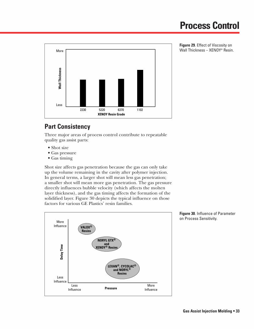
Effect of Viscosity on Wall Thickness . . . . . . . . . . .31Part Consistency . . . . . . . . . . . . . . . . . . . . . . . . . . . . .33Interaction of Wall Thickness
with Gas Penetration . . . . . . . . . . . . . . . . . . . . . . . .34Troubleshooting . . . . . . . . . . . . . . . . . . . . . . . . . . . . . .35
Glossary . . . . . . . . . . . . . . . . . . . . . . . . . . . . . . . . . . . . .36
Literature Available . . . . . . . . . . . . . . . . . . . . . . . . .38
Sales Offices . . . . . . . . . . . . . . . . . . . . . . . . . . . . . . . .39
DISCLAIMER: THE MATERIALS AND PRODUCTS OF THE BUSINESSES MAKING UP THE GE PLASTICS UNIT OF GENERAL ELECTRIC COMPANY, ITSSUBSIDIARIES AND AFFILIATES (”GEP“), ARE SOLD SUBJECT TO GEP‘S STANDARD CONDITIONS OF SALE, WHICH ARE INCLUDED IN THEAPPLICABLE DISTRIBUTOR OR OTHER SALES AGREEMENT, PRINTED ON THE BACK OF ORDER ACKNOWLEDGMENTS AND INVOICES, ANDAVAILABLE UPON REQUEST. ALTHOUGH ANY INFORMATION, RECOMMENDATIONS, OR ADVICE CONTAINED HEREIN IS GIVEN IN GOOD FAITH,GEP MAKES NO WARRANTY OR GUARANTEE, EXPRESS OR IMPLIED, (I) THAT THE RESULTS DESCRIBED HEREIN WILL BE OBTAINED UNDER END-USECONDITIONS, OR (II) AS TO THE EFFECTIVENESS OR SAFETY OF ANY DESIGN INCORPORATING GEP MATERIALS, PRODUCTS, RECOMMENDATIONSOR ADVICE. EXCEPT AS PROVIDED IN GEP‘S STANDARD CONDITIONS OF SALE, GEP AND ITS REPRESENTATIVES SHALL IN NO EVENT BERESPONSIBLE FOR ANY LOSS RESULTING FROM ANY USE OF ITS MATERIALS OR PRODUCTS DESCRIBED HEREIN. Each user bears full responsibilityfor making its own determination as to the suitability of GEP‘s materials, products, recommendations, or advice for its own particular use. Each usermust identify and perform all tests and analyses necessary to assure that its finished parts incorporating GEP materials or products will be safe andsuitable for use under end-use conditions. Nothing in this or any other document, nor any oral recommendation or advice, shall be deemed to alter,vary, supersede, or waive any provision of GEP's Standard Conditions of Sale or this Disclaimer, unless any such modification is specifically agreedto in a writing signed by GEP. No statement contained herein concerning a possible or suggested use of any material, product or design is intended,or should be construed, to grant any license under any patent or other intellectual property right of General Electric Company or any of its subsidiaries or affiliates covering such use or design, or as a recommendation for the use of such material, product or design in the infringementof any patent or other intellectual property right.
27304 Gas Assist Inside.qxd 4/4/00 8:29 AM Page 2
Introduction
Gas Assist Injection Molding • 3
About GEGeneral Electric Company has its roots in the age of inventionwhen, in 1892, it was incorporated as the successor to EdisonElectric founded by pioneering inventor Thomas Edison. Closelyfollowing its founder’s philosophy of innovation and the creativeapplication of technology, GE has grown to become one of thelargest and most diversified companies in the world.
Today, GE products and services make a positive contribution tovirtually every sector of commerce and industry. From jet enginesto financial services, from lighting and medical systems to factoryautomation, power generation, transportation and construction.
About GE PlasticsOf all GE businesses, one of the fastest growing is GE Plastics. In 40 years, GE Plastics has emerged as one of the world’s leadingproducers of engineering thermoplastics. Through applicationdevelopment centers around the world, customers can accessdata from GE designers, engineers, and tooling, processing andfinishing experts, who utilize some of the most sophisticatedequipment and systems available.
Working closely with customers is at the core of the GE Plastics’business culture. Today’s customers need to get the job donebetter, more cost-effectively and within tighter schedules. Havinga concentration of molding equipment, testing laboratories andproduct specialists close to the action permits a cross flow ofinformation that can lead to important breakthroughs andexciting new product developments.
At the nucleus of this unmatched global technical network arethe world-class facilities at GE Plastics’ headquarters in Pittsfield,Massachusetts. Realizing that speed is the key to profitabilitytoday, these services are backed up by production plants in severallocations in the U.S., Europe, Australia, Japan and Mexico.
27304 Gas Assist Inside.qxd 4/4/00 8:29 AM Page 3
4 • Gas Assist Injection Molding
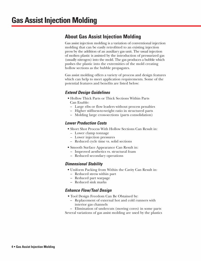
About Gas Assist Injection MoldingGas assist injection molding is a variation of conventional injectionmolding that can be easily retrofitted to an existing injectionpress by the addition of an auxiliary gas unit. The usual injectionof molten plastic is assisted by the introduction of pressurized gas(usually nitrogen) into the mold. The gas produces a bubble whichpushes the plastic into the extremities of the mold creating hollow sections as the bubble propagates.
Gas assist molding offers a variety of process and design featureswhich can help to meet application requirements. Some of thepotential features and benefits are listed below:
Extend Design Guidelines• Hollow Thick Parts or Thick Sections Within Parts
Can Enable:– Large ribs or flow leaders without process penalties– Higher stiffness-to-weight ratio in structured parts– Molding large cross-sections (parts consolidation)
Lower Production Costs• Short Shot Process With Hollow Sections Can Result in:
– Lower clamp tonnage– Lower injection pressures– Reduced cycle time vs. solid sections
• Smooth Surface Appearance Can Result in:– Improved aesthetics vs. structural foam– Reduced secondary operations
Dimensional Stability• Uniform Packing from Within the Cavity Can Result in:
– Reduced stress within part– Reduced part warpage– Reduced sink marks
Enhance Flow/Tool Design• Tool Design Freedom Can Be Obtained by:
– Replacement of external hot and cold runners with interior gas channels
– Elimination of undercuts (moving cores) in some partsSeveral variations of gas assist molding are used by the plastics
Gas Assist Injection Molding
27304 Gas Assist Inside.qxd 4/4/00 8:29 AM Page 4
Introduction
Gas Assist Injection Molding • 5
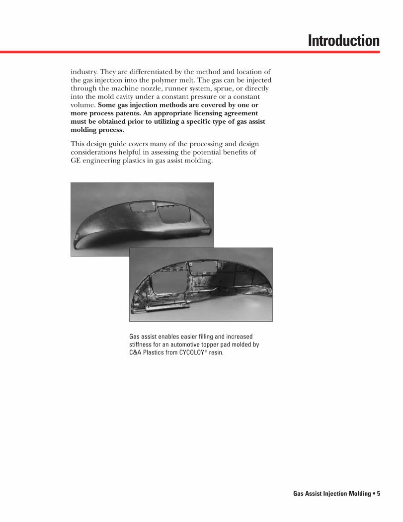
industry. They are differentiated by the method and location ofthe gas injection into the polymer melt. The gas can be injectedthrough the machine nozzle, runner system, sprue, or directlyinto the mold cavity under a constant pressure or a constant volume. Some gas injection methods are covered by one or more process patents. An appropriate licensing agreementmust be obtained prior to utilizing a specific type of gas assistmolding process.
This design guide covers many of the processing and designconsiderations helpful in assessing the potential benefits of GE engineering plastics in gas assist molding.
Gas assist enables easier filling and increased stiffness for an automotive topper pad molded by C&A Plastics from CYCOLOY® resin.
27304 Gas Assist Inside.qxd 4/4/00 8:29 AM Page 5

Process Mechanics
6 • Gas Assist Injection Molding
Stages of Gas Assist MoldingGas assist molding can be divided into three stages: resin injection, primary gas penetration, and secondary gas penetration (See Figure 1).
Stage 1: Resin Injection– The polymer is injected into the mold as a short shot or
partially packed cavity.
Stage 2: Primary Gas Penetration– Gas is introduced into the molten core forming a bubble.
The gas bubble displaces some of the molten core, pushingit into the unfilled cavity and completing the mold filling.
Stage 3: Secondary Gas Penetration– Secondary gas penetration begins at the end of the
filling stage when the polymer has reached the end of the mold. The gas bubble extends as the part cools andthe material shrinks. The extra cavity volume created asthe material shrinks is taken up by the gas bubble. The pressure in the bubble also provides packing of the part during secondary gas penetration.
Figure 1. Stages of Gas AssistMolding. Melt
FrontMelt
(Short Shot)Stage 1
Stage 2
Stage 3
MeltFront
DeformingMelt
Primary Gas Penetration
Hollow Core
MoltenLayer
SolidLayer
Gas Front
Secondary GasPenetration
Path of Least Resistance for Gas PenetrationThe gas bubble propagates within the molten core along the path of least resistance through the cavity. This path isdetermined by lower pressures and higher temperatures. Lower pressure areas are determined by melt front location,cross-sectional area, and position of the polymer injection gate.Higher temperature areas occur in centers of thick sections,high-shear regions, and as a result of mold temperature variations. Higher temperatures also result in lower melt viscosities. During primary gas penetration, the gas bubble
27304 Gas Assist Inside.qxd 4/4/00 8:29 AM Page 6

Process Mechanics
Gas Assist Injection Molding • 7
can only penetrate into areas of the part, where displaced polymer can flow easily to unfilled sections of the mold. Themelt pressure variation within the cavity usually dominates the bubble propagation during primary gas penetration.
Packing Via Gas AssistDuring the packing/hold phase of processing, there will besome additional gas penetration resulting from shrinkage aswell as compression of the molten polymer.
The method of packing by gas assist molding offers some intrinsic advantages over that of injection molding:
• More uniform packing from within the cavity via the gas bubble
• Longer duration of packing (not limited by gate freeze-off)
The pressure during the packing stage in gas assist molding isprovided by the gas bubble and not by the machine screw as intraditional injection molding. The pressure is uniform through-out the gas bubble, and the bubble is distributed throughoutthe cavity. This means that the cavity is maintained at a nearlyuniform pressure during solidification. In traditional injectionmolding, non-uniform stresses result because the pressure cannotbe distributed uniformly throughout the high viscosity resin.This point is illustrated in Figure 2.
Figure 2. Process Physics.
Pres
sure
Flow Length
Nozzle
Injection Molding
Gas Assisted Molding
Pres
sure
Flow Length
Nozzle
Pres
sure
Flow Length
Nozzle
Pres
sure
Flow Length
Nozzle
Packing internally with gas assist also increases the allowableeffective hold time during solidification. Packing via conven-tional techniques is susceptible to gate “freeze-off” while gaspressures may be maintained throughout the cooling time.
27304 Gas Assist Inside.qxd 4/4/00 8:29 AM Page 7
Process Methods
8 • Gas Assist Injection Molding
Process SequenceThe gas assist molding sequence is similar to standard injectionmolding with the addition of the gas injection stages:
1. Mold closes and reaches clamp tonnage.2. Resin is injected into the mold cavity as a short shot or with
reduced packing (no cushion).3. Gas is introduced into the hot melt.4. Gas pressure is maintained during the cooling cycle.5. Gas pressure is released.6. Mold opens and part ejects.
This sequence will not typically add cycle time to the processsince the added steps occur simultaneously during the coolingcycle. Step four replaces, or is coupled with, the packing phaseof standard injection molding.
Gas Injection LocationGas assist methods vary in the location along the melt stream inwhich the gas is introduced. Gas may be introduced to the meltat the machine nozzle, the runner, and/or directly into themold cavity.
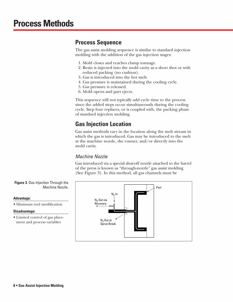
Machine NozzleGas introduced via a special shut-off nozzle attached to the barrelof the press is known as “through-nozzle” gas assist molding(See Figure 3). In this method, all gas channels must be
Figure 3. Gas Injection Through theMachine Nozzle.
N2 Out viaRecovery
N2 In
N2 Out atSprue Break
Part
Advantage:
• Minimum tool modification
Disadvantage:
• Limited control of gas place-ment and process variables
27304 Gas Assist Inside.qxd 4/4/00 8:34 AM Page 8

Process Methods
Gas Assist Injection Molding • 9
connected to the sprue or gate since the gas originates from onepoint. Hot manifold systems are not suggested for this processbecause polymer in the manifold will be displaced by the gas,possibly resulting in inconsistent shot sizes and splay. In somecases, hot manifolds may be eliminated from the tool design by designing flow runners in the part and then hollowing themout to create gas channels. A shut-off portion of the nozzle issuggested to help prevent gas from penetrating into the barrel.
Resin Delivery SystemGas introduced into the runner system or the sprue bushing via gas pins is known as “in-runner” gas assist molding (See Figure 4). If the part is direct-sprue gated, the channels must all originate from the sprue. This method results in hollow runners and/or sprue which can help to reduce the amount ofregrind. Hot manifold systems are not suggested for this processeither, because the polymer will be displaced by the gas in themanifold, possibly resulting in inconsistent shot sizes and splay.A shut-off nozzle is suggested to help prevent gas from penetrat-ing into the machine barrel.
Figure 4. Gas Injection Through theResin Delivery System.
N2 Out at Ejectionor Retraction
Part
N2 In/Out
HydraulicsOptional
Advantage:
• Reduced regrind
Disadvantage:
• Process control
A narrow gas channel is created in a CD tray made from CYCOLAC® resinto improve flatness and dimensional tolerance capacity.
27304 Gas Assist Inside.qxd 4/4/00 8:34 AM Page 9

Process Methods
10 • Gas Assist Injection Molding
Mold Cavity Gas InjectionGas introduced directly into the mold cavity via gas pins is knownas “in-article” gas assist molding (See Figure 5). Parts moldedwith this method can be designed with independent gas channels.Each channel can also have independent gas pressure and timing
Figure 5. Gas Injection Directly intothe Mold Cavity.
N2 Out at Ejectionor Retraction
Part
N2 In/Out
N2 In/Out
HydraulicsOptional
HydraulicsOptional
control. The gas channels do not have to be connected to eachother but will require a gas pin for each channel. The finishedpart will have a hole at each gas nozzle location.
Gas Delivery SystemBecause of its relatively low cost, general availability and inertproperties, nitrogen has become the standard gas used by theplastics industry. The discussion herein pertains exclusively to nitrogen gas.
Gas SupplyNitrogen gas is generally obtained from three methods:
1. Nitrogen bottles2. Evaporated from a liquid nitrogen source3. Membrane filtered from air
Nitrogen bottles are readily available for new gas installations,demonstrations, and small production volumes. Larger produc-tion volumes are best handled by one of the other methods. Theselection of gas production from the other methods is determinedby cost which will vary based on geographical location.
Advantage:
• Puts gas where gas is needed
Disadvantage:
• Extra tool modification toincorporate gas pins
27304 Gas Assist Inside.qxd 4/4/00 8:30 AM Page 10

Process Methods
Gas Assist Injection Molding • 11
Gas HosesSmall diameter gas hoses (0.05”) are generally suggested.Larger diameter hoses can help to increase gas pressure delay tothe cavity and may result in hesitation marks on the part. This is particularly important when using a volume control processsince the volume of the hose can be a significant portion of thetotal volume. Hoses should be rated above the maximum work-ing pressure of the process.
Gas Pin DesignThere are many variations of gas pin design currently used in theplastics industry. Examples of some popular designs include:
• Pop-it style gas pins• Sleeve/ejector style gas pins• Cap screw/bushing style gas pins• Micro vented style gas pins
These pins each have their own advantages and disadvantages.Selection of a gas pin style will depend on each particular appli-cation. Some specific designs are covered by patents. Suppliersshould be contacted for gas pin suggestions.
Pressure Control InjectionSystems that utilize a compressor to generate working pressureand regulators to maintain a given set pressure during gas injectionare known as pressure-control processes. Most systems allow thepressure to be profiled into many pressure stages (See Figure 6).Two stages are usually adequate for most applications since thefilling stage occurs quickly and packing may be maintained atconstant pressure. Most gas equipment systems on the markettoday are pressure-control processed.
Volume Control InjectionA system that utilizes a compressor to generate working pressure,and a cylinder and piston device having a given volume, is knownas a “volume-control” process. This system pre-pressurizes thecylinder prior to gas injection. The gas is pushed out of thecylinder and into the part by the piston during gas injection.The gas pressure supplied to the part is not directly controlledand will vary depending on process variables and part volume.A typical pressure profile is shown in Figure 6.
Advantage:
• Direct process control of pressure
Disadvantage:
• Does not auto-correct gas pins clogs
Advantage:
• Auto-corrects gas pin clogs
Disadvantage:
• Indirect control of pressure
27304 Gas Assist Inside.qxd 4/4/00 8:30 AM Page 11

Process Methods
12 • Gas Assist Injection Molding
This method has the unique feature of automatically un-clogging gas pins. This works because a constant volume of gas is pushed into the hose whether the pin is clogged or open.If the pin is clogged, the small volume of the hose results in alarge pressure spike at the gas pin which acts to clear the clog.
Gas Venting and RecoveryGas in the part should be vented prior to the mold opening.Venting gas at mold opening may result in surface defects abovethe gas channels. The gas can either be vented to atmosphere orrecovered and used again. Gas which is recovered is contaminatedfrom exposure to molten resin. Filtering of the gas is suggestedif it is to be recycled. Venting through mold pins will generallyhasten pin clogging because of this contamination. Retractablemold pins typically offer the best alternative for venting.
Figure 6. Pressure and VolumeControl Profiles.
An automotive door handlemolded at ITW utilizes XENOY®
resin. Gas assist injection molding enables this handle
with thick wall sections to bemolded in short cycle times
while reducing material consumption.
Pressure Control
Volume Control
Time (seconds)
Pres
sure
(psi
)
1000
800
600
400
200
0 10 20 30
27304 Gas Assist Inside.qxd 4/4/00 8:30 AM Page 12

Part Performance
Gas Assist Injection Molding • 13
Structural PerformanceTwo important categories of structural part performance arestiffness and strength. Both are system properties which dependon part geometry, material, loading conditions and constraints.Part stiffness is a measurement of a part’s resistance to deflectionunder an applied load, whereas part strength is a measurementof the load-carrying capability of a part. Through its influenceon part geometry, gas assisted molding affects both part stiffnessand part strength.
Part StiffnessThrough proper design and process control, higher stiffness-to-weight ratios can be obtained with gas assisted moldingthan by conventional means. This benefit is usually much more pronounced for parts in which the gas flows through a contained-channel. For example, hollow tubes created with gasassist molding can have stiffness-to-weight ratios 40% or morehigher than if molded solid. In contrast, parts such as ribbedplates generally have stiffness-to-weight ratios that are typicallyonly 5% higher than their identical solid counterparts.
Figure 7 shows how the stiffness increases with larger ribgeometries designed for gas-assist molding. The figure alsoshows that stiffness can decrease as a result of gas fingering(migration of gas outside its channel). Parts with fingering may still have greater stiffness than traditionally designed parts. Fingering can be minimized with proper design and processing techniques.
Geometry
Stiff
ness
/Fla
t Pla
te S
tiffn
ess
0
5
10
15
20
Fingering
Figure 7. Stiffness of Hollow Ribs.
27304 Gas Assist Inside.qxd 4/4/00 8:30 AM Page 13
Part Performance
14 • Gas Assist Injection Molding
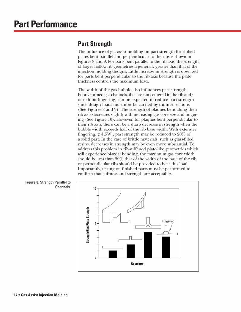
Part StrengthThe influence of gas assist molding on part strength for ribbedplates bent parallel and perpendicular to the ribs is shown inFigures 8 and 9. For parts bent parallel to the rib axis, the strengthof larger hollow rib geometries is generally greater than that of theinjection molding designs. Little increase in strength is observedfor parts bent perpendicular to the rib axis because the platethickness controls the maximum load.
The width of the gas bubble also influences part strength.Poorly formed gas channels, that are not centered in the rib and/or exhibit fingering, can be expected to reduce part strengthsince design loads must now be carried by thinner sections(See Figures 8 and 9). The strength of plaques bent along theirrib axis decreases slightly with increasing gas core size and finger-ing (See Figure 10). However, for plaques bent perpendicular totheir rib axis, there can be a sharp decrease in strength when thebubble width exceeds half of the rib base width. With extensivefingering, (>1.5W), part strength may be reduced to 20% of a solid part. In the case of brittle materials, such as glass-filledresins, decreases in strength may be even more substantial. Toaddress this problem in rib-stiffened plate-like geometries whichwill experience bi-axial bending, the maximum gas core widthshould be less than 50% that of the width of the base of the ribor perpendicular ribs should be provided to bear this load.Importantly, testing on finished parts must be performed toconfirm that stiffness and strength are acceptable.
Figure 8. Strength Parallel toChannels.
Geometry
Stre
ngth
/Fla
t Pla
te S
tren
gth
0
5
10
Fingering
27304 Gas Assist Inside.qxd 4/4/00 8:30 AM Page 14

Part Performance
Gas Assist Injection Molding • 15
Geometry
Stre
ngth
/Fla
t Pla
te S
tren
gth
0.0
1.5
1.0
0.5
2.5
2.0
3.0
Fingering
Figure 9. Strength Perpendicular to Channels.
Figure 10. Influence of Bubble Sizeon Part Strength.
Bubble Width
% S
tren
gth
of S
olid
Sec
tion
0
60
40
20
100
80
120
W
W
FingeredContained
Parallel to Channel
Perpendicular to Channel
0W 2W1W
27304 Gas Assist Inside.qxd 4/4/00 8:30 AM Page 15

Arm Rests, Handles
Part Design
16 • Gas Assist Injection Molding
Types of PartsMost gas assist molded parts may be categorized into two types:
• Contained-channel: Tubes• Open-channel: Panels
Some parts may be a combination of these two types:
Figure 11. Contained-Channel Parts.
Open-Channel Parts: PanelsExamples of open-channel parts are access covers, panels, shelvesand chassis. These parts consist of a nominal thin wall with gaschannels traversing the part similar to traditional ribs. Figure 12illustrates an open channel gas assist part. These parts are moredifficult to design and process because the gas may migrate intothe thin-walled regions of the part. This is known as fingering.
Contained-Channel Parts: TubesExamples of contained-channel parts are tubes, arm rests, handlesand frames. These parts consist merely of a single thick sectionor channel through which the gas must penetrate. Figure 11illustrates a cross section of acontained-channel part used as a structural frame. Theseparts are generally easier toprocess because the gas has aclearly defined path throughwhich to propagate with no thin-walled areas which mustremain gas free.
27304 Gas Assist Inside.qxd 4/4/00 8:30 AM Page 16

Part Design
Gas Assist Injection Molding • 17
Gas Channel LayoutThe layout of gas channels within a cavity involves defining locations for the gas channels and gas nozzle relative to the sprueor gates. This procedure is particularly important for engineeringthermoplastic resins such as those sold by GE Plastics. With thesehigh performance resins, shrinkages are typically low. This meansthat primary gas penetration (determined by design) is dominantover the secondary gas penetration (determined by shrinkage).
StrategyIn general, the main design objective is to set-up a filling patternwithin the cavity in which the lowest pressure exists near the endof each channel after the plastic is delivered. This helps to definethe path of least resistance along the gas channels. One way ofpromoting this condition is to position the channels in such a waythat they end near the last areas of the cavity to fill (See Figure 13).
Figure 12. Open-Channel Parts.
Shelves, Chassis, Covers
Design of Open Channel PartsThe three main objectives when designing a part for gas assistmolding are to:
• Obtain the best layout of gas channels throughout the part• Balance the polymer fill through the part• Size the channels properly with respect to the part
Parts designed with these objectives, and the suggestions in thissection in mind, are more likely to yield well-filled and well-cored-out parts.
Gas assist molding of large parts, such as this auto bumper beam, enable evaluation of parts with a high degree of structure while retaining surface aesthetics.
27304 Gas Assist Inside.qxd 4/4/00 8:30 AM Page 17

Part Design
18 • Gas Assist Injection Molding
The challenge in accomplishing this objective is that the additionof channels into the cavity will typically disrupt the filling patternand affect the location of the last area to fill (See Gas ChannelSize and Geometry on page 22).
Figure 13. Layout Strategy.
”Manifold“ Design
”Radial“ Design
”Edge“ Channels
Gas Pin
Gas Pin
Gas Pin
Gas Pin
Center Gate
Center Gate
Local InjectionGas pin
Gas pin
Gate
Gate
Parts with Large Areas of Thin WallMost parts which have large thin-walled regions should have the polymer gated directly into the thin wall (See Figure 14).This will help reduce the flow-leader effect of the gas channels,promoting filling of the thin-walled areas and help keep the last area to fill near the end of the channel. In this case, someadditional packing from the screw may be used since the gas is not fully distributed throughout the part.
Figure 14. Parts with Large Areasof Thin Wall. Last Area
To Fill
Resin In
Gas In
27304 Gas Assist Inside.qxd 4/4/00 8:32 AM Page 18

Part Design
Gas Assist Injection Molding • 19
Channel OrientationThe channels should also be oriented in the direction of themelt flow. “Zigzagging” of a channel usually does not enhanceflow in the part and may lead to fingering (See Figure 15).
Figure 15. Improper ChannelOrientation Relative to Gate.
GasFingering
Gas In
Polymer Gate
Last Pointto Fill
In cases such as these, the path of least resistance is determinedby the pressure within the cavity. The gas bubble may circum-vent the channel and flow to the low pressure (last area to fill)region through the thin wall.
The fascia for a drive-up automatic teller machine,molded by Sajar Plastics, Inc.from CYCOLOY ABS/PC resin,uses the gas assist process to achieve light weight, dimensional stability and structural rigidity.
27304 Gas Assist Inside.qxd 4/4/00 8:32 AM Page 19

Part Design
20 • Gas Assist Injection Molding
Closed LoopsClosed loops are sometimes found to be acceptable if the chan-nels are small or are in corners. Closed-loop channels shouldbe avoided if complete coring is required (See Figure 16). Closed loops can result in solid channels where the two gas bubbles converge.
Figure 16. Gas Penetration with Closed Loop Channels.
Part
Part
Flow Around CornersGas traveling through a curved channel tends to follow theshortest path through the curve. This means the bubble maycut to the inside of sharp corners and create an uneven thicknessdistribution (See Figure 17). To help avoid thin inside corners,a generous radius on gas assist channels can be used.
ThinWall
Avoid Sharp Corners Generous Radius Can CreateBetter Thickness Distribution
Figure 17. Flow Around Corners.
27304 Gas Assist Inside.qxd 4/4/00 8:32 AM Page 20

Part Design
Gas Assist Injection Molding • 21
Balancing of Polymer FillDuring primary gas penetration, the gas bubble must displace thepolymer within the gas channels to an unfilled area in the cavity.Therefore, for parts with multiple or branched gas channels, it is necessary to balance the filling of the gas channels. If somegas channels fill sooner than others, poor gas penetration inthese channels can result. One way to help balance filling is by sizing the gas channels relative to one another. For example,gas channels near the gate would be smaller since they wouldordinarily fill first, and gas channels farthest from the gatewould be the largest in order to increase flow and balance filling (See Figure 18).
The balancing of fill through channel sizing may be only partiallyeffective. In some cases, multiple polymer gates can be added tohelp balance the flow.
Mold filling analysis can be beneficial in assessing the fillingpatterns. The gas channel sizes may then be adjusted to furtherbalance the flow analytically before the tool is cut.
Figure 18. Balancing Polymer Fillwith Channel Size.
Melt Front
UnbalancedMultiple Gas Channels
UnbalancedMultiple Gas Channels
Properly BalancedMultiple Gas Channels
Center GateCenter Gate
Automotive headlamp reflectorswere previously molded in bulkmolding compound molds with thick wall sections. Using gasassist, ULTEM® 1000 resin and thesame molds, the molder was ableto hollow out the thick areas.
27304 Gas Assist Inside.qxd 4/4/00 8:32 AM Page 21

Part Design
22 • Gas Assist Injection Molding
Gas Channel Size and GeometryGas channel size can vary significantly with part design. A 2:1 ratioof channel dimension to nominal wall is typically used as a startingpoint for channel size (See Figure 19). There is no lower bound,however, consistent gas penetration requires some definition ofbubble propagation by means of a gas channel. Thin parts moldedusing the “full shot” technique may have little or no gas channel.The upper bound depends on the geometry of the part and theposition of the channel within the part. Large channels can pre-sent a problem in that the polymer may “race track” throughthem, leaving the adjacent thin-walled areas unfilled.
Figure 19. Typical Gas ChannelGeometries.
ba
ba
ba
ba
ba
ba
ba ≈ 2
One approach is to start with channels which are relatively smallto minimize this effect. These channels can still offer most of the benefits of gas assist molding. Parts which require greaterstrength or rigidity can be designed by adding ribs. A rib is moreefficient than gas channels for adding structure to the part andwill not contribute to the flow-leader effect the way large channelswill. A rib and channel may be combined to yield the benefits of both. Ribs on top of gas channels generally add greater benefitthan traditional ribs, since their thickness can be a full 100%that of the nominal wall. (The thickness of traditional ribs without a channel are generally only 60% that of the nominalwall.) Figure 19 depicts some typical gas channel geometries.
Channel System Design ProcedureThe design procedures for gas assist molding previously discussedare summarized in Table 1. These procedures are provided merelyas a guideline. Each part presents unique issues which must bedealt with on an individual basis. There is no substitute for end-use testing of finished parts.
27304 Gas Assist Inside.qxd 4/4/00 8:32 AM Page 22

Part Design
Gas Assist Injection Molding • 23
Table 1. Gas Assist Injection Molding Development Process.
The Development ProcessWhile the process is open to innovation, a systematic approach may provide a more reliable path from a concept to a production part, as illustrated below.
*GE Plastics Customer Support: Contact your local GE Plastics’ sales office or Commercial Development Center listed on the back cover of this publication or call: (800) 845-0600 for technical inquiries or requests for literature.
Present the Challenge
ChooseMaterial
Gas ChannelLayout
Select GateLocation
Mold FillingAnalysis
RefineLayout
AdjustChannel Size
ReconsiderGating
BalancedFilling
FinalDesign
Go toTooling
“Why use gas assistedmolding?” Determinethe benefits of using this process
Select material basedon part requirements.Any injection moldinggrade of material may begas assisted molded.
GE Plastics Support*Application DevelopmentEngineeringSales/Marketing
Sketch out part andchannel locationsbased on design rules.
Based on balancedfilling of the part.
GE Plastics Support*Application DevelopmentEngineeringComputer AidedEngineering
Start with uniform sizebased on design rules.
Adjust channel Size: Goal is to balance the fillpattern.
Refine Layout:Consider difficultareas to fill. Addflow leaders.
Reconsider Gating:Gating method canassist in balancingfilling. Goal is tobalance fill pattern
NO
YES
GE Plastics Support*Application DevelopmentEngineeringComputer AidedEngineering
GE Plastics Support*Application DevelopmentEngineeringComputer AidedEngineering
27304 Gas Assist Inside.qxd 4/4/00 8:32 AM Page 23

Part Design
24 • Gas Assist Injection Molding
Process AnalysisMold filling analysis can be used effectively to help design partsfor gas assist molding. In addition to the traditional filling software,some suppliers offer software that simulates the gas injectionphase of the process. It is suggested that this software be testedfor accuracy before general use. Particular attention should be paid to both stages of gas penetration. (See Stages of GasAssist Molding on page 6.) Most traditional filling software hasthe ability to predict the overall filling pattern, the last areas offill, weld line locations and air entrapment. This information, coupled with the channel design procedure outlined previously,can greatly reduce the time and cost of tooling iterations toachieve a balanced fill.
The main concern for process simulation is how to model the gaschannel. These gas channels may be relatively thick as comparedto the nominal wall thickness. The channels’ aspect ratio willdetermine whether to use thin-shell elements or runner elements.Thin-shell elements are generally suggested when the gas channelhas a width that is greater than four times that of its thickness.Runner elements are usually suggested when the gas channelhas a width that is less than four times that of the thickness. Thefilling pattern plot at 85 to 98% fill is typically used to evaluatethe filling of the part. Modification can then be made to balancethe filling pattern. (See “Balancing of Polymer Fill” on page 21).
Part AnalysisBefore the structural performance of gas assisted molded partscan be evaluated, the wall thickness surrounding the hollow coremust be determined. This can be accomplished either by physicalmeasurements of the part or analytical predictions. Commercialsoftware is available to predict gas coring and penetrations, butits accuracy should be considered. If no accurate means of assess-ing the gas channel wall thickness exists, then a good starting pointmay be to use a wall thickness equal to 1/3 of the effective channelradius. Once the size and the shape of the hollow core have beendetermined, the part’s structural performance can be assessed.
For complex part geometries and loading conditions, finite elementanalyses are needed to help predict structural performance. Bothhollow-beam elements and shell elements could be used to modelthe channel. The choice of element depends upon the time avail-able, the accuracy required, and the part geometry.
27304 Gas Assist Inside.qxd 4/4/00 8:32 AM Page 24

Part Design
Gas Assist Injection Molding • 25
For contained-channel parts, the choice between a shell elementor beam element isn’t as critical because both perform similarly.The primary difference is that shell elements can model channelcollapse, but beam elements cannot.
For open-channel parts, the element choice for modeling thegas channel is more important than it is for contained-channels.In general, beam elements require less modeling time, but pro-vide less accurate bending results than shell elements. The beamelement predictions can often be improved by shifting the beamaxis to its neutral plane with respect to the plate. Some commonchannel cross sections and their shell representations are shownin Figure 20.
Shell Elements
Shell Elements
Shell Elements
Figure 20. Common ChannelModels.
When the gas channel dimensions are known and the gas channelsare properly modeled using shell elements, more accurate stiff-ness and strength predictions can usually be obtained. As anexample, consider the bending of a plate with a triangular gaschannel rib. The finite element load-displacement response andthe experimental load-displacement response of this ribbed plateare shown in Figure 21. The predicted stiffness and strength ofthe part are very close to its actual stiffness and strength.
27304 Gas Assist Inside.qxd 4/4/00 8:32 AM Page 25

Part Design
26 • Gas Assist Injection Molding
Material SelectionAll resins currently available in the GE Plastics’ injection moldinggrades portfolio have been molded successfully with the gas assistprocess. Material selection should be made on the basis of theusual performance factors such as: stiffness, strength, chemicalresistance and flame retardance.
Secondary OperationsMost secondary operations for gas assist molded parts are thesame as for injection molded parts. One exception is the treat-ment of the hole remaining where gas has entered the part. For certain operations, such as plating, it may be necessary toseal or plug this hole. In this case a staking operation is oftenused. The material required to stake the hole may be includedas integral to the design of the part.
Finite Element PredictionTest Results
Displacement (mm)
Load
(N)
2000
1500
1000
500
00 5 10
Figure 21. Displacement Response Curves.
For a computer bezel, gas assist
molding allows heavy bosses to be located
behind the thin aesthetic wall
without sink.
27304 Gas Assist Inside.qxd 4/4/00 8:32 AM Page 26

Tool Design
Gas Assist Injection Molding • 27
Mold MaterialsGas assist molding is a process similar to traditional injectionmolding. For this reason, tool design is similar. Additional information is presented in GE Plastics’ publication PBG-135.
• Prototype and low-volume applications– Kirksite*– Cast aluminum– Machined aluminum– Epoxy
• Medium-volume applications– Machined aluminum– Machined tool steel
• High-volume applications– Machined tool steel
*Trademark of NL Industries
GatesResin gates vary with the type of application. Ordinary injectionmolding rules should be followed (see the GE Plastics’ injectionmolding guide for the specific resin being molded).
With in-runner and through-nozzle techniques, gate size mustbe large enough to prevent gate freeze-off before gas injection.This is particularly important for sub or tunnel gates which aregenerally larger than their injection molding counterparts. Also,edge or fan style gates should integrate a gas channel so thatthe gas has a clear path into the cavity.
Cold RunnersOrdinary injection molding rules should be followed. Size andshape should be adequate to deliver the given volume of polymerto the part resulting in the desired filling pattern. With through-nozzle or in-runner system techniques, the runner system willbe hollow.
27304 Gas Assist Inside.qxd 4/4/00 8:32 AM Page 27

Tool Design
28 • Gas Assist Injection Molding
Hot Manifold SystemsHot manifolds can be used with in-article gas assist molding. A valve gate manifold system may be required, depending ongas channel location. If the gas finds its way to the hot manifoldsystem, it can enter the manifold and push or compress the hot resin back into the machine barrel. This is likely to resultin inconsistent shot sizes and increased rejects. Hot manifoldsare not suggested with through-nozzle gas assist techniques.
VentingStandard injection molding venting is suggested. Vents shouldbe assessed during tool development. No special rules apply inmost situations.
CoolingMold temperature can affect the wall thickness in the gas channel.Use the standard mold temperatures suggested for the material.No special consideration is required in most situations.
ShrinkageThe gas assist process generally produces parts with overallshrinkages similar to injection molding. Refer to the appropriateinjection molding guide for the specific GE resin material being molded.
Gas Pin LocationWith in-article and in-runner systems, the gas pin location is acritical tool-design function. Polymer must cover the gas nozzleprior to gas introduction. Consideration of part design and fillingpattern must be given when determining nozzle location. Referto the Part Design section of this guide on pages 16-26 for addi-tional information on the subject.
Shut-off NozzlesShut-off nozzles are suggested when using in-article or in-runnertechniques (without valve gates). They will help prevent gas fromentering the runner and pushing the material backward. Addinghold pressure can be used instead of a shut-off nozzle in somecases. The proximity of the gas channel to the polymer gateshould determine the amount of hold pressure.
Caution should be used when selecting a shut-off nozzle for shearsensitive material. Flow around these nozzles can induce splay insome cases.
27304 Gas Assist Inside.qxd 4/4/00 8:32 AM Page 28
Process Control
Gas Assist Injection Molding • 29
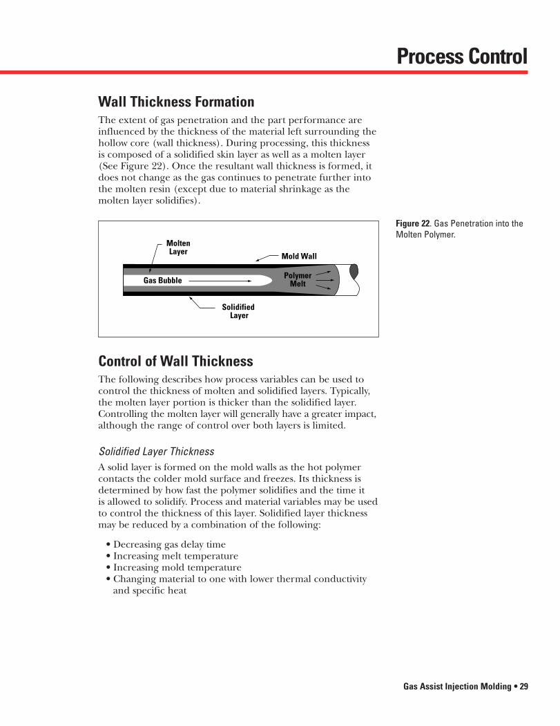
Wall Thickness FormationThe extent of gas penetration and the part performance areinfluenced by the thickness of the material left surrounding thehollow core (wall thickness). During processing, this thickness is composed of a solidified skin layer as well as a molten layer(See Figure 22). Once the resultant wall thickness is formed, itdoes not change as the gas continues to penetrate further intothe molten resin (except due to material shrinkage as themolten layer solidifies).
Figure 22. Gas Penetration into theMolten Polymer.
Gas Bubble PolymerMelt
Mold Wall
MoltenLayer
Solidified Layer
Control of Wall ThicknessThe following describes how process variables can be used tocontrol the thickness of molten and solidified layers. Typically,the molten layer portion is thicker than the solidified layer.Controlling the molten layer will generally have a greater impact,although the range of control over both layers is limited.
Solidified Layer ThicknessA solid layer is formed on the mold walls as the hot polymercontacts the colder mold surface and freezes. Its thickness isdetermined by how fast the polymer solidifies and the time it is allowed to solidify. Process and material variables may be usedto control the thickness of this layer. Solidified layer thicknessmay be reduced by a combination of the following:
• Decreasing gas delay time• Increasing melt temperature• Increasing mold temperature• Changing material to one with lower thermal conductivity
and specific heat
27304 Gas Assist Inside.qxd 4/4/00 8:32 AM Page 29

Process Control
30 • Gas Assist Injection Molding
Molten Layer ThicknessAs the solid layer forms, gas is injected through the polymer melt,displacing the polymer throughout the mold. The advancing gasbubble leaves a layer of molten resin (in addition to the solidlayer) surrounding the hollow core.
The thickness of the molten layer between the solid layer and thegas core is determined by the velocity of the gas bubble throughthe molten core and the rheological properties of the resin.Faster bubble velocities usually result in a thinner molten layeruntil a limit is reached (See Figure 23.) The bubble velocity isdetermined by the gas pressure, polymer viscosity and distanceto melt front.
Figure 23. Molten Layer Thickness.0.40
0.35
0.30
0.25
0.20
0.15
0.10
0.05
0.00
Thic
knes
s Ra
tio (t
/R)
Bubble Velocity
Range For Primary Gas Penetration
Range For Secondary Gas Penetration
TypicalEngineering
Thermoplastic
Newtonian Melt
0
R
t
It is difficult to maintain a constant gas bubble velocity throughoutthe gas injection phase because the distance between the gasfront and the melt front is continuously decreasing. This reducesthe resistance to flow and increases the velocity of the gas.Molten layer thickness can often be reduced by a combinationof the following:
• Increasing the gas pressure (See Figure 23)• Increasing the melt temperature• Decreasing the initial shot size• Changing to a material with lower viscosity or more
shear thinning
27304 Gas Assist Inside.qxd 4/4/00 8:33 AM Page 30

Process Control
Effect of Gas PressureThe gas pressure used during the primary gas filling phase willhave a direct impact on the bubble velocity. Increasing bubblevelocity results in thinner wall channels (See Figure 23). The gaspressure achieved within the cavity is strongly dependent on theorifice size in the gas pin used. Gas control systems do notreport the actual pressure reliably because of the pressure dropacross the gas pin. Gas pressures after completing fill should beadjusted to control sink marks and fingering.
Effect of Viscosity on Wall ThicknessAs the polymer viscosity increases, the gas channel wall thicknesswill increase. Polymer viscosity can be varied by changing thematerial or melt temperature. As the melt temperature increases,the viscosity decreases, decreasing the wall thickness. Materialclogs, from LEXAN® 121 resin to LEXAN 141 resin, forinstance, can increase viscosity and wall thickness.
One exception to this effect is materials which have fillers such asglass fibers. In these materials, the fillers cause the material toshear closer to the surface as the bubble propagates resulting inthinner walls.
Figures 24 through 29 show the effect of viscosity on wall thicknessfor various grades within a product family. Each resin is examinedat its upper processing limit.
Figure 24. Effect of Viscosity onWall Thickness – CYCOLAC® Resin.
Figure 25. Effect of Viscosity onWall Thickness – CYCOLOY® Resin.
GPM6300CYCOLAC Resin Grade
BDT6500 GPM5600 GHT4400 GPM4700
Wal
l Thi
ckne
ss
More
Less
CYCOLOY Resin GradeC2800 C1110 C2950 C1950
Wal
l Thi
ckne
ss
More
Less
Gas Assist Injection Molding • 31
27304 Gas Assist Inside.qxd 4/4/00 8:33 AM Page 31

Process Control
32 • Gas Assist Injection Molding
Figure 26. Effect of Viscosity onWall Thickness – LEXAN® Resin.
Figure 27. Effect of Viscosity onWall Thickness – NORYL® Resin.
Figure 28. Effect of Viscosity onWall Thickness – VALOX® Resin.
Wal
l Thi
ckne
ss
More
LessCQ1010L
LEXAN Resin Grade101/201 141/241 121/221 151
N225XNORYL Resin Grade
731 N190X GTX902 PX1265
Wal
l Thi
ckne
ss
More
Less
735VALOX Resin Grade420 325 830
Wal
l Thi
ckne
ss
More
Less
27304 Gas Assist Inside.qxd 4/4/00 8:33 AM Page 32
Process Control
Gas Assist Injection Molding • 33
Part ConsistencyThree major areas of process control contribute to repeatablequality gas assist parts:
• Shot size• Gas pressure• Gas timing
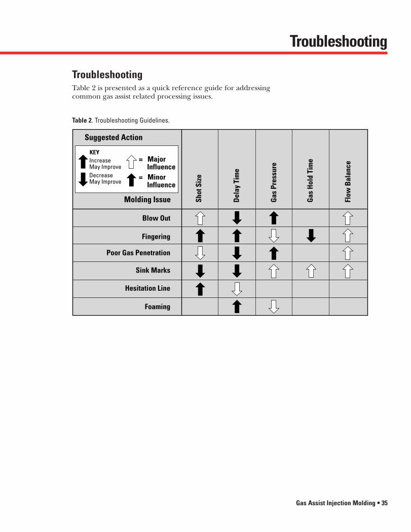
Shot size affects gas penetration because the gas can only takeup the volume remaining in the cavity after polymer injection.In general terms, a larger shot will mean less gas penetration; a smaller shot will mean more gas penetration. The gas pressuredirectly influences bubble velocity (which affects the moltenlayer thickness), and the gas timing affects the formation of thesolidified layer. Figure 30 depicts the typical influence on thosefactors for various GE Plastics’ resin families.
Figure 29. Effect of Viscosity onWall Thickness – XENOY® Resin.
2230XENOY Resin Grade5220 6370 1102
Wal
l Thi
ckne
ss
More
Less
Figure 30. Influence of Parameteron Process Sensitivity.
Pressure
Del
ay T
ime
MoreInfluence
LessInfluence
LessInfluence
MoreInfluence
LEXAN®, CYCOLAC®
and NORYL®
Resins
NORYL GTX®
andXENOY® Resins
VALOX®
Resins
27304 Gas Assist Inside.qxd 4/4/00 8:33 AM Page 33

Process Control
34 • Gas Assist Injection Molding
Interaction of Wall Thickness with Gas PenetrationProcess changes which affect channel wall thickness will resultin a corresponding change in gas penetration (for constantshot size). Shot size must be adjusted along with changes toother process variables to counteract this effect. The interactionbetween these variables is shown in Figure 31.
Figure 31. Wall Thickness vs. GasPenetration and Shot Size. Resultant Penetration for
Variation in Wall Thickness(Same Shot Size)
Incr
easi
ng W
all T
hick
ness
Incr
easi
ng S
hot S
ize
Resultant Penetrations forVariation in Shot Size(Same Wall Thickness)
Penetration Penetration
GOAL: Minimize Shot Size and Minimize Wall Thickness.
Gas channels assist the flow of CYCOLOY ABS/PC resin
providing added dimensionalstability to thick and thin
sections of this mail sortingmachine shelf molded by
Sajar Plastics, Inc.
27304 Gas Assist Inside.qxd 4/4/00 8:33 AM Page 34
Troubleshooting
Gas Assist Injection Molding • 35
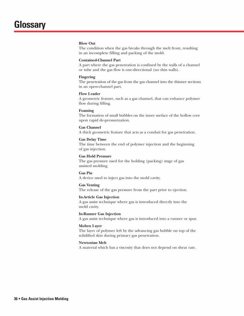
TroubleshootingTable 2 is presented as a quick reference guide for addressingcommon gas assist related processing issues.
Table 2. Troubleshooting Guidelines.
Suggested Action
Blow Out
Shot
Siz
e
Gas
Pre
ssur
e
Del
ay T
ime
Gas
Hol
d Ti
me
Flow
Bal
ance
Fingering
Poor Gas Penetration
Sink Marks
Hesitation Line
Foaming
Molding Issue
Increase May ImproveDecrease May Improve
KEY
= Minor Influence
= Major Influence
27304 Gas Assist Inside.qxd 4/4/00 8:33 AM Page 35
36 • Gas Assist Injection Molding
Blow OutThe condition when the gas breaks through the melt front, resultingin an incomplete filling and packing of the mold.
Contained-Channel PartA part where the gas penetration is confined by the walls of a channelor tube and the gas flow is one-directional (no thin walls).
FingeringThe penetration of the gas from the gas channel into the thinner sectionsin an open-channel part.
Flow LeaderA geometric feature, such as a gas channel, that can enhance polymerflow during filling.
FoamingThe formation of small bubbles on the inner surface of the hollow coreupon rapid de-pressurization.
Gas ChannelA thick geometric feature that acts as a conduit for gas penetration.
Gas Delay TimeThe time between the end of polymer injection and the beginning of gas injection.
Gas Hold PressureThe gas pressure used for the holding (packing) stage of gas assisted molding.
Gas PinA device used to inject gas into the mold cavity.
Gas VentingThe release of the gas pressure from the part prior to ejection.
In-Article Gas InjectionA gas assist technique where gas is introduced directly into the mold cavity.
In-Runner Gas InjectionA gas assist technique where gas is introduced into a runner or spur.
Molten LayerThe layer of polymer left by the advancing gas bubble on top of thesolidified skin during primary gas penetration.
Newtonian MeltA material which has a viscosity that does not depend on shear rate.
Glossary
27304 Gas Assist Inside.qxd 4/4/00 8:33 AM Page 36
Glossary
Gas Assist Injection Molding • 37
Open-Channel PartA part where gas penetration occurs in a rib or thicker section but isopen to penetrate into the thin-wall areas.
Path of Least ResistanceThe flow direction of the gas governed by regions of highest melt andlowest pressure.
Pressure Controlled ProcessThe process in which the melt is displaced by the gas delivered undercontrolled pressure.
Primary Gas PenetrationThis occurs when the gas pushes the polymer into the extremities ofthe mold while hollowing out thicker sections of the cavity.
Secondary Gas PenetrationAdditional gas penetration due to the shrinkage of the cooling polymer.
Short ShotThe molten polymer that is less than the cavity volume, which is injectedinto the mold prior to gas injection.
Shut-Off NozzleAn injection molding nozzle which allows flow in only one direction.
Solidified LayerThe thin layer of solid polymer in contact with the mold surface during molding.
Through-Nozzle Gas InjectionA gas assist technique where gas is introduced via a special nozzleattached to the barrel of the press.
ViscosityThe material property which measures resistance to flow.
Volume Controlled ProcessThe process in which a fixed volume of gas is injected into the part.The gas pressure is not directly controlled.
27304 Gas Assist Inside.qxd 4/4/00 8:33 AM Page 37

38 • Gas Assist Injection Molding
Literature
® CYCOLAC, CYCOLOY, LEXAN, NORYL, NORYL GTX, ULTEM, VALOX, and XENOY are Registered Trademarks of General Electric Company.
™ The Weatherables and GE Select are Trademarks of General Electric Company.
A comprehensive 380-page guidethat provides in-depth informationto assist engineers design state-of-the-art equipment and componentswith GE engineering thermoplastics.Includes explanations of productgroupings and grades, applicationdevelopment assistance, proceduresand data relating to material selec-tion, design assistance, prototypingand processing considerations,assembly and finishing details. Alsoincluded is a glossary of commonlyused engineering terms that relateto plastics.
Complete access to over 3,000 pages of technical information isavailable on-line on the Internet.Users can navigate within GE Plastics’ www.geplastics.comaddress to access the literaturedescribed above as well as GE Select™, an engineering data-base containing product datasheets for over 500 grades of GE engineering resins.
We’re pleased to offer our customersan extensive library of product,processing, technical and generalliterature. From our popular DesignGuide to our in-depth Product andProcessing Guides, our literature isdesigned to act as a critical referencetool for our full product portfolio.To order a particular guide or aseries of multiple guides, please call1-800-845-0600 or access our on-line order center at www.geplastics.
A broad range of valuable infor-mation can be found in a host ofgeneral literature from GE Plastics.From our Global Resources and Six Sigma Quality brochures, to The Weatherables™ and new PolymerProcessing Development Centerbrochures, we offer you in-depthcoverage of our key business andtechnological initiatives.
A series of brochures containinginformation to assist designers and processors understand thecharacteristics of various polymerchemistries within GE Plastics’resin families. Includes informationto help select engineering thermo-plastics for specific applications.
Over 200 pages of informationcontained in 17 brochures to assistprocessors fabricating componentsusing injection molding processes.Includes general information onconverting engineering thermo-plastics together with specific processing details and moldingparameters for each GE resin familyand grade. Additional processingpublications containing informationon Thinwall,SM Gas Assist, Thermo-forming and Engineering StructuralFoam processing techniques arealso available.
Key product family products, markets and services are featured in a variety ofnew product-line brochures. Includes property and application informationon our Crystalline, Engineered Styrenics Resins, LEXAN®, ULTEM® andNORYL® product lines.
Provides comprehensive propertyprofiles and descriptive informa-tion on GE Plastics’ entire productportfolio with data on testing methods utilized to evaluate engi-neering materials.
General Guides
Design Guide
Product Guides
Processing Guides
GE Product Families
The Internet
27304 Gas Assist Inside.qxd 4/4/00 8:33 AM Page 38

AMERICASUnited States
GE PlasticsOne Plastics AvenuePittsfield, MA 01201 USATelephone: (413) 448-7110Cable: GEPLASTICS
California★ Western Business Region
4160 Hacienda DrivePleasanton, CA 94588Telephone: (510) 734-0161
Georgia★ Commercial Development Center
205 Scientific DriveNorcross, GA 30092Telephone: (770) 662-1000
IllinoisSuite 100, One Corporate Lakes2525 Cabot Drive, Lisle, IL 60532Telephone: (630) 505-2500
Massachusetts★ One Plastics Avenue
Pittsfield, MA 01201Telephone: (413) 448-7110
MichiganP.O. Box 5011Southfield, MI 48086-5011
★ 25900 Telegraph RoadSouthfield, MI 48034Telephone: (248) 351-8000
OhioSuite 660, 6000 Lombardo CenterSeven Hills, OH 44131Telephone: (216) 524-2855
TexasSuite 930, 5430 LBJ FreewayDallas, TX 75240Telephone: (972) 458-0600
Puerto RicoGeneral Computer BuildingP.O. Box 2010 Bayamon Puerto Rico 00960Road 174, No. 101Minillas Industrial Park Bayamon Puerto Rico 00959Telephone: (787) 288-2340Telefax: (787) 288-2348
BrazilGE Plastics South America S/AAv. das Nacoes Unidas, 12995 -20 andarBrooklin Novo04578-000 São Paulo, SP BrazilTelephone: (55) 11-5508-0500Telefax: (55) 11-5505-1757
CanadaGE Plastics – CanadaGeneral Electric Canada Inc.2300 Meadowvale Blvd.Mississauga, OntarioL5N 5P9 CanadaTelephone: (905) 858-5700Telefax: (905) 858-5798
MexicoGE Plastics Mexico S.A. de C.V.Av. Prolongación Reforma #490
4o. PisoColonia Santa Fe01210 Mexico, D.F.Telephone: (525) 257-6060Telefax: (525) 257-6070
EUROPEEuropean Headquarters★ General Electric Plastics B.V.
Plasticslaan 1 4612 PX Bergen op ZoomThe NetherlandsTelephone: (31) 164-292911Telefax: (31) 164-292940General Electric Plastics B.V.P.O. Box 1174600 AC Bergen op ZoomThe NetherlandsTelephone: (31) 164-292911Telefax: (31) 164-291725
AustriaGE Plastics AustriaPottendorfarstrasse 47A-2700 Wiener Neustadt, AustriaTelephone: (43) 2622-39070Telefax: (43) 2622-39047
France★ General Electric Plastics France
S.a.r.L.Z. I. de St. GuénaultBoite Postale No. 67F-91002 Evry/Cedex, FranceTelephone: (33) 1-60796900Telefax: (33) 1-60796922
Germany★ General Electric Plastics GmbH
Eisenstraße 565428 RüsselsheimPostfach 1364-65402 Rüsselsheim, GermanyTelephone: (49) 6142-6010Telefax: (49) 6142-65746
India★ GE Plastics India Limited
405-B, Sector 20Udyog Vihar Phase IIIGurgaon 122016 (Haryana)Telephone: (91) 124-341-801Telefax: (91) 124-341-817
Italy★ GE Plastics Italia S.p.A.
Viale Brianza 18120092 Cinisello BalsamoMilano, ItalyTelephone: (39) 2-61834-301Telefax: (39) 2-61834-305
Spain★ GE Plastics Iberica, S.A.
Avinguda Diagonal 652-65608034 Barcelona, Spain Telephone: (34) 93-252-1606Telefax: (34) 93-280-2619
United Kingdom★ GE Plastics Ltd.
Old Hall RoadSale, Cheshire M33 2HGUnited KingdomTelephone: (44) 161-905-5000Telefax: (44) 161-905-5106
PACIFICPacific Headquarters
GE Plastics Pacific Pte. Ltd.#09-00 GE Tower240 Tanjong Pagar RoadSingapore 0208Telephone: (65) 220-7022Telefax: (65) 326-3290
Australia★ GE Plastics (Australia) Pty. Ltd.
175 Hammond RoadDandenong, Victoria 3175AustraliaTelephone: (61) 3-9703-7200Telefax: (61) 3-9794-8563GE Plastics (Australia) Pty. Ltd.57/2 O’Connell StreetParramatta, New South Wales 2150AustraliaTelephone: (61) 2-9689-3888Telefax: (61) 2-9689-3530GE Plastics (Australia) Pty. Ltd.Legal and General Building206 Greenhill RoadEastwood, South Australia 5063AustraliaTelephone: (61) 8-8272-5044Telefax: (61) 8-8272-2479
ChinaGE Plastics – BeijingGeneral Electric (USA) China
Company, Ltd.3rd Floor, CITIC Building No. 19 Jian Guo Men Wai Ave.Beijing 100004, P.R. ChinaTelephone: (86) 10-6500-6438Telefax: (86) 10-6500-7476
GE Plastics – ShanghaiGE China Company9th Floor, Shartex Center88 Zunyi Road (S)Shanghai 200335, P.R. ChinaTelephone: (86) 21-6270-9623Telefax: (86) 21-6270-9973
Hong KongGE Plastics Hong Kong LimitedRoom 1008, Tower I, The Gateway25 Canton Road, TsimshatsuiKowloon, Hong KongTelephone: (853) 2629-0853Telefax: (853) 2629-0804
IndonesiaGE Plastics – IndonesiaKH Mas Mansyur Kav. 126Jakarta 10220, IndonesiaTelephone: (62) 21-574-4980Telefax: (62) 21-574-7101
JapanGE Plastics Japan, Ltd.Tokyo OfficeNihombashi Hamacho Park Bldg.2-35-4, Nihombashi-HamachoChuo-ku, Tokyo 103, JapanTelephone: (81) 3-5695-4861Telefax: (81) 3-5695-4859
Korea★ GE (USA) Plastics Korea Co., Ltd.
231-8, Nonhyundong KangnamkuSeoul 135-010, KoreaTelephone: (82) 2-510-6250/6000Telefax: (82) 2-510-6666/6224
SingaporeGE Plastics – SingaporeSales & Marketing Office80 Anson Rd., #38-00 IBM Towers Singapore 079907Telephone: (65) 223 -7022Telefax: (65) 223 -7033
TaiwanGE Plastics, Taiwan8F -1, 35 Min Chuan E. Road Sec. 3Taipei, Taiwan, R.O.C.Telephone: (886) 2-509-2124Telefax: (886) 2-509-1625
ThailandGE Plastics – Thailand21st Floor Thaniya Plaza Bldg.52 Silom RoadBangkok 10500, ThailandTelephone: (66) 2-2312323Telefax: (66) 2-2312322
★ Application Development Center
Sales Offices
Gas Assist Injection Molding • 39
27304 Gas Assist Inside.qxd 4/4/00 8:33 AM Page 39

GE PlasticsWe bring good things to life.
General Electric CompanyOne Plastics AvenuePittsfield, MA 01201800.845.0600http: / / www.geplastics.comMTD-711A (9/98) CA
27304 GasAssistF&BCover.qxd 4/3/00 7:20 PM Page 1