advanced supersonic technology study engine … · advanced supersonic technology study engine...
TRANSCRIPT

ADVANCED SUPERSONIC TECHNOLOGY STUDY
ENGINE PROGRAM SUMMARY
SUPERSONIC PROPULSION - 1971 to 1976
J. N. KrebsGeneral Electric Company
S TA1MARY
Sustained supersonic rruise propulsion systems for military applicationshave been developed by General Electric since the early 1950's. The J79-5 inthe Mach 2 B-58; YJ93 in the Mach 3.0 B-70 and the current F101 in the B-1,are all examples of military propulsion systems and airplanes operated at sus-tained supersonic cruise speeds.
The Mach 2.7 B2707 transport powered by GE4 turbojet engines was the onlynon-military, sustained supersonic cruise vehicle intended for commercial pas-senger service. The cancellation of the B2707 and GE4 programs in 1971 endedhardware development effort.
In 1972 NASA initiated study programs to identify the required propulsionsystem and airplane technology necessary for an environmentally acceptablesupersonic cruise vehicle. The Advanced Supersonic Propulsion System Tech-nology Studies at General Electric screened conventional turbojets, mixedflow and duct burning turbofans and variable cycle engines. This resulted inthe selection of a Variable Cycle Engine (VCE) concept that provides high air-flow for low take off noise levels, using a coannular acoustic exhaust nozzle,and a cruise airflow matched to the airplane inlet flow schedule. This VCEhas been refined and its mechanical design simplified to improve reliabilityand maintainability: Technology predicted to be available for start of devel-opment in 1985 is incorporated in the engine, as well as commercial liferequirements the same as used in the GE4 turbojets. The propulsion systemtechnology has improved to the point that definition of a second generationsupersonic cruise aircraft propulsion system much improved from the 1971 GE4turbojet is now possible.
SYMBOLS
Values are given in both SI and U.S. Customary Units.
A/B afterburner
M flight Mach number
353
https://ntrs.nasa.gov/search.jsp?R=19770011069 2020-03-17T05:50:39+00:00Z

T/0 takeoff
VCE variable cycle engine
SFC specific fuel consumption
CO oxides of carbon
HC hydrocarbon
NO oxides of nitrogen
DISCUSSION
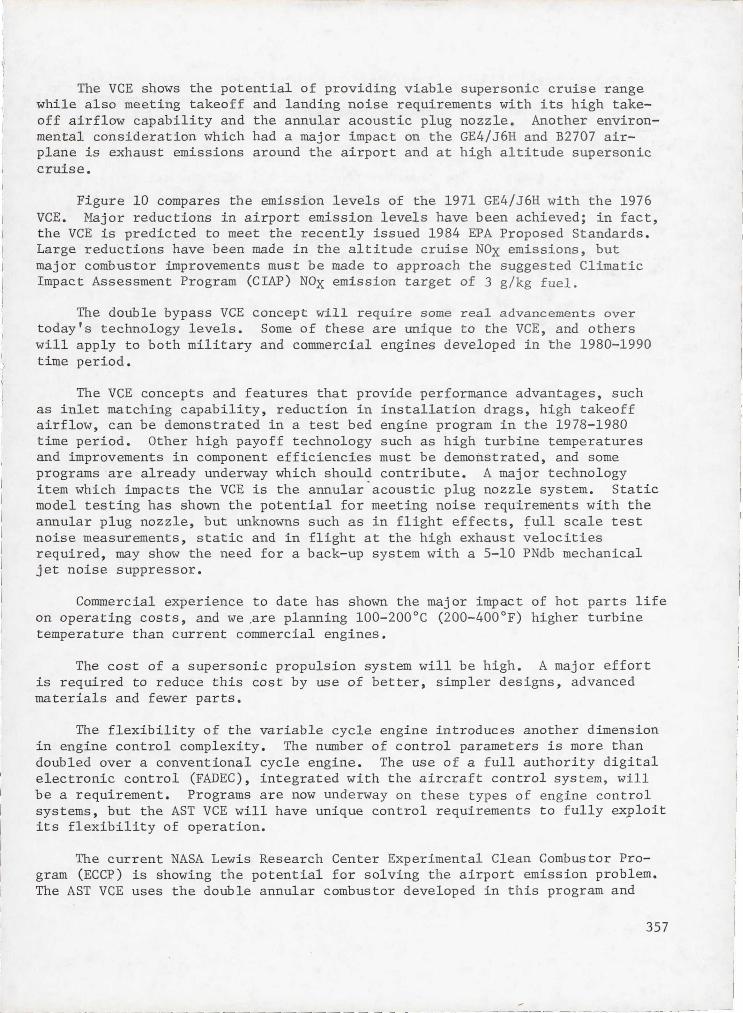
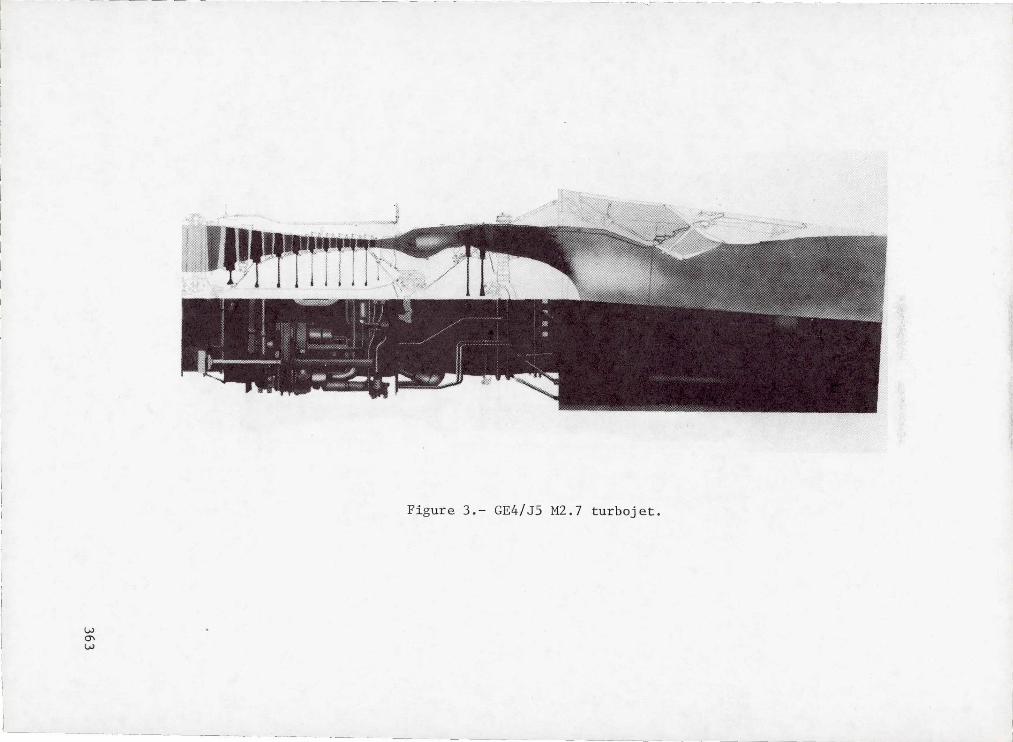
The GE4 development program, up until its cancellation in 1971, had accu-mulated 1800 engine test hours on ten nameplate engines, with over 200 hoursof simulated altitude operation at Mach 2.7 inlet conditions. Table I showsthe GE4/J5 test engine cycle, and figures 1 and 2 show test engines prior toinstallation in the test cell and on test at the Peebles Test Center.
A cross section of the GE4/J5 engine is shown on figure 3. The engine isa single rotor afterburning turbojet with eleven turbomachinery stages, anduses a two stage ejector nozzle (TSEN) to pump secondary air for nacelle cool-ing. The GE4/J5 engine was designed for afterburning takeoff and supersoniccruise at Mach 2.7 using partial afterburning. The afterburning takeoffresulted in noise levels of approximately 120 EPNdb.
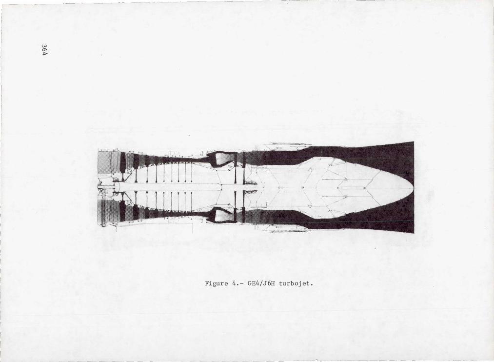
The environmental impact of the GE4/J5 afterburning turbojet in the B2707airplane, noise levels, emissions, etc. became a major problem during thedevelopment program. Extensive studies resulted in the selection of the GE4/J6H dry turbojet for the production engine configuration (see table II). TheGE4/J6H was designed to come close to FAR 36 takeoff noise by providing a hightakeoff airflow of 408 kg/sec (900 lbs/sec) at an exhaust velocity of 762 m/sec(2500 ft/sec) to meet the required takeoff thrust. Figure 4 shows a crosssection of the GE4/J6H, which is similar to the GE4/J5P, that is, basic enginescaled up in airflow and increased turbine temperature, with a new annular plugexhaust system with a retractable 10 PNdb chute type mechanical jet noise sup-pressor, (see figure 5), and no afterburner system. The large airflow sizeprovided the thrust required for dry power climb and acceleration and super-sonic cruise, but the large engine size and weight reduced the range of theB2707 airplane.
At this point in the development of the engine and airplane, the programwas cancelled.
In 1972, the National Aeronautics and Space Administration (NASA) spon-sored study efforts by aircraft and engine manufacturers to identify neededtechnology for supersonic cruise vehicles aimed at the start of full scaledevelopment in the 1980-1985 time period. Under contracts from NASA Lewis
354

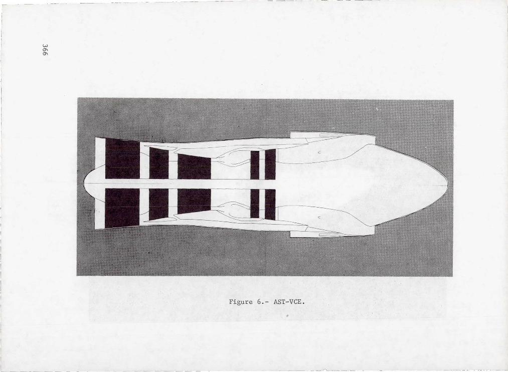
Research Center, General Electric has conducted Advanced Supersonic PropulsionSystem Technology Studies (AST). These studies have screened conventional andvariable cycle concepts and combined features of both types into a variablecycle engine that has characteristics suited for sustained supersonic cruise,while also providing inlet flow matching capability over a wide range of air-flows. The AST VCE is basically a low bypass ratio (0.35) dual rotor turbofanengine with a low temperature augmentor, designed for dry power supersoniccruise, using the afterburner for transonic climb and acceleration only. Attakeoff conditions (see table III) the bypass ratio is almost twice the super-sonic cruise level with airflow to provide acceptable FAR 36 noise levels andthrust. Figure 6 shows a schematic of the double bypass VCE concept. Thebasic differences between the VCE and a conventional turbofan engine are theseparation of the fan into two blocks with an outer bypass duct between thefan blocks, and the normal bypass duct after the second fan block. For thelow noise takeoff mode the front block of the fan is set at its maximum flowconfiguration. The second fan block is operated to tailor the jet exhaustvelocity and flow to produce the desired thrust/noise relationships for take-off. During subsonic cruise operation the front fan block is set to providethe best match between inlet spillage and internal performance. In this modethe second fan block is set to provide the proper cruise thrust. The inletairflow can be maintained down to the required subsonic cruise thrust require-ment, which practically eliminates inlet spillage drag, and because of thehigh flow also reduces the afterbody drag. The effect of the increased by-pass ratio and reduction of installation drag decreases the installed specificfuel consumption (SFC) by about 15%.
In the climb/acceleration and supersonic cruise modes, the front blockfan is set to meet the aircraft inlet flow supply, and the rear block fan andhigh pressure compressor are set to pass all of the front block fan flow, andthe engine operates the same as the nominal 0.35 bypass ratio turbofan engine.An advantage of the split fan configuration, beyond its inlet matching capa-bility, is that for high takeoff airflow, only the front block fan and lowpressure turbine are affected, and a large weight saving is realized over theweight of a conventional turbofan engine sized for the same takeoff airflowand noise level.
A major effort has been made to simplify the engine and exhaust system toreduce cost and weight and increase reliability. The cycle was establishedfor dry (non afterburning) takeoff and supersonic cruise, and to require onlytwo turbine stages. The choice of mixed flow eliminates the need for a sophis-ticated high performance duct burner and requires only a very simple climbacceleration low temperature rise augmentor. The low bypass ratio mixed flowselection for supersonic operation also assures inlet compatibility. Theintroduction of the annular jet noise suppression concept on the VCE resultedin a simpler, lighter weight exhaust system with fewer movable parts and actu-ation systems. These and other improvements have resulted in a lighter, morereliable engine than the CE4 turbojets. A continuing effort on weight, costreduction and increased reliability through simpler design will show furtherimprovements in the future.
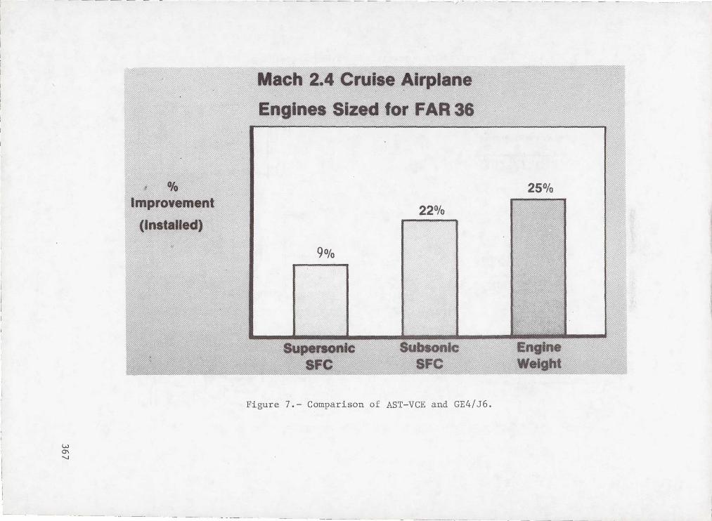
To compare the propulsion system advances from the GE4/J6H of 1971 to the
355
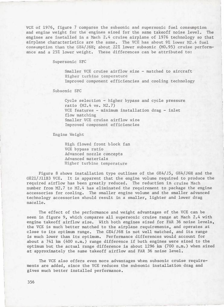
VCE of 1976, figure 7 compares the subsonic and supersonic fuel consumptionand engine weight for the engines sized for the same takeoff noise level. Theengines are installed in a Mach 2.4 cruise airplane of 1976 technology so thatairplane characteristics are the same. The VCE has about 9% lower M2.4 fuelconsumption than the GE4/J6H; about 22% lower subsonic (M0.95) cruise perform-ance and a 25% lower weight. These differences can be attributed to:
Supersonic SFC
Smaller VCE cruise airflow size - matched to aircraftHigher turbine temperatureImproved component efficiencies and cooling technology
Subsonic SFC
Cycle selection - higher bypass and cycle pressureratio (M2.4 vs. M2.7)VCE features - minimum installation drag - inletflow matchingSmaller VCE cruise airflow sizeImproved component efficiencies
Engine Weight
High flowed front block fanVCE bypass ratioAdvanced nozzle conceptsAdvanced materialsHigher turbine temperature
Figure 8 shows installation type outlines of the GE4/J5, GE4/J6H and theGE21/JllB3 VCE. It is apparent that the engine volume required to produce therequired airflow has been greatly reduced. The reduction in cruise Machnumber from M2.7 to M2.4 has eliminated the requirement to package the engineaccessories for cooling. The smaller engine volume and the smaller advancedtechnology accessories should result in a smaller, lighter and lower dragnacelle.
The effect of the performance and weight advantages of the VCE can beseen in figure 9, which compares all supersonic cruise range at Mach 2.4 withengine takeoff airflow size. With both engines sized for FAR 36 noise levels,the VCE is much better matched to the airplane requirements, and operates atclose to its optimum range. The GE4/J6H is not well matched, and its rangeis much lower than its optimum. Performance differences would account forabout a 741 km (400 n.m.) range difference if both engines were sized to theoptimum but the actual range difference is about 1296 km (700 n.m.) when sizedat approximately the same takeoff airflow and FAR 36 noise level.
The VCE also offers even more advantages when subsonic cruise require-ments are added, since the VCE reduces the subsonic installation drag andgives much better installed performance.
356
The VCE shows the potential of providing viable supersonic cruise rangewhile also meeting takeoff and landing noise requirements with its high take-off airflow capability and the annular acoustic plug nozzle. Another environ-mental consideration which had a major impact on the GE4/J6H and B2707 air-plane is exhaust emissions around the airport and at high altitude supersoniccruise.
Figure 10 compares the emission levels of the 1971 GE4/J6H with the 1976VCE. Major reductions in airport emission levels have been achieved; in fact,the VCE is predicted to meet the recently issued 1984 EPA Proposed Standards.Large reductions have been made in the altitude cruise NOg emissions, butmajor combustor improvements must be made to approach the suggested ClimaticImpact Assessment Program (CIAP) NOg emission target of 3 g/kg fuel.
The double bypass VCE concept will require some real advancements overtoday's technology levels. Some of these are unique to the VCE, and otherswill apply to both military and commercial engines developed in the 1980-1990time period.
The VCE concepts and features that provide performance advantages, suchas inlet matching capability, reduction in installation drags, high takeoffairflow, can be demonstrated in a test bed engine program in the 1978-1980time period. Other high payoff technology such as high turbine temperaturesand improvements in component efficiencies must be demonstrated, and someprograms are already underway which should_ contribute. A major technologyitem which impacts the VCE is the annular acoustic plug nozzle system. Staticmodel testing has shown the potential for meeting noise requirements with theannular plug nozzle, but unknowns such as in flight effects, full scale testnoise measurements, static and in flight at the high exhaust velocitiesrequired, may show the need for a back-up system with a 5-10 PNdb mechanicaljet noise suppressor.
Commercial experience to date has shown the major impact of hot parts lifeon operating costs, and we,are planning 100-200°C (200-400°F) higher turbinetemperature than current commercial engines.
The cost of a supersonic propulsion system will be high. A major effortis required to reduce this cost by use of better, simpler designs, advancedmaterials and fewer parts.
The flexibility of the variable cycle engine introduces another dimensionin engine control complexity. The number of control parameters is more thandoubled over a conventional cycle engine. The use of a full authority digitalelectronic control (FADEC), integrated with the aircraft control system, willbe a requirement. Programs are now underway on these types of engine controlsystems, but the AST VCE will have unique control requirements to fully exploitits flexibility of operation.
The current NASA Lewis Research Center Experimental Clean Combustor Pro-gram (ECCP) is showing the potential for solving the airport emission problem.The AST VCE uses the double annular combustor developed in this program and
357

meets the proposed 1984 EPA standards. The high altitude cruise NOg emissionsrequire a new combustor technology to meet CIAP targets. These combustors.willrequire major research and development effort to achieve a practical designwhich meets the engine operating requirements, and both airport and altitudecruise emission levels.
The major question, not yet answered is, if all of these technology goalsare attained, can we have a commercial supersonic cruise vehicle which willmake money for the airlines?
The answer to this question will require a continuing major effort torefine the variable cycle engine, and match the airplane and propulsion systemin an integrated economically viable commercial transport.
358
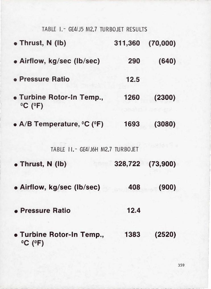
TABLE I.- GE41J5 M2.7 TURBOJET RESULTS
• Thrust, N (lb) 3115360 (709000)
• Airflow, kg/sec (lb/sec) 290 (640)
• Pressure Ratio 12.5
• Turbine Rotor-In Temp., 1260 (2300)OC (OF)
• A/B Temperature, O C (OF)
1693 (3080)
TABLE II.- GE41J6H M2.7 TURBOJET
• Thrust, N (lb) 3285722 (739900)
• Airflow, kg/sec (lb/sec) 408 (900)
• Pressure Ratio 12.4
• Turbine Rotor-In Temp., 1383
(2520)
OC (OF)
359

TABLE I f I. - AST-VCE M2.4
• Airflow at T/O,kg/sec (lb/sec)
• Bypass at T/O
• Pressure Ratio
• Turbine Rotor-In Temp.,oC
(OF)
380 (840)
0.8
17.3
1538 ( 2800)
• A/B Temperature, °C (OF)
1038 (1900)
360

a,boaa^
LnCIO
tic7ia^
w
361
aima^vawwNvbA
w
362
•nONnNUl
hf4C7I
cnOD
W
363
.r,0xwc7W^4co
w
364

UNC1
r-IU.bOS4
OUaaxc^v;o^
w
365
wUH6aD.m
ay
w
366
rrw.
xo•aMr
WC4
cW
hwbwUI
E-^cn6wOGOtOUn
a)
!4
w
367

I I \
\ I I
l
I , __
------ --------- --
I I
~~~~-- ~---~.--_~L I i
7
___ .J-
GE4{J5P
Sideline HolM FAR 36 · 10
GE4/J6H
Sideline Noise FA.R 36-0
GE21/J11B3 .
Sideline Noise FAR 36-0
Figure 8.- Engine installation comparison.
--------"- ----- ~-- ---- ------- ----
, -.~--~-~-

I r
4t
r-
^/ E
i(0 O
M a
N
Qi*'
N(L
cc
QLL
LL
40
f40
40' ^ WRR
1ttt
LLNdL.
0mMIN-
0̂+w
^it~Q)a^0t~rouwUIw
vim
tU EEc ,x
4^
369

•
^^y^Appi
u, M
I^
au
bD
oi
.^x
O
WWWNM^
m
Ln
u ^
Crj
U C
dr
7, +1U
V^14
v
N^
G N
Qw'
'Ha
Np bD
Wo
aqr
W00
p
^
oui
C7>
rQ.
CO
Ndx
r
F4
r^
prw
U
4-1Q)
^4C
GO
r^
u o
rNI
0.ir
rn
c0
^,
°'a
> HQ
^aI r.
Ow^}
•rl
oO
C /(A
• Ti
ujN
OAM
Wg
wr
370