advanced structures set manual
TRANSCRIPT
�
PASCO Structures System
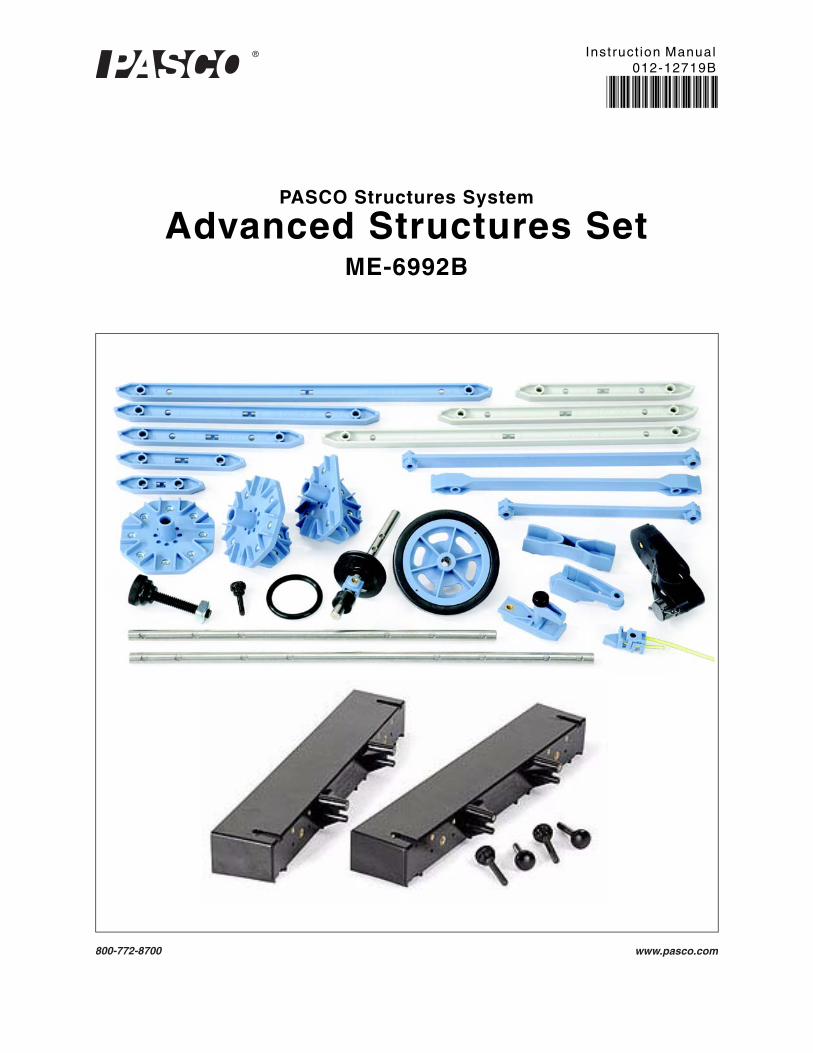
Advanced Structures SetME-6992B
Instruct ion Manual012-12719B
*012-12719*

� ii
The PASCO Advanced Structures Set includes the ME-6988A Force Structures Bracket for connecting a struc-ture to a PASCO Force Platform.

� iii
Table of Contents
Included Items . . . . . . . . . . . . . . . . . . . . . . . . . . . . . . . . . . . . . . . . . . . . . . . . . . . . . . . . . 1
Related and Recommended Equipment . . . . . . . . . . . . . . . . . . . . . . . . . . . . . . . . . . . . . 2
Introduction . . . . . . . . . . . . . . . . . . . . . . . . . . . . . . . . . . . . . . . . . . . . . . . . . . . . . . . . . . . 2
About the Components . . . . . . . . . . . . . . . . . . . . . . . . . . . . . . . . . . . . . . . . . . . . . . . . . . 3
Adding Load Cells . . . . . . . . . . . . . . . . . . . . . . . . . . . . . . . . . . . . . . . . . . . . . . . . . . . . . . 5
Properties of I-Beams . . . . . . . . . . . . . . . . . . . . . . . . . . . . . . . . . . . . . . . . . . . . . . . . . . . 6
Simple Triangles . . . . . . . . . . . . . . . . . . . . . . . . . . . . . . . . . . . . . . . . . . . . . . . . . . . . . . . 6
Trusses . . . . . . . . . . . . . . . . . . . . . . . . . . . . . . . . . . . . . . . . . . . . . . . . . . . . . . . . . . . . . . 7
Common Truss Bridges . . . . . . . . . . . . . . . . . . . . . . . . . . . . . . . . . . . . . . . . . . . . . . . . . . 8
Different Scales . . . . . . . . . . . . . . . . . . . . . . . . . . . . . . . . . . . . . . . . . . . . . . . . . . . . . . . . 8
Measuring Bridge Deflection Under Load . . . . . . . . . . . . . . . . . . . . . . . . . . . . . . . . . . . . 9
Bridge Challenges for Students . . . . . . . . . . . . . . . . . . . . . . . . . . . . . . . . . . . . . . . . . . . 10
Measuring Static and Dynamic Loading . . . . . . . . . . . . . . . . . . . . . . . . . . . . . . . . . . . . 10
Forces on a Boom . . . . . . . . . . . . . . . . . . . . . . . . . . . . . . . . . . . . . . . . . . . . . . . . . . . . . 11
Human Leg Model . . . . . . . . . . . . . . . . . . . . . . . . . . . . . . . . . . . . . . . . . . . . . . . . . . . . . 13
Teeter Totter . . . . . . . . . . . . . . . . . . . . . . . . . . . . . . . . . . . . . . . . . . . . . . . . . . . . . . . . . 15
Human Back Model . . . . . . . . . . . . . . . . . . . . . . . . . . . . . . . . . . . . . . . . . . . . . . . . . . . . 17
Tower Crane . . . . . . . . . . . . . . . . . . . . . . . . . . . . . . . . . . . . . . . . . . . . . . . . . . . . . . . . . 19
Human Arm Model . . . . . . . . . . . . . . . . . . . . . . . . . . . . . . . . . . . . . . . . . . . . . . . . . . . . . 21
Angle Crane. . . . . . . . . . . . . . . . . . . . . . . . . . . . . . . . . . . . . . . . . . . . . . . . . . . . . . . . . . 23
Catapult . . . . . . . . . . . . . . . . . . . . . . . . . . . . . . . . . . . . . . . . . . . . . . . . . . . . . . . . . . . . . 25
Camelback Truss Bridge and Multilength Combinations . . . . . . . . . . . . . . . . . . . . . . . . 27
Truss Bridge with Cross Bracing and Trestle with Cross Bracing . . . . . . . . . . . . . . . . . 28
PAStrack Trestle with Cross Bracing . . . . . . . . . . . . . . . . . . . . . . . . . . . . . . . . . . . . . . . 29
Tower with Cross Bracing . . . . . . . . . . . . . . . . . . . . . . . . . . . . . . . . . . . . . . . . . . . . . . . 30
Rubber Band Powered “Car” . . . . . . . . . . . . . . . . . . . . . . . . . . . . . . . . . . . . . . . . . . . . . 31

�
Advanced Structures Set
iv
Spares Part Numbers and Summary of Extra Equipment . . . . . . . . . . . . . . . . . . . . . . . 32
Bridges That Require an Advanced Set and a Bridge Set. . . . . . . . . . . . . . . . . . . . . . . 33
I-Beam Suspension Bridge Details . . . . . . . . . . . . . . . . . . . . . . . . . . . . . . . . . . . . . . . . 34
I-Beam Suspension Bridge End Assembly . . . . . . . . . . . . . . . . . . . . . . . . . . . . . . . . . . 35
I-Beam Suspension Bridge Tower . . . . . . . . . . . . . . . . . . . . . . . . . . . . . . . . . . . . . . . . . 36
I-Beam Suspension Bridge Road Bed Assembly. . . . . . . . . . . . . . . . . . . . . . . . . . . . . . 37
Flexible I-Beam Suspension Bridge. . . . . . . . . . . . . . . . . . . . . . . . . . . . . . . . . . . . . . . . 37
Flat Beam Suspension Bridge . . . . . . . . . . . . . . . . . . . . . . . . . . . . . . . . . . . . . . . . . . . . 38
Cable Stayed Bridge . . . . . . . . . . . . . . . . . . . . . . . . . . . . . . . . . . . . . . . . . . . . . . . . . . . 39
Cable Stayed Bridge Details . . . . . . . . . . . . . . . . . . . . . . . . . . . . . . . . . . . . . . . . . . . . . 40
Baltimore Bridge and Arched Causeway Bridge Details 1. . . . . . . . . . . . . . . . . . . . . . . 41
Arch Truss Bridge . . . . . . . . . . . . . . . . . . . . . . . . . . . . . . . . . . . . . . . . . . . . . . . . . . . . . 42
Cantilevered Truss Bridge . . . . . . . . . . . . . . . . . . . . . . . . . . . . . . . . . . . . . . . . . . . . . . . 43
Tied Arch Bridge with Cross Bracing . . . . . . . . . . . . . . . . . . . . . . . . . . . . . . . . . . . . . . . 44
Double Tied Arch Bridge with Flexible I-Beams. . . . . . . . . . . . . . . . . . . . . . . . . . . . . . . 45
PAStrack Cable Stayed Bridge . . . . . . . . . . . . . . . . . . . . . . . . . . . . . . . . . . . . . . . . . . . 46
Cable Stayed Bridge Construction Suggestions . . . . . . . . . . . . . . . . . . . . . . . . . . . . . . 47
Resonance Structures: Beam and Tower . . . . . . . . . . . . . . . . . . . . . . . . . . . . . . . . . . . 48
Force Platform Structures Bracket. . . . . . . . . . . . . . . . . . . . . . . . . . . . . . . . . . . . . . . . . 51
Technical Support, Warranty, and Copyright . . . . . . . . . . . . . . . . . . . . . . . . . . . . . . . . . 54
Advanced Structures SetME-6992B
� 1
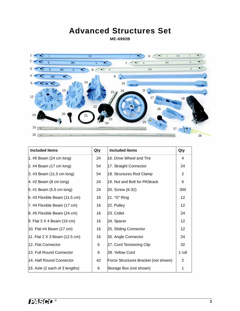
Included Items Qty Included Items Qty
1. #5 Beam (24 cm long) 24 16. Drive Wheel and Tire 4
2. #4 Beam (17 cm long) 54 17. Straight Connector 24
3. #3 Beam (11.5 cm long) 54 18. Structures Rod Clamp 2
4. #2 Beam (8 cm long) 24 19. Nut and Bolt for PAStrack 6
5. #1 Beam (5.5 cm long) 24 20. Screw (6-32) 300
6. #3 Flexible Beam (11.5 cm) 16 21. “O” Ring 12
7. #4 Flexible Beam (17 cm) 16 22. Pulley 12
8. #5 Flexible Beam (24 cm) 16 23. Collet 24
9. Flat 3 X 4 Beam (19 cm) 16 24. Spacer 12
10. Flat #4 Beam (17 cm) 16 25. Sliding Connector 12
11. Flat 2 X 3 Beam (12.5 cm) 16 26. Angle Connector 24
12. Flat Connector 6 27. Cord Tensioning Clip 32
13. Full Round Connector 6 28. Yellow Cord 1 roll
14. Half Round Connector 42 Force Structures Bracket (not shown) 2
15. Axle (2 each of 3 lengths) 6 Storage Box (not shown) 1
16
17
19
14
8
5
12
9
1513 11
10
3
7
6
4
2
1
15
15
18
20 21
22
2324
26
25
27
28

�
Advanced Structures Set Introduct ion
2 012-12719B
The ME-6992B Advanced Structures Set consists of items from the following components of the PASCO Struc-tures System.
Other PASCO equipment is closely related to the Advanced Structures Set..
*See the PASCO catalog or PASCO web site (www.pasco.com) for more information
Introduction
The ME-6992B Advanced Structures Set is one part of the PASCO Structures System. The Advanced Structures Set can be used as a stand-alone set and it can also be combined with other parts of the PASCO Structures Sys-tem. The Load Cell and Amplifier Set (PS-2199) can be added to measure compression and tension forces in the structure members and other sets of plastic parts are available.
Other parts of the PASCO Structures System include the following:
Physics Structures Set (ME-6989) - A set of structure items (e.g., beams, connectors, screws) and other equip-ment designed for studying kinematics, momentum, energy, and rotation.
Truss Set (ME-6990) - A small set of beams, connectors, and screws for building trusses.
Bridge Set (ME-6991) - A larger set with road bed and cables for building bridges and roller coasters.
Load Cell Amplifier (PS-2198) - Can plug in up to six Load Cells; requires a PASPORT interface to connect to the USB port of a computer.
Load Cell and Amplifier Set (PS-2199) - Load Cell Amplifier (PS-2198) with four 100 N Load Cells (PS-2200).
ME-6985 Flexible I-Beam Set ME-6996 Cord Lock Spares
ME-6986 Structures Rod Clamp (2) ME-6997 Full Round Connectors
ME-6987 Flat Structures Members ME-6998A Axle Spares
ME-6993 Truss Set Members ME-6999A Angle Connectors
ME-6994 Truss Set Screws 740-162 Storage Box (12 quart)
Related Equipment Related Equipment
PS-2198 Load Cell Amplifier ME-6989 Physics Structures Set
PS-2199 Load Cell and Amplifier Set ME-6990 Truss Set
PS-2200 100-N Load Cell ME-6991 Bridge Set
PS-2201 5-N Load Cell ME-6995 Road Bed Spares
PS-2205 Displacement Sensor PASPORT Interfaces*
PS-2206 Dual Load Cell Amplifier Data Acquisition Software*
Recommended Equipment Recommended Equipment
Hooked Mass Set (SE-8759) Large Slotted Mass Sets (ME-7566 and ME-7589)
Mass and Hanger set (ME-8979) Angle Indicator (ME-9495A)
PASPORT Force Platform (PS-2141) 2-Axis Force Platform (PS-2142)
�
Model No. ME-6992B About the Components
3012-12719B
100 N Load Cell (PS-2200) - Strain gauges mounted on a beam with no electronics so a Load Cell requires a Load Cell Amplifier (PS-2198) or Dual Load Cell Amplifier PS-2206).
5 N Load Cell (PS-2201) - Strain gauges mounted on a beam with no electronics so a Load Cell requires a Load Cell Amplifier or Dual Load Cell Amplifier.
Displacement Sensor (PS-2205) - A PASPORT Sensor and a digital displacement indicator designed to measure the deflection of parts of a structure such as a truss or a bridge.
Dual Load Cell Amplifier (PS-2206) - Can plug in one or two Load Cells; requires a PASPORT interface to connect to the USB port of a computer.
About the Components
Beams
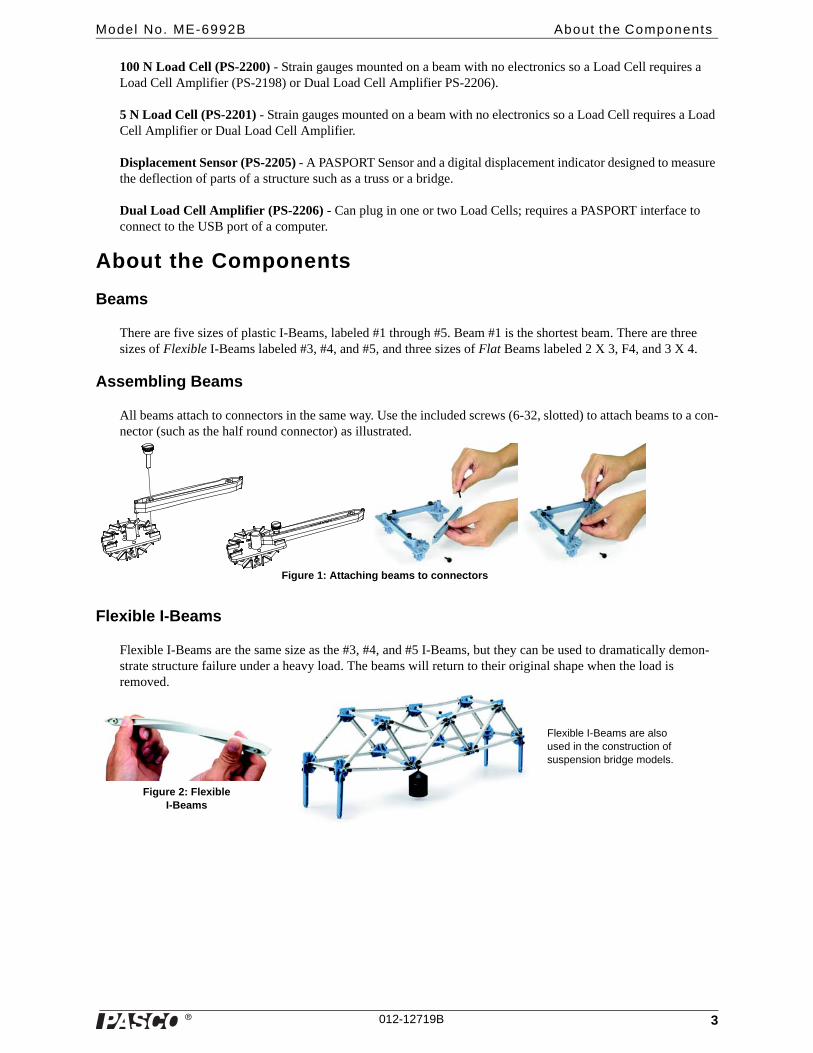
There are five sizes of plastic I-Beams, labeled #1 through #5. Beam #1 is the shortest beam. There are three sizes of Flexible I-Beams labeled #3, #4, and #5, and three sizes of Flat Beams labeled 2 X 3, F4, and 3 X 4.
Assembling Beams
All beams attach to connectors in the same way. Use the included screws (6-32, slotted) to attach beams to a con-nector (such as the half round connector) as illustrated.
Flexible I-Beams
Flexible I-Beams are the same size as the #3, #4, and #5 I-Beams, but they can be used to dramatically demon-strate structure failure under a heavy load. The beams will return to their original shape when the load is removed.
Figure 1: Attaching beams to connectors
Figure 2: Flexible I-Beams
Flexible I-Beams are also used in the construction of suspension bridge models.

�
Advanced Structures Set About the Components
4 012-12719B
Flat Beams
Flat Beams are used for cross-bracing.
Attaching Cords
When attaching cords for lateral bracing or for suspension or cable-stayed bridges, Cord Tensioning Clips are used to assist in adjusting the tension in the cords.
The Cord Clip does not come apart. It is best to thread the cord through the clip before the clip is installed on the bridge or structure. Prepare to thread the cord by holding the top half of the clip as shown in Figure 4a so the two halves of the clip will separate, leav-ing an opening through which the cord is threaded. The cord is inserted into the end opposite the pointed end of the clip. The cord should be looped back through the clip as shown in Figure 4c. Then the Cord Clip can be used in the structure, using the attachment screw to tighten the clip shut. To adjust the cord tension, loosen the screw and pull on the cord to the desired tension and then tighten the screw.
Connectors
Half Round Connector: The half round connector has eight slots, labeled A through H, for accepting beams.
Full Round Connector: The full round connector has eleven slots, labeled A through H and X, Y, and Z, for attaching beams
Flat Connector: The flat connector has eight slots, labeled A through E, and X, Y, and Z, for attaching beams.
Straight Connector: The straight connector can connect two beams to make a longer beam.
Angle Connector: The angle connector can allow a beam to be con-nected to a half round connector, full round connector, or flat connec-tor at an angle different than zero, 45, or 90 degrees. The Angle Connector also allows for a small adjustment of the length of the beam.
Sliding Connector: The sliding connector allows one beam to be con-nected to another beam at any position along the length of the second beam. To use the sliding connector, loosen the thumbscrew and rotate the top “jaw” to the side. Place the beam onto the lower part of the connector, rotate the top “jaw” into place, and tighten the thumbscrew.
2 X 3 Flat Beams
Figure 3: Flat Beams
#3
#2
Figure 4a: Hold half of the cord clip so the two halves separate
Figure 4b: Loop the cord back through the
cord clip
Figure 4c: The cord goes around the
screw hole
Figure 4d: The cord clip is ready to be attached to the
structure using a screw
Half Round
Full Round Flat
Straight Angle
Figure 5: Connectors
Sliding
I-Beam #1
“Jaw”
Top view

�
Model No. ME-6992B Adding Load Cel ls
5012-12719B
Nut and Bolt for PAStrack: The square nut and bolt can be used with a flat connector to fasten a bridge or other structure to the PASCO PAStrack (see the PASCO catalog or web site at www.pasco.com for information about PAStrack equipment.)
Axles, Pulleys, Spacers, Collets, and Drive Wheels
Axles: There are two each of three different lengths: 10.4 cm (4.1 in), 21.3 cm (8.4 in), and 26.6 cm (10.5 in). Each axle is 0.635 cm (0.250 in) in diameter.
Pulleys: There are twelve pulleys, each 3.175 cm (1.250 in) in diameter and 0.558 cm (0.220 in) wide. To make a wheel, put one of the “O” rings into the pulley’s groove.
Spacers: There are twelve spacers, each 0.635 cm (0.250 in) inside diame-ter, 1.25 cm (0.50 in) outside diameter, and 0.635 cm (0.250 in) wide.Col-lets: There are twenty-four collets that can be used with screws (6-32) to hold pulleys and spacers in place on an axle.
Drive Wheel with Tire: There are four drive wheels with tires. The drive wheel can be attached to an axle using a thumbscrew. To attach the wheel firmly to the axle, line up a hole on the axle with the thumbscrew hole on the wheel. If the rubber tire is removed, the wheel can be used as a large pul-ley.
Force Platform Structure (ME-6988A)
The PASCO model ME-6988A Force Platform Structures Bracket includes two brackets and four thumbscrews. The adapter bracket is designed to connect members of the PASCO Structures System to a PASCO Force Platform (not included). The brackets can also serve as foundation plates for larger structure models. (Please see the Force Platform Structures Bracket instruction sheet for more information.)
Adding Load Cells
To measure the compression and tension forces in individual members, add load cells (e.g., PASCO Model PS-2200) to any PASCO Structure. Replace a beam with two shorter beams and a load cell.
#5 beam = load cell + two #3 beams
#4 beam = load cell + two #2 beams
#3 beam = load cell + two #1 beams
Use thumbscrews to attach two beams to a load cell as shown in Figure 8.
When using load cells, assemble your structure with the screws loose. This will simplify the analysis by ensuring that the members experience only tension and compression without moments.
See the instructions that came with the load cells for details about how to connect the load cells to an interface or datalogger and collect data.
Figure 6: Nut and Bolt for PAStrack
Figure 7: Axle items
Axle
O-Ring
PulleySpacer
Collet
Drive Wheel
Figure 8: A load cell combined with two #2 beams is the same length as a #4 beam

�
Advanced Structures Set Propert ies of I -beams
6 012-12719B
Example: Bridge with Load Cells
The bridge shown in Figure 9 incorporates six load cells to measure the tension or compression in vari-ous members. A hanging mass is used to apply load. The mass is adjusted so that the compression in one of the legs is 1.0 N. Compression is registered as a positive value and tension as a negative value.
If the screws are loose, the theoretical analysis of the bridge can be carried out by assuming that the net force at each node is zero. Thus, the vertical component of compression in the left-most diagonal member must be 1 N (to oppose the force applied by the leg). The horizontal component must also be 1 N since the member is at a 45° angle. The predicted resultant force is:
The actual measured force confirms the theory.
Calibration of Load Cells
Load cells are factory calibrated; however, you can re-calibrate them in software or on the datalogger. Assemble the fixture shown in Figure 10 to support the load cell. See the documentation for your software or datalogger for instructions.
When calibrating a load cell, it is necessary to apply a known load. Hold or clamp the fixture at the edge of a table and hang a mass from it as shown.
Note that the hanging mass applies tension to the load cell; therefore the known force that you enter into the software or datalogger should be a negative value. For example, if the mass is 1.0 kg, the applied force is -9.8 N.
Properties of I-beams
Figure 11 shows the difference between the X and Y bending moments of an I-beam.
Simple Triangles
Most structures are made of isosceles right tri-angles as shown in Figure 12.
Figure 9: Bridge with Load Cells
1.0 N 2 1.0 N 2+ 1.4 N=
Figure 10: Calibration fixture
Load Cell
Mass
Figure 11: Bending an I-Beam
#4
#4
#5#4
#3
#3
#3#2
#2
#2#1
#1
Figure 12: (Left) A triangle made from a #5 beam and two #4 beams. (Right) Combinations of beams to make triangles.
Half Round connector

�
Model No. ME-6992B Trusses
7012-12719B
Trusses
Kingpost Truss
Figure 13 shows a simple king-post truss made from #5 and #4 beams. Use a hanging mass to apply a load.
Lay the kingpost truss on the table to compare its horizontal and vertical stiffness.
To build a three-dimensional structure, connect two trusses with #4 beams (Figure 14).
Add cross bracing to increase stiffness.
Queenpost Truss
To make a queenpost truss, separate the kingpost truss in the middle and add a square section..
Legs can be added to any truss or bridge (Figure 15).
Roof Truss
Use #4 and #5 beams to build a simple roof truss or a roof truss structure with legs.
Figure 13: A simple kingpost truss
#4
#4
#4
#5 #5
Figure 14: (Left) A three-dimensional kingpost truss structure. (Right) Kingpost truss with cross bracing.
#5 #5
#4
#4
#4
#4
#4#4
Figure 15: (Left) Diagram of queenpost truss (Middle) Queenpost truss (Right) Queenpost truss with legs
#4 #4#4#4
#4 #4
#5
#5#5
Figure 16: Roof truss

�
Advanced Structures Set Common Truss Br idges
8 012-12719B
Common Truss Bridges
Warren Bridge
The Warren Bridge (Figure 17) is a simple type of bridge consisting of a series of triangles. However, a simple Warren Bridge is not practical for supporting a deck (road bed). Vertical members can be added to support the deck. Additional verticals can support an upper deck.
To make a free-standing bridge, begin by laying out one side of the bridge on a table. Then build the other side of the bridge. Join the two sides of the bridge attaching the floor beams and the top cross beams. Use additional members as piers to support the bridge. (Figure 18).
Different Scales
It is possible to build bridges of two different scales. Figure 19 shows a Warren with Verticals built to two different scales.
In spanning a particular distance, why wouldn’t you use the smaller scale bridge and add more panels? An examination of the forces in the mem-bers of each size bridge will give the answer. If the smaller and larger bridges have the same num-ber of panels and experience the same load, the forces in any member of the smaller bridge is the same as the same member in the larger bridge. Each additional panel is submitted to larger forces. This can be explored using load cells. See the section on Measurement of Static and Dynamic Loads
Figures 20 and 21 show different bridges. Investi-gate how the forces in these bridges differ from the Warren.
Figure 18: Free-standing Warren bridge
Figure 17: (Top) Warren bridge (Middle) Warren with deck verticals (Bottom) Warren with verticals
#4
#5
#3
#3
#3
#4
#3
#3
#4
#5
Figure 20: (Top) Pratt. (Bottom) Howe
Figure 19: Smaller and larger scale Warren with verticals
#3
#4
#5
#3
Figure 21: Free-standing Howe

�
Model No. ME-6992B Measur ing Br idge Def lect ion Under Load
9012-12719B
Measuring Bridge Deflection Under Load
Because the members are made of plastic, it is easy to show bending in a bridge using relatively small loads.
Using a Motion Sensor
In Figure 22, the bridge is loaded by hanging a weight (Large Slotted Mass Set, PASCO Model ME-7566) from the center of the bridge. A Motion Sensor (PS-2103) is placed on the floor and pointed up toward the bottom of the weight hanger. A PASPORT interface (in this case, the Xplorer GLX, PS-2002) is used to record the amount of mass and the distance to the bottom of the weight hanger. A graph of the deflection as a function of the load is shown next to Figure 22.
Hint: For the GLX, set the Motion Sensor sample rate to 50 Hz. In the Sensor Setup window, change the ‘Reduce/Smooth Averaging’ from ‘Off’ to ‘5 points’.
Using Load Cells
Figure 23 shows two bridges of the same type but different scale. For a given load the deflection is different. Also note that the forces in some of the members are being measured using load cells to discover the difference caused by the size of the bridge.
Bridge Challenges for Students
Perhaps the best way for students to learn about bridges is to give them a task to accomplish with limited resources by any means possible. Here are two suggestions to challenge your students.
NOTE: Do not attempt to load the bridge to the point of breaking.
Figure 22: (Left) Deflection of bridge under load. (Above) Displacement vs. Mass plotted using
PASCO’s DataStudio software.
Figure 23: (Above) Same load for different scale bridges. (Right) Displacement vs. Mass
�
Advanced Structures Set Measur ing Stat ic and Dynamic Loading
10 012-12719B
Span a Gap
Give each group a set of plastic, half of a Bridge Set or a Truss Set. The goal is to span a gap of 60 cm. Then find the member with the greatest compression and change the design of the bridge to minimize the maximum com-pression.
Least Deflection Under Load
Give each group a Bridge Set. The goal is to span a given distance with a bridge that has the least deflection under load. The bridge is loaded with a particular load that the bridge must be able to bear. The bridge that has the least defection is the winner.
Measuring Static and Dynamic Loading
Static Load
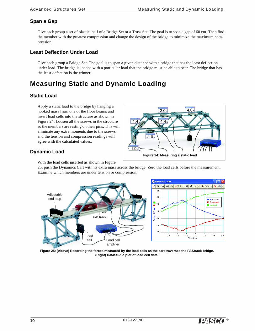
Apply a static load to the bridge by hanging a hooked mass from one of the floor beams and insert load cells into the structure as shown in Figure 24. Loosen all the screws in the structure so the members are resting on their pins. This will eliminate any extra moments due to the screws and the tension and compression readings will agree with the calculated values.
Dynamic Load
With the load cells inserted as shown in Figure 25, push the Dynamics Cart with its extra mass across the bridge. Zero the load cells before the measurement. Examine which members are under tension or compression.
Figure 24: Measuring a static load
Figure 25: (Above) Recording the forces measured by the load cells as the cart traverses the PAStrack bridge. (Right) DataStudio plot of load cell data.
PAStrack
Load cell Load cell
amplifier
Adjustable end stop

� 11
Model No. ME-6992B Forces on a Boom
Forces on a Boom
Full Round
Angle Connector
Hooked Mass
Slotted Masses
Straight Connector
Half Round
Angle Connector
Axle (Medium)
Screw
Half Round
Half Round
#2
#3#4
#4
#3
#5
#5
Load Cell
#3
#1
#1
Boom Detail
Load Cell Detail
Cord
Cord
Cord
Attach a cord from the Load Cell over the pulley to the boom.
Flat Connector
#2 Stack slotted masses on the flat connector.
Straight Connector
Half Round
#1
Pulley
Axle (Short)
Angle Connector
Half Round
Cord Tensioning
Clip
Full Round
#1
Load CellAngle
Connector
#3
#1
#1
Top Pulley Detail
Half Round
Angle Connector
Full Round #3
#3
#3
Half Round
#1
#1
Extra Equipment Model Extra Equipment Model
Hooked Mass Set SE-8759 Angle Indicator ME-9495
Large Slotted Mass Set ME-7566 Load Cell & Amplifier Set PS-2199

�
Advanced Structures Set Forces on a Boom
12 012-12719B
Forces on a Boom: Details
Load Cells
The “Forces on a Boom” structure is shown with four Load Cells measuring the horizontal and vertical forces of the axle on the base of the boom. The experiment can be performed using only two Load Cells on the base, both on one side, but care must be given to ensure that the boom is centered and balanced side-to-side. The actual force will be two times the measured value.
Suggestions
The triangular support structure for the upper pulley is constructed to allow the cord to be horizontal. By using different components, students can change the height of the pulley and thus vary the angle of the cord. How does that affect the measured forces?
The supporting cord is shown tied to a cross member near the end of the boom. What changes if the cord is moved to the end of the boom or to a cross member closer to the base of the boom?
Angle Indicator
The ME-9495 Angle Indicator can be used both on the cord and on the boom itself.
Force Vector Diagram
The following diagram shows the various forces acting on the boom.
W
Wb
T
Fy
Fx

� 13
Model No. ME-6992B Human Leg Model
Human Leg Model
Load Cell
Full Round
#2
#3
Half Round
Half Round
#1
#1
Half Round
Pulley
Collet
Axle (Medium)
#1
Spacer
Axle (Medium)
Half Round
Screw
Angle Connector
Angle Connector
Straight Connector
#4
#5
#3
#3
Half Round
#1
Half Round
Angle Connector
#3
#5
#5
#3
#1
Flat Connector
#2
Attach cord to this I-beam
Cord
Cord
Angle Connector
#2
Load Cell Detail
“Knee” Detail
Stack masses on the flat connector.
Use a cord tensioning clip to connect a cord to the Load Cell. Put the cord over the pulley and attach the end to the front cross-member of the “knee”.
Extra Equipment Model
Large Slotted Mass Set ME-7566
Large Table Clamp ME-9472
Load Cell & Amplifier Set PS-2199
Angle Connector
#1
Screw
�
Advanced Structures Set Human Leg Model
14 012-12719B
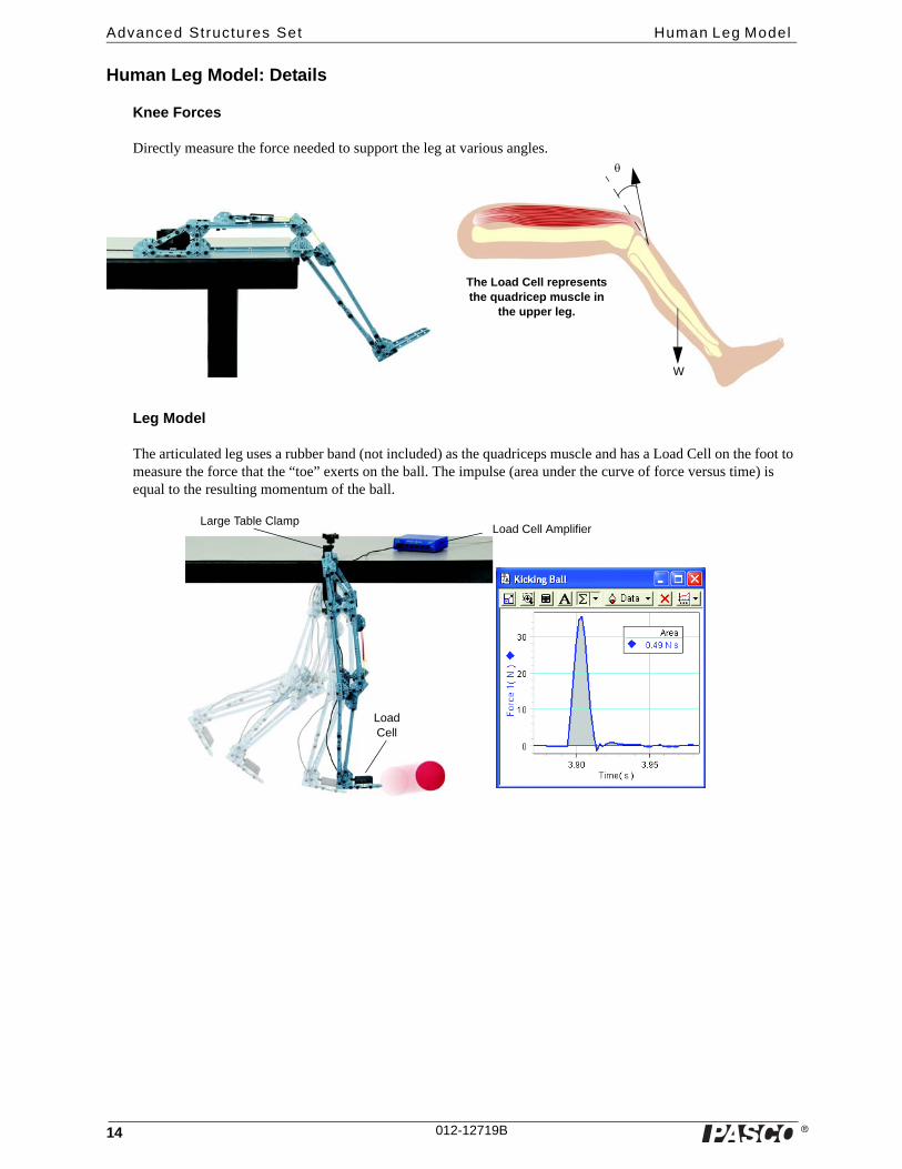
Human Leg Model: Details
Knee Forces
Directly measure the force needed to support the leg at various angles.
Leg Model
The articulated leg uses a rubber band (not included) as the quadriceps muscle and has a Load Cell on the foot to measure the force that the “toe” exerts on the ball. The impulse (area under the curve of force versus time) is equal to the resulting momentum of the ball.
The Load Cell represents the quadricep muscle in
the upper leg.
W
Large Table Clamp
LoadCell
Load Cell Amplifier

� 15
Model No. ME-6992B Teeter Totter
Teeter Totter
Half Round
Half Round
Axle (Medium)
#1
#2
#4
#5
#4
Straight Connector
#4
#4
#4#4
#4
#4
#2
#1
Angle Connector
Half Round
Axle (Medium)
#2
#2
#4#4Use a hanger and mass at this end and a hooked mass at the other end.
Pivot Detail
Short End of Teeter Totter Detail
Extra Equipment Model
Hooked Mass Set SE-8759
Mass and Hanger Set ME-8979

�
Advanced Structures Set Teeter Totter
16 012-12719B
Teeter Totter: Details
Suggestions
Vary the length of the teeter totter by increasing or decreasing the number of segments or sections.
Vary the placement of the pivot: it does not have to be as shown.
Place the hanging masses at different locations.
How will you know that the torque on the right side equals the torque on the left side?
Mass and Hanger
Hooked Mass

� 17
Model No. ME-6992B Human Back Model
Human Back Model
Cord Tensioning Clip
#1
Angle Connector
#3
Load Cell
Axle (Medium)
Half Round
#1
#2
Straight Connector
#4
Angle Connector
Angle Connector
#4
#1
Half Round
#2
#2
Support for slotted masses
#2 Flat Connector
#3
Half Round
#3 #4
#4
Straight Connector
Angle Connector
Half Round
#5 #4
#2#1
#2
Cord
Hooked Mass
Slotted Masses
Load Cell
#4
Lower Back Detail
Cord
Note that the model can be built with fewer than five Load Cells if necessary.
Full Round
Half Round
Axle (Medium)
Pulley
Screw#1
#3
#5 Angle Connector
Angle ConnectorHalf Round
#3
Half Round
#1Full Round
#1
Half Round
Load Cell#3
Full Round
#4
#4
Tie a cord to the cord tensioning clip on the Load Cell. Thread the cord under the pulley, and attach its end to the #2 beam in the middle of the “back”.
Load Cell Detail
Full Round

�
Advanced Structures Set Human Back Model
18 012-12719B
Human Back Model: Details
Force Vector Diagram
The following diagram shows the force vectors acting on the human back model.
Load Cells
The Load Cells directly measure the forces exerted on the back model. The structure is shown with four Load Cells measuring the horizontal and vertical forces of the axle at the base of the ‘spine’. The experiment can be performed using only two Load Cell (both on one side) but care must be taken to ensure that the ‘spine’ is cen-tered and balanced side-to-side. The actual force is thus twice the measured value.
Suggestions
Experiment with the ‘back’ at different angles and use the Load Cell to measure the tension in the cord.
What is the affect of increasing or decreasing the angle of the ‘back’?
Experiment with the amount of weight attached to the end of the ‘arm’.
Does doubling the weight also double the tension in the cord attached to the Load Cell?
What happens to the horizontal and vertical forces at the base of the ‘spine’?
WWb
T
Fy
Fx
Cord
Weight
Load Cell Amplifier
Slotted Masses

� 19
Model No. ME-6992B Tower Crane
Tower Crane
#1
#4
#5#4
#5
#5
Half Round Straight
Connector
#4 Full Round
Flat Connector
Collet
Pulley Axle (Medium)
Half Round
#3
#2
Axle (Medium)
#2
Flat Connector
Half Round
#3
#4
Cord Tensioning
Clip
#2
#4
#3
#2
#4#5
#4
#3
#4
#4
Half Round
ColletPulley
Collet
Axle (Short)
Angle Connector
Straight Connector
#2
#3
#4
#3
#1
Cord
Cord
Cord
Collet
Tie cords from the cord tensioning clips on the top of the tower to both ends of the crane.
Base of Tower DetailFront End of Crane Detail
Midsection of Crane Detail
Top of Tower Detail
Load
Counter-weight
#4
#3
Cord Tensioning
Clip
#2
Full Round
#2
#2
Straight Connector

�
Advanced Structures Set Tower Crane
20 012-12719B
Tower Crane: Details
Force Platform
The Tower Crane is shown with #1 I-beam members at the bottom of the base. They are needed only when the structure is used with a Force Platform and the ME-6988 Force Platform Structures Bracket.
The Force Platform is supported by four individual Load Cells that combine to measure the total vertical force on the platform. The ME-6988 Force Platform Structures Bracket is needed to attach the I-beam members of the Tower Crane to the Force Platform.
Suggestions
The drawing shows the supporting cords attached to the front most cross beam of the long end of the boom. If the support cords are attached closer to the tower, as shown in the photograph above, how does that affect the ten-sion?
The answer is not obvious because although the lever arm is shorter, the angle that the support cords make with the boom is larger.
What is the optimal distance that minimizes the tension?
Extra Equipment Model
Hooked Mass Set SE-8759
Force Platform PS-2141 or CI-6461
Force Platform Structures Bracket ME-6988
Structures Bracket
Force Platform

� 21
Model No. ME-6992B Human Arm Model
Human Arm Model
Axle (Long) Half
Round
Straight Connector
Angle Connector
Angle Connector
Half Round
#2
#1
#2
#3
#5
#1
Full Round
Angle Connector
#1
Cord Tensioning Clip
Load Cell
Angle Connector
Straight Connector
Angle Connector
Flat Connector
Axle (Short)
Angle Connector
Flat Connector
#5
#4
#2
#1
Full Round
Half Round
Half Round
#4
#4
#4
#4
#4
#5
#3
Flat Connector
Cord
Cord
Tie a cord from the cord tensioning clip on the Load Cell to the #4 beam on the “forearm”.
Stack masses on top of the flat connector.
Forearm Detail
Upper Arm Detail
Load Cell Detail
#5

�
Advanced Structures Set Human Arm Model
22 012-12719B
Human Arm Model: Details
Force Vector Diagram
The Advanced Structures Set allows students to build a realistic arm model and directly measure the forces exerted by the biceps muscle (tension in the cord).
The diagram shows the forces acting on the lower arm.
Suggestions
Vary the length and angle of the upper and lower arm, as well as the point of attachment of the cord connected to the Load Cell.
Extra Equipment Model
Hooked Mass Set SE-8759
Large Slotted Mass Set ME-7566
Load Cell PS-2200
Load Cell Amplifier PS-2198
The Load Cell represents the biceps muscle
W Wa
Slotted masses
Cord
These cords allow the angle of the upper
arm to change.

� 23
Model No. ME-6992B Angle Crane
Angle Crane
#4
#1
Angle Connector
PulleyAxle (Short)
Screw
Axle (Short)
Pulley
Half Round
Half Round
#2
#4
#2
#1
Half Round
Half Round
Spacer
Full Round
Pulley#4
#2
Axle (Medium)
Axle (Long)
Collet
PulleyHalf
Round
Angle Connector
Angle Connector
#4#5
Angle Connector
#4
#5
Half Round
Half Round Axle (Long)
Flat Connector
Collet
Screw
Spacer
#4
#4
#5
Half Round
Cord Tensioning
Clip
Collet
Pulley
Screw
Flat Connector
Cord Tensioning
Clip
Pulley
Collet
#4
#5
Half Round
Full Round
#5
#5
#4
#4#4
#2
#4
#2
Flat Connector
Rear Axle (Medium
Rear Axle Detail
Front Axle (Long)
Front Axle Detail
Top Front Axle Detail
Top Front Axle
Boom Detail
Front Detail
#3
#4
Angle Connector
Half Round

24
Advanced Structures Set Angle Crane
�24
Angle Crane: Cord Details
Start with a “V” loop tied to the top axle. Attach a cord to the “V” loop. Thread the cord under the top pulley at the front of the boom.
Bring the cord back over the pulley on the top axle and then attach the cord to the cord tensioning clip on the flat connector on the rear axle at the bottom of the crane.
Stack masses on the flat connector to stabilize the crane.
Attach load here.
Thread the ‘load’ cord over the bottom pulley at the front of the boom.
Thread the cord over the pulley on the front top axle.
Attach the ‘load’ cord to the flat connector on the front axle.
Loop a cord from the half round over the pulley and back to the half round. Repeat on the other side.
Criss cross cords at the front and rear of the base.
Experiment with the position of the top front pulley relative to the end of the boom to deter-mine where the tension is least.
Extra Equipment Model
Hooked Mass Set SE-8759
Large Slotted Mass Set ME-7566
� 25
Model No. ME-6992B Catapul t
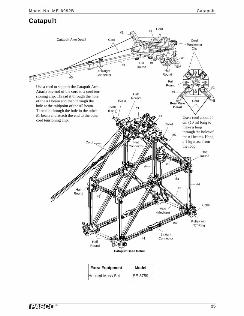
Catapult
#4
#Straight Connector
#5
Full Round
#1
#1
Half Round
#1 #1
Cord Tensioning
Clip
#1
Full Round
#1
Catapult Arm Detail
Rear View Detail
#1
Cord
Cord
Cord
Use a cord to support the Catapult Arm. Attach one end of the cord to a cord ten-sioning clip. Thread it through the hole of the #1 beam and then through the hole at the midpoint of the #5 beam. Thread it through the hole in the other #1 beam and attach the end to the other cord tensioning clip.
Axle (Long)
Collet
Half Round
Collet
Half Round
#5
#4
#4#5
#4
Collet
Pulley with “O” Ring
Flat Connector
#4
#1
Cord
Half Round
Half Round
Straight Connector#4
Catapult Base Detail
#3
Axle (Medium)
#3
Use a cord about 24 cm (10 in) long to make a loop through the holes of the #1 beams. Hang a 1 kg mass from the loop.
Extra Equipment Model
Hooked Mass Set SE-8759

�
Advanced Structures Set Catapul t
26 012-12719B
Catapult: Details
Operation
Hang a 1 kg mass from the loop of cord shown in the Rear View Detail.
Thread a piece of cord about 20 cm in length through a pulley and tie the cord so it makes a loop. Hang the loop at the end of the catapult arm.
Pull the catapult arm down so that the pulley/projectile is near the table top and the catapult arm is touching the front of the base.
Release the catapult arm to send the pulley/projectile on its way.
Question
What happens to the motion of the catapult as the 1-kg mass is allowed to drop?
The small tab at the end of the Catapult Arm
keeps the cord from falling off.
1-kg mass
� 27
Model No. ME-6992B Camelback Truss Br idge
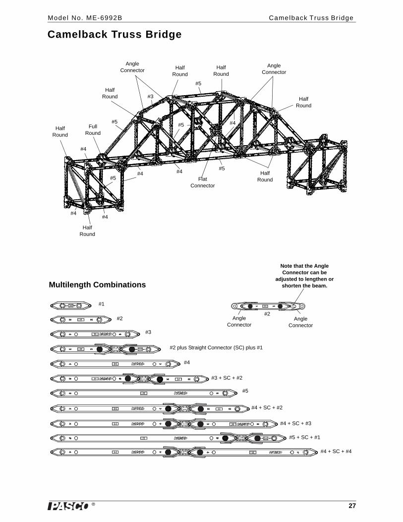
Camelback Truss Bridge
Half Round
Half Round
Half Round
Half Round
Half Round
Full Round
Half Round
Angle Connector
Angle Connector
#4#5
#4#4
#4
#5#5
#5
#3
#5#4
#4
Flat Connector
Half Round
Multilength Combinations
#1
#2
#3
#2 plus Straight Connector (SC) plus #1
#4
#3 + SC + #2
#5
#4 + SC + #2
#4 + SC + #3
#5 + SC + #1
#4 + SC + #4
#2Angle
ConnectorAngle
Connector
Note that the Angle Connector can be
adjusted to lengthen or shorten the beam.

�
Advanced Structures Set Truss Br idge wi th Cross Bracing
28 012-12719B
Truss Bridge with Cross Bracing
#5
#4
#3
2X3
Flat 4Flat 4
3X4
Half Round
#2
#3
#5
#3
#3
3X4
3X4
#3
Angle Connector
#3
Full Round
Angle Connector
#2
#5
#5
Angle Connector
#2
#3
#3
Half Round
Trestle with Cross Bracing
#5
#5
#4
#4
#4

� 29
Model No. ME-6992B PAStrack Trest le wi th Cross Bracing
PAStrack Trestle with Cross Bracing
PAStrack
#3
#3
2X3
#3
3X4
#3
Flat 4
Flat 4
#3
Half Round
#1
Angle Connector
Nut and Bolt for PAStrack
Flat Connector
Nut and Bolt
Flat Connector
Angle Connector
#1
PAStrack
Half Round
Half Round
�
Advanced Structures Set Tower wi th Cross Bracing
30 012-12719B
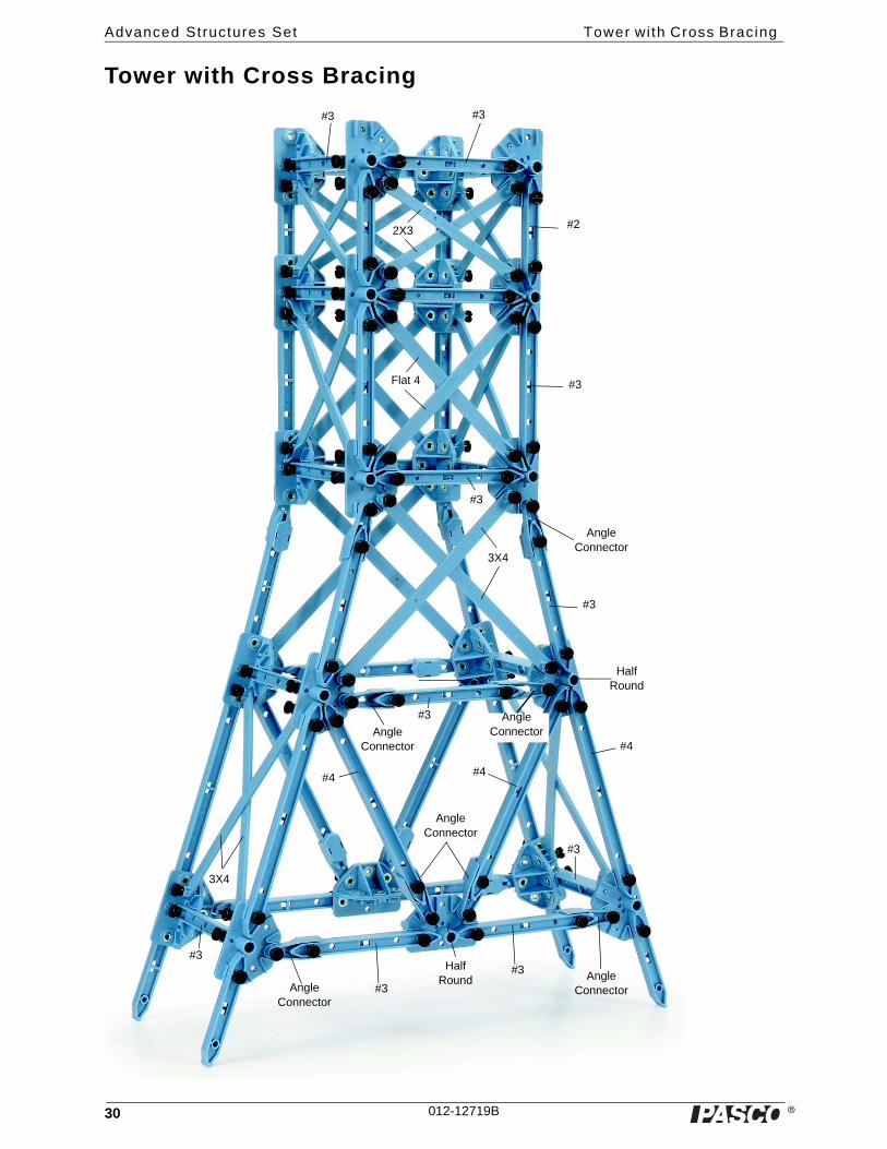
Tower with Cross Bracing
#3
#3
#2
#3
#4
#4#4
Angle Connector
#3
#3Angle Connector
Angle Connector
#3
#3
#3
Angle Connector
Angle Connector
Angle Connector
#3
3X4
3X4
Flat 4
2X3
Half Round
Half Round
#3

�
Model No. ME-6992B Rubber Band Powered “Car”
31012-12719B
Rubber Band Powered “Car”
The rubber band powered “car” uses a piece of rubber cord (sold separately, ME-8986 Rubber Cord) that stores elastic potential energy when the cord is stretched. When the car is released, the elastic potential energy becomes kinetic energy as the car moves.
Assemble the pieces of the car except for the Cord Tensioning Clip.
Get a piece of rubber cord about 2.5 m long and thread it through the Cord Tensioning Clip.
Pull the cord through the clip so that there are two ends of the same length.
Thread the two ends of the cord through a hole in the lower rear axle.
Loop the two rubber cords around the pulley on the front axle and then loop the cords around the pulley on the upper rear axle.
Finally, attach the Cord Tensioning Clip to the Sliding Connector.
Turn the Drive Wheel by hand to wind the rubber cord around the lower rear axle, or place the car on the floor and push it backwards so that the rubber cord winds around the lower rear axle.
Release the car in a clear area. The two ends of the rubber cord should come loose from the lower rear axle after the cord is unwound so the car can continue to roll.
Sliding Connector
Cord Tensioning
Clip
Rubber cord
#4
#4
#4#4
#5
#5
#3
#3
#3
#2
Straight Connector
Angle Connector
Angle Connector
#3
Axle
Axle
Axle
Pulley
Pulley
O-ringCollet
Tire
Drive Wheel
Half Round
Rubber cord
Inset Details
Inset
�
Advanced Structures Set Spares Part Numbers.
32 012-12719B
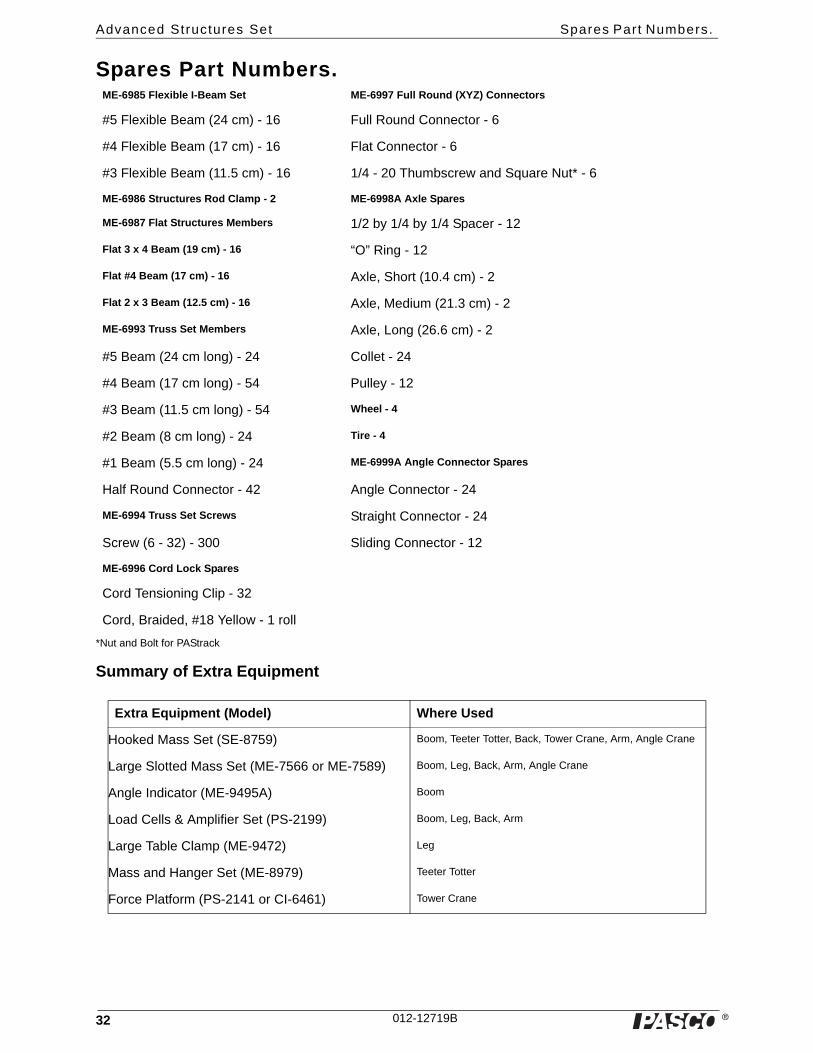
Spares Part Numbers.
*Nut and Bolt for PAStrack
Summary of Extra Equipment
ME-6985 Flexible I-Beam Set ME-6997 Full Round (XYZ) Connectors
#5 Flexible Beam (24 cm) - 16 Full Round Connector - 6
#4 Flexible Beam (17 cm) - 16 Flat Connector - 6
#3 Flexible Beam (11.5 cm) - 16 1/4 - 20 Thumbscrew and Square Nut* - 6
ME-6986 Structures Rod Clamp - 2 ME-6998A Axle Spares
ME-6987 Flat Structures Members 1/2 by 1/4 by 1/4 Spacer - 12
Flat 3 x 4 Beam (19 cm) - 16 “O” Ring - 12
Flat #4 Beam (17 cm) - 16 Axle, Short (10.4 cm) - 2
Flat 2 x 3 Beam (12.5 cm) - 16 Axle, Medium (21.3 cm) - 2
ME-6993 Truss Set Members Axle, Long (26.6 cm) - 2
#5 Beam (24 cm long) - 24 Collet - 24
#4 Beam (17 cm long) - 54 Pulley - 12
#3 Beam (11.5 cm long) - 54 Wheel - 4
#2 Beam (8 cm long) - 24 Tire - 4
#1 Beam (5.5 cm long) - 24 ME-6999A Angle Connector Spares
Half Round Connector - 42 Angle Connector - 24
ME-6994 Truss Set Screws Straight Connector - 24
Screw (6 - 32) - 300 Sliding Connector - 12
ME-6996 Cord Lock Spares
Cord Tensioning Clip - 32
Cord, Braided, #18 Yellow - 1 roll
Extra Equipment (Model) Where Used
Hooked Mass Set (SE-8759) Boom, Teeter Totter, Back, Tower Crane, Arm, Angle Crane
Large Slotted Mass Set (ME-7566 or ME-7589) Boom, Leg, Back, Arm, Angle Crane
Angle Indicator (ME-9495A) Boom
Load Cells & Amplifier Set (PS-2199) Boom, Leg, Back, Arm
Large Table Clamp (ME-9472) Leg
Mass and Hanger Set (ME-8979) Teeter Totter
Force Platform (PS-2141 or CI-6461) Tower Crane

�
Model No. ME-6992B Br idges That Require an Advanced Set and a Br idge Set
33012-12719B
Bridges That Require an Advanced Set and a Bridge Set
Note that the I-Beam Suspension Bridge and Arched Causeway Bridge can use the I-Beams sideways for the arched part of the bridge, or the Flexible I-Beams. (Since the I-Beams bend more in this orientation they form a curve. The I-Beams used in this manner will take a set and be permanently bent.).
The bridge models on this page feature a road bed and mini-car. These items are included in the ME-6991 Bridge Set and the ME-6995 Road Spares Set. (See the PASCO catalog or web site at www.pasco.com for more infor-mation.)
I-Beam Suspension Bridge
2.5 meter longCable Stayed Bridge
1.7 meter long
Arched Causeway Bridge
2.5 meter long
*Road Bed and Mini-car included in the ME-6991 Bridge Set.
34
Advanced Structures Set I -Beam Suspension Br idge Detai ls
�34
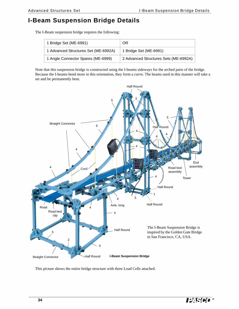
I-Beam Suspension Bridge Details
The I-Beam suspension bridge requires the following:
Note that this suspension bridge is constructed using the I-beams sideways for the arched parts of the bridge. Because the I-beams bend more in this orientation, they form a curve. The beams used in this manner will take a set and be permanently bent.
This picture shows the entire bridge structure with three Load Cells attached.
1 Bridge Set (ME-6991) OR
1 Advanced Structures Set (ME-6992A) 1 Bridge Set (ME-6991)
1 Angle Connector Spares (ME-6999) 2 Advanced Structures Sets (ME-6992A)
4
4
4
4
5
5
Half Round
Half Round
Straight Connector
Straight Connector
3
2
4
13
Half Round
Half Round
Half Round
4
4
Road bed assembly
Tower
Endassembly
5
44
4
Axle, long
4
3
Half Round
Cord
RoadRoad bed
clip
I-Beam Suspension Bridge
The I-Beam Suspension Bridge is inspired by the Golden Gate Bridge in San Francisco, CA, USA.
�
Model No. ME-6992B I-Beam Suspension Br idge End Assembly
35012-12719B
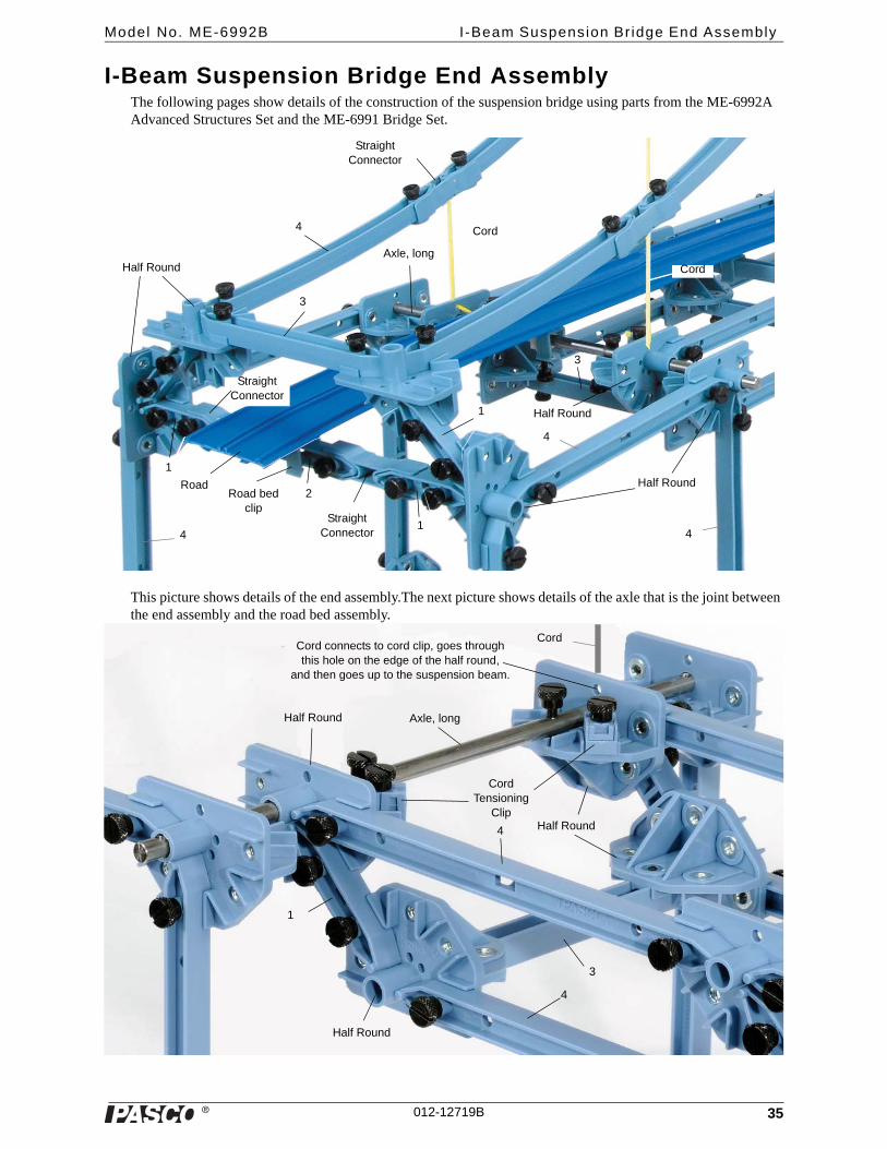
I-Beam Suspension Bridge End AssemblyThe following pages show details of the construction of the suspension bridge using parts from the ME-6992A Advanced Structures Set and the ME-6991 Bridge Set.
This picture shows details of the end assembly.The next picture shows details of the axle that is the joint between the end assembly and the road bed assembly.
Half Round
Half Round
Half Round
3
Axle, long
1
1Straight
Connector
2Road bed clip
Straight Connector
1
Road
4
44
4
Straight Connector
Cord
Cord
3
Axle, long
Cord Tensioning
ClipHalf Round
Half Round
Half Round
1
3
4
4
Cord connects to cord clip, goes through this hole on the edge of the half round,
and then goes up to the suspension beam.
Cord

36
Advanced Structures Set I -Beam Suspension Br idge Tower
�36
I-Beam Suspension Bridge Tower
The next picture shows details of the road bed assembly where it joins the first tower.
The next picture shows details of the top of the first tower. The suspensions beams are not shown.
I-Beam Suspension Bridge Road Bed Assembly
The middle section of the road bed assembly has eight #4 beams on the top of each side, and six #4 beams on the bottom of each side. The middle of the bottom part of the structure is joined by a #2 beam on both sides. The two
Half Round
Half Round
Half Round
Full RoundFull
Round
Full Round
Angle Connector
Angle Connector
1
1
3
4
44
4
4
4
2
3
1
4Middle section of road bed assembly connects here.
3
1
Half Round
Half Round

� 37
Model No. ME-6992B Flexib le I -Beam Suspension Br idge
sides are joined by #3 beams. The next picture shows details of one half of the middle section of the road bed assembly.
Flexible I-Beam Suspension Bridge
The following shows a suspension bridge model using Flexible I-Beams for the suspension beams instead of the hard plastic I-Beams.
Midpoint of middle section
2
24
4
Angle Connector
Tower connects to this full round
1
Half Round
1
Left half of middle section
Flexible I-Beam Suspension Bridge
#3 #2
#3
#2
#1
Flex 3
Flex 4
Flex 5Straight
Connector
Half Round
Full Round
#3
3 X 4
Flat 42 X 3
#4
#4
Angle Connector
#5
Flex 5
Flex 4 Flex 4
Cord Tensioning
Clip
CordSlotted masses
(not included)

�
Advanced Structures Set Flat Beam Suspension Br idge
38 012-12719B
Flat Beam Suspension Bridge
The following shows a suspension bridge model using Flat Members for the suspension beams instead of I-Beams.
Flat Members Suspension Bridge
#3
#2
#3
#2#1
Straight Connector
Half Round
Full Round
#3
2 X 3
2 X 3
#4
#4
Straight Connector
#5
Cord Tensioning
Clip
Straight Connector
#3#2
#3
#3
#2
Cord
*Road Bed and Mini-car included in the ME-6991 Bridge Set.

�
Model No. ME-6992B Cable Stayed Br idge
39012-12719B
Cable Stayed Bridge
The following pages show details of the Cable Stayed Bridge.
#4
#5
Angle Connector
Straight Connector
#5
#1
#2
Half Round
Straight Connector
#3
#2
#3
#3
#2
Straight Connector
#4
Half Round
Angle Connector
Angle Connector
#3
#2
#3#5
Angle Connector
#2
#2
#1
#1
#3
Axle
Axle
Use #2 beams as the cross pieces for the road bed.
Mini-car*
Road Bed*
*Road Bed and Mini-car not included.
�
Advanced Structures Set Cable Stayed Br idge
40 012-12719B
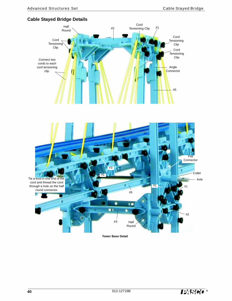
Cable Stayed Bridge Details
Half Round
#1
#2
#5
#2 #1
Angle Connector
Cord Tensioning
Clip
Cord Tensioning Clip
Cord Tensioning
Clip
Cord Tensioning
Clip
Connect two cords to each
cord tensioning clip.
#1
Axle
Collet
#5
Flat Connector
#3
#3
#1
Half Round
Tower Base Detail
Tie a knot in one end of the cord and thread the cord through a hole on the half
round connector.

�
Model No. ME-6992B Bal t imore Br idge
41012-12719B
Baltimore Bridge
Arched Causeway Bridge Detail 1
Baltimore Bridge
2.3 meter long
Baltimore Bridge: Details
#3
#4
#5
Half Round
Full Round
Flat Connector#5
#4
#3
#3#3
#4#4
#4
#4
#5
#3
#5
#3
Half Round
#3
#3
#3
#3
#1
#1
#1
Angle Connector
Angle Connector
Straight Connector
#1
#1
Cord Tensioning
Clip
�
Advanced Structures Set Arch Truss Br idge
42 012-12719B
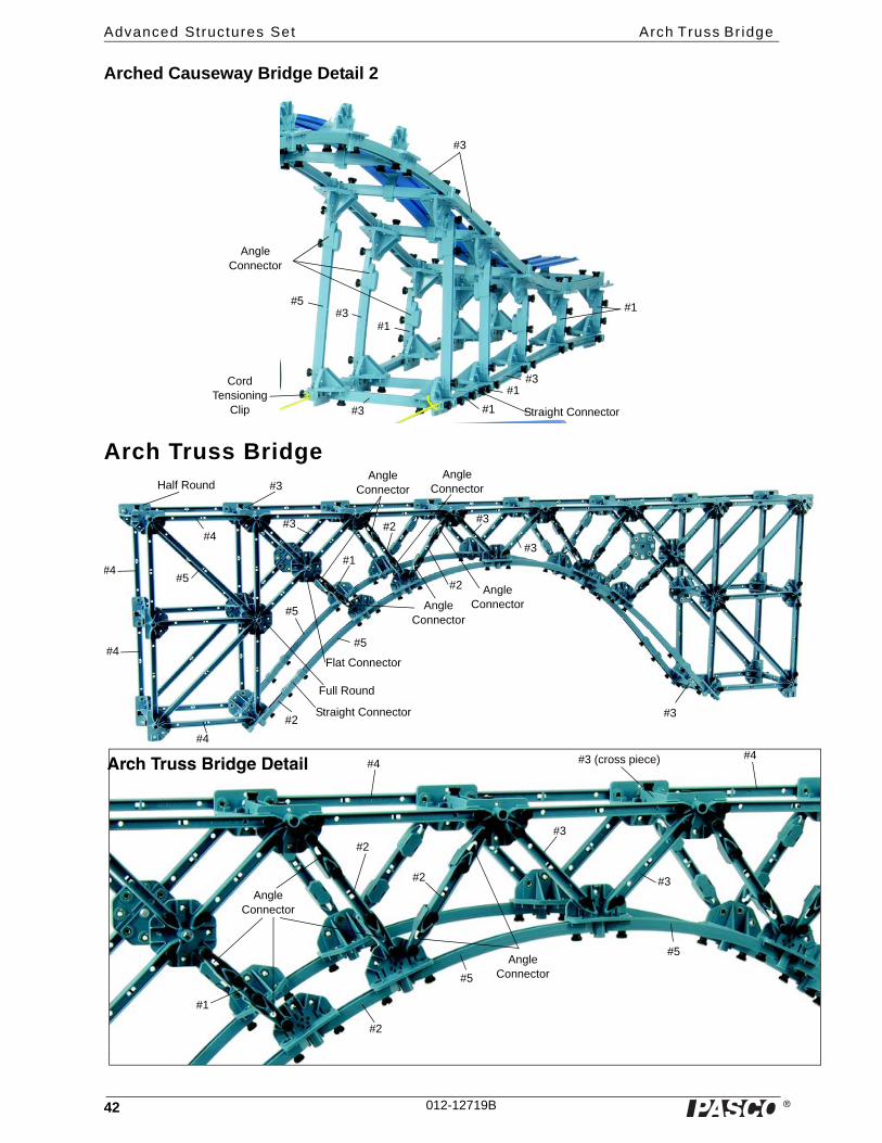
Arched Causeway Bridge Detail 2
Arch Truss Bridge
#3#5
#1
#3
#3
Angle Connector
#1
#1
#1 Straight Connector
#3
Cord Tensioning
Clip
#3
#2
#2
Angle ConnectorAngle
Connector
Angle Connector
#3
#3
Angle Connector#3
#5
#4
#4
#4
Full Round
#1
Flat Connector
Straight Connector#2
#5
#3
Half Round
Arch Truss Bridge Detail
#5
#3 (cross piece)
#4
#4
#3
#3
#2
Angle Connector
Angle Connector
#4
#5
#2
#2
#1
#5

�
Model No. ME-6992B Cant i levered Truss Br idge
43012-12719B
Cantilevered Truss Bridge
Use a Nut and Bolt for PAStrack to attach the PAStrack and PAStrack Curved sections to the members of the Advanced Structures Set. Slide the square nut into the “T-slot” on the side of the PAStrack and PAStrack Curved sections.
The PAStrack Cable Stayed Bridge shown on this page was constructed using components from two ME-6992A Advanced Structures Sets, four sets of PAStrack (ME-6960), and four sets of PAStrack Curved Sections (ME-6841).
#5Flat 4
#3
#4#3
#3
Cantilevered Truss Bridge Details
#3
Cross bracing 3X4#3
Angle Connector
Angle Connector
#4
#4
Cross bracing 2X3
Full Round
Half Round
Angle Connector#1
Cross bracing 2X3
Flat 4
#5
#5
#5Flat 4
#3
#3
#1
Angle Connector#3
#4Angle
Connector
Angle ConnectorStraight
Connector
#3
#2
#5
#4
#4
Straight Connector
Angle Connector
Angle Connector
Angle Connector
Angle Connector
Flat 4
Full Round
#4
#3
#3
#5 #5
#2
#3
2X3Half Round
Inset
Inset Details
� 44
Model No. ME-6992B Tied Arch Br idge wi th Cross Bracing
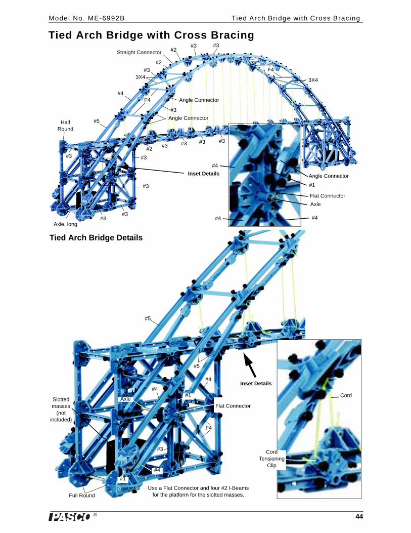
Tied Arch Bridge with Cross Bracing
#3
#3
#3#3
#3
Axle, long
#5
#4
#3
#2
#2Straight Connector#3
F4
3X4
#3
Angle Connector
Angle Connector
#3#3#3
#3
#2
Half Round
#3
Angle Connector
#1
Flat Connector
Axle
Inset Details
F4
3X4
#4
#4 #4
Tied Arch Bridge Details
#4
F4
#5
#5
#3
#4
#4
Full Round
AxleFlat Connector
#1 Cord
Inset Details
Cord Tensioning
Clip
#1
Slotted masses
(not included)
Use a Flat Connector and four #2 I-Beams for the platform for the slotted masses.
� 45
Model No. ME-6992B Double Tied Arch Br idge wi th Flexible I -Beams
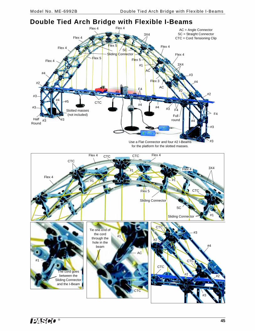
Double Tied Arch Bridge with Flexible I-Beams
#3#3
#5#4
F4
Use a Flat Connector and four #2 I-Beams for the platform for the slotted masses.
Half Round
#3
#2
#3
3X4
#3
#4
Flex 4
Flex 3
AC = Angle ConnectorSC = Straight Connector
CTC = Cord Tensioning Clip
AC
AC
#1
Flex 5
Sliding ConnectorSC
#4
#3
#3
#4
F4
F4
#4#3
3X4
Flex 4
#2
Full round
CTC
#2
#4
Flex 4
Flex 4
Flex 4
Flex 4
Flex 5
Flex 5
Flex 4
Slotted masses (not included)
Flex 4Flex 4
Flex 4
Flex 4 3X4
SC
Sliding Connector
Flex 5
#1
#1
#1
CTC
CTC
#2#2
#2
#3
#3
#1
CTC CTC
CTC
#4
CTC
CTC
#1
AC
CTC
Tie one end of the cord
through the hole in the
beam
The cord goes between the
Sliding Connector and the I-Beam
Sliding Connector
#1
46
Advanced Structures Set PAStrack Cable Stayed Br idge
�46
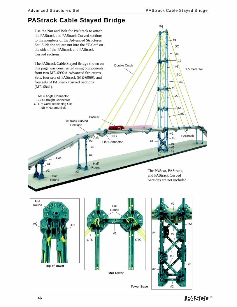
PAStrack Cable Stayed Bridge
1.5 meter tall
PAStrack Curved Sections
PAStrack
PAScar
The PAScar, PAStrack, and PAStrack Curved Sections are not included.
Use the Nut and Bolt for PAStrack to attach the PAStrack and PAStrack Curved sections to the members of the Advanced Structures Set. Slide the square nut into the “T-slot” on the side of the PAStrack and PAStrack Curved sections.
The PAStrack Cable Stayed Bridge shown on this page was constructed using components from two ME-6992A Advanced Structures Sets, four sets of PAStrack (ME-6960), and four sets of PAStrack Curved Sections (ME-6841).
#2
AC
AC = Angle ConnectorSC = Straight Connector
CTC = Cord Tensioning ClipNB = Nut and Bolt
Axle
#3
#4
#2
SC
Axle
Flat Connector
NB
#4
SC
#4
#4
SC
#4
#5
#5
#2
#2
#3
#3
#1
#4#4
#2
#3#2
#3
#3
#4
#4
#2
#2
#3
#2
#3
#2
Full Round
Full Round
ACAC
CTC CTC
#2
Half Round
Half Round
Top of Tower
Mid Tower
Tower Base
Double Cords
� 47
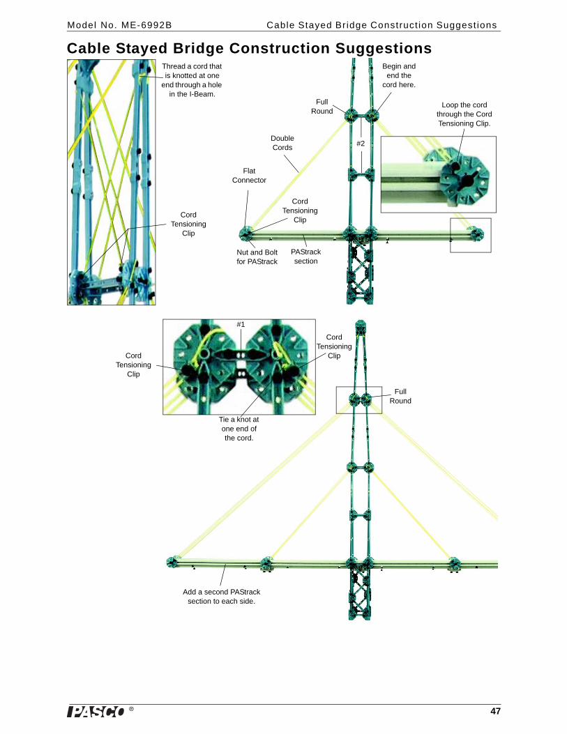
Model No. ME-6992B Cable Stayed Br idge Construct ion Suggest ions
Cable Stayed Bridge Construction SuggestionsThread a cord that is knotted at one
end through a hole in the I-Beam.
Cord Tensioning
Clip
Full Round
PAStrack section
Flat Connector
Nut and Bolt for PAStrack
Cord Tensioning
Clip
Begin and end the
cord here.
Loop the cord through the Cord Tensioning Clip.
#2
#1
Full Round
Add a second PAStrack section to each side.
Cord Tensioning
Clip
Tie a knot at one end of the cord.
Cord Tensioning
Clip
Double Cords
�
Advanced Structures Set Resonance Structures: Beam and Tower
48 012-12719B
Resonance Structures: Beam and Tower
The PASCO Structures System can be used to demonstrate resonance in complex structures. Resonance is the tendency of a structure to oscillate at a greater amplitude at some frequencies than at others. These are known as the structure’s resonance frequencies. At these frequencies, even small periodic driving forces can produce large amplitude oscillations.
Resonance occurs when a structure is able to store and transfer energy between two or more different storage modes (such as kinetic energy and potential energy in the case of a pendulum). However, there are some losses from cycle to cycle, called damping. When damping is small, the resonant frequency is approximately equal to the natural frequency of the structure, which is a frequency of unforced vibrations. Some structures have multi-ple, distinct, resonant frequencies.
Resonance phenomena occur with all types of vibrations or waves. The resonance structures demonstrate mechanical resonance. Unlike a standing wave on a string vibrating between two rods which has nodes at both ends, the resonance beam has a node at one end and an antinode at the other.
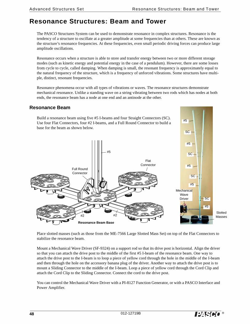
Resonance Beam
Build a resonance beam using five #5 I-beams and four Straight Connectors (SC). Use four Flat Connectors, four #2 I-beams, and a Full Round Connector to build a base for the beam as shown below.
Place slotted masses (such as those from the ME-7566 Large Slotted Mass Set) on top of the Flat Connectors to stabilize the resonance beam.
Mount a Mechanical Wave Driver (SF-9324) on a support rod so that its drive post is horizontal. Align the driver so that you can attach the drive post to the middle of the first #5 I-beam of the resonance beam. One way to attach the drive post to the I-beam is to loop a piece of yellow cord through the hole in the middle of the I-beam and then through the hole on the accessory banana plug of the driver. Another way to attach the drive post is to mount a Sliding Connector to the middle of the I-beam. Loop a piece of yellow cord through the Cord Clip and attach the Cord Clip to the Sliding Connector. Connect the cord to the drive post.
You can control the Mechanical Wave Driver with a PI-8127 Function Generator, or with a PASCO Interface and Power Amplifier.
#5
#5
#5
#5
#5
SC
SC
SC
SC
Mechanical Wave Driver
Resonance Beam Base
#5
#2#2
Flat Connector
Full Round Connector
Slotted Masses

�
Model No. ME-6992B Resonance Structures: Beam and Tower
49012-12719B
Resonance Tower
The Resonance Tower is a model of a building frame constructed with F4 Flat Members, #3 I-beams, #2 I-beams, Full Round Connectors, Half Round Connec-tors, and a Flat Connector.
As with the Resonance Beam, you can use the Mechani-cal Wave Driver controlled by a Function Generator to shake the building. In addition, you can use a 5 N Load Cell PS-2201 to measure the acceleration of the Reso-nance Tower and use a Motion Sensor to measure the amplitude of its movement.
Use four #2 I-beams and a Flat Connector (as shown) to build the support for the slotted masses at the ground floor of the structure.
Equipment Needed Part Number
Mechanical Wave Driver SF-9324
Function Generator PI-8127
Rod, 25 cm, threaded ME-8988
Small “A” Base ME-8976
Banana Plug Patch Cords SE-9750 or SE-9751
Resonance Tower Structure
F4F4
Half Round
#3
Full Round
Mechanical Wave Driver
Function Generator
Cord
Slotted Mass
Use foam core board or cardboard for the floors.
Cut a circle in the center of each floor large enough to fit the top of a slotted mass.
Place the slotted mass top down onto each floor.
Resonance Tower Base
#3
#3
#2 #2
Full Round
Flat Connector

�
Advanced Structures Set Resonance Structures: Beam and Tower
50 012-12719B
Measure Acceleration
To measure the acceleration of the Resonance Tower, replace one of the #3 I-beams at the top floor of the tower with a Half Round Connector and two #1 I-beams as shown. Connect the 5 N Load Cell to the tower with a #1 I-beam, and mount a 50 g mass on the Load Cell.
Measure Oscillations
To study damped oscillations, replace the top floor of the tower with a ‘pendulum’ as shown. When the pendulum is tied in place with cord and cannot swing, the tower’s oscillations persist. When the pendulum is allowed to swing, the oscillations are damped. Mount a Motion Sensor on a support rod to measure the oscillations.
50 g mass
#1
#1
Half Round
5N Load Cell
Measure Acceleration
Slotted mass
Motion Sensor
F4
#2
#2
Collet
Medium Axle
#3
Half Round
Flat Connector
50 g mass
Half Round
Cord Clip
Cord
Pendulum fixed
Pendulum swinging
Measure Oscillations

�
Model No. ME-6992B Force Plat form Structures Bracket (ME-6988A)
51012-12719B
Force Platform Structures Bracket (ME-6988A)
Introduction
The PASCO model ME-6992B Force Platform Structures Bracket includes two brackets and four thumbscrews. The adapter bracket is designed to connect members of the PASCO Structures System to a PASCO Force Platform.
Each Force Platform Structures Bracket has six positions where members of a PASCO Structure System can be attached, and two thumbscrews for attaching the bracket to a Force Platform. Note that each bracket also has two threaded holes for storing the thumbscrews when they are not in use.
Advanced Set (ME-6992A) - The largest set with pulleys, axles, and additional connectors that make possible bridges which have angles other than 45 and 90 degrees. This set can also be used to build suspension bridges, cranes, cars and catapults.
The Force Platform allows the student to measure tension and compression forces in trusses, bridges, roller coasters, or other structures assembled with the PASCO Structures System sets.
See the PASCO catalog or web site (www.PASCO.com) for more information about the PASCO Structures System.
Force Platform Model Number
PASPORT 1-Axis PS-2141
PASPORT 2-Axis PS-2142
ScienceWorkshop 1-Axis CI-6461
Recommended Equipment Model Number
PASCO Structures System see www.pasco.com
�
Advanced Structures Set Instal lat ion
52 012-12719B
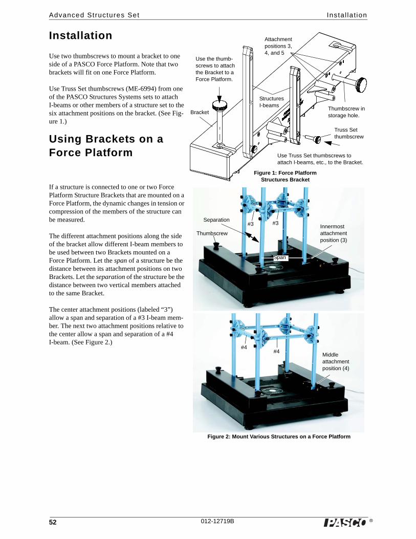
Installation
Use two thumbscrews to mount a bracket to one side of a PASCO Force Platform. Note that two brackets will fit on one Force Platform.
Use Truss Set thumbscrews (ME-6994) from one of the PASCO Structures Systems sets to attach I-beams or other members of a structure set to the six attachment positions on the bracket. (See Fig-ure 1.)
Using Brackets on a Force Platform
If a structure is connected to one or two Force Platform Structure Brackets that are mounted on a Force Platform, the dynamic changes in tension or compression of the members of the structure can be measured.
The different attachment positions along the side of the bracket allow different I-beam members to be used between two Brackets mounted on a Force Platform. Let the span of a structure be the distance between its attachment positions on two Brackets. Let the separation of the structure be the distance between two vertical members attached to the same Bracket.
The center attachment positions (labeled “3”) allow a span and separation of a #3 I-beam mem-ber. The next two attachment positions relative to the center allow a span and separation of a #4 I-beam. (See Figure 2.)
Use the thumb-screws to attach the Bracket to a Force Platform.
Thumbscrew in storage hole.
Use Truss Set thumbscrews to attach I-beams, etc., to the Bracket.
Truss Set thumbscrew
Figure 1: Force Platform Structures Bracket
Bracket
Structures I-beams
Attachment positions 3, 4, and 5
#3 #3Innermost attachment position (3)
Thumbscrew
Span
Separation
#4#4
Middle attachment position (4)
Figure 2: Mount Various Structures on a Force Platform

�
Model No. ME-6992B Other Uses for the Bracket
53012-12719B
The outermost attachment positions relative to the center are designed for a span of a #4 I-beam and a separation of a #5 I-beam if the Brackets are mounted on a PASCO Force Platform. However, if the Brackets are mounted on another platform, or no platform as shown in Figure 3, then the span can be longer or shorter than a #4 I-beam.
Please refer to the instruction manuals for the PASCO Structures System Sets for ideas of what structures can be built and attached to the Force Platform Structures Bracket and a Force Platform. Examples include large bridges and a tower crane.
Other Uses for the BracketYou can use the Force Platform Structures Bracket on a different force-measurement platform if you have the means to attach the Bracket to your platform.
As shown in Figure 4, it is also possible to attach a structure to just one Force Platform Structures Bracket.
The attachment positions on the Bracket are at the same height as the top attachment position on a “half-round” connector.
#5
Outermost attachment position (5)
#5
#4
#4
Half-round connector
#3
#3
Figure 4: Using one Force Platform Structures Bracket
Half-round connector
Innermost attachment position (3)
�
Advanced Structures Set Technical Support
54 012-12719B
Technical Support
For assistance with any PASCO product, contact PASCO at:
For more information about the Advanced Structures Set and the latest revision of this Instruction Manual, visit the PASCO web site at www.pasco.com and enter ME-6992B in the Search window.
Limited Warranty For a description of the product warranty, see the PASCO catalog.
Copyright The PASCO scientific 012-12179A Advanced Structures Set Instruction Manual is copyrighted with all rights reserved. Permission is granted to non-profit educational institutions for reproduction of any part of this manual, providing the reproductions are used only in their laboratories and classrooms, and are not sold for profit. Reproduction under any other circumstances, without the written consent of PASCO scientific, is prohibited.
Trademarks PASCO and PASCO scientific are trademarks or registered trademarks of PASCO scientific, in the United States and/or in other countries. All other brands, products, or service names are or may be trademarks or service marks of, and are used to iden-tify, products or services of, their respective owners. For more information visit www.pasco.com/legal.
Patents Pending: The following PASCO products are some of the products that have patents pending:
Address: PASCO scientific10101 Foothills Blvd.Roseville, CA 95747-7100
Phone: 916-786-3800 (worldwide)800-772-8700 (U.S.)
Fax: (916) 786-7565
Web: www.pasco.com
Email: [email protected]
ME-6990 Truss Set ME-6991 Bridge Set
ME-6992A Advanced Structures Set ME-6993 Truss Set Members
ME-6994 Truss Set Screws ME-6995 Road Bed Spares
ME-6996 Cord Lock Spares ME-6997 Full Round (XYZ) Connector Spares
ME-6998 Axle Spares ME-6999A Angle Connector Spares
PS-2198 Load Cell Amplifier PS-2199 Load Cell and Amplifier Set
PS-2200 100 N Load Cell PS-2201 5 N Load Cell
PS-2206 Dual Load Cell Amplifier