advanced server load-balancing deployment guide
TRANSCRIPT

Advanced Server Load-Balancing Deployment Guide
Revision: H1CY11

The Purpose of this Guide
The Purpose of this Guide
This guide is a concise reference on server load balancing.
This guide introduces the Cisco Application Control Engine (ACE, or ACE4710), the latest server load balancing offering from Cisco.
It explains the requirements that were considered when building the Cisco Smart Business Architecture design and introduces each of the products that were selected.
The final section of this guide will present the actual deployment steps that will get the product deployed and working in a specific environment.
Who Should Read This Guide
This guide is intended for the reader who has any or all of the following:
• Multipleapplicationservers
• Hoststheirownapplicationservers,eitherlocallyorco-located
• ITworkerswithaCCNA® certification or equivalent experience
• Islookingtodeployserverloadbalancing
• HasreadtheData Center Deployment Guide and wants more advanced features than are shown in the resilient server module
The reader may be looking for any or all of the following:
• Highavailabilityforapplications
• Scalinganapplicationacrossmultipleservers
• Theassuranceofatestedsolution
Related Documents
Before reading this guide
Data Center Design Overview
Data Center Deployment Guide
Data Center Configuration Files Guide
Advanced Server Load-Balancing
ConfigurationFiles
Design Overview
Design Guides Deployment Guides
You are HereData Center
Supplemental Guides

Table of Contents
ALLDESIGNS,SPECIFICATIONS,STATEMENTS,INFORMATION,ANDRECOMMENDATIONS(COLLECTIVELY,"DESIGNS")INTHISMANUALAREPRESENTED"ASIS,"WITHALLFAULTS.CISCOANDITSSUPPLIERSDISCLAIMALLWARRANTIES,INCLUDING,WITHOUTLIMITATION,THEWARRANTYOFMERCHANTABILITY,FITNESSFORAPARTICULARPURPOSEANDNONINFRINGEMENTORARISINGFROMACOURSEOFDEALING,USAGE,ORTRADEPRACTICE.INNOEVENTSHALLCISCOORITSSUPPLIERSBELIABLEFORANYINDIRECT,SPECIAL,CONSEQUENTIAL,ORINCIDENTALDAMAGES,INCLUDING,WITHOUTLIMITA-TION,LOSTPROFITSORLOSSORDAMAGETODATAARISINGOUTOFTHEUSEORINABILITYTOUSETHEDESIGNS,EVENIFCISCOORITSSUPPLIERSHAVEBEENADVISEDOFTHEPOSSIBILITYOFSUCHDAMAGES.THEDESIGNSARESUBJECTTOCHANGEWITHOUTNOTICE.USERSARESOLELYRESPONSIBLEFORTHEIRAPPLICATIONOFTHEDESIGNS.THEDESIGNSDONOTCONSTITUTETHETECHNICALOROTHERPROFESSIONALADVICEOFCISCO,ITSSUPPLIERSORPARTNERS.USERSSHOULDCONSULTTHEIROWNTECHNICALADVISORSBEFOREIMPLEMENTINGTHEDESIGNS.RESULTSMAYVARYDEPENDINGONFACTORSNOTTESTEDBYCISCO.
Any Internet Protocol (IP) addresses used in this document are not intended to be actual addresses. Any examples, command display output, and figures included in the document are shown for illustrative purposes only.AnyuseofactualIPaddressesinillustrativecontentisunintentionalandcoincidental.CiscoUnifiedCommunicationsSRND(BasedonCiscoUnifiedCommunicationsManager7.x)
© 2010 Cisco Systems, Inc. All rights reserved.
Table of Contents
Introduction . . . . . . . . . . . . . . . . . . . . . . . . . . . . . . . . . . . . . . . . . . . . . . . . . . . . . . . . . . . . . . . .1Guiding Principles . . . . . . . . . . . . . . . . . . . . . . . . . . . . . . . . . . . . . . . . . . . . . . . . . . . . . . 1
Business Overview . . . . . . . . . . . . . . . . . . . . . . . . . . . . . . . . . . . . . . . . . . . . . . . . . . . . . . . .2
Technology Overview . . . . . . . . . . . . . . . . . . . . . . . . . . . . . . . . . . . . . . . . . . . . . . . . . . . . .3Physical Topologies . . . . . . . . . . . . . . . . . . . . . . . . . . . . . . . . . . . . . . . . . . . . . . . . . . . . 4
ACE Overview . . . . . . . . . . . . . . . . . . . . . . . . . . . . . . . . . . . . . . . . . . . . . . . . . . . . . . . . . . 5
Deploying ACE . . . . . . . . . . . . . . . . . . . . . . . . . . . . . . . . . . . . . . . . . . . . . . . . . . . . . . . . . . . .10
Appendix A: ACE 4710 Configuration . . . . . . . . . . . . . . . . . . . . . . . . . . . . . . . . . . . 20
Appendix B: Glossary . . . . . . . . . . . . . . . . . . . . . . . . . . . . . . . . . . . . . . . . . . . . . . . . . . . 23
Appendix C: SBA for Midsize Organizations Document System . . . . . . . . . .24

1Introduction
SBA Overview
The Cisco® Smart Business Architecture (SBA) is a comprehensive design for networks with up to 2500 users. This out-of-the-box design is simple, fast, affordable, scalable, and flexible. There are three options based on your scaling needs: up to 600 users, 1000 users, and up to 2500 users.
TheCiscoSBAforMidsizeOrganizationsincorporatesLAN,WAN,wireless,security,WANoptimization,andunifiedcommunicationtechnologiestestedtogether as a solution. This solution-level approach simplifies the system integration normally associated with multiple technologies, allowing you toselectthemodulesthatsolveyourorganization’sproblemsratherthanworrying about the technical details.
WehavedesignedtheCiscoSmartBusinessArchitecturetobeeasytoconfigure, deploy, and manage. This architecture:
• Providesasolidnetworkfoundation
• Makesdeploymentfastandeasy
• Acceleratesabilitytoeasilydeployadditionalservices
• Avoidstheneedforre-engineeringofthecorenetwork
BydeployingtheCiscoSmartBusinessArchitecture,yourorganizationcangain:
• Astandardizeddesign,testedandsupportedbyCisco.
• Optimizedarchitecturesformidsizeorganizationswithupto2500users.
• WANwithupto75remotesiteswithaheadquarterssite,regionalsite,and approximately 25 users per remote site.
• Flexiblearchitecturetohelpensureeasymigrationastheorganizationgrows.
• Seamlesssupportforquickdeploymentofwiredandwirelessnetworkaccess for data, voice, teleworker, and wireless guest.
• Securityandhighavailabilityforcorporateinformationresources,servers, and Internet-facing applications.
• ImprovedWANperformanceandcostreductionthroughtheuseofWANoptimization.
• SimplifieddeploymentandoperationbyITworkerswithCCNA® certifica-tion or equivalent experience.
• Ciscoenterprise-classreliabilityinproductsdesignedformidsizeorganizations.
Guiding Principles
Wedividedthedeploymentprocessintomodulesaccordingtothefollowingprinciples:
• Ease of use: A top requirement of Cisco SBA was to develop a design that could be deployed with the minimal amount of configuration and day-two management.
• Cost-effective: Another critical requirement as we selected products wastomeetthebudgetguidelinesformidsizeorganizations.
• Flexibility and scalability: Astheorganizationgrows,sotoomustitsinfrastructure. Products selected must have the ability to grow or be repurposed within the architecture.
• Reuse: Westrived,whenpossible,toreusethesameproductsthroughoutthevariousmodulestominimizethenumberofproductsrequiredforspares.
UserServices
NetworkServices
NetworkFoundation
Voice,Video,
Web Meetings
Security, WAN Optimization,
Guest Access
Routing, Switching,Wireless, and Internet
The Cisco Smart Business Architecture can be broken down into the follow-ingthreeprimary,modularyetinterdependentcomponentsforthemidsizeorganization.
• Network Foundation: A network that supports the architecture
• Network Services: Features that operate in the background to improve and enable the user experience without direct user awareness
• User Services: Applications with which a user interacts directly

2Business Overview
Business Overview
The network is playing an increasingly important role in the success of an organization.KeyapplicationssuchasEnterpriseResourcePlanning(ERP),e-commerce, email, and portals must be available around the clock to provide uninterrupted business services. However, the availability of these applications is often threatened by network overloads as well as server and applicationfailures.Furthermore,resourceutilizationisoftenoutofbalance,resulting in the low-performance resources being overloaded with requests, while the high-performance resources remain idle. This is evidence that application performance, as well as availability, directly affects employee productivityandthebottomlineofanorganization.Asmoreusersworkmorehoursutilizingkeybusinessapplications,itbecomesevenmoreimportant to address application availability and performance issues to ensure achievement of business processes and objectives.
Manyfactorsmakeapplicationsdifficulttodeployanddelivereffectivelyover the network, including:
• Inflexible Application Infrastructure: Application design has historically been done on an application-by-application basis. This means that the infrastructure used for a particular application is often unique to that application. This type of design tightly couples the application to the infrastructure and offers little flexibility. Because the application and infrastructure are tightly coupled, it is difficult to partition resources and levels of control to match changing business requirements.
• Server Availability and Load: The mission-critical nature of applications puts a premium on server availability. Despite the benefits of server virtualizationtechnology,thenumberofphysicalserverscontinuestogrow based on new application deployments, raising power, and cooling requirements.
• Application Security and Compliance:Manyofthenewsecurityeventsare the result of application- and document-embedded attacks that compromise application performance and availability. Such attacks also potentially cause loss of vital application data—even while leaving networks and servers unaffected.
One way to improve application performance and availability is to rewrite theapplicationcompletelysoitisnetwork-optimized.However,thisrequiresapplication developers to have a much deeper understanding of how different applications respond to things like bandwidth constraints, delay, jitter, and other network variances. In addition, developers need a clearly predictableviewofanenduser’sforeseeableaccessmethod.Thisissimplynot feasible for every business application—particularly legacy applications thattookyearstowriteandcustomize.
Improvements to application performance begin in the data center. The Internet boom ushered in the era of the server load balancers, which balance the load on server banks to improve their response to client requests. Server load balancers have also evolved to take on additional responsibilities such as application proxies and complete Layer 4 through 7 application switching.

3Technology Overview
Technology Overview
The Application Control Engine (ACE, or ACE 4710) is the latest server load balancing (SLB) offering from Cisco. From its mainstream role in providing Layer 4 through 7 switching, Cisco ACE also provides an array of accelera-tion and server offload benefits, including:
• TransmissionControlProtocol(TCP)processingoffload
• SecureSocketLayer(SSL)offload
• Compression
• Variousotheraccelerationtechnologies
CiscoACEsitswithinthedatacenterinfrontoftheWebandapplicationserversandprovidesservicestomaximizeserverandapplicationavail-ability, security, and asymmetric (from server to client browser) application acceleration. As a result, Cisco ACE gives IT departments more control over application and server infrastructure, which enables them to manage and secure application services more easily and improves performance.
There are several ways to integrate ACE within the data center network as showninFigureSLBB-1.Logically,theACEisdeployedinfrontoftheWebapplication cluster. Requests to the application cluster are directed to a virtualIPaddress(VIP)configuredontheACE.TheACEreceivesconnec-tions and Hypertext Transfer Protocol (HTTP) requests and routes them to the appropriate application server based on configured policies as shown in Figure 2.
There are four key benefits provided by Cisco ACE:
• Scalability: ACE scales the performance of a server-based program, suchasaWebserver,bydistributingitsclientrequestsacrossmultipleservers, known as a server farm. As traffic increases, additional serv-erscanbeaddedtothefarm.Withtheadventofservervirtualization,applications can be staged and added dynamically as capacity require-ments change.
• High Availability (HA): ACE provides high availability by automatically detecting the failure of a server and repartitioning client traffic among the remaining servers within seconds, while providing users with continuous service.
Application Acceleration: ACE improves application performance and reducesresponsetimebyminimizinglatencyanddatatransfersforanyHTTP-based application, for any internal or external end user.
• Server Offload: ACE offloads TCP and SSL processing from the servers, allowing servers to serve more users and handle more requests without increasing the number of servers.
Figure 1. SLB Overview

4Technology Overview
Figure 2. Typical Load Balancing Traffic Flow Physical Topologies
Physically, the network topology can take many forms, including:
• OneArmedMode
• RoutedMode
• SingleVirtualLocalAreaNetwork(VLAN)One-ArmedMode
One-Armed Mode
One-ArmedModeisthesimplestdeploymentmethod,wheretheACEis connected off to the side of the Layer 2/Layer 3 infrastructure. It is not directly in the path of traffic flow and only receives traffic that is specifically intended for it. Traffic that should be directed to it is controlled by careful designofvirtualLANs(VLANs),virtualserveraddresses,serverdefaultgateway selection, or policy routes on the Layer 3 switch or upstream router.
Routed Mode
InRoutedMode,seeninFigure3,isthemostcommonlydeployedmethod.The load balancer acts as a Layer 3 device. It routes traffic flows between clientsandservers.Inthismode,therealserver’sdefaultgatewayistheloadbalancer.
Pros:
• Simpletopology,easeofconfigurationontheACE.
Cons:
• ACEdoesnotsupportanydynamicroutingprotocols.Staticroutesonly,leading to overhead.
• AllservertrafficmustpassthroughACE,whetherornotload-balancingisrequired.

5Technology Overview
Figure 3. RoutedMode
Single-VLAN One-Armed Mode
InSingle-VLANOne-ArmedMode,seeninFigure4,theloadbalancerresides on the same network as the real servers and clients. In this mode, therealserver’sdefaultgatewayistheupstreamrouter.Toensurethereturnflow traverses back through the load balancer, the IP address of the client is rewritten to that of the load balancer.
Pros:
• Layer2adjacencywiththerealserversisnotrequired.
• AbletopreserveclientsourceIPaddress.
• AllowsdirectservertraffictobypassACEwhenload-balancingisnotrequired.
Cons:
• ClientsourceIPaddressismaskedbyACEduetoSourceNAT.Allserv-ers see ACE as the client, resulting in loss of visibility of original client IP address.
• RequiresHTTPheaderinsertasaworkaroundtopreserveclientsourceIP address.
• Notsuitablefornon-HTTP-basedapplicationsthatrequiresourceIPaddress preservation.
Figure 4. Single-VLANOne-ArmedMode
ACE Overview
ACE hardware is always deployed in pairs for highest availability: One pri-mary and one secondary. If the primary ACE fails, the secondary ACE takes control. Depending on the configuration of session state redundancy, this failover may take place without disrupting the client-to-server connection.
Cisco ACE uses both active and passive techniques to monitor server health. By periodically probing servers, the ACE will rapidly detect server failures and quickly reroute connections to available servers. A variety of health-checkingfeaturesaresupported,includingtheabilitytoverifyWebservers, SSL servers, application servers, databases, File Transfer Protocol (FTP) servers, streaming media servers, and a host of others.

6Technology Overview
CiscoACEcanbeusedtopartitioncomponentsofasingleWebapplicationacrossseveralapplicationserverclusters.Forexample:ThetwoURLswww.mycompany.com/quotes/getquote.jsp and www.mycompany.com/trades/order.jsp could be located on two different server clusters even though the domain name is the same. This allows the application developer to easily scale the application to several servers without numerous code modifica-tions.Furthermore,itmaximizesthecachecoherencyoftheserversbykeeping requests for the same pages on the same servers.
Additionally, ACE may be used to push requests for cacheable content such as image files to a set of caches that can serve them more cost-effectively than the application servers.
RunningSSLontheWebapplicationserversisatremendousdrainonserverresources. By offloading SSL processing, those resources can be applied totraditionalWebapplicationfunctions.Inaddition,becausepersistenceinformation used by the content switches is inside the HTTP header, this information is no longer visible when carried inside SSL sessions. By termi-nating these sessions before applying content switching decisions, all the persistence options previously discussed become available for secure sites.
ACEreducestheamountofdatasentfromtheWebapplicationservertothebrowserbyutilizinghardwarecompressionandpatentedDeltaEncoding. Delta Encoding determines exactly what has changed from page to page, to the level of detail of a single byte, and sends only the content that has changed.
ACE further improves the end-user application experience by reducing latency and the number of roundtrips required for application access. ACE eliminates unnecessary browser cache validation requests and provides automatic embedded object version management at the server, resulting in significantly improved application response times for application users.
Virtualization
VirtualcontextsareseparatelogicalpartitionsthatessentiallyturnanACEappliance into multiple virtual instances that can be independently config-ured in terms of topology, resource usage, and functional usage.
Virtualcontextsshouldbecreatedonanas-neededbasis,usingthefollow-ing guidelines:
• ForApplicationTeamsthatrequirefrequentloginaccesstotheACEtoconfigure and/or fine-tune parameters, or to take real servers in and out of service, a separate context should be created on the basis of one context per Application Team to allow administrative segmentation. Each context can be tied to RBAC, with the appropriate users and roles assigned to each.
• Inmostcases,therewillbeadedicatedsetofapplicationdeliveryenvironments—Dev, Stage, Prod. If, however, this physical separation does not exist, then contexts should be created to segregate the differ-ent types of environments from each other.
• Tosupportvirtualcontexts,RBACneedstobeenabledonACE,withappropriate roles and domains defined and assigned to each user account.
• AllApplicationOwneraccessshouldbelimitedtotheirspecificvirtualcontext. They should not be allowed to view objects other than the ones permitted in their own virtual context. Cisco documentation on how to configure RBAC in ACE can be found online at http://www.cisco.com/en/US/docs/app_ntwk_services/data_center_app_services/ace_appliances/vA3_1_0/configuration/quick/guide/rbac.html
Hardware HA and Virtual Contexts
ACE hardware is always deployed in pairs: One primary appliance and one secondary appliance. It supports high availability using redundant Fault-Tolerant(FT)groupsthatareconfiguredbasedonvirtualcontexts.MultipleFT groups can be configured per ACE pair, but only one FT group can be associated with any virtual context pair. Two instances of the same context form a redundancy group, one is “Active” and the other “Standby”.
AFault-Tolerant(FT)VLANisadedicatedVLANusedbyaredundantACEpair to communicate heartbeat and state information. All redundancy-related trafficissentoverthisFTVLAN(includingTrustedRelayPoint(TRP)proto-col packets, heartbeats, configuration sync packets, and state replication packets).HeartbeatpacketsaresentoverUDPviatheFTVLANbetweenpeer units and are used to monitor the health of the peer device. The FT VLANalsocarriesstateinformationtransmittedbetweenthetwoACEpeersin order to maintain sessions and stickiness in the event of failover.
HAvirtualizationismodeledasfollows:
• Innormaloperationalstate:Allcontextsare“Active”ontheprimaryACEappliance, and all contexts are “Standby” on the secondary appliance.
• Inatransientfailurestate:Somecontextsare“Active”inoneACEappli-ance (A) and “Standby” in the other appliance (B), and other contexts are “Active” in (B) and “Standby” in (A).
• Eachcontextcanfailoverindependently.However,atanygiventime,eachcontextandeachVIPisactiveonlyononesinglephysicalACE.
• Preemptwithahigherpriorityshouldbeconfiguredinallvirtualcontextson the primary ACE appliance to force mastership after the primary appliance recovers from failure.

7Technology Overview
Load-Balancing
ACE traffic policies support the following SLB traffic attributes:
• Layer 3 and Layer 4 connection information: Source or destination Internet Protocol (IP) address, source or destination port, virtual IP address, and IP protocol. The ACE uses the Layer 3 and Layer 4 traffic classes to perform server load-balancing. For a Layer 3 and Layer 4 trafficclassification,thematchcriteriainaclassmapincludetheVIPaddress, protocol, and port of the ACE.
• Layer 7 protocol information:HTTPcookie,HTTPURL,HTTPheader,and SSL. The layer 7 SLB will have the same configuration logic of traffic class map and policy map, but its class map contains match criteria that classify specific Layer 7 network traffic. It is based on HTTP cookies, HTTPheaders,HTTPURLs,orSSLciphers.
The Load-Balancer gathers parse results from HTTP until HTTP is done parsingtheheader.Usingtheparseresults,ACEdeterminesthebestpolicymatch for load balancing.
Probe Functions
ACEletsyoucontinuallymonitortheserver’shealthandavailability.Itusesprobes as one of the available keep-alive methods to verify the availability of a real server. A probe can be attached to a real server, server farm, or a gateway. It can take a real server out of service for the following reasons:
• Probefailure
• ARPtimeout
• Noinservicecommand
• Inservicestandbycommand
Figure 5. Probe Functions
Probe Service Function
Dns Usesadefaultdomainof“www.cisco.com”
echo Configure echo probe
finger Configure finger probe
ftp Open a FTP connection with server and disconnect
http Sends a “GET / HTTP 1.1” request
https Establishes an SSL connection, send HTTP query and tears it down
icmp Configure icmp probe
imap Open an imap session and disconnect
ldap Configure ldap probe
pop3 Open a pop session and disconnect
radius Open an authentication session and disconnect
scripted UsesTCLInterpretertoexecuteuserdefinedTCLscripts and perform health monitoring
smtp Sendsa“hello”followedbya“QUIT”message
tcp Open a TCP session with server and disconnect withTCPFIN
telnet MakesaTelnetconnection,senda“QUIT”message
udp SendsaUDPpacket,probeisconsideredsuccess-ful if no icmp error is received
In addition to the default probe shown in Figure 5, ACE supports the usage of custom probes written in Tool Command Language (TCL) up to 256 script files. If the standard probes do not meet the requirements, application own-ers can provide a TCL probe for health monitoring.
Session Persistence
Session Persistence (or stickiness) is an ACE feature that allows the same client to maintain multiple simultaneous or subsequent TCP or IP connections with the same real server for the duration of a session. Load balancer accesses the sticky database before making a destination decision in case the connection already exists. If the ACE determines that a client is already stuck to a particular server, then the ACE sends that client request to that server, regardless of the load-balancing criteria specified by the matched policy.

8Technology Overview
Sticky code supports replication of the Sticky database for HA to other ACE appliances that have been configured in a Fault Tolerant group.
Supported sticky attributes include:
• IPaddress(source,destinationorboth)
• HTTPCookie:AcookieisasmalldatastructurewithintheHTTPheaderthatisusedbyaservertodeliverdatatoaWebclientandrequeststhatclient store the information. ACE can then use the information in the cookieorURLtodirectthecontentrequesttotheappropriateserver
• HTTPheader
• Configurationsynchronization
HA setup in ACE is on a per-context basis; therefore, the ACE configuration synchronizationisper-contextaswell.
There are two types of configuration sync, both of which will be needed:
• Bulksync,wheretheentireconfigurationistransferredfrom“Active”to“Standby”. Bulk sync is required when adding a new ACE peer to form a redundant pair.
• Dynamicsync,whereconfigurationchangesarecopiedtothe“Standby’context after it is reachable.
Incremental sync occurs after an ACE pair has been formed in steady state, andtheprimaryACEapplianceproactivelysynchronizeseachnewconfigu-ration change with the standby ACE.
Connection State Replication
Connection replication is supported with ACE while the switchover occurs between the HA pair. However, very short-term or proxy connections cannot be synced across. Persistent HTTP connections and other long-lived TCP connections will be replicated across the HA pair. This state replication trafficrunsovertheFTVLAN.
TCP Reuse
TCP reuse, also known as TCP multiplexing, is designed to improve applica-tion server performance by consolidating incoming TCP/IP requests to reduce the number of times server connections have to be made.
Figure 6. TCP Reuse
Configuration Rollback
ACE supports the creation of configuration snapshots so that the previous configuration can be rolled back in case mishaps happen during configura-tion changes.
Deep Packet Inspection
ACE performs application inspections of HTTP, File Transfer Protocol (FTP), DomainNameServer(DNS),InternetControlMessageProtocol(ICMP),and Real Time Streaming Protocol (RTSP) pro¬tocols as a first step before passing the packets to the destination server.
• HTTP: The ACE performs a stateful deep packet inspection of the HTTP protocol. During HTTP deep inspection, the main focus of the application inspection process is on HTTP attributes such as the HTTP header, the URL,and,toalimitedextent,thepayload.User-definedregularexpres-sions can also be used to detect “signatures” in the payload.
• FTP: FTP inspection inspects FTP sessions for address translation in a message, dynamic opening of ports, and stateful tracking of request and response messages. Each specified FTP command must be acknowl-edged before the ACE allows a new command. Command filtering allows youtorestrictspecificcommandsbytheACE.WhentheACEdeniesacommand, it closes the connection.

9Technology Overview
• DNS: DomainNameSystem(DNS)inspectionperformsthefollowingtasks:
– MonitorsthemessageexchangetoensurethattheIDoftheDNSresponsematchestheIDoftheDNSquery.o AllowsoneDNSresponseforeachDNSqueryinaUserDatagram
Protocol(UDP)connection.TheACEremovestheDNSsessionassociatedwiththeDNSqueryassoonastheDNSreplyisforwarded.
o TranslatestheDNSA-recordbasedontheNetworkAddressTranslation(NAT)configuration.OnlyforwardlookupsaretranslatedusingNAT;theACEdoesnothandlepointerrecords(PTR).
o Performs a number of security checks, including:
– Verifiesthatthemaximumlabellengthisnogreaterthan 63 bytes.
– Verifiesthatthemaximumdomainnamelengthisnogreater than 255 bytes.
– Checks for the existence of compression loops.
• ICMP: AllowsICMPtraffictohavea“session”sothatitcanbeinspectedsimilarlytoTCPandUDPtraffic.IfyoudonotuseICMPinspection,werecommendthatyounotcreateanACLthatallowsICMPtraffictopassthroughtheACE.Withoutstatefulinspection,ICMPcanbeusedtoattackyournetwork.ICMPinspectionensuresthatthereisonlyoneresponsefor each request, and that the sequence number is correct.
• RTSP: The Real Time Streaming Protocol (RTSP) is used by RealAudio, RealNetworks,AppleQuickTime4,RealPlayer,andCiscoIP/TVconnec-tions.RTSPapplicationsusethewell-knownport554withTCPandUDPas the control channel. The ACE supports TCP only in conformity with RFC 2326.
Application Acceleration
Usedtoincreasetheperformanceofdatacenter-basedWebapplications,the Cisco ACE 4710 uses asymmetric compression, FlashForward, and other patented techniques to reduce the volume of transferred data and improve response times to end users, thus providing a better overall end-user experience.
• Delta Optimization: Allows the ACE to enable the content provider to dynamically calculate the content differences, or deltas, between subsequent content retrievals (on a per-user basis if desired) and send only those deltas for subsequent visits to the dynamic content. A user wouldretrieve70KBonthefirstvisittothehomepagebutwouldneedtoretrieveonlythe2KBcontentdeltaonsubsequentvisits.Withdeltaoptimization,onlythedeltasbetweenthesubsequentlyrequestedpagesare sent to the users. These deltas, which are encoded by using dynamic HTML,enabletheACEtodirectlyupdatetheclient’sbrowsercache,much like an origin server updates a traditional edge cache.
• FlashForward Object Acceleration: Eliminates the network delays associatedwithembeddedWebobjectssuchasimages,stylesheets,andJavaScriptfiles.WithouttheACE,theuserexperiencesdelayswhenpages with graphic images load because each object requires valida-tion to ensure that the user has the latest version. Object validation can resultin20KBormoreofunnecessaryupstreamtraffic.Eachvalidationinvolves an HTTP request from the client to the server. FlashForward enforces embedded object version management at the server. All object validityinformationiscarriedinthesingledownloadoftheparentHTMLdocument, which eliminates unnecessary validation requests.

10Deploying ACE
Deploying ACE
Thefollowingcasestudy,whichexplainstheACMECompany’scurrentchallenges and setup, will be used to illustrate how to deploy ACE. The setup ishostedoffsitefromtheorganizationheadquartersatacollocationfacility.IPaddressesandnetworklayoutsdonotmatcheithertheSBAforMidsizeBorderlessNetworksdesignortheSBAMidsizeDataCenterdesignandaremeanttoshowatypicalexampleforamidsizeorganization.
ACME Company Overview
ACMECompanyisdeployinganewe-commercewebsitetoallowcustom-erstobrowseproductsandplaceordersonline.TheunderlyingWebapplicationutilizesa3-tierarchitecturewithApacheWebServerservingstatic content, Tomcat Application Server serving the dynamic content, and MySQLdatabaseserverforcustomerandproductinformationstorageandretrieval.
To ensure the e-commerce website is available around the clock, a pair of ACE 4710 load balancers will be deployed along with 2 Apache servers, 3 Tomcatservers,andaMySQLclusterasshowninFigure7.ACME’scus-tomers will access the new website through http://www.acme.com, which pointstoaVIPonapairofACE4710s.DependingontheactualWebpageor object being requested, the traffic will be forwarded to one of the two ApacheWebServersoroneofthethreeTomcatApplicationServers.TheTomcatserverscommunicatedirectlywiththeMySQLclusterforinformationstorage and retrieval.
Figure 7. E-CommerceWebApplicationNetworkLayout
For maximum network security, the servers will reside on a separate network with private IP addresses. ACE 4710 will be deployed in “routed” mode and serveasthedefaultgatewayfortheservers.OnlytheVIPontheACEwillbeexposed to the Internet.
TheApacheWebServershavebeenconfiguredtorunonTCPport80andserve static files under directories/images, /css, and /js. A static mainte-nancepagealsoresidesontheApacheWebServerunder/sry.html.Thispage will inform users that the site is undergoing maintenance when three of the Tomcat Application Servers are unavailable.
The Tomcat Application Servers have been configured to run on TCP port 8080andservedynamicallygeneratedfilesthatarenotservedbytheApacheWebServers.TheapplicationserversuseHTTPsessionstomain-tainstateinformationasausernavigatesACME’se-commercewebsite.ThissessionallowstheWebapplicationto“personalize”theuserexperiencebykeeping track of the individual users during the course of navigation, includ-ing any transactions. Therefore, ACE 4710 will be configured with session persistence to ensure that each user is returned to the Tomcat Application Server where their session resides.
To provide secure shopping sessions, a SSL certificate has been purchased for www.acme.com and will be installed on the ACE 4710 for encryption and decryption of the secure traffic. All requests to /cart need to be SSL-encrypted. Should a user issue nonencrypted requests to /cart, those requests are redirected so that they are encrypted.

11Deploying ACE
AsummaryoftheACMEE-CommerceapplicationenvironmentisshowninFigure8.
Figure8.ACMEE-CommerceWebsiteApplicationSummary
FullyQualifiedDomainName www.acme.com
VirtualIPAddress: 69.36.241.10
Protocols HTTP & HTTPS
ClientVLAN 10
ServerVLAN 100
ACE default gateway 69.36.241.1
ACE4710(Primary)VLAN10ipaddress 69.36.241.4
ACE4710(Secondary)VLAN10ipaddress 69.36.241.5
ACE4710(Primary)VLAN100ipaddress 192.168.100.2
ACE4710(Secondary)VLAN100ipaddress 192.168.100.3
Server default gateway 192.168.100.1
URI Path Served ByAdditional Settings
/images
/css
/js
/sry.html
ApacheWebServers
apache1(192.168.100.11:80)
apache2(192.168.100.12:80)
/cart Tomcat Application Servers NoHTTPtrafficallowed, HTTPS only
/* (everything else) Tomcat Application Servers
tomcat1 (192.168.100.21:8080)
tomcat2 (192.168.100.22:8080)
tomcat3 (192.168.100.23:8080)
Sorry Server Page (http:// www.acme.com/sry.html)
Session Persistence
Process
ConfiguringtheNetwork
1. DefinetheVirtualContext
2. Add a Health Probe
3. Configure the Real Server
4. Configure the Server Farm
5. Configure Session Persistence (Stickiness)
6. ConfiguretheVirtualServer
7. Configure SSL (HTTPS)
This process will explain how to set up a pair of ACE 4710s in order to provide load balancing for the application environment described in the above scenario.
Tech Ti p
These instructions do not cover the initial setup and configuration of ACE 4710. For basic setup instructions, please refer to the Smart Business Architecture Data Center Deployment Guide.

12Deploying ACE
Procedure 1 Define the Virtual Context
TheconfigurationfortheACMEe-commercewebsitewillbecontainedwithinaseparatevirtualizedcontextontheACE4710.
Step 1: Go to Config > Virtual Contexts, and click [+] to add a new virtual context. See Figure 9.
Figure 9. NewVirtualContext
Step 2:UnderNetwork > VLAN Interfaces, double click on the interface for ClientVLAN(VLAN10)toedittheVLANInterfaceandaddtheIPaddressforthe secondary ACE 4710 in the Peer IP Address dialog box. See Figure 10.
Figure 10. EditVLANInterfaces
Step 3:Next,underNetwork > VLAN Interfaces, click [+] to add a new VLANInterfacefortheServerVLAN,asshowninFigure11.
Figure 11. NewVLANInterface
Procedure 2 Add a Health Probe
Step 1: UnderLoad Balancing > Health Monitoring, click [+] to add a new healthprobetoperformabasicHTTPhealthcheck.We’lladdthishealthprobe when creating Server Farms, as shown in Figure 12.
Figure 12. NewHealthMonitoring

13Deploying ACE
Step 2: After a probe has been created, select the Expect Status tab at the bottom of the page, and enter the value 200forbothMaxandMinExpectedStatus Code, as shown in Figure 13.
Figure 13. Expect Status Tab
Procedure 3 Configure the Real Server
Step 1: UnderLoad Balancing > Real Servers, add 2 real servers for ApacheWebServers,namedapache1 and apache2, as shown in Figure 14.
Figure 14. NewRealServer
Step 2:Under Load Balancing > Real Servers, add 3 real servers for Tomcat Application Servers, named tomcat1, tomcat2, and tomcat3, as shown in Figure 15.
Figure 15. NewRealServer
Step 3:UnderLoad Balancing > Real Servers, add a redirect real server called maintenance_page for the maintenance page redirection, as shown in Figure 16.
Figure 16. Redirection for Application Failure

14Deploying ACE
Step 4: UnderLoad Balancing > Real Servers, add a redirect real server called https_redirect for redirecting users from cleartext (HTTP) to encrypted sessions (HTTPS) , as shown in Figure 17.
Figure 17. SSL Redirect
AsummaryofalltherealserverscreatedfortheACMEe-commerceweb-siteisshowninFigure18.
Figure18.Real Server Summary
Procedure 4 Configure the Server Farm
Step 1:UnderLoad Balancing > Server Farms, add a server farm called apache_farm togrouptherealserversfortheApacheWebServers,asshown in Figure 19.
Step 2: The http_probe help probe created earlier should appear under the Availablecolumn.MovetheprobetotheSelectedcolumnbyhighlightingitand clicking on the right arrow.
Step 3:Next,addapache1 and apache2 to the apache_farm server farm.
Figure 19. NewServerFarm

15Deploying ACE
Step 4:UnderLoad Balancing > Server Farms, add a server farm called tomcat_farm to group the real servers for the Tomcat Application Servers, asshowninFigure20.Next,addtomcat1, tomcat2, and tomcat3 to the tomcat_farm server farm.
Figure 20. Edit Server Farm
Step 5: UnderLoad Balancing > Server Farms, add a redirect server farm called maintenance_farm to group the real server for the maintenance page.
Step 6: Add the maintenance_page real server to the maintenance_farm server farm, as shown in Figure 21.
Figure 21. Edit Server Farm
Step 7: UnderLoad Balancing > Server Farms, add a redirect server farm called HTTPS_redirect_farm to group the real server for the HTTP to HTTPS redirection.
Step 8: Then add the https_redirect real server to the HTTPS_redirect_farm server farm, as shown in Figure 22.
Figure 22. Edit Server Farm
AsummaryofalltheserverfarmscreatedfortheACMEe-commercewebsite is shown in Figure 23.
Figure 23. Summary of Server Farms
16Deploying ACE
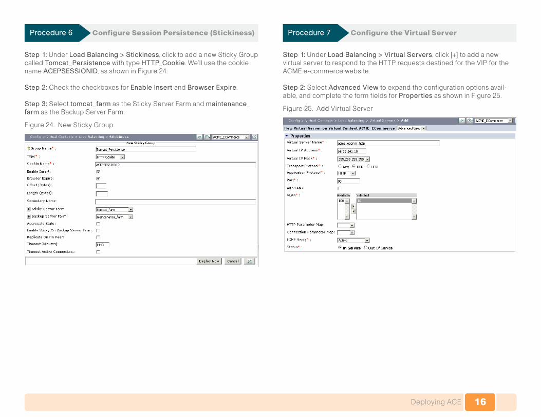
Procedure 6 Configure Session Persistence (Stickiness)
Step 1:UnderLoad Balancing > Stickiness, click to add a new Sticky Group called Tomcat_Persistence with type HTTP_Cookie.We’llusethecookiename ACEPSESSIONID, as shown in Figure 24.
Step 2: Check the checkboxes for Enable Insert and Browser Expire.
Step 3: Select tomcat_farm as the Sticky Server Farm and maintenance_farm as the Backup Server Farm.
Figure 24. NewStickyGroup
Procedure 7 Configure the Virtual Server
Step 1:UnderLoad Balancing > Virtual Servers, click [+] to add a new virtualservertorespondtotheHTTPrequestsdestinedfortheVIPfortheACMEe-commercewebsite.
Step 2: Select Advanced View to expand the configuration options avail-able, and complete the form fields for Properties as shown in Figure 25.
Figure 25. AddVirtualServer

17Deploying ACE
Step 3:UnderL7 Load-Balancing, create a new rule called static_files_objects to match requests for static files that are served from the Apache WebServers.SettheActiontoloadbalancetraffictotheapache_farm server farm, as shown in Figure 27.
Figure 26. L7 Load Balancing
Step 4: UnderL7 Load-Balancing, create a new rule called https_redirect to match requests for the secure page that should always be encrypted (HTTPS) , as shown in Figure 27.
Step 5: Set the Action to load balance traffic to the HTTPS_redirect_farm server farm.
Figure 27. L7 Load Balancing
Step 6: UnderDefault L7 Load-Balancing Action, set the Action to use Sticky with the Tomcat_PersistenceStickyGroup,asshowninFigure28.
Step 7: Select DeflateastheCompressionMethod.
Step 8:UnderApplication Acceleration and Optimization, select EZ, and check Latency Optimization (FlashForward).
Figure28.Default L7 Load Balancing Actions

18Deploying ACE
Procedure 8 Configure SSL (HTTPS)
This section guides you through the configuration of SSL termination with the existing SSL private key and certificate.
Step 1: UnderSSL > Setup Sequence, import the SSL private key by copy-ingandpastingthePEM-encodedkeyintotheImport Text form field under TERMINALProtocol,asshowninFigure29.
Figure 29. Startup Sequence
The imported key is listed under SSL > Keys as shown in Figure 30.
Figure 30. Keys
Step 2:UnderSSL > Setup Sequence, import the SSL certificate by copyingandpastingthePEM-encodedcertificateintoImportTextformfieldunderTERMINALProtocol,asshowninFigure31.
Figure 31. Startup Sequence
The imported key is listed under SSL > Certificates as shown in Figure 32.
Figure 32. Certificates
Step 3: UnderSSL > Proxy Service, click to add a new Proxy Service called acme_ ecomm_ssl to associate the imported private key and certificate, as shown in Figure 33.
Figure 33. NewProxyService

19Deploying ACE
Step 4: UnderLoad Balancing > Virtual Servers, click to add a new virtual servertorespondtotheHTTPSrequestsdestinedfortheVIPfortheACMEe-commerce website.
Step 5: SelectAdvancedViewtoexpandtheconfigurationoptionsavailable,and complete the form fields for Properties as shown in the picture below.
Step 6: UnderSSL Termination, select the acme_ecomm_ssl Proxy Service, as shown in Figure 34.
Figure 34. Properties
Step 7:UnderL7 Load-Balancing, select the static_files_objects rule for static filesthatareservedfromtheApacheWebServers,asshowninFigure35.
Step 8: Set the Action to load balance traffic to the apache_farm server farm.
Figure 35. StaticFileLoadBalancingforWebService
Step 9: UnderDefault L7 Load-Balancing Action, set the Action to use Sticky with the Tomcat_Persistence Sticky Group. Select Deflate as the CompressionMethod,asshowninFigure36.
Step 10: UnderApplication Acceleration and Optimization, select EZ, and check Latency Optimization (FlashForward).
Figure 36. Default L7 Load Balancing Action

20Appendix A
Appendix A: ACE 4710 Configuration
crypto csr-params acme_ecomm.csr country US state CA common-name www.acme.com
probe http HTTP_Head_Probe description Basic HTTP Probe that checks / returns 200 OK port 80 interval 15 passdetect interval 60 request method head open 1
parameter-map type http cisco_avs_parametermap case-insensitive persistence-rebalance
rserver host apache1 description Apache Web Server ip address 192.168.100.11 inservice rserver host apache2 description Apache Web Server ip address 192.168.100.12 inservice rserver redirect force_https description Redirect traffic to HTTPS webhost-redirection https://%h%p 302 inservice rserver redirect maintenance_page description Maintenance page displayed when all Tomcat servers fail webhost-redirection /sry.html 302 inservice rserver host tomcat1 description Tomcat Application Server ip address 192.168.100.21 inservice
rserver host tomcat2 description Tomcat Application Server ip address 192.168.100.22 inservice rserver host tomcat3 description Tomcat Application Server ip address 192.168.100.23 inservice action-list type optimization http cisco_avs_container_latency flashforward action-list type optimization http cisco_avs_img_latency flashforward-object action-list type optimization http cisco_avs_obj_latency flashforward-object
serverfarm redirect HTTPS_redirect_farm description Redirect traffic to HTTPS rserver force_https inservice serverfarm host apache_farm description Apache Web Server Farm probe HTTP_Head_Probe rserver apache1 80 inservice rserver apache2 80 inservice serverfarm redirect maintenance_farm description Send users to maintenance page rserver maintenance_page inservice serverfarm host tomcat_farm description Tomcat Application Server Farm probe HTTP_Head_Probe rserver tomcat1 8080 inservice rserver tomcat2 8080 inservice rserver tomcat3 8080 inservice
ssl-proxy service acme_ecomm_ssl key acme_ecomm.key cert acme_ecomm.crt
sticky http-cookie ACEPSESSIONID Tomcat_Persistence cookie insert browser-expire serverfarm tomcat_farm backup maintenance_farm

21Appendix A
class-map match-all acme_ecomm_http 2 match virtual-address 69.36.241.10 tcp eq www class-map match-all acme_ecomm_https 2 match virtual-address 69.36.241.10 tcp eq https class-map type http loadbalance match-all cisco_avs_container_latency 2 match http url .* class-map type http loadbalance match-any cisco_avs_img_latency 2 match http url .*jpg 3 match http url .*jpeg 4 match http url .*jpe 5 match http url .*png class-map type http loadbalance match-any cisco_avs_obj_latency 2 match http url .*gif 3 match http url .*css 4 match http url .*js 5 match http url .*class 6 match http url .*jar 7 match http url .*cab 8 match http url .*txt 9 match http url .*ps 10 match http url .*vbs 11 match http url .*xsl 12 match http url .*xml 13 match http url .*pdf 14 match http url .*swf class-map type http loadbalance match-any default-compression-exclusion-mime-type description DM generated classmap for default LB compression exclusion mime types. 2 match http url .*gif 3 match http url .*css 4 match http url .*js 5 match http url .*class 6 match http url .*jar 7 match http url .*cab 8 match http url .*txt 9 match http url .*ps 10 match http url .*vbs 11 match http url .*xsl 12 match http url .*xml 13 match http url .*pdf 14 match http url .*swf 15 match http url .*jpg 16 match http url .*jpeg 17 match http url .*jpe
18 match http url .*png class-map type http loadbalance match-any https_redirect 2 match http url /cart/.* class-map type management match-any mgmt 201 match protocol snmp any 202 match protocol xml-https any 203 match protocol telnet any 204 match protocol ssh any 205 match protocol kalap-udp any 206 match protocol icmp any 207 match protocol https any 208 match protocol http any class-map type http loadbalance match-any static_files_objects 2 match http url /images/.* 3 match http url /css/.* 4 match http url /js/.* 5 match http url /sry.html
policy-map type management first-match mgmt class mgmt permit
policy-map type loadbalance first-match acme_ecomm_http-l7slb class default-compression-exclusion-mime-type sticky-serverfarm Tomcat_Persistence class static_files_objects serverfarm apache_farm class https_redirect serverfarm HTTPS_redirect_farm class class-default compress default-method deflate sticky-serverfarm Tomcat_Persistence policy-map type loadbalance first-match acme_ecomm_https-l7slb class default-compression-exclusion-mime-type sticky-serverfarm Tomcat_Persistence class static_files_objects serverfarm apache_farm class class-default compress default-method deflate sticky-serverfarm Tomcat_Persistence policy-map type optimization http first-match acme_ecomm_http-l7opt class cisco_avs_obj_latency action cisco_avs_obj_latency class cisco_avs_img_latency action cisco_avs_img_latency class cisco_avs_container_latency action cisco_avs_container_latency

22Appendix A
policy-map type optimization http first-match acme_ecomm_https-l7opt class cisco_avs_obj_latency action cisco_avs_obj_latency class cisco_avs_img_latency action cisco_avs_img_latency class cisco_avs_container_latency action cisco_avs_container_latencypolicy-map multi-match int10 class acme_ecomm_http loadbalance vip inservice loadbalance policy acme_ecomm_http-l7slb optimize http policy acme_ecomm_http-l7opt loadbalance vip icmp-reply active appl-parameter http advanced-options cisco_avs_parametermap class acme_ecomm_https loadbalance vip inservice loadbalance policy acme_ecomm_https-l7slb optimize http policy acme_ecomm_https-l7opt loadbalance vip icmp-reply active appl-parameter http advanced-options cisco_avs_parametermap ssl-proxy server acme_ecomm_ssl
interface vlan 10 description “Client VLAN” ip address 69.36.241.4 255.255.255.240 peer ip address 69.36.241.5 255.255.255.240 service-policy input mgmt service-policy input int10 no shutdown interface vlan 100 description “Server VLAN” ip address 192.168.100.2 255.255.255.0 alias 192.168.100.1 255.255.255.0 peer ip address 192.168.100.3 255.255.255.0 no shutdown
ip route 0.0.0.0 0.0.0.0 69.36.241.1

23Appendix B
Appendix B: Glossary
This section provides a quick overview of the terminologies commonly used when working with application servers and server load balancers.
Real Server
Real servers are Application Servers. They usually sit behind a server load-balancer. In a typical network, there would be one or more real servers running the same application instance to service clients/users. Load balanc-ers allow administrators to add or remove real servers from the available pool without impacting service availability.
Virtual Server
Virtualserverrepresentsthelogicalinstanceoftheapplicationresidingon the load balancer, which in turn is mapped to a pool of real servers that actually provide content and application services. There can be one or more virtual server instances defined on the load balancer. Clients connect to the virtual server IP address assigned to the load balancer, and the load balancer distributes these requests among multiple real servers.
Health Probe
Health probe is a mechanism by which the hardware load balancer verifies that an application instance or the server is capable of delivering appropri-ate service in response to end-user client requests. If a real server or an application on a real server fails health checks, then the load balancer will take that instance out of rotation.
Load Balancing Predictor
The predictor algorithm determines how to balance client requests across multiple real servers. Common predictors include:
• Least Connections: Sends the request to the real server that currently has the fewest active connections with clients.
• Round Robin: Directs the service request to the next server, and treats all servers equally regardless of the number of connections or response time.
• Weighted: Assignsaperformanceweighttoeachserver.Weightedloadbalancing is similar to least connections, except servers with a higher weight value receive a larger percentage of connections at a time.
Sticky Connections
IfanapplicationrequiresaseriesofsequentialTCP/UDPportconnectionsto be serviced by the same real server, then the sticky feature can be enabled for that virtual application port.
SSL Acceleration
SSL was developed to provide security and privacy over the Internet. Today, the most secure applications over the Internet use SSL. SSL provides a secure pipe and allows protocols such as http, ftp, and LDAP to run inside it.

24Appendix C
Appendix C: SBAforMidsizeOrganizationsDocumentSystem
UCS C-seriesand VMware
Unified Computing
NetApp Storage
ScienceLogic
SolarWinds
Data Center Advanced ServerLoad-Balancing
Design Overview
Configuration Files
Network Management
Design Guides
You are Here
Supplemental GuidesDeployment Guides

Cisco has more than 200 offices worldwide. Addresses, phone numbers, and fax numbers are listed on the Cisco Website at www.cisco.com/go/offices.
Cisco and the Cisco Logo are trademarks of Cisco Systems, Inc. and/or its affiliates in the U.S. and other countries. A listing of Cisco's trademarks can be found at www.cisco.com/go/trademarks. Third party trademarks mentioned are the property of their respective owners. The use of the word partner does not imply a partnership relationship between Cisco and any other company. (1005R)
Americas HeadquartersCisco Systems, Inc.San Jose, CA
Asia Pacific HeadquartersCisco Systems (USA) Pte. Ltd.Singapore
Europe HeadquartersCisco Systems International BVAmsterdam, The Netherlands
C07-582077-0201/11