advanced pressurized fluidized bed coal …...pressurized fluidized bed combustion (pfbc) provides a...
TRANSCRIPT
1
Advanced Pressurized Fluidized Bed Coal Combustion with Carbon Capture
Conceptual Design Report
Concept Area: With Carbon Capture/Carbon Capture Ready
Contract: 89243319CFE000020
CONSOL Pennsylvania Coal Company LLC
1000 CONSOL Energy Drive, Suite 100, Canonsburg, PA 15317-6506
Point of Contact: Daniel Connell
Phone: (724) 416-8282
July 14, 2019

2
Business Case
Market Scenario
The overall objective of this project is to design an advanced coal-fueled power plant that can be
commercially viable in the U.S. power generation market of the future and has the potential to be
demonstrated in the next 5-10 years and to begin achieving market penetration by 2030. Unlike
the current U.S. coal fleet, which was largely installed to provide baseload generation at a time
when coal enjoyed a wide cost advantage over competing fuels and when advances in natural gas
combined cycle, wind, and solar technologies had not yet materialized, the future U.S. coal fleet
must be designed to operate in a much more competitive and dynamic power generation
landscape. For example, during 2005-2008, the years leading up to the last wave of new coal-
fired capacity additions in the U.S., the average cost of coal delivered to U.S. power plants
($1.77/MMBtu) was $6.05/MMBtu lower than the average cost of natural gas delivered to U.S.
power plants ($7.82/MMBtu), and wind and solar accounted for less than 1% of total U.S. power
generation. By 2018, the spread between delivered coal and natural gas prices ($2.06 and
$3.54/MMBtu, respectively) had narrowed to just $1.48/MMBtu, and renewables penetration had
increased to 8%. [1] (References in Appendix A) EIA projects that by 2030, the spread between
delivered coal and natural gas prices ($2.22/MMBtu and $4.20/MMBtu, respectively, in 2018
dollars) will have widened marginally to $1.98/MMBtu, and wind and solar penetration will
have approximately tripled from current levels to 24%. [2]
In this market scenario, a typical new advanced natural gas combined cycle (NGCC) power plant
without carbon dioxide capture would be expected to dispatch with a delivered fuel + variable
O&M cost of $28.52/MWh (assuming a 6,300 Btu/kWh HHV heat rate and $2.06/MWh variable
cost) and could be built for a total overnight cost of <$1,000/kWe (2018$). [3] By comparison, a
new ultra-supercritical pulverized coal-fired power plant would be expected to dispatch at a
lower delivered fuel + variable O&M cost of ~$24.14/MWh (assuming an 8,800 Btu/kWh HHV
heat rate and $4.60/MWh variable cost), but with a capital cost that is ~4 times greater than that
of the NGCC plant. [4] The modest advantage in O&M costs for the coal plant is insufficient to
outweigh the large disparity in capital costs vs. the NGCC plant, posing a barrier to market entry
for the coal plant. This highlights the need for advanced coal-fueled power generation
technologies that can overcome this barrier and enable continued utilization of the nation’s
valuable coal reserve base to produce affordable, reliable, resilient electricity.
Against this market backdrop, we believe that the commercial viability of any new coal-fueled
power generation technology depends strongly upon the following attributes: (1) excellent
environmental performance, including very low air, water, and waste emissions (to promote
public acceptance and alleviate permitting concerns), (2) lower capital cost relative to other coal
technologies (to help narrow the gap between coal and natural gas capex), (3) significantly lower
O&M cost relative to natural gas (to help offset the remaining capital cost gap vs. natural gas and
ensure that the coal plant is favorably positioned on the dispatch curve across a broad range of
natural gas price scenarios), (4) operating flexibility to cycle in a power grid that includes a
meaningful share of intermittent renewables (to maximize profitability), and (5) ability to
incorporate carbon capture with moderate cost and energy penalties relative to other coal and gas
generation technologies (to keep coal as a competitive dispatchable generating resource in a
carbon-constrained scenario). These are generally consistent with or enabled by the traits
targeted under DOE’s Coal-Based Power Plants of the Future program (e.g., high efficiency,

3
modular construction, near-zero emissions, CO2 capture capability, high ramp rates and
turndown capability, minimized water consumption, integration with energy storage and plant
value streams), although our view is that the overall cost competitiveness of the plant (capital
and O&M) is more important than any single technical performance target. In addition, the
technology must have a relatively fast timeline to commercialization, so that new plants can be
brought online in time to enable a smooth transition from the existing coal fleet without
compromising the sustainability of the coal supply chain.
Pressurized fluidized bed combustion (PFBC) provides a technology platform that is well-suited
to meet this combination of attributes. A base version of this technology has already been
commercialized, with units currently operated at three locations worldwide: (1) Stockholm,
Sweden (135 MWe, 2 x P200, subcritical, 1991 start-up), (2) Cottbus, Germany (80 MWe, 1 x
P200, subcritical, 1999 start-up), and (3) Karita, Japan (360 MWe, 1 x P800, supercritical, 2001
start-up). These installations provide proof of certain key features of the technology, including
high efficiency (the Karita plant achieved 42.3% net HHV efficiency using a supercritical steam
cycle), low emissions (the Vartan plant in Stockholm achieved 98% sulfur capture without a
scrubber and 0.05 lb/MMBtu NOx emissions using only SNCR), byproduct reuse (ash from the
Karita PFBC is used as aggregate for concrete manufacture), and modular construction. Several
of these installations were combined heat and power plants. This also highlights the
international as well as domestic market applicability of the technology.
The concept proposed here builds upon the base PFBC platform to create an advanced, state-of-
the-art coal-fueled power generation system. Novel aspects of this advanced PFBC technology
include: (1) integration of the smaller P200 modules with a supercritical steam cycle to maximize
modular construction while maintaining high efficiency, (2) optimizing the steam cycle,
turbomachine, and heat integration, and taking advantage of advances in materials and digital
control technologies to realize improvements in operating flexibility and efficiency, and (3)
integrating carbon dioxide capture via the Benfield process, which affords lower cost and energy
penalties relative to conventional CO2 capture technologies.
In addition, while the base design, performance estimates, and economics presented here are
based on a greenfield Midwestern U.S. plant taking rail delivery of Illinois No. 6 coal, as
specified in the Common Design Basis for Conceptual Design Configurations, the most
compelling business case for the PFBC technology arises from taking advantage of its
tremendous fuel flexibility to use fine, wet waste coal as the fuel source. Conceptual plant
flowsheets and conceptual plant layouts for the base case and the waste fuel option are shown in
Appendix B. The waste coal, which is a byproduct of the coal preparation process, can be
obtained either by reclaiming tailings from existing slurry impoundments or by diverting the
thickener underflow stream (before it is sent for disposal) from actively operating coal
preparation plants. It can be transported via pipeline and requires only simple mechanical
dewatering to form a paste that can be pumped into the PFBC combustor. As shown in the
estimate in Appendix C, there is broad availability of this material, with an estimated 34+ million
tons produced each year by currently operating prep plants located in 13 coal-producing states,
and hundreds of millions of tons housed in existing slurry impoundments. CONSOL’s Bailey
Central Preparation Plant in Greene County, PA, alone produces close to 3 million tons/year of
fine coal refuse with a higher heating value of ~7,000 Btu/lb (dry basis), which is much more
than sufficient to fuel a 300 MWnet advanced PFBC power plant with CO2 capture. This slurry

4
is currently disposed at a cost. As a result, it has the potential to provide a low- or zero-cost fuel
source if it is instead used to fuel an advanced PFBC power plant located in close proximity to
the coal preparation plant. Doing so also eliminates an environmental liability (slurry
impoundments) associated with the upstream coal production process, improving the
sustainability of the overall coal supply chain.
Market Advantage of the Concept
The market advantage of advanced PFBC relative to other coal-fueled generating technologies,
then, stems from its unique ability to respond to all five key attributes identified above, while
providing a rapid path forward for commercialization. Specifically:
1. Excellent Environmental Performance – The advanced PFBC is able to achieve very low
NOx (<0.05 lb/MMBtu) and SO2 (<0.117 lb/MMBtu) emission rates by simply incorporating
selective non-catalytic reduction and limestone injection at pressure within the PFBC vessel
itself. After incorporation of an SO2 polishing step before the CO2 capture process, the SO2
emissions will be <0.03 lb/MMBtu or <0.256 lb/MWh. As mentioned above, the PFBC can
also significantly improve the environmental footprint of the upstream coal mining process if
it uses fine, wet waste coal as a fuel source, and it produces a dry solid byproduct (ash)
having potential commercial applications.
2. Low Capital Cost – The advanced PFBC in carbon capture-ready configuration can achieve
>40% net HHV efficiency at normal supercritical steam cycle conditions, avoiding the
capital expense associated with the exotic materials and thicker walls needed for higher
steam temperatures and pressures. Significant capital savings are also realized because NOx
and SO2 emission targets can be achieved without the need for an SCR or FGD. Finally, the
P200 is designed for modular construction and replication based on a single, standardized
design, enabling further capital cost savings.
3. Low O&M Cost – By fully or partially firing fine, wet waste coal at low-to-zero fuel cost, the
advanced PFBC can achieve dramatically lower fuel costs than competing coal and natural
gas plants. This is especially meaningful for the commercial competitiveness of the
technology, as fuel cost (mine + transportation) accounts for the majority (~2/3) of a typical
pulverized coal plant’s total O&M cost, and for an even greater amount (>80%) of its
variable (dispatch) cost. [5]
4. Operating Flexibility – The advanced PFBC plant includes four separate P200 modules that
can be run in various combinations to cover a wide range of loads. Each P200 module
includes a bed reinjection vessel to provide further load-following capability, enabling an
operating range from <20% to 100%. A 4% ramp rate can be achieved using a combination
of coal-based energy and natural gas co-firing.
5. Ability to Cost-Effectively Incorporate Carbon Capture – The advanced PFBC produces flue
gas at 12 bar, resulting in a greater CO2 partial pressure and considerably smaller gas
volumes relative to atmospheric boilers. The smaller volume results in smaller physical sizes
for equipment. The higher partial pressure of CO2 provides a greater driving force for CO2
capture and enables use of the commercially-available Benfield CO2 capture process, which
has the same working pressure as the PFBC boiler and affords lower regeneration energy
requirements than typical amine scrubbing processes. Because of the fuel flexibility afforded
by the advanced PFBC boiler, there is also an opportunity to co-fire biomass with coal to
achieve carbon-neutral operation.

5
The timeline to commercialization for advanced PFBC is expected to be an advantage relative to
other advanced coal technologies, because (1) the core P200 module has already been designed
and commercially proven, and (2) the main technology gaps associated with the advanced PFBC
plant, including integration of carbon capture, integration of multiple P200 modules with a
supercritical steam cycle, and development of a suitable turbomachine for the carbon capture-
equipped configuration, either involve the use of commercial technology (i.e., the Benfield CO2
capture process) or are considered to be well within the capability of OEMs using existing
materials and technology platforms (in the case of the turbomachine and supercritical steam
cycle). The concept of firing a PFBC with fine, wet waste coal (thickener underflow) was
demonstrated in a 1 MWt pilot unit at CONSOL’s former Research & Development facility in
South Park, PA, both without CO2 capture (in 2006-2007) and with potassium carbonate-based
CO2 capture (in 2009-2010), providing evidence of its feasibility. We believe that the first-
generation advanced PFBC plant, capable of achieving ≥40% HHV efficiency in CO2 capture-
ready configuration and incorporating 90% CO2 capture and compression with ≤22% energy
penalty, would be technically ready for commercial-scale demonstration in the early 2020s. We
propose to evaluate CONSOL’s Bailey Central Preparation Plant as a potential source of fuel
(fine, wet waste coal) and potential location for this demonstration plant. Additional R&D in the
areas of process optimization, turbomachine design, advanced materials, and/or heat exchange
fluids could enable a ≥4% efficiency point gain in Nth-of-a-kind plants and a ~4 percentage point
improvement in the energy penalty associated with CO2 capture, although it will likely only
make sense to pursue efficiency improvement pathways that can be accomplished while
maintaining or reducing plant capital cost.
Estimated Cost of Electricity Establishing the Competitiveness of the Concept
A summary of the estimated COE for the base case advanced PFBC with CO2 capture is
presented in Table 1. (Additional details of the economic analysis are presented in Appendix D).
These estimates are preliminary in nature and will be revised via a much more detailed analysis
as part of the pre-FEED study. As discussed above, our base case economic analysis assumes a
first-generation advanced PFBC plant constructed on a greenfield Midwestern U.S. site that takes
rail delivery of Illinois #6 coal, as specified in the Common Design Basis for Conceptual Design
Configurations. Capital cost estimates are in mid-2019 dollars and were largely developed by
Worley Group, Inc. by scaling and escalating quotes or estimates produced under previous PFBC
studies and power plant projects. Costs for coal and other consumables are based on approximate
current market prices for the midwestern U.S.; the delivered coal cost of $50/ton includes an
assumed FOB mine price of $40/ton plus a rail delivery charge of $10/ton. For purposes of this
conceptual estimate, it was assumed that PFBC bed and fly ash are provided for beneficial reuse
at zero net cost/benefit. Also, because our base plant design includes 90% CO2 capture, we have
assumed that the captured CO2 is provided for beneficial use or storage at a net credit of $35/ton
of CO2, consistent with the 2024 value of the Section 45Q tax credit for CO2 that is stored
through EOR or beneficially reused. Otherwise, the cost estimating methodology used here is
largely consistent with that used in DOE’s “Cost and Performance Baseline for Fossil Energy
Plants Volume 1: Bituminous Coal and Natural Gas to Electricity.” The first-year cost of
electricity (COE) values presented in Table 1 are based on an 85% capacity factor (see
discussion below) and 12.4% capital charge factor (CCF), consistent with the DOE bituminous
baseline report assumption for high-risk electric power projects with a 5-year capital expenditure
period.
6
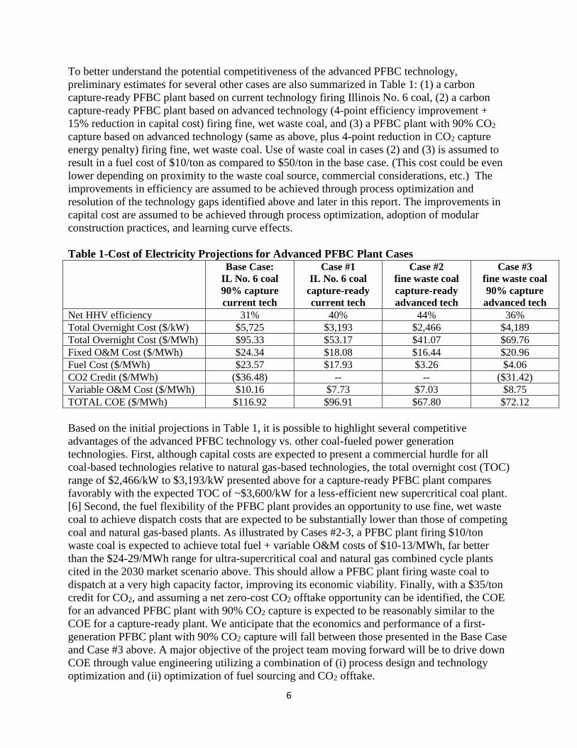
To better understand the potential competitiveness of the advanced PFBC technology,
preliminary estimates for several other cases are also summarized in Table 1: (1) a carbon
capture-ready PFBC plant based on current technology firing Illinois No. 6 coal, (2) a carbon
capture-ready PFBC plant based on advanced technology (4-point efficiency improvement +
15% reduction in capital cost) firing fine, wet waste coal, and (3) a PFBC plant with 90% CO2
capture based on advanced technology (same as above, plus 4-point reduction in CO2 capture
energy penalty) firing fine, wet waste coal. Use of waste coal in cases (2) and (3) is assumed to
result in a fuel cost of $10/ton as compared to $50/ton in the base case. (This cost could be even
lower depending on proximity to the waste coal source, commercial considerations, etc.) The
improvements in efficiency are assumed to be achieved through process optimization and
resolution of the technology gaps identified above and later in this report. The improvements in
capital cost are assumed to be achieved through process optimization, adoption of modular
construction practices, and learning curve effects.
Table 1-Cost of Electricity Projections for Advanced PFBC Plant Cases
Base Case:
IL No. 6 coal
90% capture
current tech
Case #1
IL No. 6 coal
capture-ready
current tech
Case #2
fine waste coal
capture-ready
advanced tech
Case #3
fine waste coal
90% capture
advanced tech
Net HHV efficiency 31% 40% 44% 36%
Total Overnight Cost ($/kW) $5,725 $3,193 $2,466 $4,189
Total Overnight Cost ($/MWh) $95.33 $53.17 $41.07 $69.76
Fixed O&M Cost ($/MWh) $24.34 $18.08 $16.44 $20.96
Fuel Cost ($/MWh) $23.57 $17.93 $3.26 $4.06
CO2 Credit ($/MWh) ($36.48) -- -- ($31.42)
Variable O&M Cost ($/MWh) $10.16 $7.73 $7.03 $8.75
TOTAL COE ($/MWh) $116.92 $96.91 $67.80 $72.12
Based on the initial projections in Table 1, it is possible to highlight several competitive
advantages of the advanced PFBC technology vs. other coal-fueled power generation
technologies. First, although capital costs are expected to present a commercial hurdle for all
coal-based technologies relative to natural gas-based technologies, the total overnight cost (TOC)
range of $2,466/kW to $3,193/kW presented above for a capture-ready PFBC plant compares
favorably with the expected TOC of ~$3,600/kW for a less-efficient new supercritical coal plant.
[6] Second, the fuel flexibility of the PFBC plant provides an opportunity to use fine, wet waste
coal to achieve dispatch costs that are expected to be substantially lower than those of competing
coal and natural gas-based plants. As illustrated by Cases #2-3, a PFBC plant firing $10/ton
waste coal is expected to achieve total fuel + variable O&M costs of $10-13/MWh, far better
than the $24-29/MWh range for ultra-supercritical coal and natural gas combined cycle plants
cited in the 2030 market scenario above. This should allow a PFBC plant firing waste coal to
dispatch at a very high capacity factor, improving its economic viability. Finally, with a $35/ton
credit for CO2, and assuming a net zero-cost CO2 offtake opportunity can be identified, the COE
for an advanced PFBC plant with 90% CO2 capture is expected to be reasonably similar to the
COE for a capture-ready plant. We anticipate that the economics and performance of a first-
generation PFBC plant with 90% CO2 capture will fall between those presented in the Base Case
and Case #3 above. A major objective of the project team moving forward will be to drive down
COE through value engineering utilizing a combination of (i) process design and technology
optimization and (ii) optimization of fuel sourcing and CO2 offtake.
7
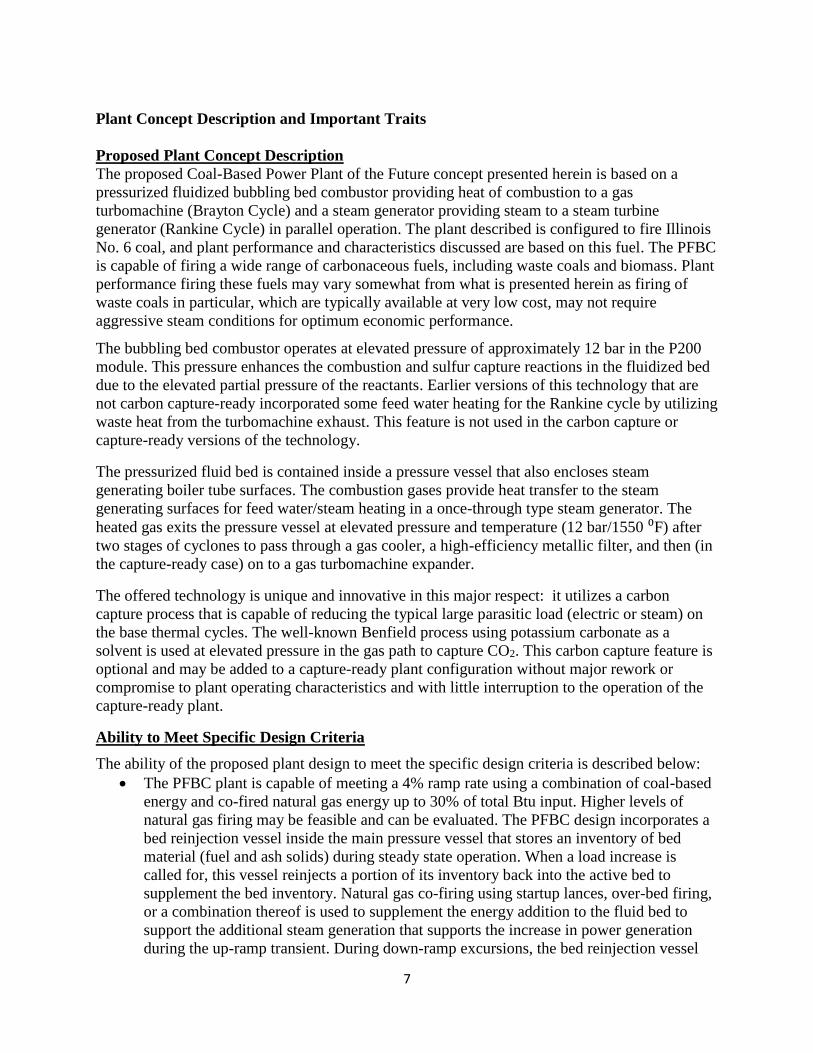
Plant Concept Description and Important Traits
Proposed Plant Concept Description
The proposed Coal-Based Power Plant of the Future concept presented herein is based on a
pressurized fluidized bubbling bed combustor providing heat of combustion to a gas
turbomachine (Brayton Cycle) and a steam generator providing steam to a steam turbine
generator (Rankine Cycle) in parallel operation. The plant described is configured to fire Illinois
No. 6 coal, and plant performance and characteristics discussed are based on this fuel. The PFBC
is capable of firing a wide range of carbonaceous fuels, including waste coals and biomass. Plant
performance firing these fuels may vary somewhat from what is presented herein as firing of
waste coals in particular, which are typically available at very low cost, may not require
aggressive steam conditions for optimum economic performance.
The bubbling bed combustor operates at elevated pressure of approximately 12 bar in the P200
module. This pressure enhances the combustion and sulfur capture reactions in the fluidized bed
due to the elevated partial pressure of the reactants. Earlier versions of this technology that are
not carbon capture-ready incorporated some feed water heating for the Rankine cycle by utilizing
waste heat from the turbomachine exhaust. This feature is not used in the carbon capture or
capture-ready versions of the technology.
The pressurized fluid bed is contained inside a pressure vessel that also encloses steam
generating boiler tube surfaces. The combustion gases provide heat transfer to the steam
generating surfaces for feed water/steam heating in a once-through type steam generator. The
heated gas exits the pressure vessel at elevated pressure and temperature (12 bar/1550 ⁰F) after
two stages of cyclones to pass through a gas cooler, a high-efficiency metallic filter, and then (in
the capture-ready case) on to a gas turbomachine expander.
The offered technology is unique and innovative in this major respect: it utilizes a carbon
capture process that is capable of reducing the typical large parasitic load (electric or steam) on
the base thermal cycles. The well-known Benfield process using potassium carbonate as a
solvent is used at elevated pressure in the gas path to capture CO2. This carbon capture feature is
optional and may be added to a capture-ready plant configuration without major rework or
compromise to plant operating characteristics and with little interruption to the operation of the
capture-ready plant.
Ability to Meet Specific Design Criteria
The ability of the proposed plant design to meet the specific design criteria is described below:
• The PFBC plant is capable of meeting a 4% ramp rate using a combination of coal-based
energy and co-fired natural gas energy up to 30% of total Btu input. Higher levels of
natural gas firing may be feasible and can be evaluated. The PFBC design incorporates a
bed reinjection vessel inside the main pressure vessel that stores an inventory of bed
material (fuel and ash solids) during steady state operation. When a load increase is
called for, this vessel reinjects a portion of its inventory back into the active bed to
supplement the bed inventory. Natural gas co-firing using startup lances, over-bed firing,
or a combination thereof is used to supplement the energy addition to the fluid bed to
support the additional steam generation that supports the increase in power generation
during the up-ramp transient. During down-ramp excursions, the bed reinjection vessel

8
can take in some of the bed inventory to assist in maintaining the heat transfer
requirements. Coal flow is reduced during a down-ramp transient. Steam bypass to the
condenser may also be used in modulating a down-ramp transient.
• The PFBC plant requires 8 hours to start up from cold conditions on coal. Startup from
warm conditions requires from 3 to 6 hours, depending on the metal and refractory
temperatures existing when a restart order is given. These start up profiles are given in
Appendix E. Startup from hot conditions (defined as bed temperature at or near 1500 ⁰F,
and main steam pipe temperature above approximately 800 ⁰F) requires less than 2 hours
on coal; this time is reduced to approximately 1 to 2 hours with natural gas co-firing. It
should be noted that very short startup times are not compatible with use of a
supercritical steam cycle with high main and reheat steam design temperatures. There are
two compelling factors that mitigate against very fast starts for this type of steam cycle:
first are the severe secondary stresses induced in heavy wall piping and valves necessary
for supercritical steam conditions. Longer warmup times are necessary to avoid
premature material failures and life-limiting changes in the pressure part materials for the
piping, valves, and high-pressure turbine components. The second limiting factor on
rapid startup times is the feed water chemistry limitation inherent in supercritical steam
cycles. After a complete shutdown, condensate and feed water chemistry typically
requires some length of time to be returned to specification levels. Assuring long material
life and preventing various kinds of corrosion mechanisms from becoming an issue
requires that water chemistry be brought to the proper levels prior to proceeding with a
full startup from cold, no-flow conditions. Resolution of this entire bundle of issues could
be viewed as a “Technology Gap” of sorts, requiring investigation to see if any realistic
remedies can be developed.
• The PFBC can turn down to the required 20% load and below by reducing the number of
modules in operation. A 20% power level can be achieved by operating one of four P200
modules at approximately 80% load or two modules at about 40% load each. Operation is
expected at full environmental compliance based on known previous operational
experience.
• The PFBC technology offered employs 90% CO2 capture, but it can also be offered as
fully CO2 capture-ready without the capture equipment installed. The addition
(construction) of the CO2 capture equipment may be performed while the plant is in
operation without interference, and the switch-over to CO2 capture, after construction is
completed, can be made by opening/closing specific valves to make the transition while
at power. This is accomplished one PFBC module at a time to minimize any impacts on
system operation.
• The proposed PFBC plant will incorporate a Zero Liquid Discharge system. The plant
design will be integrated with the fuel preparation facility to incorporate internal water
recycle and to reuse water to the maximum extent. This will minimize the capacity, and
thereby the cost, of any required ZLD system.
• Solids disposal is characterized by two major streams of solids: bed ash and cyclone and
filter ash. The ash material has mild pozzolanic properties, and it may be landfilled or
used in a beneficial way to fabricate blocks or slabs for landscaping or light-duty
architectural applications. The ash products are generally non-leachable as demonstrated
by PFBC operations in Sweden and Japan.
• Dry bottom and fly ash discharge: PFBC ash (both bed and fly) is dry. Discharge is made
through ash coolers that provide some heat recovery into the steam cycle condensate

9
stream. The cooled ash is discharged into ash silos and then off-loaded into closed ash
transport trucks for ultimate disposal or transport to a facility for use in manufacture of
saleable end products, as noted above.
• Efficiency improvement technologies applicable to the PFBC will include neural network
control features and learning models for plant controls balancing air supply against fuel
firing rate (excess air), ammonia injection for SNCR, bed performance removing sulfur,
and other opportunities to optimize overall performance.
• The limitation of air heater outlet temperatures is not applicable to PFBC technology.
• High-efficiency motors will be used for motor-driven equipment when and where
applicable. Electric generators will be specified to be constructed to state-of-the-art
efficiency standards.
• Excess air levels will be maintained at appropriate levels to optimize the operation of the
overall PFBC Brayton and Rankine cycles, and the sulfur capture chemical reactions in
the bubbling bed. A 12% excess air limit may or may not be applicable to this
technology. Further evaluation is required. The PFBC technology does not include any
component similar to a PC or CFB boiler air heater. However, attempts will be made to
minimize leakage of hot gas that could result in loss of recoverable thermal energy.
• The consideration of sliding pressure vs. partial arc admission at constant throttle
pressure will be made during Phase II.
• A self-cleaning condenser will be employed for the steam cycle. The attainment of
consistent 1.5 in Hg backpressure is achievable on an annual average basis for the
proposed site location. However, summer peak backpressures are likely to reach 2.0
inches or more. This is a consequence of the statistically highly probable occurrence of
high ambient wet bulb temperatures above 70 ⁰F. Using aggressive design parameters for
the heat sink, including a terminal temperature difference of 5 °F for the condenser, 7 or 8
⁰F for the cooling tower approach, and a 17 or 18 ⁰F range for the circulating water
system results in a condensing temperature of at least 99 or 100 ⁰F at 70 ⁰F ambient wet
bulb temperature, which corresponds to a backpressure of 2.0 in Hga. Therefore, any time
ambient wet bulb temperatures exceed 70 ⁰F, back pressure will exceed 2.0 in Hga. A
back pressure of 1.5 in Hga (in the summer above 70 °F wet bulb temperature) might be
maintained by use of a sub-dew point cooling tower technology. This is a relatively new
innovation that promises to reduce the cooling water temperature produced by an
evaporative cooling tower by adding the necessary components of the sub-dew point
system to a relatively conventional evaporative cooling tower. Although the efficacy of
the system to reduce cold water temperatures produced by an evaporative tower appears
theoretically sound, the full economics of employing this type of system remain to be
demonstrated in a commercial setting.
• The use of an add-on FGD system is not required for PFBC technology to meet the stated
sulfur removal target, as all sulfur capture is performed in the bubbling pressurized bed to
achieve the specified 97.3% sulfur capture. When CO2 capture is employed, additional
sulfur capture is required ahead of the Benfield capture process. This additional polishing
step reduces sulfur emissions to a level characterized by greater than 99.5% removal.
• Other low-cost solutions will be identified as applicable during the Phase II pre-FEED
study.
10
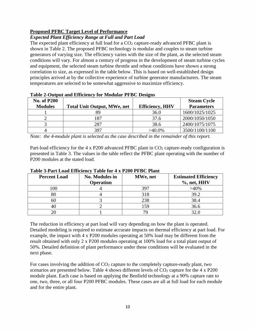
Proposed PFBC Target Level of Performance
Expected Plant Efficiency Range at Full and Part Load
The expected plant efficiency at full load for a CO2 capture-ready advanced PFBC plant is
shown in Table 2. The proposed PFBC technology is modular and couples to steam turbine
generators of varying size. The efficiency varies with the size of the plant, as the selected steam
conditions will vary. For almost a century of progress in the development of steam turbine cycles
and equipment, the selected steam turbine throttle and reheat conditions have shown a strong
correlation to size, as expressed in the table below. This is based on well-established design
principles arrived at by the collective experience of turbine generator manufacturers. The steam
temperatures are selected to be somewhat aggressive to maximize efficiency.
Table 2-Output and Efficiency for Modular PFBC Designs
No. of P200
Modules Total Unit Output, MWe, net Efficiency, HHV
Steam Cycle
Parameters
1 89 36.0 1600/1025/1025
2 187 37.6 2000/1050/1050
3 287 38.6 2400/1075/1075
4 397 >40.0% 3500/1100/1100
Note: the 4-module plant is selected as the case described in the remainder of this report.
Part-load efficiency for the 4 x P200 advanced PFBC plant in CO2 capture-ready configuration is
presented in Table 3. The values in the table reflect the PFBC plant operating with the number of
P200 modules at the stated load.
Table 3-Part Load Efficiency Table for 4 x P200 PFBC Plant
Percent Load No. Modules in
Operation
MWe, net Estimated Efficiency
%, net, HHV
100 4 397 >40%
80 4 318 39.2
60 3 238 38.4
40 2 159 36.6
20 1 79 32.0
The reduction in efficiency at part load will vary depending on how the plant is operated.
Detailed modeling is required to estimate accurate impacts on thermal efficiency at part load. For
example, the impact with 4 x P200 modules operating at 50% load may be different from the
result obtained with only 2 x P200 modules operating at 100% load for a total plant output of
50%. Detailed definition of plant performance under these conditions will be evaluated in the
next phase.
For cases involving the addition of CO2 capture to the completely capture-ready plant, two
scenarios are presented below. Table 4 shows different levels of CO2 capture for the 4 x P200
module plant. Each case is based on applying the Benfield technology at a 90% capture rate to
one, two, three, or all four P200 PFBC modules. These cases are all at full load for each module
and for the entire plant.

11
The first efficiency column (“Current State-of-the-Art”) presents estimated efficiency values for
the configuration described in the Heat/Mass Balance diagrams in Appendix F. This
configuration is based on currently available materials of construction, design experience, and
heat transfer fluid availability. The data in this column are based on the use of a new
turbomachine in lieu of the GT35P, which is not configured to be compatible with CO2 capture
as designed. In all other respects, the efficiency levels in this column reflect the use of current
technology materials and practices. The second efficiency column (“Advanced State-of-the-Art”)
is based on resolution of Technology Gap #4 identified in the section “Technology Development
Pathway Description.” The principal advance that would contribute to the higher efficiency
levels is the use of advanced steam cycle alloys allowing use of the higher steam temperatures,
including the use of double reheat. Resolving the “Other Gaps” identified in the “Technology
Development Pathway Description” may contribute additional improvements vs. the Advanced
State-of-the-Art case, but defining these would require additional effort beyond the scope of this
preliminary assessment.
Table 4-Efficiency with CO2 Capture for 4 x P200 PFBC Plant
No. of Modules
with Capture
% Capture, Total
Plant
Estimated Efficiency,
%, HHV, Current
State-of-the-Art
Estimated Efficiency,
%, HHV, Advanced
State-of-the-Art
0 0 >40 >44%
1 22.5 37.8 42
2 45.0 35.5 40
3 67.5 33.3 38
4 90.0 31 36
The impact of extraction steam from the steam turbine generator (STG) for the purpose of
regeneration of CO2 solvent is shown graphically at the 100% and 20% load points in Figure 1.
These load points are defined as 100% rated steam turbine throttle flow and 20% steam turbine
throttle flow. Linear interpolation is acceptable between the load points presented as a reasonable
first approximation for intermediate load points. The impacts shown are the delta MWe decrease
in STG output due to steam extraction for solvent regeneration. The impact is not constant in
terms of percent of MWe output across the load range because as STG power output is reduced,
steam extraction pressures after the first (control) stage will decrease. Since the solvent
regeneration process requires steam input at essentially a constant pressure and enthalpy, it is
necessary to either introduce a controlled extraction valve into the steam turbine or to shift to
progressively higher extraction points as load decreases. Taking extractions from higher stages
has a larger impact on the steam cycle; the introduction of a controlled extraction will also have
an impact and also increase capital costs and control complexity. The graph below is based on
the use of a control valve in the IP/LP crossover to maintain pressure entering the LP turbine
section.

12
Figure 1-Impact of Regeneration Steam on STG Output
Emissions Control Summary
Air emissions for the PFBC technology are dependent on the coal and/or supplementary fuels
fired. For the Illinois No. 6 coal selected for the case presented herein, targeted emissions are
presented in Table 5. For different fuels and different sites, which may have widely varying
emissions limits, additional measures may be required to meet these more stringent limits. The
control of emissions to the limits stated in the DOE solicitation is accomplished as follows.
SO2 is controlled by capture of sulfur in the pressurized bubbling bed. Limestone sorbent is
incorporated in the fuel paste feed. The calcium in the limestone reacts with the sulfur in the coal
to form calcium sulfate; the high partial pressure of oxygen in the pressurized bed assures that
the material is sulfate (fully oxidized form) instead of sulfite. To achieve 97.3 % sulfur removal,
in-bed capture is sufficient. When CO2 capture is applied to the PFBC plant or if higher levels of
sulfur capture are required, a polishing step is added to the gas path to achieve >99.5% sulfur
capture.

13
Table 5-Expected Emissions for P200 Module Firing Illinois No. 6 coal
Pollutant
DOE
Target,
lb/MWh
DOE
Target,
lb/MM Btu
PFBC, lb/MM
Btu Comments
SO2 1.00 0.117 <0.03 Based on 97.3% capture
in-bed, with added
polishing step (required by
Benfield process)
NOx 0.70 0.082 0.05 Catalyst not required
PM (filterable) 0.09 0.0105 0.001 with metal
filter (per Mott
Inc. quote 2015)
Based on metallic filter
Hg 3 X 10⁻⁶ 0.35 X 10⁻⁶ <0.35 X 10⁻⁶ Activated carbon bed in
gas path.
HCl 0.010 0.0012 <0.0012 Cl capture of 99.5% is
required based on the high
Ill. 6 Cl content.
The bed functions at a constant 1550 ⁰F temperature, a temperature at which the NOx forming
reactions are very slow (kinetically) and do not lead to any meaningful thermal NOx production.
NOx that is formed is largely a product of fuel-bound nitrogen, as thermal NOx creation is
minimized. The use of selective non-catalytic reduction (SNCR) reduces any NOx to very low
levels (< 0.05 lb/MM Btu).
In this version of the PFBC technology, a metallic filter is used to capture particulate matter
(PM). The gas path leaving the PFBC vessel first encounters two stages of cyclones, which
remove approximately 98% of the PM. The metallic filter removes over 99.5% of the remaining
PM, resulting in very low PM emissions. This also enables the gas to be reacted with CO2
capture solvent and to be expanded in conventional gas expanders. The use of special expander
materials and airfoil profiles is not required.
The fate of Hg and Cl requires detailed evaluation in Phase II. However, at this time, the
following rationale is offered in support of our belief that these elements will be controlled to
within regulatory limits. A significant portion of the Hg and Cl will be reacted to form a solid
compound and will be captured by the two stages of cyclones inside the PFBC vessel and the
metal gas filter (external to the vessel) operating at 99.5% plus efficiency. That leaves Hg and Cl
in the vapor phase. The gas will pass in succession through the following:
1. A sulfur polishing stage using an alkaline sorbent such as sodium hydroxide
2. A deep bed of activated carbon for capture of elemental Hg
3. The UOP Benfield potassium carbonate CO2 capture scrubber.
It is believed that the two stages of scrubbing and the activated carbon bed, in series, will capture
a very high percentage of the Hg and Cl that remained in the gas after the cyclone/filter stages.
The Hg concentration in the flue gas after the carbon bed is estimated at <0.001 ppb by volume.
The HCl concentration in the flue gas after the sodium hydroxide SO2 scrubber and UOP

14
Benfield process is estimated to be in a range representing 99.5%+ removal, or <0.0012 lb/MM
Btu. For both Hg and HCl, therefore, it is expected that emissions will be below the DOE
specified values of 3 X 10⁻⁶ lb/MWh and 0.010 lb/MWh, respectively.
CO2 Control Strategy
The CO2 capture strategy employed for the proposed advanced PFBC plant is to couple the
Benfield process with the P200 gas path to capture CO2 at elevated pressure and reduced
temperature. Regenerative reheating of the gas is utilized to recover most of the thermal energy
in the gas to maximize energy recovery and improve thermal efficiency. The CO2 capture is
applied in a modular manner, so that the quantity of CO2 captured may be tailored to the needs of
each specific project. Performance is presented herein for a 90% capture case.
Brief Description of the Proposed System
Size of the Commercial Offering
The base case advanced PFBC plant proposed herein includes 4 x P200 modules with a net
output of 302 MWe with 90% CO2 capture (or 397 MWe net in the carbon capture-ready
configuration). However, the size of the commercial PFBC power plant can vary as explained
above under Proposed PFBC Target Level of Performance. Table 2 shows performance for four
different size plants (in the CO2 capture-ready configuration) using different numbers of P200
modules. (Total unit output does not increase linearly in proportion to the number of modules as
the efficiency of the steam cycle increases as the unit size is increased. More aggressive steam
throttle pressures and temperatures are selected as unit size increases to take advantage of
different steam cycle parameters.)
Advanced Technology Aspects
Advanced technology aspects of the proposed PFBC plant include the incorporation of the
Benfield process at elevated pressure and reduced temperature to capture CO2 from the
combustion product gases. The PFBC plant with multiple P200 modules is coupled to a
commercial state-of-the-art supercritical steam cycle to maximize thermal efficiency. Prior P200
applications have utilized sub-critical steam cycles. The control system for the entire plant will
employ state-of-the-art system architecture and components to maximize performance and
minimize emissions. A cut-away illustration of the P200 PFBC vessel is shown in Figure 2
below.

15
Figure 2-Cut-away view of P200 PFBC Pressure Vessel
List of Components not Commercially Available
The components comprising the PFBC power plant are presented in the section entitled
Technology OEMs. The only component that is not currently commercially available is the gas
turbomachine that replaces the GT35P gas turbine. Baker Hughes General Electric has provided
a letter of cooperation (see Appendix G) for design and delivery of a replacement turbomachine
tailored to the requirements of the P200 PFBC with CO2 capture. Other qualified vendors may
also offer solutions but have not offered a commitment letter as of the time of this submittal.
Block Diagram of Integrated System
The system is presented in a series of three block diagrams. A block diagram of the gas path for
the integrated Base Case PFBC system (in CO2 capture-ready configuration) is presented in
Figure 3. The system with CO2 capture installed is shown in Figure 4. Figure 5 presents the
steam cycle as it relates to the PFBC vessel and gas turbomachines. Heat and mass balance
diagrams for the 4 x P200 plant with capture and in a capture-ready configuration are presented
in Appendix F. In addition, the heat and mass balance diagrams are given for part-load cases for
the capture-ready plant and for PFBC plants of different sizes (1 x P200, 2 x P200, and 3 x P200
- all capture ready).

16
Figure 3-PFBC without CO2 Capture (Capture-Ready Configuration)
Figure 4-PFBC with CO2 Capture

17
Figure 5-Steam Cycle Block Diagram Related to PFBC (simplified)
The original gas turbomachine used in early P200 configurations without carbon capture is the
ABB GT35P shown in Figure 6. This machine is employed in plants still in operation located in
Cottbus, Germany, and Stockholm, Sweden.
Figure 6-Elevation View of GT35P Gas Turbine
The new PFBC configuration described herein requires a new machine for two reasons: first, the
GT35P is no longer in production and restoring production would require a major commercial
investment. Second, the addition of CO2 capture requires that certain modifications be made to

18
the machine, extensive enough that a new design is most likely a preferred option. The new
machine required is presented in Figure 7 below.
Figure 7-Schematic Diagram of New Turbomachine for P200 Module (one required per
module)
Description of Each Process Block
A brief description of each block incorporated in the block diagrams follows:
• Coal Preparation and Feeding
− The coal preparation and feeding systems used by the reference plant configured for
firing Illinois No. 6 coal consist of conventional coal receiving and unloading
equipment, also incorporating a stacker-reclaimer and primary coal crushing
equipment. The crushed, reclaimed coal is sent to fuel preparation for milling to final
size and mixing with ground limestone to form a pumpable paste with nominal 26%
moisture by weight.
• PFBC
− The PFBC pressure vessel contains a complete fluidized bed boiler and gas path
components inside a large pressure vessel. There are several ancillary components as
well, related to startup, shutdown, and accommodation of transient operation. The
principal parts of the boiler are the fluidized bed furnace and the various heat transfer
tube bundles for economizer, boiler, superheat, and reheat. The gas path includes a
down-comer to convey the compressed air to the bottom of the fluidized bed, and gas
piping to and through the cyclones and then to the PFBC gas exit. Also incorporated
into the PFBC vessel are the hot gas cyclones (two stages) that separate 98% plus of
the particulate matter from the hot flue gas exiting the PFBC vessel. The hot gas
leaves the PFBC vessel and passes to the gas cooler.
− The gas cooler is a shell and tube type heat exchanger (gas on the shell side)
providing supplementary superheating and reheating for the steam cycle.
− The gas expander is a part of the special turbomachine presented in Figure 7 above.
This expander operates at a relatively low temperature of 790 ⁰F for the capture-ready

19
case and can therefore utilize inexpensive materials and uncooled design more typical
of steam turbine design parameters than of gas turbine design parameters. The
expander design quoted by Dresser Rand for a recent PFBC study was in fact
prepared by their steam turbine production unit and not their gas expander production
unit.
− The exhaust gas from the expander in this design configuration is sent directly to the
plant stack for exhaust to the atmosphere. The gas temperature is approximately 270
⁰F at this point in the gas path for the capture-ready case, an appropriate temperature
for discharge. The discharge temperature for 90% capture case is approximately 200
°F.
− The air compressor is comprised of two types of units. The low-pressure compressor
is a multi-stage centrifugal design, while the high-pressure unit is an axial flow design
with variable inlet guide vanes. A shell and tube intercooler is used between the
compressors to reduce the air temperature and thereby reduce compressor power
consumption.
− Particulate removal is performed in a metal multi-element filter contained in a
pressure vessel rated for the hot gas design conditions (downstream of the gas cooler,
pressure is ~12 bar, temperature is ~800 ⁰F). The filter is backpulsed to clean the
filter elements, one at a time, while on line. The PM blown from the filter is sent to
join the cyclone ash (fly ash) in its respective handling system.
− The heat transfer loop (in the CO2 capture-equipped case) is comprised of two shell
and tube heat exchangers coupled by a circulating loop of Dowtherm A that
regeneratively cools and then reheats the gas (shell sides of the heat exchangers).
− The UOP Benfield Process (in the CO2 capture-equipped case) is comprised of a
sulfur scrubbing subsystem followed by the potassium carbonate scrubber and
regenerator, and related miscellaneous components. The Benfield process removes a
nominal 90% of the CO2 from the pressurized, cooled gas. The reheated gas (from
one of the pair of heat exchangers noted above) passes to the gas expander for power
generation.
Use of Other Fuels in Conjunction with Coal
The proposed PFBC plant is capable of firing other solid fuel in addition to bituminous coal. The
Process Test facility in Finnspong, Sweden, has fired the following solid materials as part of a
validation program. Polish Coal (fired at Vartan, Sweden)
• Spanish Lignite fired at Escatron, Spain (high moisture, high ash, high sulfur)
• Brown Coal fired at Cottbus, Germany (typical brown coal)
• Petroleum Coke
• Anthracite
• Olive Pips
• Palm Nut Shells
• Wood chips
• Oil Shale
• Sewage Sludge
Additional solid fuels, including wet, fine waste coal from CONSOL’s mining operations in
Northern Appalachia, were fired at the PFBC-EET/CONSOL test facility in South Park, PA.

20
The selection of paste feed vs. dry feed is made based on the moisture content of the fuel plus
other characteristics. For this proposed application, a paste feed has been selected to allow for
the potential to incorporate wet, fine waste coal as a low-cost fuel feedstock.
Description of Integrated Energy Storage
The PFBC technology incorporates energy storage in the form of a bed reinjection vessel that
stores a portion of the fluid bed material during normal operation. The bed material provides a
buffering effect for load changes - it ingests bed material during a load reduction and reinjects
the material into the bed during a load increase. This enables the integrated fluid bed/boiler
combination to respond rapidly to load transients in both directions. Although the energy storage
is small in relation to the output of the plant, it provides the “bridge” between instant output and
long-term energy storage in the fuel. Should all of the bed material be held in the reinjection
vessels, there would be about 84 MMBtu of energy stored per P200, as stated, a small amount.
Power System Working Fluid and Process Conditions
The power system working fluids are air/gas (combustion products) and steam/feed water. The
system operates by utilizing a Brayton cycle and a Rankine cycle in parallel. Although this
involves use of a gas turbomachine and a steam turbine, the cycles are not integrated in a cascade
as in a typical gas turbine combined cycle. The traditional combined cycle coupling is not
advantageous for the PFBC configuration with CO2 capture wherein the cycles operate in
parallel but are not coupled. The use of the Brayton cycle integrated with the rest of the PFBC
plant provides the pressurized gas conditions that make the Benfield process advantageous for
CO2 capture. Refer to the block diagrams above and the heat/mass balances in Appendix E for
more information on process conditions.
Features that Minimize Water Consumption
The task of minimizing water consumption is influenced by the site selection and the fuel that is
to be fired in the PFBC. The largest consumer of water in a thermal power plant is typically the
evaporative cooling tower, where this is employed as a heat sink. Another significant user of
water is steam cycle makeup for a typical Rankine cycle. Also of interest is makeup water for an
evaporative cooler for the inlet of a gas turbomachine, as employed in this PFBC technology
application. Finally, a significant amount of water can be required for fuel preparation where
paste feed (as opposed to dry feed) is used for the PFBC.
The overall concept to be employed in the PFBC plant design is to recycle water internally
within the facility and minimize the need for makeup water. Starting with the evaporative
cooling tower, the use of higher cycles of concentration (up to 5 or 6) will minimize the quantity
of blowdown and makeup required.
The use of paste feed for an application involving utilization of pond fines and/or tailings can be
configured to recycle the water from the fines in the fuel preparation plant. The fuel preparation
process can, therefore, minimize the need for makeup water.
Steam cycle makeup water use can be minimized by limiting blowdown from the steam cycle by
using a condensate polisher and using steam cycle blowdown for other purposes, such as
diversion to the cooling tower as makeup to that system.

21
The use of evaporative cooling for the gas turbomachine would be utilized during periods of high
ambient temperature to maintain the mass flow of air to the PFBC, and thereby maintain total
power output. Water quality for this purpose must be maintained at relatively high levels to avoid
fouling the compressor with mineral deposits.
Considering the factors described above, an integrated water usage and recycling plan will be
accomplished for the proposed plant when definitive site and makeup water characteristics are
properly defined.
Techniques to Reduce Design, Construction, and Commissioning Schedules
Modularization
Reductions of cost and schedule parameters for the PFBC technology include the inherent
modular nature of significant portions of the design. The most significant feature of the PFBC
design is the P200 module. This module is used in multiples to achieve larger unit sizes. Each
module is identical and based on a single set of drawings, specifications, etc. In constructing a
multi-module plant, reduction of costs is achieved by quantity discounts and reliance on a
learning curve effect. Sequencing and scheduling of work crews will take advantage of the
learning curve to reduce costs and schedule time for complete build-out of the plant.
Within any individual PFBC vessel, components will be shop-fabricated to the maximum extent
and shipped to the job site ready to be installed. This includes heat transfer surfaces, piping and
valves, etc. The PFBC vessel will be field-erected in most cases; this work will be scheduled
when access is not required for installation of internal components. For sites that are accessible
by water (coastal or river), it is possible to completely construct the PFBC vessel and most of its
internals and ship this to the site by barge.
A significant portion of the PFBC plant is scalable rather than modular. This includes the steam
turbine building and components within it, the fuel preparation facility (located nearby), the
water treating building and equipment, and typical ancillary facilities such as a site warehouse,
administration building, etc. However, all these items may utilize modular fabrication and
assembly techniques to reduce cost and speed up installation time. The construction site will be
organized and optimized to accept deliveries to a staging or laydown area, then a pre-assembly
area, and then allow for installation or erection with minimal handling and lifting.
Advanced Process Engineering
The PFBC plant described herein utilizes advanced process engineering in the coupling of the
PFBC gas path to the Benfield cycle. The Benfield process operates efficiently and at moderate
cost at elevated pressure (12 bar) and reduced temperature (300 ⁰F). These gas conditions are
achieved by cooling the gas in a shell and tube heat exchanger, passing it through the Benfield
process vessels, and then regeneratively reheating the gas in a second shell and tube heat
exchanger. A high temperature fluid such as DowTherm A circulates between the two heat
exchangers to accomplish the required heat transfer. This fluid is commonly used in concentrated
solar thermal applications to generate steam for a Rankine cycle.

22
Technology Development Pathway Description
Current State-of-the-art with Shortcomings, Limitations and Challenges
The current focus for developing new coal-fired power plants with CO2 capture seems to indicate
that either a supercritical PC unit with an amine-based solvent for CO2 capture or an IGCC with
a physical solvent (such as Selexol) are considered state-of-the-art technology. The shortcomings
of these technologies include a relatively large energy penalty, especially for the supercritical PC
plant, high capital cost, especially for the IGCC plant, and high variable operating and
maintenance costs that impede the ability of the plant to economically dispatch. These
technologies also have limited operating and fuel flexibility, further challenging their ability to
operate economically, and are not particularly well-suited for small-scale, modular construction.
PFBC Overcomes the Shortcomings, Limitations and Challenges
As has been discussed, the PFBC technology meets most of the requirements in the Performance
Work Statement and has proposed means for filling any gaps. Among others, it has high plant
efficiency (>40% HHV in capture-ready configuration), is modularized, has near-zero emissions,
and is capable of achieving high ramp rates.
Already in its current state, the PFBC technology offers a pathway to efficient, low-emission,
modular, cost-competitive coal combustion technology with post-combustion CO2 capture for
small-to-medium size power plants. Some of the specific features are:
• Excellent fuel flexibility (handles low Btu fuels, wet fuels, and fines efficiently)
• Typical combustion efficiencies close to 100%
• High plant efficiency and high carbon burnout (low CO and loss on ignition)
• Compact boiler design to significantly lower the required quantity of expensive materials
• Useful ash products
• Low water consumption
• Readiness for CO2 capture
• Low emission levels without use of catalyst or polishing stages. (However, the Benfield
process, when added, will in most cases require additional SO2 removal to meet process
requirements).
Pending availability, carbon-neutral biomass fuel can be mixed in with the coal. PFBCs have
combusted up to a 40% biofuel/coal mix, meaning that they can achieve near-zero carbon
emissions while capturing less than 90% of the emissions from the combined biofuel/coal blend.
Such a fueling strategy can help to improve the capital cost, operating cost, and emissions
performance of the plant relative to competing technologies.
Ash from a PFBC boiler contains virtually no free lime and no sulfites or sulfides, making it easy
and safe to handle. The ash is self-binding with water without any additives. If water is added the
ash will harden like concrete. The hardened ash product is water resistant and has a very low
permeability, making it suitable for synthetic gravel, landfill preparation, building material, and
aggregate for manufacture of concrete. This is a major benefit attributable to PFBC operations
with coal as it creates the potential to generate revenue from byproducts and/or to minimize
disposal costs.

23
The PFBC boiler is provided with an insulated bed reinjection vessel storing hot bed material for
fast load changes by controlling the bed mass level to benefit the load-following resources. The
need for dispatchable generation, critical ancillary services, and grid reliability in the future all
point to opportunity for advanced coal-fired power generating plants such as the advanced multi-
module PFBC plant. This type of plant is capable of achieving high efficiencies, operating
flexibly and reliably, minimizing capital cost requirements, taking advantage of low-cost fuel
sources, achieving very low emission rates, and complying with potential future restrictions on
carbon dioxide emissions.
One of the challenges we have is to design an efficient PFBC gas/ boiler steam cycle combined
with a CO2 capture process. A major disadvantage with atmospheric boilers and CO2 capture
processes is the volume of exhaust gasses that needs to be handled. In post-combustion capture
configurations, amines have been the solvent of choice for CO2 removal because of their fast
reaction rates and high capacity for absorbing CO2. The drawback for MEA and other amines is
their high heat of absorption and tendency towards thermal and oxidative degradation and
corrosive action. The post-combustion Benfield potassium carbonate CO2 capture system,
utilized by the PFBC, uses potassium carbonate as a solvent with the benefit of low heat of
absorption with lower energy penalties, low solvent cost, no degradation, and low corrosion. A
potential disadvantage with potassium carbonate is the slower reaction rate with CO2 requiring a
larger surface for the absorber. This is mitigated in the PFBC by the elevated pressure, which
increases the partial pressure of all reactants. Compared to atmospheric processes, the combined
pressurized PFBC/Benfield process results in a net size advantage.
The complete system includes a metallic filter ahead of the Benfield process to protect the
process, along with the gas expander. The metallic filter also enables the P200-based plant to
meet stringent air emissions limitations for PM.
Technical Risks/Issues and Assessed Technology Gaps and R&D Needed for
Commercialization
This section describes the technology gaps identified as needing resolution to support successful
further development of the PFBC combustion technology. The commercial P200 module has a
demonstrated record of application in Europe, Japan, and the US over the last three decades.
However, the future viability of this technology relies on resolution of several “technology gaps”
in order to continue to be technically and commercially relevant. These gaps and proposed
solutions are discussed herein.
Gap 1 - Turbomachine
The first and most important gap lies in the fact that the previously applied gas turbomachine, the
ABB GT35P, is no longer available as a commercial production item. It is also the case that even
if it were to be made available now, this machine is not well suited for adaption into the P200 gas
path with CO2 capture using the UOP Benfield process.
Recent studies dating back to 2015 and earlier have focused on design and development of a new
turbomachine that could operate in the P200 gas path and perform the necessary functions. Based
on design studies performed for DOE in the early 2000s, a relationship was developed with
Dresser Rand to design and manufacture a new turbomachine to meet PFBC requirements. At
this time, the commercial landscape has changed, and it must be recognized that the intellectual

24
property rights to the GT35P machine reside with Siemens. However, Dresser Rand is now also
under the Siemens corporate umbrella. While Dresser Rand has expressed interest in designing a
new machine to supplant the GT35P, to date, discussions with Dresser Rand are in an
exploratory stage. The CONSOL team reached out to General Electric, specifically Baker
Hughes GE, which handles the types of components required to build a replacement to the
GT35P that is compatible with integration with the UOP Benfield process. As a result, Baker
Hughes GE has provided an expression of interest and a letter of support (Appendix G).
The new machine will be comprised of low-pressure and high-pressure compressors, a hot gas
expander, a motor-generator, and necessary gearboxes, couplings, and variable speed drive
components. This machine must be able to operate with CO2 capture turned on or off, as gas
flow rates and temperatures at the expander inlet will vary significantly between the two
conditions.
The gas expander and motor generator operate at a fixed speed, with the expander running at
higher rotational speed than the motor generator (which runs at synchronous speed of 3,600 rpm).
The gas expander will likely operate at a higher speed to obtain better efficiency (rotational
speed is correlated with flow capacity, which in turn is related to machine diameter). For the size
of this application, an expander speed of 4,500 to 6,000 rpm is expected.
The compressor train (low and high pressure units) is likely to operate at the same speed as the
motor generator at full load. However, at reduced loads and during startup and ramp-up, the
compressor speed is reduced to ensure stable operation. Dynamic compression machines (axial
flow and centrifugal flow) do not turn down (provide reduced flow rates) very well, and other
solutions such as bleeds and blow-offs are required to manage the machine. The provision of a
variable speed device resolves this problem and allows stable operation at the best efficiency at
part load.
The definitive resolution for this technology gap is for Baker Hughes GE and/or Dresser Rand to
design a new machine to meet the specifications of PFBC-EET and Worley Group Inc. A
conceptual sketch of this machine was presented in Figure 7.
Gap 2 Integration of UOP Benfield Process
This gap involves the incorporation of the UOP Benfield process into the gas path while
preserving the air compression capability of the compressor train and the expansion capability of
the hot gas expander as an integrated machine throughout the load range and for startup,
shutdown, and trips. The incorporation of the UOP Benfield process requires that sulfur
compounds be removed to a very low level, estimated to be in the very low ppm or even down to
the ppb range (as measured by volume or mole fraction). This is accomplished by introducing an
alkaline (sodium hydroxide) scrubber, operating at the prevailing gas pressure and temperature,
to remove the sulfur. As an adjunct to this process, a deep bed of activated carbon is introduced
after the sulfur scrubber to remove mercury in the gas path in vapor form. Compounds of
mercury that are in solid form are removed upstream of the sulfur scrubber in a highly-effective
metallic element gas filter.
The integration of the UOP Benfield process with the P200 PFBC therefore requires the
following steps, in sequence:

25
• Cooling of the hot particulate-laden gas exiting the PFBC from 1550 °F to ~800 °F. This
is achieved by means of a gas cooler that performs superheat and reheat duty for the
steam cycle as an adjunct to the thermal duty performed inside the PFBC vessel in the
PFBC boiler.
• Filtration of the gas at ~800 °F to remove remaining particulate matter at a 99% plus
effectiveness. This is achieved by the hot gas filter. (Quote received from Mott during the
last round of PFBC plant studies, circa 2015).
• Further cooling of the gas to ~250 °F in a regenerative gas cooler/reheat loop utilizing
shell and tube heat exchangers and a thermal heat transfer fluid as used in solar thermal
technology applications.
• Induction of the gas into the alkaline scrubber for SO2 removal.
• Passage of the gas through the activated carbon filter for removal of mercury.
• Induction of the gas into the UOP Benfield process for CO2 capture.
• Reheat of the gas using the second heat exchanger (part of a pair that performs the
regenerative cooling and reheating) back up to ~700 °F.
• Expansion of the gas from ~12 bar to 1 bar, producing shaft power for the turbomachine
described above.
• Exhaust of the gas to the plant stack.
The definitive resolution of this gap is the detailed design of the entire gas path, including the
turbomachine, SO2 and UOP Benfield scrubbers, etc. This is not a technology gap, per se, but a
design gap.
Gap 3 Redesign of the P200 Boiler for Supercritical Steam Conditions
This gap is resolved by detailed design of the boiler steam coil surfaces inside the PFBC vessel
for supercritical steam conditions. This will likely require replacing a considerable amount of
tube surface now made of T22 material with heavier wall tube made of T91 material (to handle
the increased pressure and temperature). This involves all the tube surface, since even the
economizer surface and primary superheat surface will have to deal with significantly increased
pressure, and the finishing superheat surface and reheater surface will have to deal with the
higher temperatures selected for the supercritical case. This gap will be resolved by detailed
design and specification of alternate, commercially-available materials relative to what is in the
existing P200 boiler design.
Gap 4 Design of the PFBC Boiler for Advanced Steam Conditions
This gap has much in common with advanced pulverized coal (PC) steam plant technology gaps
in terms of steam cycle pressures and temperatures. In this regard, advances can be viewed as a
continuous process, particularly with respect to temperature. Designing for higher steam cycle
pressure (up to 5000 psi or higher) is accomplished by increasing tube wall thickness and piping
thickness. However, higher temperatures, particularly above ~1100 °F, require careful
consideration of life cycle/duty cycle issues, ASME Code acceptance, economic justifiability,
and other potential factors.
This gap is likely to be resolved in an incremental fashion in a series of small steps. As improved
high-temperature alloys become available as commercial products, they are likely to be
introduced into the design/fabrication chain slowly over time. Issues related to weldability, the

26
need for post-weld heat treatment and welder qualification, non-destructive examination
techniques and acceptability thresholds for indications will take time to resolve to the satisfaction
of the applicable codes (ASME Section 1, ASNI B31.1, etc.) and insurance and finance
underwriters.
Other Gaps
A few relatively minor gaps can be identified as having potential for performance improvement,
if resolved. These include the following:
• Use of higher-temperature heat transfer fluids for the regenerative cooling/reheat loops.
Resolution of this gap by use of higher-temperature fluids (such as molten salts as used in
certain solar thermal applications) could increase cycle efficiency (for the gas path).
Cycle studies must be performed first in order to quantify the performance benefits that
might be expected to accrue from the higher gas temperatures used in the gas path prior
to induction to the gas expander.
• Use of a gas-to-gas regenerative heat exchanger in lieu of the shell-and-tube heat
exchangers combined with the thermal heat transfer fluid. This development path is likely
to be a difficult one, if history is any guide. The development of high-temperature gas-to-
gas heat exchangers has been challenging in the past, and some of the units in question
operated at lower temperatures relative to the PFBC cycle and were smaller in size
(volumetric gas flow). Nonetheless, if a breakthrough were to be achieved in this area, it
would be useful to incorporate into the PFBC gas path for the carbon capture design case.
Summary
The principal technology gap requiring resolution for PFBC technology to advance, with or
without CO2 capture, is the provision of a replacement machine for the GT35P. There is every
expectation that this can be accomplished with the participation of a large, technically qualified
organization such as Baker Hughes General Electric. The other gaps can also be resolved with
time and technical effort. We believe that the PFBC technology is capable of deployment in the
early 2020s to meet the DOE Coal FIRST time frame, and that overcoming the principal
technology gaps will not require pilot testing of any components. These are design and
optimization activities accomplished by modeling techniques readily available to the project
team or through the cooperation of the OEMs.

27
Technology Original Equipment Manufacturers (OEM)
The equipment required to construct a 300 MWe net advanced PFBC power plant with 90% CO2
capture is described in this section. The equipment is categorized into major divisions based on
association with the functional characteristics of each system and its components. Where non-
standard equipment is required, Worley Group Inc. has had discussions with leading suppliers of
this equipment and has received assurances of cooperation in a detailed design phase. Letters
from PFBC-EET and GE are included in Appendix G.
P200 PFBC Vessel and Internals (Commercial Equipment)
The AE firm, Worley Group Inc., has worked with PFBC-EET (license holder of the PFBC
technology) and Nooter Ericson in previous design studies of multi-module P200 power plants.
A detailed preliminary design and cost estimate were prepared, but the project did not proceed to
construction. A second example is a repowering of two out of three PC steam electric power
plants in Moundsville, WV, for using two blocks of three P200 PFBC modules. This project did
not proceed to construction. The P200 equipment division includes the equipment physically
located inside the PFBC pressure vessel, all of which is commercially available. This vessel and
its internal components will be supplied and assembled at the site by Nooter Ericson. This
includes: the PFBC pressure vessel, PFBC boiler system, cyclones, bed reinjection system, bed
preheating system, ammonia injection system, PFBC fuel, sorbent, and ash systems. The scope
of these systems includes components that are largely internal with some items external to the
PFBC vessel. The systems interface with the external fuel and sorbent receiving, storage,
handling, and preparation system; and the bed ash and cyclone ash removal, depressurization,
cooling, and storage systems. All components internal to the PFBC vessel are supplied by Nooter
Ericson; external components are supplied by PFBC-EET and by balance of plant suppliers.
Fuel and Sorbent Receiving, Handling, Storage, and Preparation System (Commercial
Equipment)
The AE firm, Worley Group Inc, has worked with Farnham & Pfile on previous design studies of
multi-module P200 PFBC power plants. The subject equipment division receives fuel from
outside sources and prepares the fuel for injection in paste form into the PFBC boiler bed.
Sorbent (limestone for this application) is also received, prepared, and mixed with the fuel paste
prior to injection into the PFBC boiler fluidized bed. Individual components comprising this
system, all of which are commercially available from a number of suppliers, are:
Dry Fuel Receiving, Handling, and Sizing Subsystem - bottom dump hopper and pan feeder,
conveyors, breaker/crusher for rough coal sizing to 2” x 0.
Fuel Storage and Reclaim - reclaim conveyors, scales, sampling system, mobile yard equipment
Sorbent Receiving, Handling, and Sizing Subsystem - receiving hopper, conveyors, covered
storage/reclaim dome, stacker, tram, rake, rod mills, pneumatic conveying system, sampling
system
Fuel/Sorbent Preparation and Forwarding - sliding frames, weigh feeders, bins and rotary
feeders, transfer conveyors, paste mixer sumps and agitators, prepared fuel sumps and agitators,
prepared fuel transfer pumps
Paste Fuel Feed System - buffer silos with mixers, paste feed pumps (Putzmeister type pumps,
commercially available)

28
Ash Handling Systems (Commercial Equipment)
The ash handling system components, which are commercially available from a number of
suppliers, include recovery of bed ash from the bottom of the PFBC boiler, as well as cyclone
ash recovery from the cyclone down-legs. Both types of ash pass through tubular ash coolers that
provide some heat recovery to the condensate system. The fine PM recovered from the hot gas
metallic filter will contain a very limited amount of usable thermal energy (due to the limited
quantity). This material is mixed with the cyclone ash prior to storage in the fly ash silo, from
which it is loaded onto trucks for disposal or alternative beneficial use.
Gas Turbomachine (Equipment requiring R & D)
The gas turbomachine will be a new design, tailored and optimized to the requirements of the
PFBC cycle with CO2 capture. The AE firm, Worley Group Inc., has worked extensively in the
past with Dresser Rand (now part of Siemens) and General Electric in numerous previous gas
turbine and steam turbine power plant designs. These efforts are documented in several DOE-
sponsored reports, prepared under DOE AM26-99FT 40465. The reports are titled “Land Based
PFBC Power Plants” and “Barge Mounted PFBC Power Plants,” both circa year 2000 to 2002.
The gas turbomachine is a custom-designed machine that provides compressed air to the PFBC
boiler, and expands the hot gases after they have been filtered and the CO2 has been absorbed.
The turbomachine function is very different from the way a typical gas turbine would operate.
The turbomachine components, arranged on a common shaft, are as follows:
• Compressor (low pressure, high pressure), expander, speed reducing gearbox, electric
motor/generator, intercooler (non-rotating component, off-skid)
The OEM supplier for the turbomachine has not been determined at this early stage. It will likely
be any of the major suppliers of such equipment such as General Electric, Dresser Rand, MAN
Turbo, or possibly others. Baker Hughes General Electric has responded to an inquiry for Worley
Group that included a “mini-spec” and data sheet with a statement that they have the capability
and interest to support the project needs in a detailed design with a view to manufacture the
required equipment. This letter is presented in Appendix G.
Hot Gas Filter and Regenerative Cooling and Reheating (Commercial Equipment)
The AE firm, Worley Group, Inc., has worked with Mott and Pall, suppliers of hot gas filters (at
elevated pressure), and with Nooter, who will supply the heat transfer equipment. Worley Group,
Inc., has worked with high temperature thermal heat transfer fluids in numerous studies for EPRI
for solar thermal augmentation projects for existing coal and oil-fired steam electric power plants.
Examples of detailed design studies include solar thermal augmentation at steam electric power
stations for Hawaiian Electric, (Kahe Power Plant, Units 5 and 6, oil-fired steam electric
stations); Carolina Power and Light (Mayo Station, coal-fired station); and Tri-State
Transmission and Generation Association, Inc. (Escalante Generating Station, coal-fired station).
The hot gas filter and regenerative heating/cooling equipment are commercial equipment.
However, it would be desirable to seek and utilize advanced materials in the equipment
comprising this subsystem to improve thermal performance of the overall PFBC power plant.
This system conditions the hot gas exiting the PFBC vessel on the way to the UOP CO2 capture
system and the gas expander (part of the turbomachine mentioned above.) The AE firm, Worley
group, Inc., has worked with Nooter and UOP on previous design studies involving the PFBC
technology, and on CO2 capture utilizing the Benfield process.

29
Hot Gas Cooler
The hot gas cooler reduces the PFBC gas exit temperature from 1525 ⁰F to approximately 800 ⁰F.
The gas passes through the hot gas filter for PM removal. The gas cooler recovers the gas
thermal energy by providing superheat and reheat for portions of the steam cycle.
Hot Gas Filter
The hot gas filter removes remaining particulate matter (PM) from the hot gas exiting the PFBC
boiler. This filter is comprised of a group of metallic mesh filter elements arranged in a pressure
vessel. The filter operates at a gas temperature of 800 ⁰F and thus can use conventional low-alloy
steel materials. The filter is equipped with a back-pulse cleaning system to remove filter cake
and discharge it to the ash handling system. Suppliers of this equipment can include Mott
Corporation and Pall Corporation.
After the hot gas filter, the gas path can take one of two configurations, as follows: For a CO2
capture-ready PFBC module, the 800 ⁰F gas is routed directly to the turbomachine expander for
expansion and energy recovery. The gas bypasses the regenerative cooling and reheating heat
exchangers, sulfur polishing and CO2 capture stages described below for the case equipped with
CO2 capture. The gas exit temperature from the expander is about 270 ⁰F in the CO2 capture-
ready configuration, and the gas is routed directly to the stack with no other processing or
interactions.
Regenerative Gas Cooler
For a PFBC module equipped with CO2 capture, the gas is routed to the Regenerative Gas
Cooler and to a sulfur polishing step before being sent to the Benfield CO2 Scrubber System. The
Regenerative Gas Cooler is a shell and tube heat exchanger, which cools the gas further to ~320
⁰F prior to entering the sulfur polishing step. The sulfur polishing is required prior to induction
of the gas into the UOP CO2 scrubber. This is accomplished by a wet scrubber stage utilizing a
regenerable solvent. Parasitic loads (electric and steam) are expected to be modest since most of
the sulfur is captured in the PFBC bed. This will minimize the need for steam to regenerate the
solvent. The regenerative gas cooler transfers heat to a circulating loop of high temperature
thermal fluid (Dowtherm A or similar). The recirculating thermal fluid also reheats the gas
emerging from the Benfield CO2 capture scrubber to ~700 ⁰F in a companion shell-and-tube gas
reheater before it reports to the expander part of the turbomachine for generation of shaft power
that assists in driving the compressor. The two heat exchangers (one for gas cooling and one for
gas reheating) will be supplied by Nooter Ericson. The thermal fluid circulating pumps may be
provided by any significant pump supplier for general service centrifugal pumps.
UOP Benfield CO2 Scrubber System (Commercial Equipment)
The AE firm, Worley Group, Inc. has worked with UOP on numerous studies for EPRI and DOE
involving carbon capture from coal-fired power plants. The entire Benfield CO2 capture process
system is supplied by UOP and is commercially available. The system includes a scrubber vessel,
a sorbent regenerating vessel (stripper column), and related tanks, pumps, piping, valves,
controls, etc. The system described herein is designed to remove a nominal 90% of the CO2 from
the gas path of each PFBC module. It is expected that UOP would offer the entire system
package, including vessels, pumps, valves, instruments and selected piping (but excluding
foundations and electrical support such as switchgear, auxiliary transformers, etc.) Major
equipment identified by UOP includes:

30
• Absorber, regenerator, LoHeat flash drum, reflux drum, condensate reboiler, carbonate
reboiler, acid gas condenser, lean cooler
• Pumps: lean pump, reflux pump, condensate pump (two pumps of 100% capacity each).
These are typical centrifugal pumps required to circulate and transfer fluids in the
scrubber system.
A similar complement of equipment is also required for the sodium hydroxide pre-scrubber to
remove SO2 from the gas to prescribed levels for feed to the Benfield process. This system can
be provided by any purveyor of scrubbing systems.
Steam Turbine Generator and Steam Cycle Equipment (Commercial Equipment)
The AE, Worley Group, Inc., has worked with essentially all vendors of any significance in the
power generation field for 100 years. The steam turbine generator and related equipment are
fully conventional in all respects, except for the aggressive steam cycle design parameters
selected for this application. The steam cycle will use 3500 psig/1100 ⁰F/1100 ⁰F as the design
condition. The steam turbine generator supplier may be General Electric or Siemens. The cycle
will include six feedwater heaters, including one deaerating heater. The condensate system will
include a full flow polishing system located in the low-pressure, low-temperature part of the
system. System pumping will include conventional motor-driven condensate pumps, motor-
driven feed water booster pumps, and steam turbine-driven feed water pumps. Suppliers of the
steam cycle equipment can include typical industry participants. The main condenser will be a
standard shell and tube design, with titanium alloy tubes, and split waterbox design. Circulating
water piping will most likely be reinforced concrete pipe, conforming to appropriate
specifications (AWWA C-300-301). Circulating water pumps will be motor-driven vertical
turbine type pumps from typical industry suppliers. The mechanical draft evaporative cooling
tower will be primarily of fiberglass construction resting on poured concrete basins. Feedwater
heaters will be shell and tube construction with standard power plant materials of construction
(carbon steel, stainless steels).
Electrical Equipment
This four-module PFBC configuration will require one generator step-up transformer for the
steam turbine generator. The gas turbomachines will likely be designed to generate power at an
intermediate voltage likely to coincide with the medium voltage used within the power plant for
large motors (above 250 hp). This voltage is tentatively set at 6900 volts. Standard medium and
low voltage switching equipment, cable, etc. will be used in the electrical power distribution
system, which is expected to be comprised of three principal divisions (6900V 3-phase, 480V 3-
phase, and 120 V single phase). In addition, a DC system at 125 VDC and uninterruptible AC
(120 V single phase) will also be provided. The overall plant control system will utilize a
distributed control system (DCS) based on commercially available equipment such as the
Emerson Ovation or the Foxboro EVO systems. Additional typical steam cycle power plant
equipment (all commercially available) will include water treating equipment, chemical addition
to cooling tower water and condensate, fire protection equipment and structural features, and
instruments.