advanced precipitation radar antenna - nasadurden).pdfadvanced precipitation radar antenna yahya...
TRANSCRIPT

Advanced Precipitation Radar Antenna
Yahya Rahmat-Samii1, John Huang2, Bernardo Lopez2, Michael Lou2, Eastwood Im2, Stephen L. Durden2, Keyvan Bahadori1
1 University of California, Los Angeles, CA 90095 2 Jet Propulsion Laboratory, California Institute of Technology, Pasadena, CA 91109
Abstract- The proposed Precipitation Radar is an offset
parabolic cylindrical reflector antenna fed by a linear array. It is proposed for measuring rainfall from space. An offset parabolic cylinder reflector is adopted because it does not provide poor cross-polarization as a double-curved offset reflector and also it allows having wide scan angle in one plane as required in this design. This antenna enables scientists to measure and derive data in the Ku and Ka frequency bands that is not obtained from any other instrument. In order to demonstrate the technological readiness of the concept, the focus is on a half-scale model of 2.65 meter operating at Ku and Ka band. In this paper, the technology development status on this Advanced Precipitation Radar Antenna will be presented.
I. INTRODUCTION
Recognizing the importance of global precipitation and its applications, NASA OES is currently planning a sustained mission series, EOS-9 Global Precipitation Measurement (GPM), for monitoring global rainfall over a 20-year period. The current GPM design includes: (1) a core satellite with a 14/35-GHz dual-frequency radar and a multi-channel radiometer as its payload [1,2]; and (2) a constellation of eight microsatellites with each carrying a small radiometer. While the constellation of radiometers is important in providing 3-hourly rainfall measurements within ±65û latitude, the radar is the center-piece for measuring 3-dimensional profiles of rain rate and the microphysics of hydrometeors, and for providing the transfer standard for the data to be acquired by the radiometers on both the core and constellation satellites. GPM radar is the successor of the highly successful radar instrument aboard the Tropical Rainfall Measuring Mission (TRMM), which has been producing unprecedentedly detailed 3-dimensional rainfall measurements over the global tropics in the past 5 years for a variety of applications in atmospheric research. The 14-GHz TRMM radar is capable of scanning over ±17°. However, it is a heavy system, weighing over 500 kg. The 14-GHz antenna alone weighs over 350 kg. As such, the TRMM radar requires very powerful satellite bus and launch vehicle to support its operations. For the GPM series, however, it is highly desirable that the radar be more capable, its design be more reconfigurable for multiple missions, and its mass be significantly reduced. These advanced features would make a 20-year mission series more cost effective and scientifically more attractive.
Fig. 1. 5.3 meter membrane deployable antenna concept for the proposed space mission.
As part of the overall NASA�s earth science technology research effort, Jet Propulsion Laboratory is currently developing a half-size prototype model of a light-weight, dual-frequency, wide-swath scanning antenna for the next generation of spaceborne precipitation radars. Taking advantage of the emerging antenna material technology, this Advanced Precipitation Radar Antenna (APRA) utilizes a 5.3m x 5.3m inflatable cylindrical parabolic reflector (Fig.1) with the electronically-scanned dual-frequency phased array feeds to provide improved rainfall measurements at 2-km horizontal resolution over a cross-track scan range of up to ±37°, necessary for resolving intense, isolated storm cells and for reducing the beam-filling and spatial sampling errors. The two matched radar beams at the two frequencies will allow unambiguous retrieval of the parameters in the raindrop size distribution.
II.OVERALL SYSTEM PARAMETERS
The Precipitation Radar (PR) aboard the US/Japan Tropical Rainfall Measuring Mission (TRMM) is the first radar ever launched into space that measures detailed vertical profiles of rain intensity over the tropics [3]. The TRMM PR has performed flawlessly since 1997 and has provided a wealth of data on tropical rainfall. The TRMM PR, however, was not designed to, and therefore cannot address all the issues associated with precipitation and its related processes. The rainfall rate, and the corresponding latent heating, are
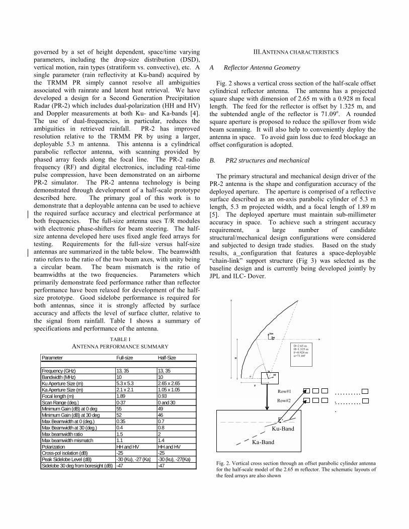
governed by a set of height dependent, space/time varying parameters, including the drop-size distribution (DSD), vertical motion, rain types (stratiform vs. convective), etc. A single parameter (rain reflectivity at Ku-band) acquired by the TRMM PR simply cannot resolve all ambiguities associated with rainrate and latent heat retrieval. We have developed a design for a Second Generation Precipitation Radar (PR-2) which includes dual-polarization (HH and HV) and Doppler measurements at both Ku- and Ka-bands [4]. The use of dual-frequencies, in particular, reduces the ambiguities in retrieved rainfall. PR-2 has improved resolution relative to the TRMM PR by using a larger, deployable 5.3 m antenna. This antenna is a cylindrical parabolic reflector antenna, with scanning provided by phased array feeds along the focal line. The PR-2 radio frequency (RF) and digital electronics, including real-time pulse compression, have been demonstrated on an airborne PR-2 simulator. The PR-2 antenna technology is being demonstrated through development of a half-scale prototype described here. The primary goal of this work is to demonstrate that a deployable antenna can be used to achieve the required surface accuracy and electrical performance at both frequencies. The full-size antenna uses T/R modules with electronic phase-shifters for beam steering. The half-size antenna developed here uses fixed angle feed arrays for testing. Requirements for the full-size versus half-size antennas are summarized in the table below. The beamwidth ratio refers to the ratio of the two beam axes, with unity being a circular beam. The beam mismatch is the ratio of beamwidths at the two frequencies. Parameters which primarily demonstrate feed performance rather than reflector performance have been relaxed for development of the half-size prototype. Good sidelobe performance is required for both antennas, since it is strongly affected by surface accuracy and affects the level of surface clutter, relative to the signal from rainfall. Table I shows a summary of specifications and performance of the antenna.
TABLE I ANTENNA PERFORMANCE SUMMARY
Parameter Full-size Half-Size
Frequency (GHz) 13, 35 13, 35 Bandwidth (MHz) 10 10Ku Aperture Size (m) 5.3 x 5.3 2.65 x 2.65Ka Aperture Size (m) 2.1 x 2.1 1.05 x 1.05Focal length (m) 1.89 0.93Scan Range (deg.) 0-37 0 and 30Minimum Gain (dB) at 0 deg 55 49Minimum Gain (dB) at 30 deg 52 46Max Beamwidth at 0 (deg.) 0.35 0.7Max Beamwidth at 30 (deg.) 0.4 0.8Max beamwidth ratio 1.5 2Max beamwidth mismatch 1.1 1.4Polarization HH and HV HH and HVCross-pol isolation (dB) -25 -25Peak Sidelobe Level (dB) -30 (Ku), -27 (Ka) -30 (ku), -27(Ka)Sidelobe 30 deg from boresight (dB) -47 -47
III.ANTENNA CHARACTERISTICS
A Reflector Antenna Geometry
Fig. 2 shows a vertical cross section of the half-scale offset cylindrical reflector antenna. The antenna has a projected square shape with dimension of 2.65 m with a 0.928 m focal length. The feed for the reflector is offset by 1.325 m, and the subtended angle of the reflector is 71.09o. A rounded square aperture is proposed to reduce the spillover from wide beam scanning. It will also help to conveniently deploy the antenna in space. To avoid gain loss due to feed blockage an offset configuration is adopted.
B. PR2 structures and mechanical
The primary structural and mechanical design driver of the PR-2 antenna is the shape and configuration accuracy of the deployed aperture. The aperture is comprised of a reflective surface described as an on-axis parabolic cylinder of 5.3 m length, 5.3 m projected width, and a focal length of 1.89 m [5]. The deployed aperture must maintain sub-millimeter accuracy in space. To achieve such a stringent accuracy requirement, a large number of candidate structural/mechanical design configurations were considered and subjected to design trade studies. Based on the study results, a configuration that features a space-deployable �chain-link� support structure (Fig 3) was selected as the baseline design and is currently being developed jointly by JPL and ILC- Dover.
Fig. 2. Vertical cross section through an offset parabolic cylinder antenna for the half-scale model of the 2.65 m reflector. The schematic layouts of the feed arrays are also shown
α
H
F
Freq=13.60 GHzD=5.300 mH=2.700 mF=1.855 mα=72.09 deg.
ZmXm
ZfXf
���.���..
Row#1 Row#2
F
Ka-Band
Ku-Band F
.
D=2.65 m H=1.325 m F=0.928 m α=71.04o
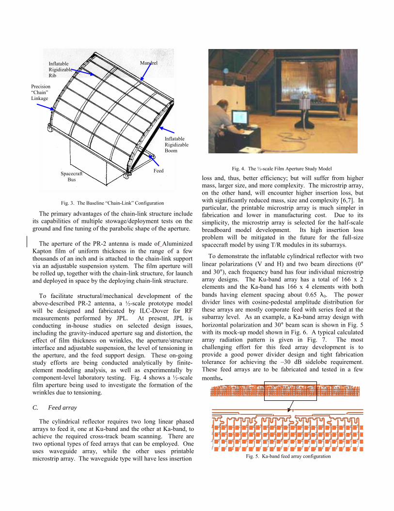
Fig. 3. The Baseline �Chain-Link� Configuration
The primary advantages of the chain-link structure include its capabilities of multiple stowage/deployment tests on the ground and fine tuning of the parabolic shape of the aperture.
The aperture of the PR-2 antenna is made of Aluminized Kapton film of uniform thickness in the range of a few thousands of an inch and is attached to the chain-link support via an adjustable suspension system. The film aperture will be rolled up, together with the chain-link structure, for launch and deployed in space by the deploying chain-link structure.
To facilitate structural/mechanical development of the above-described PR-2 antenna, a ½-scale prototype model will be designed and fabricated by ILC-Dover for RF measurements performed by JPL. At present, JPL is conducting in-house studies on selected design issues, including the gravity-induced aperture sag and distortion, the effect of film thickness on wrinkles, the aperture/structure interface and adjustable suspension, the level of tensioning in the aperture, and the feed support design. These on-going study efforts are being conducted analytically by finite-element modeling analysis, as well as experimentally by component-level laboratory testing. Fig. 4 shows a ½-scale film aperture being used to investigate the formation of the wrinkles due to tensioning.
C. Feed array
The cylindrical reflector requires two long linear phased arrays to feed it, one at Ku-band and the other at Ka-band, to achieve the required cross-track beam scanning. There are two optional types of feed arrays that can be employed. One uses waveguide array, while the other uses printable microstrip array. The waveguide type will have less insertion
Fig. 4. The ½-scale Film Aperture Study Model
loss and, thus, better efficiency; but will suffer from higher mass, larger size, and more complexity. The microstrip array, on the other hand, will encounter higher insertion loss, but with significantly reduced mass, size and complexity [6,7]. In particular, the printable microstrip array is much simpler in fabrication and lower in manufacturing cost. Due to its simplicity, the microstrip array is selected for the half-scale breadboard model development. Its high insertion loss problem will be mitigated in the future for the full-size spacecraft model by using T/R modules in its subarrays.
To demonstrate the inflatable cylindrical reflector with two linear polarizations (V and H) and two beam directions (0° and 30°), each frequency band has four individual microstrip array designs. The Ku-band array has a total of 166 x 2 elements and the Ka-band has 166 x 4 elements with both bands having element spacing about 0.65 λ0. The power divider lines with cosine-pedestal amplitude distribution for these arrays are mostly corporate feed with series feed at the subarray level. As an example, a Ka-band array design with horizontal polarization and 30° beam scan is shown in Fig. 5 with its mock-up model shown in Fig. 6. A typical calculated array radiation pattern is given in Fig. 7. The most challenging effort for this feed array development is to provide a good power divider design and tight fabrication tolerance for achieving the �30 dB sidelobe requirement. These feed arrays are to be fabricated and tested in a few months.
Fig. 5. Ka-band feed array configuration
Mandrel
Spacecraft Bus
Inflatable Rigidizable Boom
Feed
Precision �Chain� Linkage
Inflatable Rigidizable Rib

Fig. 6. Photo of mock-up model for Ka-band feed array
−90.0 −60.0 −30.0 0.0 30.0 60.0 90.0θ (Degrees)
−50.0
−40.0
−30.0
−20.0
−10.0
0.0
10.0
20.0
30.0
40.0
50.0
Direc
tivity
(dB)
Feed PatternF=35GHz,AF[N=664,qx=0.8,qy=1.25],dx=0.75λ,dy=0.63λ
(φ=0o)
(φ=90o)
Fig. 7. Calculated feed array patterns
To verify the performance of patch elements, a cell of array has been fabricated. Fig. 8 shows the fabricated elements. The simulated and measured result of reflection coefficients are demonstrated in Fig. 9.
(a)
(b)
Fig. 8. Fabricated patch elements (a) Ku-band (b) Ka-band.
10 10.5 11 11.5 12 12.5 13 13.5 14 14.5 15-35
-30
-25
-20
-15
-10
-5
0
Frequency (GHz)
S11
(dB
)
Ku-Band (H-pol)
Measured Simulated
(b)
Fig. 9. Measured Reflection coefficient of patch elements (a)Ku-band (b)Ka-band
(a)

IV. PARAMETRIC STUDIES ON LINEAR ARRAY FEED
To illuminate the cylindrical surface most effectively, two dual-polarized linear array feeds are used as shown in Fig. 2. The length of the feed array at Ku-band is equal to the dimension of the reflector. To obtain the same beamwidth in Ka-band, the length of the array should be scaled by the frequency ratio (13.6/35). Therefore, the effective illumination area would be about (1/2.6) of the actual reflector. Also, a large number of elements in each row will cause a high side lobe level. To fulfill the side lobe specification a pedestal height of 25 dB at Ku-band and 22 dB at Ka-band is adopted as array amplitude taper. To minimize the number of array elements in each row, the element spacing (d) has to be maximized. However, increasing the element spacing would create a grating lobe. In general, the parameters that describe the array performance are the element spacing, number of elements, and the excitation coefficient distribution.
One of the most important properties of this antenna is to have a wide angle scan, and the grating lobe problem is more critical for the scanning case. To avoid a grating lobe in the scanning plan, an array spacing of d=0.63λ is adopted. To find the number of rows for the array in each frequency, simulation has been performed. The results show that placing two rows at Ku-band meets the specification of the problem. One of the most important requirements of this problem is to have the performance of the antenna in two frequency bands be as similar as possible. At Ka Band operation, it is expected the situation is worse because the beam width is proportional to the wavelength. In the H-plane this problem can be solved by scaling the length of the feed by the frequency ratio but in the E-plane it seems that two rows won�t be sufficient to get the proper beam width close to Ku Band. The simulation results demonstrated that four rows tapering 3-dB in the E-plane give an acceptable pattern. Also, the beam width can be controlled by changing the array element spacing in E-plane. Increasing the element spacing causes the antenna pattern to get broader. This is because the far field pattern is the Fourier transform of the current on the reflector. If a linear array is used to feed a reflector, the array�s main beam and its side lobes together will generate a sinc function surface current in the plane containing the parabolic curvature. This reflector surface current when Fourier transformed should form a pulse like far field pattern. Increasing the element spacing causes the sinc function to be narrower and therefore the main lobe of the far field pattern gets broader. Fig. 10 shows the far-field patterns of the reflector illuminated by designed feed array for both frequency bands.
V. BEAM SCANNING
As previously discussed, the main reason to choose a cylindrical antenna for this application is to get the capability to, in one plane, scan the beam of the antenna pattern in a wide range. This scanning is achieved by using a phased-array line feed. The maximum angle of scanning depends on the pattern of the reflector. The maximum practical value in this case is about 37o. Problems that must be investigated in the scanning case are: the beam in the scanning plane broadens in one dimension while shrinking in the other plane. This will be more critical in the Ka-Band frequency. Gain decreases as the beam gets broader. The level of cross polarization also increases with a larger scanning angle. The goal is to have a similar pattern over the full range which antenna can scan. According to geometrical specification, the maximum scanning angle value is 37o. The simulation results show that the far-field patterns are acceptable until 30o. After that, the performance degrades significantly due to spillover and path loss. This problem is more critical in Ku band because the reflector is fully illuminated. Therefore, to achieve the best performance a maximum angle of 30o is adopted. Fig. 11 and 12 show the current distribution and pattern at Ku and Ka bands at 30o scan angle.

Fig. 12. Current distribution and far field patterns of the reflector antenna operating at Ka-band for scanning angle=30o
(a)
(b)
−4.0 −3.0 −2.0 −1.0 0.0 1.0 2.0 3.0 4.0θ (Degrees)
0.0
10.0
20.0
30.0
40.0
50.0
60.0
Dire
ctivit
y (dB
)
Pattern=13.6GHz,PA[D=2.65m,F=0.928m,H=1.325m],AF[N=382,qx=0.8,qy=1.25],BT=30
o
CoPol (φ=0o)
XPol (φ=0o)
CoPol (φ=90o)
XPol (φ=90o)
E-planeH-plane
E-plane(X-pol)H-plane(X-pol)
Fig. 11. Current distribution and far field patterns of the reflector antenna operating at Ku band for scanning angle=30o.
(a)
(a)
−4.0 −3.0 −2.0 −1.0 0.0 1.0 2.0 3.0 4.0θ (Degrees)
0.0
10.0
20.0
30.0
40.0
50.0
60.0
Direc
tivity
(dB)
PatternF=13.6GHz,PA[D=2.65m,F=0.928m,H=1.325m],AF[N=382,qx=0.8,qy=1.25]
CoPol (φ=0o)
CoPol (φ=90o)E-plane
H-plane
−4.0 −3.0 −2.0 −1.0 0.0 1.0 2.0 3.0 4.0θ (Degrees)
0.0
10.0
20.0
30.0
40.0
50.0
60.0
Direc
tivity
(dB)
PatternF=35GHz,PA[D=2.65m,F=0.928m,H=1.325m],AF[N=664,qx=0.8,qy=1.25]
CoPol (φ=0o)
CoPol (φ=90o)
E-planeH-plane
(b)
Fig. 10. Far-field patterns of the reflector antenna for no scan case (a) Ku-band (b) Ka-band.
−4.0 −3.0 −2.0 −1.0 0.0 1.0 2.0 3.0 4.0θ (Degrees)
0.0
10.0
20.0
30.0
40.0
50.0
60.0
Direc
tivity
(dB)
Pattern=35GHz,PA[D=2.65m,F=0.928m,H=1.325m],AF[N=664,qx=0.8,qy=1.25],BT=30
o
CoPol (φ=0o)
XPol (φ=0o)
CoPol (φ=90o)
XPol (φ=90o)
E-planeH-plane
E-plane(X-pol)
(b)

ACKNOWLEDGMENT
The research described in this paper was carried out by the Jet Propulsion Laboratory, California Institute of Technology, under contract with the National Aeronautics and Space Administration. ILC Dover has made valuable contributions under contract with JPL, and California State University has provided support through students in their Mechanical Engineering Department.
REFERENCES
[1] Z. S. Haddad, E. Im, and S. L. Duran, �Intrinsic ambiguities in the retrieval of rain rates from radar returns at attenuating wavelengths,� J. Appl. Meteor. Vol. 34, pp. 2667-2697, 1995.
[2] R. Meneghini, H. Kumagai, J. R. Wang, T. Iguchi, and T.kozu, �Microphysical retrievals over stratiform rain using measurements from an airborne dual-wavelength radar-radiometer,� IEEE Trans. Geosci. Remote Sens., vol. 35, pp. 487-506, 1997.
[3] T. Kozu, and Coauthers, �Development of precipitation radar onboard the Tropical Rainfall Measuring Mission (TRMM) satellite,� IEEE Trans. Geosci. Remote Sens., vol. 39, pp. 102-116, 2001.
[4] G. A. Sadowy, A. C. berkun, W. Chun, E. Im, and S. L. Duran, �Development of an advanced airborne precipitation radar,� Microwave J. vol.46, no. 1, pp. 84-98, January 2003.
[5] J. Lin, G. Sapna, S. Scarborough, and B. Lopez, �Advanced precipitation radar antenna-singly curved parabolic antenna reflector development,� Proceeding of the 44th AIAA/ASME/ASCE/AHS/ASC Structures, Structural Dynamics and materials Conference, Norfolk, VA, 2003.
[6] J. Huang, �Microstrip antenna developments at JPL,� IEEE Antennas & Propag. Magazine, vol. 33, pp. 33-41, June 1991.
[7] J. Huang, �A parallel-serial-fed microstrip array high efficiency and low cross-polarization,� Microwave and Optical Technology letters, vol.5, pp. 230-233, May 1992.