advanced plasma and laser science - kenichi...
TRANSCRIPT

Advanced Plasma and Laser Science (Kenichi ISHIKAWA) for internal use only (Univ. of Tokyo)
Kenichi Ishikawa (石川顕一)http://ishiken.free.fr/english/[email protected]
Advanced Plasma and Laser Scienceプラズマ・レーザー特論E
4. High-harmonic generation高次高調波発生
1

石川顕一
Advanced Plasma and Laser Science (Kenichi ISHIKAWA) for internal use only (Univ. of Tokyo)
2
HARMONIC GENERATION高調波発生
€
ω
€
ω
€
ω
crystal, gas
Material response is linear in light intensity
:3次高調波(3rd harmonic)
frequency conversion
€
D = ε0E +P
€
P = ε0 χ(1)E + χ (2)E2 + χ (3)E 3 +![ ]
線形分極 linear polarization 非線形分極 nonlinear
€
∇×∇×E = −µ0∂2D∂t2
Linear optical effect
Nonlinear optical effect
Nonlinear material response�, 2�, 3�, 4�, 5�, · · ·
2�:2次高調波(2nd harmonic)3�
.....
Process whereby integer multiples of the original light’s frequency (fundamental frequency) are generated.
線形光学効果
非線形光学効果
結晶等
結晶等
波長変換物質の応答が、入射光強度に非線形に依存

石川顕一
Advanced Plasma and Laser Science (Kenichi ISHIKAWA) for internal use only (Univ. of Tokyo)
Even-order components vanish for a medium with inversion symmetry
3
E
P(E)
-E
P(-E) = -P(E)
P (E) = �0��(1)E + �(2)E2 + �(3)E3 + �(4)E4 + · · ·
�
P (�E) = �0���(1)E + �(2)E2 � �(3)E3 + �(4)E4 � · · ·
�
�P (E) = �0���(1)E � �(2)E2 � �(3)E3 � �(4)E4 � · · ·
�
�(2) = 0,�(4) = 0, · · ·
反転対称な物質では、偶数次はゼロ

石川顕一
Advanced Plasma and Laser Science (Kenichi ISHIKAWA) for internal use only (Univ. of Tokyo)
摂動論的高調波発生PERTURBATIVE HARMONIC GENERATION
次数が高くなるほど、発生効率は減少。
基底状態
電離
€
!ω
€
!ω
€
!ω仮想準位
€
3!ω
3次高調波発生の概念図Ionization
Virtual level
Ground state
4
MTHG =�
h,i,f
��3 · D1h�1 · Dhi�1 · Dij�1 · Dj1
(3�1 � �h)(2�1 � �i)(�1 � �j)
+�1 · D1h�3 · Dhi�1 · Dij�1 · Dj1
(��1 � �h)(2�1 � �i)(�1 � �j)
+�1 · D1h�1 · Dhi�3 · Dij�1 · Dj1
(��1 � �h)(�2�1 � �i)(��1 � �j)
+�1 · D1h�1 · Dhi�1 · Dij�3 · Dj1
(��1 � �h)(�2�1 � �i)(�3�1 � �j)
遷移行列要素Transition matrix element3rd harmonic
order ↑ efficiency ↓

石川顕一
Advanced Plasma and Laser Science (Kenichi ISHIKAWA) for internal use only (Univ. of Tokyo)
摂動論的高調波発生(PERTURBATIVE HARMONIC GENERATION)
基底状態
電離
€
!ω
€
!ω
€
!ω仮想準位
€
3!ω
基底状態
電離
€
!ω
€
!ω
€
!ω
仮想準位
€
5!ω
€
!ω
€
!ω
3次高調波 5次高調波
5
3rd harmonic 5th harmonic
Ionization Ionization
Virtual levelVirtual level
Ground state Ground state
次数が高くなるほど、発生効率は減少。
order ↑ efficiency ↓

石川顕一
Advanced Plasma and Laser Science (Kenichi ISHIKAWA) for internal use only (Univ. of Tokyo)
高次高調波発生HIGH-HARMONIC GENERATION (HHG)
新しい極端紫外・軟エックス線光源として注目される。New extreme ultraviolet (XUV) and soft X-ray source
6
discovered in 1987
OZSF$:$@E< O]/khHd7<;3=>
ZF$:$KG-/YQJQ��������-0"'O]OUh(*MN,1#
mfP.OUh/<C9>E
���������� ���������!����� ���������� ���������
BD>$6=>5A
! BD>$ %\[/][*jZS-g^&! 6=>5A %XO][/g^&
nW_P.i`edV-0bR-+.)TcIT/ML
inW_P.i`edV/lNkhH"O4?E8$"2>a
Intense laser pulse gas jet harmonics of high orders
Highly nonlinear optical process in which the frequency of laser light is converted into its integer multiples. Harmonics of very high orders are generated.

石川顕一
Advanced Plasma and Laser Science (Kenichi ISHIKAWA) for internal use only (Univ. of Tokyo)
HARMONIC SPECTRUM 高調波スペクトルHow high orders?
Wahlström et al., Phys. Rev. A 48, 4709 (1993)
1015 W/cm2
was raised up to 26 mJ, a maximal output energy exceeding7 mJ was achieved at the signal wavelength near 1.4 !m.
Temporal characterization of amplified OPA pulses wasperformed using a single-shot autocorrelation !AC" tech-nique. A typical AC trace is shown in the inset of Fig. 2.Assuming a Gaussian pulse shape, the pulse width of 1.4 !mpulse was evaluated to be 40 fs in full width at half maxi-mum !FWHM", the energy of which corresponds to the redfilled circles in Fig. 3. The solid red line depicts the Fourier-transform-limited AC trace obtained from the amplified OPAspectrum. The measured pulse width was almost transformlimited and the signal pulse width was shorter than 65 fsover the entire tuning range.
Using the developed high-energy 1.4 !m OPA pulses,we have performed a proof-of-principle experiment on softx-ray harmonic generation from an Ar gas target under anonionized medium condition to exhibit the performance ofour developed IR source. The 1.4 !m IR pulses were fo-cused with f =250 mm CaF2 lens and delivered into the tar-get vacuum chamber through a thin CaF2 window. The Argas target was supplied by a 2 mm synchronized gas jet op-erating at 10 Hz. We used an imaging spectrometer set530 mm away from the Ar gas target to measure the spec-trograph of the HH beam. The blue profile in Fig. 4 showsthe measured HH spectrum of Ar driven by a 1.4 !m pulsewith a backing pressure of 10 atm. The focusing intensitywas fixed to be 1.5"1014 W /cm2 at the interaction region inorder to use a neutral Ar gas condition. Thus, the pump en-ergy of the 1.4 !m pulse was set at 2 mJ with a beam diam-eter of 5 mm. We have generated 105 eV harmonics in theneutral Ar gas condition. We found an intensity minimum ataround 50 eV in Ar spectrum. This minimum point matchesclosely the minimum observed in the photon ionization crosssection of Ar due to the Cooper minimum.18 As shown in theinset of Fig. 4, the almost perfect Gaussian profile of the HHsuggests that there is no density disturbance due to ionizationin the interaction region7. The white profile in the inset indi-cates the far-field spatial profile of a 90 eV harmonic beam.The output beam divergence was measured to be #5 mradFWHM. This good beam quality indicates that a phase
matching condition would be substantially satisfied on thepropagation axis of the pump pulse. The red profile showsthe Ar harmonic spectrum driven by a 0.8 !m pulse of whichcutoff energy was measured to be approximately 48 eV. HHspectrum driven by a 1.4 !m pulse was roughly two ordermagnitudes lower than that of driven by a 0.8 !m pulse. Themeasured HH spectrum driven by a 1.4 !m pulse shows asignificant cutoff extension compared with that obtained withthe 0.8 !m driving field. This result reveals that the 1.4 !mfield generates photons having approximately two timeshigher energy than the 0.8 !m field with the same intensity.This photon energy’s difference is in good agreement with apredicted value from the cutoff formula.
In conclusion, we have developed a high-energy IRsources based on OPA to generate higher photon energy har-monic beams. Output energy exceeding 7 mJ with 40 fspulse width was achieved at a signal wavelength near1.4 !m. Total output energy of 12 mJ was recorded with#45% conversion efficiency. In addition, the measured ArHH spectrum driven by a 1.4 !m shows a significant cutoffextension exceeding 100 eV while the harmonic spatial pro-file is almost perfectly maintained. Our developed IR sourceis attractive not only for extending the HHG energy towardthe kiloelectronvolts region but also for examining the en-ergy scaling of HHG under the phase matching condition.7
1M. Hentschel, R. Kienberger, C. Spielmann, G. A. Reider, N. Milosevic,T. Brabec, P. Corkum, U. Heinzmanns, M. Dreschers, and F. Krausz, Na-ture !London" 414, 509 !2001".
2T. Sekikawa, A. Kosuge, T. Kanai, and S. Watanabe, Nature !London"432, 605 !2004".
3G. Sansone, E. Benedetti, F. Calegari, C. Vozzi, L. Avaldi, R. Flammini, L.Poletto, P. Villoresi, C. Altucci, R. Velotta, S. Stagira, S. D. Silvestri, andM. Nisoli, Science 314, 443 !2006".
4P. Tzallas, D. Charalambidis, N. A. Papadogiannis, K. Witte, and G. D.Tsakiris, Nature !London" 426, 267 !2003".
5Y. Nabekawa, T. Shimizu, T. Okino, K. Furusawa, H. Hasegawa, K. Ya-manouchi, and K. Midorikawa, Phys. Rev. Lett. 96, 083901 !2006".
6Y. Nabekawa, H. Hasegawa, E. J. Takahashi, and K. Midorikawa, Phys.Rev. Lett. 94, 043001 !2005".
7E. Takahashi, Y. Nabekawa, T. Otsuka, M. Obara, and K. Midorikawa,Phys. Rev. A 66, 021802 !2002".
8E. Takahashi, N. Nabekawa, and K. Midorikawa, Opt. Lett. 27, 1920!2002".
9P. B. Corkum, Phys. Rev. Lett. 71, 1994 !1993".10V. S. Yakovlev, M. Ivanov, and F. Krausz, Opt. Express 15, 15351 !2007".11E. Constant, D. Garzella, P. Breger, M. Mevel, C. Dorrer, C. L. Blanc, F.
Salin, and P. Agostini, Phys. Rev. Lett. 82, 1668 !1999".12J. Tate, T. Auguste, H. G. Muller, P. Salieres, P. Agostini, and L. F. Di-
Mauro, Phys. Rev. Lett. 98, 013901 !2007".13P. Colosimo, G. Doumy, C. I. Blaga, J. Wheeler, C. Hauri, F. Catoire, J.
Tate, R. Chirla, A. M. March, G. G. Paulus, H. G. Muller, P. Agostini, andL. F. DiMauro, Nat. Phys. 4, 386 !2008".
14C. P. Hauri, R. B. Lopez-Martens, C. I. Blaga, K. D. Schultz, J. Cryan, R.Chirla, P. Colosimo, G. Doumy, A. M. March, C. Roedig, E. Sistrunk, J.Tate, J. Wheeler, L. F. DiMauro, and E. P. Power, Opt. Lett. 32, 868!2007".
15C. Vozzi, F. Calegari, E. Benedetti, S. Gasilov, G. Sansone, G. Cerullo, M.Nisoli, S. D. Silvestri, and S. Stagira, Opt. Lett. 32, 2957 !2007".
16T. Fuji, N. Ishii, C. Y. Teisset, X. Gu, T. Metzger, A. Baltuska, N. Forget,D. Kaplan, A. Galvanauskas, and F. Krausz, Opt. Lett. 31, 1103 !2006".
17M. Nisoli, S. D. Silvestri, V. Magni, O. Svelto, R. Danielius, A. Piskars-kas, G. Valiulis, and A. Varanavicius, Opt. Lett. 19, 1973 !1994".
18J. A. R. Samson and W. C. Stolte, J. Electron Spectrosc. Relat. Phenom.123, 265 !2002".
FIG. 4. !Color online" Experimentally obtained harmonic spectra in Ar. Redand blue profile depict the spectra with #0=0.8 !m pump and #0=1.4 !mpump, respectively. Both HH spectra are normalized to the peak intensity.The laser focused intensity is adjusted to generate HH under a neutral con-dition for both wavelengths. The inset shows a measured two dimensionalharmonic spectrum image driven by 1.4 !m pump.
041111-3 Takahashi et al. Appl. Phys. Lett. 93, 041111 !2008"
Downloaded 04 Sep 2008 to 134.160.214.76. Redistribution subject to AIP license or copyright; see http://apl.aip.org/apl/copyright.jsp
Takahashi et al., Appl. Phys. Lett. 93, 041111 (2008)
800 nm, 1.6×10¹⁴ W/cm2
10-8
10-7
10-6
10-5
10-4
10-3
10-2
10-1
100
101
102
Harm
onic
inte
nsity (
arb
. unit)
50403020100
Harmonic order
800÷31= 26 nm
Only odd orders 奇数次のみ
7
gas is a medium of inversion symmetry
TDSE Simulation
期待媒質は反転対称

石川顕一
Advanced Plasma and Laser Science (Kenichi ISHIKAWA) for internal use only (Univ. of Tokyo)
8
Even up to 1.6 keV, > 5000 ordersalmost x-ray!
a new type of laser-‐‑‒based radiation sourceレーザーをベースにした新しいタイプの放射線源
Popmintchev et al., Science 336, 1287 (2012)

石川顕一
Advanced Plasma and Laser Science (Kenichi ISHIKAWA) for internal use only (Univ. of Tokyo)
Wahlström et al., Phys. Rev. A 48, 4709 (1993)
1015 W/cm2 TDSE Simulation
プラトー(plateau):Efficiency does NOT decrease with increasing harmonic order. 次数が上がっても強度が落ちない。
カットオフ(cutoff):Maximum energy of harmonic photons
摂動論的には解釈できない
plateau
cutoffplateau
cutoff
ポンデロモーティブエネルギーUp(eV) =
e2E20
4m�2= 9.3� 10�14I(W/cm2)�2(µm)
800 nm, 1.6×10¹⁴ W/cm2
9
Ec � Ip + 3.17Up
10-8
10-7
10-6
10-5
10-4
10-3
10-2
10-1
100
101
102
Harm
onic
inte
nsity (
arb
. unit)
50403020100
Harmonic order
Plateau and cutoff プラトーとカットオフ- remarkable feature of high-harmonic generation -
ponderomotive energyThese features cannot be understood as perturbative harmonic generation.

石川顕一
Advanced Plasma and Laser Science (Kenichi ISHIKAWA) for internal use only (Univ. of Tokyo)
高次高調波発生のメカニズム3ステップモデル 3-STEP MODEL
Paul B. Corkum, Phys. Rev. Lett. 71, 1994 (1993)
10
K. C. Kulander et al., in Super-Intense Laser-Atom Physics, NATO ASI Ser. B, Vol. 316, p. 95 (1993)
Paul B. Corkum
→
tunneling ionization
recombination
photon emission (HHG)
Laser field レーザー電場
Semiclassical electron motion
electron
E(t) = E0 cos �t
トンネル電離 電場中の古典的加速
再結合
発光(高次高調波)

石川顕一
Advanced Plasma and Laser Science (Kenichi ISHIKAWA) for internal use only (Univ. of Tokyo)
3-STEP MODEL OF HHG高次高調波発生の3ステップモデル
Ekin = 2Up(sinφ − sinφ0)2
再衝突
11
時刻 でイオン化。原点に初速ゼロで出現t0
mz = �eE0 cos �t z(t0) = 0 z(t0) = 0
Normalization 規格化 �0 = �t0� = �t
z =E0
�2[(cos �� cos �0) + (�� �0) sin�0]
Ionization at with vanishing initial velocity at origint = t0
Recombination at z = 0φ = φret(φ0) , which satisfies
→
tunneling ionization
recombination
photon emission (HHG)
Laser field レーザー電場
Semiclassical electron motion
electron
E(t) = E0 cos �t
トンネル電離
電場中の古典的加速
再結合
発光(高次高調波)

石川顕一
Advanced Plasma and Laser Science (Kenichi ISHIKAWA) for internal use only (Univ. of Tokyo)
TIME (PHASE) OF RECOMBINATION再衝突時刻
350
300
250
200
150
100
50
0
Phas
e of
reco
mbi
natio
n (p
hi_r
)
150100500Phase of electron release (phi0)
12
z = 0
(cos �)�|�0 =cos �ret � cos �0
�ret � �0
(cos �ret � cos �0) + (�ret � �0) sin�0 = 0
-1.0
-0.5
0.0
0.5
1.0
36032028024020016012080400
phi (degree) �ret�0
イオン化時刻と再衝突時刻の関係
の場合再結合できない
�
2< �0 < �
no recombination for
phase of ionization vs phase of recombination

石川顕一
Advanced Plasma and Laser Science (Kenichi ISHIKAWA) for internal use only (Univ. of Tokyo)
Simple explanation of the cut-off lawカットオフ則のシンプルな説明
3
2
1
0Ele
ctr
on k
inetic e
nerg
y (
in U
p)
360270180900
Phase (degrees)
-1
0
1
Fie
ld (in
E0 )
ionization recombination
short
lon
g
short
lon
g
field
同じ高調波次数(光子エネルギー)に対応するイオン化時刻と再結合時刻のペアは2つある。
short trajectorylong trajectory
13
Ec = Ip + 3.17Up
再結合時の運動エネルギーの最大値
cut-off カットオフ3.17Up
There is the maximum kinetic energy which is classically allowed.
There are two pairs of ionization and recombination times which contribute to the same harmonic energy.

石川顕一
Advanced Plasma and Laser Science (Kenichi ISHIKAWA) for internal use only (Univ. of Tokyo)
WHY DO HARMONIC SPECTRA CONSIST OF DISCRETE PEAKS? なぜ、高次高調波スペクトルは離散的なのか?
FIG. 4. !Color online" Experimentally obtained harmonic spectra in Ar. Red
トンネル電離と高調波の発生は、レーザーの半周期ごとに起こる。
14
10-8
10-7
10-6
10-5
10-4
10-3
10-2
10-1
100
101
102
Harm
onic
inte
nsity (
arb
. unit)
50403020100
Harmonic order
Takahashi et al., Appl. Phys. Lett. 93, 041111 (2008)
→
tunneling ionization
recombination
photon emission (HHG)
Laser field レーザー電場
Semiclassical electron motion
electron
E(t) = E0 cos �t
トンネル電離 電場中の古典的加速
再結合
発光(高次高調波)
This is repeated every half cycle with an alternating phase

石川顕一
Advanced Plasma and Laser Science (Kenichi ISHIKAWA) for internal use only (Univ. of Tokyo)
the emission of a pulse of a high-order harmonic field everyhalf-cycle period. In this model, the trajectory of theelectron, moving along the direction of the electric fieldof the fundamental laser, determines the phase of theemitted harmonic field. Therefore, our finding of the!-flipped phase in the attosecond pulse train verifies thatharmonic pulses are certainly from electrons detachedfrom opposite sides at every half-cycle period of the fun-damental laser field.
Note that the clear observation of phase locking in theactual experiment is due to the small number of interfer-ence fringes emerging from near single-cycle pulses in theAPT. We estimated the duration of the pulse by comparingthe calculated results of the interferometric autocorrelationof the harmonic fields with group-delay dispersion (GDD)and its Fourier transform to the measured results. Details ofthis calculation will be reported elsewhere. We plot thecalculated autocorrelation trace and its magnitude squareof Fourier amplitude as solid blue curves in Figs. 2(a) and2(b), respectively. Setting the GDD to 1:3! 10"32 #s2$,which is the measured numeric value with the separateexperiment [11], there is fairly good agreement betweenthe experimental observation and the calculated result ofboth autocorrelation and Fourier transform. The increasedGDD to 2:0! 10"32 #s2$ reduced the height of the enve-lope with the remaining interference fringe in the autocor-relation so that the intensity at 2"f in the Fourier transformis almost equal to that at 11"f. Therefore, 1:3! 10"32 #s2$is the reasonable GDD in practice, although we might takeinto account the intrinsic response of N2 to two-photonabsorption, as was mentioned in Refs. [27,28] for rare-gasatoms, in order to determine GDD in more detail.
The envelope and optical field of the attosecond pulsetrain, evaluated from the measured intensity ratio of theharmonic fields from the 9th to 19th orders and the esti-mated GDD, are shown in Fig. 3. The duration of the pulseenvelope is 320 attoseconds in full width at half maximum,which corresponds to only an %1:3-cycle period of theprincipal carrier frequency of the 11th harmonic field.Thus, we can clearly see the relative phase of interferencefringes to pulse envelopes.
In conclusion, we have shown clear evidence of thelocked phase in an attosecond pulse train by interferomet-ric autocorrelation. The detection of fringes that emergedfrom the interference of a pulse sequence in the XUV rangeenables us to determine the phase difference betweenpulses, so that we would obtain the instantaneous shapeof the optical field in the attosecond pulse train by combin-ing this result with those obtained by other techniques formeasuring the chirp [9,11,29] and by using a driving laserfield whose absolute phase is stabilized [1,2]. Thus, anoptical synthesizer of XUV light comes into the realm ofreality.
We thank Dr. E. J. Takahashi at RIKEN for his support ingenerating intense harmonic fields. This study was finan-cially supported by MEXT through a Grant-in-Aid forScientific Research on Priority Areas, for YoungScientists (A) and for Young Scientists (B).
*Electronic address: [email protected][1] A. Baltuska et al., Nature (London) 421, 611 (2003).[2] R. Kienberger et al., Nature (London) 427, 817 (2004).[3] J. Reichelt et al., Opt. Commun. 172, 59 (1999).[4] H. R. Telle et al., Appl. Phys. B 69, 327 (1999).[5] D. H. Jones et al., Science 288, 635 (2000).[6] C. Gohle et al., Nature (London) 436, 234 (2005).[7] R. J. Jones et al., Phys. Rev. Lett. 94, 193201 (2005).[8] P. Antoine et al., Phys. Rev. Lett. 77, 1234 (1996).[9] P. M. Paul et al., Science 292, 1689 (2001).
[10] P. Tzallas et al., Nature (London) 426, 267 (2003).[11] Y. Nabekawa et al., Phys. Rev. Lett. 96, 083901 (2006).[12] T. Sekikawa et al., Nature (London) 432, 605 (2004).[13] K. Varju et al., Phys. Rev. Lett. 95, 243901 (2005).[14] E. J. Takahashi et al., Opt. Lett. 27, 1920 (2002).[15] E. Takahashi et al., Phys. Rev. A 68, 023808 (2003).[16] Y. Nabekawa et al., Phys. Rev. Lett. 94, 043001 (2005).[17] H. Hasegawa et al., Laser Phys. 15, 812 (2005).[18] E. J. Takahashi et al., Opt. Lett. 29, 507 (2004).[19] E. J. Takahashi et al., IEEE J. Sel. Top. Quantum Electron.
10, 1315 (2004).[20] K. Hoshina et al., J. Phys. B 39, 813 (2006).[21] T. E. Glover et al., Phys. Rev. Lett. 76, 2468 (1996).[22] E. W. Thulstrup and A. Andersen, J. Phys. B 8, 965 (1975).[23] R. W. Wetmore and R. K. Boyd, J. Phys. Chem. 90, 5540
(1986).[24] In fact, the fringes corresponding to the carrier frequencies
of the harmonic fields in the IAC trace should originatefrom the term ~S&'(&!2&N'1(; 0(~S&'() &!2&N'1(; #(, where themode-resolved correlation amplitude ~S&'(&!2&N'1(; #( wasdefined as Eq. (2) in Ref. [11]. The factor ei&2n'1(!f# in~S&'(&!2&N'1(; #( necessarily yields the odd parity of thefringes to the translation of the delay with &q' 1=2(Tf.
[25] P. B. Corkum, Phys. Rev. Lett. 71, 1994 (1993).[26] M. Lewenstein et al., Phys. Rev. A 49, 2117 (1994).[27] T. Nakajima and S. Watanabe, Phys. Rev. A 70, 043412
(2004).[28] L. A. A. Nikolopoulos et al., Phys. Rev. Lett. 94, 113905
(2005).[29] T. Sekikawa et al., Phys. Rev. Lett. 88, 193902 (2002).
-3 -2 -1 0 1 2 3
time [fs]
FIG. 3 (color online). Estimated intensity profile of the atto-second pulse train (dark-green curve with hatched area) and theoptical field (dark-blue curve).
PRL 97, 153904 (2006) P H Y S I C A L R E V I E W L E T T E R S week ending13 OCTOBER 2006
153904-4
Nabekawa et al., Phys. Rev. Lett. 97, 153904 (2006)
実験的にも観測されている高調波の電場波形の概念図
f(t) = �f(t� �/�0)基本波の奇数倍の周波数成分のみを含む。
15
-2 -1 0 1 2Fundamental optical cycle
harmonic field harmonic intensity fundamental field
laser cycle レーザーの1周期(2.7 fs)
Harmonic electric fieldExperimentally measured
Spectrum only consists of odd harmonics.
石川顕一
Advanced Plasma and Laser Science (Kenichi ISHIKAWA) for internal use only (Univ. of Tokyo)
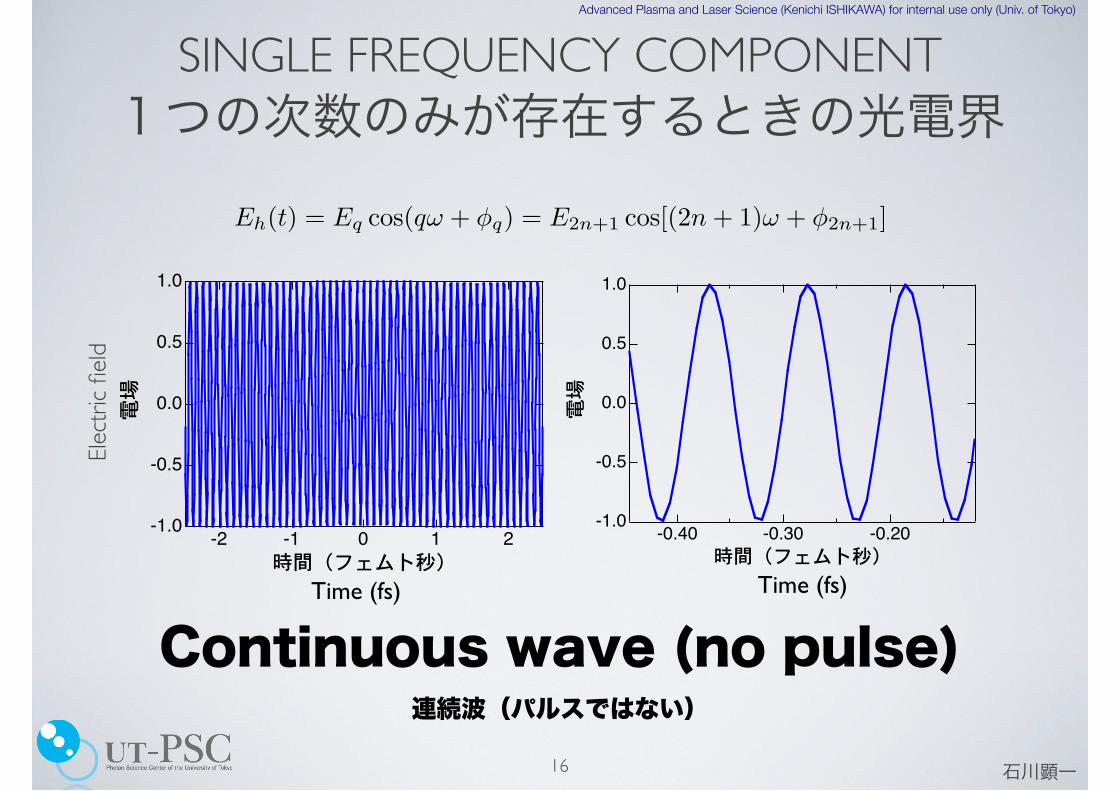
1つの次数のみが存在するときの光電界
16
Eh(t) = Eq cos(qω + φq) = E2n+1 cos[(2n + 1)ω + φ2n+1]
1.0
0.5
0.0
-0.5
-1.0
電場
-2 -1 0 1 2時間(フェムト秒)
1.0
0.5
0.0
-0.5
-1.0
電場
-0.40 -0.30 -0.20時間(フェムト秒)
Continuous wave (no pulse)連続波(パルスではない)
Elect
ric fi
eldSINGLE FREQUENCY COMPONENT
Time (fs) Time (fs)

石川顕一
Advanced Plasma and Laser Science (Kenichi ISHIKAWA) for internal use only (Univ. of Tokyo)
train of repeated pulses
複数の次数(奇数次)が混在するときの光電界
17
Eh(t) =!
q
Eq cos(qω + φq) =!
q
E2n+1 cos[(2n + 1)ω + φ2n+1]
等間隔の周波数成分 等間隔のパルス列
MULTIPLE (ODD) HARMONIC COMPONENTS
• attosecond pulse train (APT)アト秒パルス列になっている
• bursts repeated every half cycle of the fundamental laserパルスの間隔は、基本波の半周期
• adjacent pulses have an opposite phase隣り合うパルスは位相が反転
1.0
0.5
0.0
-0.5
-1.0
電場
-2 -1 0 1 2時間(フェムト秒)Time (fs)
Elec
tric
fiel
d
equispaced frequency components
We don’t need “photons” to understand harmonic generation

石川顕一
Advanced Plasma and Laser Science (Kenichi ISHIKAWA) for internal use only (Univ. of Tokyo)
DISCRETE PEAKS OF ODD HARMONICS CAN BE INTERPRETED IN TWO WAYS.高次高調波の奇数次のみを含む離散的なピークは、二通りに解釈できる。
18
•Integer number of photon energy + inversion symmetry光子エネルギーの整数倍+反転対称性
•Light emission repeated every half cycle (with alternating phase)基本波の半サイクルごとに、反対の位相で光放出

石川顕一
Advanced Plasma and Laser Science (Kenichi ISHIKAWA) for internal use only (Univ. of Tokyo)
次数によって高調波の発生時刻が異なる
19
低次が先に高次が後で発生する。
ポジティブチャープ
350
300
250
200
150
100
Phas
e of
reco
mbi
natio
n (p
hi_r
)
3.02.52.01.51.00.50.0Electron energy (in Up)
short trajectory
Long trajectory
Mairesse et al., Science 302, 1540 (2003)
ショートトラジェクトリーの場合
where !O is the selected spectral bandwidth. The attosecond pulses correspondingto the first trajectory are thus positively chirped (the low orders are emitted beforethe high orders), while those corresponding to the second trajectory exhibit anegative chirp.
Figure 4. XFROGmeasurements [20]. The images on the right and left sides of the figurerepresent the photoelectron signal as a function of the delay between pump and probeand energy of the photoelectron (vertical). On the left, several sidebands with order22, 20, 18, 16, 14 from the top to the bottom obtained for a Fourier-transform-limitedlaser pulse are shown. On the right, the sideband 18 is shown for three fundamentalchirps: bfund ¼ 1:2, 0, "0:8# 1027 s"2. The graph in the middle shows the measured(filled symbols) and simulated (open symbols) chirp rates as a function of order inthe three different fundamental chirp cases (see text). The black straight line is a fit tothe simulated points; the blue and red lines are obtained from the latter by usingequation (7).
0 500 1000 1500 20000
10
20
30
40
Inte
nsity
(ar
b.un
its)
Time (as)
Figure 5. Attosecond pulse train corresponding to the superposition of groups of 5consecutive harmonics generated in neon at 3:8# 1014 Wcm"2: harmonics 25 to 33(red), 35 to 43 (green), 45 to 53 (blue), 55 to 63 (purple). The train correspondingto the full available spectral width (25 to 69) is shown by the yellow-filled curve.Dots represent the absolute value of the laser electric field [21].
Frequency chirp of harmonic and attosecond pulses 387
Ne
測定
理論
Varju et al., J. Mod. Opt. 52, 379 (2005)
3.8×10¹⁴ W/cm2
高調波放出時刻
Time of emission depends on harmonic order
measurement
theory
Positive chirp
Higher-order components emitted later
For the case of short trajectory
Amazing predictive power of the 3-step model!

石川顕一
Advanced Plasma and Laser Science (Kenichi ISHIKAWA) for internal use only (Univ. of Tokyo)
20
350
300
250
200
150
100
Phas
e of
reco
mbi
natio
n (p
hi_r
)
3.02.52.01.51.00.50.0Electron energy (in Up)
short trajectory
Long trajectory
K. L. Ishikawa, “High-harmonic generation” in Advances in Solid-State Lasers, ed. by M. Grishin (INTECH, 2010) 439-464
次数によって高調波の発生時刻が異なるTime of emission depends on harmonic order
TDSE simulation
Positive chirpfor the short trajectory
for the long trajectory
Negative chirp

Advanced Plasma and Laser Science (Kenichi ISHIKAWA) for internal use only (Univ. of Tokyo)
高次高調波発生の量子論
21
Lewenstein et al., Phys. Rev. A 49, 2117 (1994)
Quantum theory of high-harmonic generation
Lewenstein model

石川顕一
Advanced Plasma and Laser Science (Kenichi ISHIKAWA) for internal use only (Univ. of Tokyo)
高強度場近似
22
•励起状態の寄与を無視 The contribution of all the excited bound
states can be neglected.
•連続状態に対する原子のポテンシャルの効果を無視(連続状態を平面波で近似)The effect of the atomic potential on
the motion of the continuum electron can be neglected.
•基底状態の減少を無視 The depletion of the ground state can be
neglected.
Strong-field approximation (SFA)

石川顕一
Advanced Plasma and Laser Science (Kenichi ISHIKAWA) for internal use only (Univ. of Tokyo)
23
双極子モーメント Time-dependent dipole moment
i��(r, t)
�t=
��1
2�2 + V (r) + zE(t)
��(r, t)
x(t) � ��(r, t) | z | �(r, t)�
x(t) = i
� t
��dt�
�d3p d�(p + A(t)) · exp[�iS(p, t, t�)] · E(t�)d(p + A(t�)) + c.c.
= i
� t
��dt�
�d3p ��(r)eiIpt|z|p + A(t)� exp
��i
� t
t�dt��
�[p + A(t��)]2
2
���p + A(t�)|zE(t�)|�(r)eiIpt�� + c.c.
イオン化再結合 レーザー場中での運動
= i
� t
��dt�
�d3p ��(r)eiIpt|z|p + A(t)� exp
��i
� t
t�dt��
�[p + A(t��)]2
2
���p + A(t�)|zE(t�)|�(r)eiIpt�� + c.c.
イオン化再衝突電子波束
遷移双極子行列要素transition dipole半古典的作用積分 S(p, t, t�) =
� t
t�dt��
�[p + A(t��)]2
2+ Ip
�
semiclassical action
recombination motion in the laser field ionization3-step model
ionizationrecolliding electron wave packetDipole moment between the recolliding wave packet and the ground state
再衝突電子波束と基底状態との間の双極子モーメント
transition dipole

石川顕一
Advanced Plasma and Laser Science (Kenichi ISHIKAWA) for internal use only (Univ. of Tokyo)
24
高調波スペクトル=双極子モーメントのフーリエ変換
x(�h) = i
� �
��dt
� t
��dt�
�d3p d�(p + A(t)) · exp[i�ht� iS(p, t, t�)] · E(t�)d(p + A(t�)) + c.c.
5重積分
鞍点解析cf. path integral 経路積分
five-dimensional integral
saddle-point analysis
HARMONIC SPECTRUM= FOURIER TRANSFORM OF DIPOLE MOMENT

石川顕一
Advanced Plasma and Laser Science (Kenichi ISHIKAWA) for internal use only (Univ. of Tokyo)
25
saddle-point analysis (SPA)
➡ physically corresponds to the 3-step model
[p + A(t�)]2
2= �Ip
[p + A(t)]2
2+ Ip = �h
tunneling ionization� t
t�[p + A(t��)]dt�� = 0
harmonic photon energy= kinetic energy at recombination + ionization potential
recombines at the location of ionization
Saddle-point equations
x(�h) =�
s
��
� + i2 (ts � t�s)
�3/2i2��
det S��(t, t�)|sd�(ps + A(ts))
� exp[i�hts � iS(ps, ts, t�s)]E(t�s)d(ps + A(t�s)),
solutions 解 → trajectories トラジェクトリーt’ time of ionizationt time of recombinationトンネル電離
イオン化と再結合の位置が同じ
高調波の光子エネルギー = 再結合時の運動エネルギー + イオン化ポテンシャル
3ステップモデルに物理的に対応

石川顕一
Advanced Plasma and Laser Science (Kenichi ISHIKAWA) for internal use only (Univ. of Tokyo)
Example of saddle-point solutions 鞍点解の例
• 3ステップモデルは、量子力学的なLewensteinモデルのよい近似になっている。→ 3ステップモデルの成功の理由
26
E(t) = E0 cos �t Ar (Ip = 15.7596 eV) 1.6� 1014 W/cm2
破線は3ステップモデルの解
「トンネル時間」に対応すると解釈されている
Ec = 3.17Up + gIp
(g � 1.3)
cutoff カットオフ
の実部(上)と虚部(下)� = �t�� = �t�Real part (top) and imaginary part (bottom) of
dashed lines: 3-step model
interpretted as “tunnling time”
‣ The 3-step model is a good approximation to the quantum-mechanical Lewenstein model → Success of the 3-step model