advanced piping & tubing - siemens plm community piping & tubing ronnie conerly, ... product...
TRANSCRIPT

Restricted © Siemens AG 2015
Advanced Piping & Tubing Ronnie Conerly, Product Manager, Siemens PLM Software

2015-XX-XX
Restricted © Siemens AG 2015
Page 2 Siemens PLM Software
Agenda
• Who am I?
• What you will learn
• Solid Edge Capabilities
• Demonstrations
• Benefits of this topic
• How to Learn More
• Wednesday, 3:00-4:00 PM

2015-XX-XX
Restricted © Siemens AG 2015
Page 3 Siemens PLM Software
Who am I?
Ronnie Conerly Product Manager for Simulation and Equipment Layout Siemens PLM Software • Bachelors degree in Mechanical Engineering – Texas A&M University • 26 years experience in CAD/CAE industry • Worked at NASA’s Marshall Space Flight Center as CAD/CAE consultant • Managed engineering support contracts at MSFC, JSC, and KSC • General Manager for Knight & Hale Game Calls and Carry-Lite Decoys

2015-XX-XX
Restricted © Siemens AG 2015
Page 4 Siemens PLM Software
What you will learn
Need something routed? This presentation introduces how to route: • Pipes • Tubes
• Solid Edge’s assembly application contains multiple environments allowing you to design custom routing features to include in your designs. See how easy it is to route pipe and tube segments
• Available with Solid Edge Premium or separate licenses

2015-XX-XX
Restricted © Siemens AG 2015
Page 5 Siemens PLM Software
Assembly Routing
Solid Edge Assembly has several routing environments with functionality for specific routing applications. These environments include:
• XpresRoute • Piping • Tubing
• Frame • Wire Harness
• All environments have common sketch and curve creations commands to drive the feature creation and editing

2015-XX-XX
Restricted © Siemens AG 2015
Page 6 Siemens PLM Software
Assembly Routing
Plant Layout
Frames Tubes Piping Harness

2015-XX-XX
Restricted © Siemens AG 2015
Page 7 Siemens PLM Software
Existing Path Creation Commands
• All routing environments have 3d Path creation commands
• PathXpres • Line • Arc • Curve • Keypoint Curve • Split Element
• 3D Relationships • 3D Dimensioning • All commands will eventually be replaced by 3D
sketching!

2015-XX-XX
Restricted © Siemens AG 2015
Page 8 Siemens PLM Software
3D Sketching
• Added in ST7 • Available in ALL 3d Modeling environments • Can be used in all routing applications • UI/Functionality similar to 2d sketching but 3D • Can use Peer Edge locate to reference geometry outside the edited subassy • Old commands to be sunsetted in the future

2015-XX-XX
Restricted © Siemens AG 2015
Page 9 Siemens PLM Software
Peer Edge Locate
• Subassembly in-place creation • Piping Subassemblies • Tubing Subassemblies • Wire Harness Subassemblies • Frame Subassemblies
• Hold Shift Key when referencing higher level geometry
• Creates interpart links/references to geometry

2015-XX-XX
Restricted © Siemens AG 2015
Page 10 Siemens PLM Software
Tubing

2015-XX-XX
Restricted © Siemens AG 2015
Page 11 Siemens PLM Software
Tubes
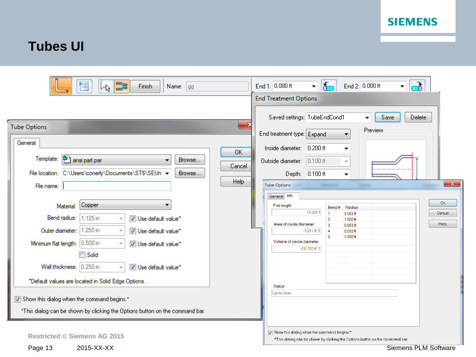
• Tubes are single continuous components driven by 3D paths • Part files created on disc for each tube • Inputs (SE Options controls default inputs or user can override defaults)
• Part Template • File Location • Filename • Material • Bend Radius - Global • Outer Diameter • Minimum Flat Length • Wall Thickness (or Solid)
• Bend Tables/Reports for each tube • New in ST7, Saved Settings • New in ST7, Inter-Part Manager

2015-XX-XX
Restricted © Siemens AG 2015
Page 12 Siemens PLM Software
Tube End Treatment Options
• End Treatment Options
None Expand Flange Reduce Closed
2015-XX-XX
Restricted © Siemens AG 2015
Page 13 Siemens PLM Software
Tubes UI

2015-XX-XX
Restricted © Siemens AG 2015
Page 14 Siemens PLM Software
Fixed Length Flexible Hose
Added in ST7, 3d curves can have fixed length values • Length Value and Edit directional control

2015-XX-XX
Restricted © Siemens AG 2015
Page 15 Siemens PLM Software
Piping
2015-XX-XX
Restricted © Siemens AG 2015
Page 16 Siemens PLM Software
Pipes
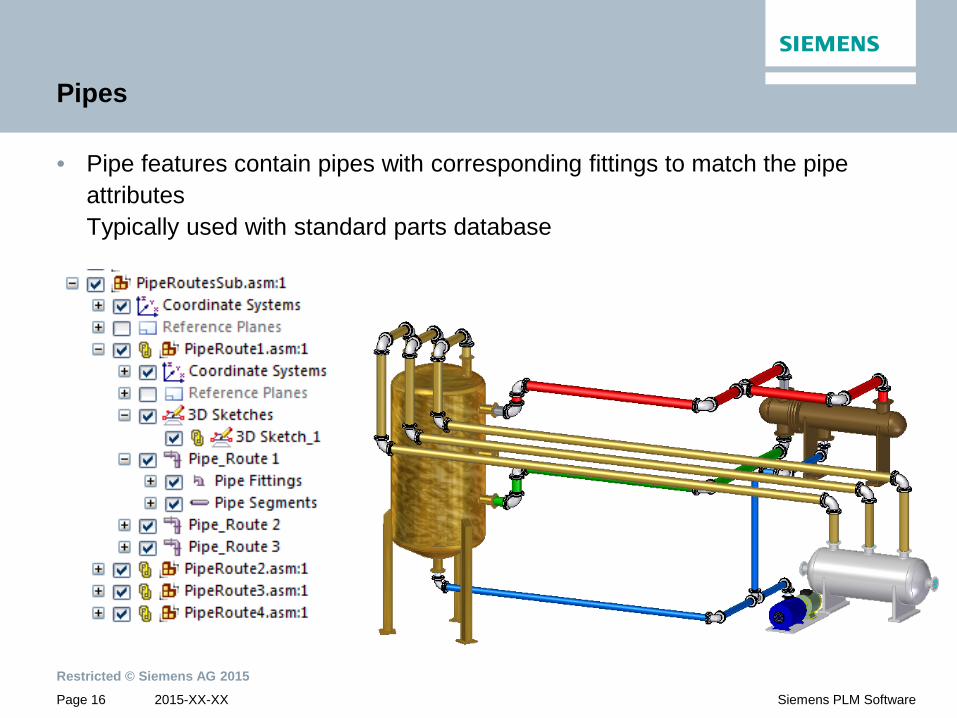
• Pipe features contain pipes with corresponding fittings to match the pipe attributes Typically used with standard parts database

2015-XX-XX
Restricted © Siemens AG 2015
Page 17 Siemens PLM Software
Pipes
For Advanced Piping functionality check out Smap3D from CadPartner www.smap3d.com

2015-XX-XX
Restricted © Siemens AG 2015
Page 18 Siemens PLM Software
Pipe Design Workflow – Piping Route Command – Select Path Step
• ‘Select Path’ step • Select a path to define the piping route
• Specify whether a gradient exists in the path (if
any) and the maximum allowed gradient angle
• Click Accept button once done
2015-XX-XX
Restricted © Siemens AG 2015
Page 19 Siemens PLM Software
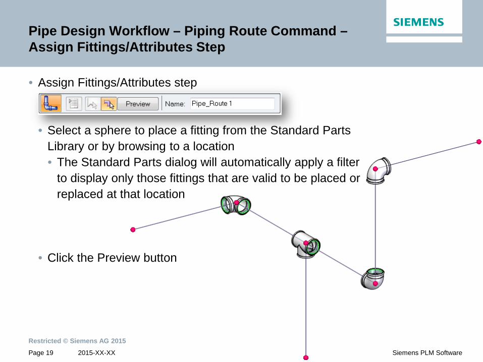
Pipe Design Workflow – Piping Route Command – Assign Fittings/Attributes Step
• Assign Fittings/Attributes step • Select a sphere to place a fitting from the Standard Parts
Library or by browsing to a location • The Standard Parts dialog will automatically apply a filter
to display only those fittings that are valid to be placed or replaced at that location
• Click the Preview button

2015-XX-XX
Restricted © Siemens AG 2015
Page 20 Siemens PLM Software
Pipe Design Workflow – Piping Route Command – Finish Step
• Clicking the Preview button will create the pipes • Pipes embedded in the assembly
• Click the Finish button to complete the piping route

2015-XX-XX
Restricted © Siemens AG 2015
Page 21 Siemens PLM Software
Pipe Edit Workflow – Edit Fitting
• Select a single fitting • Edit Definition • Edit Fitting
• If “Edit Fitting” is selected, the user is presented with options for that fitting
Edit Definition Edit Fitting
Flip Fitting
Replace fitting: Standard Parts Library
Replace fitting: Browse from disk
Penetration Cut Orientation with respect to pipe centerline

2015-XX-XX
Restricted © Siemens AG 2015
Page 22 Siemens PLM Software
Pipe Edit Workflow – Edit Fitting
• If “Edit Definition” is selected, the user can go to “Assign Fittings/Attributes” step and edit multiple fittings by selecting the respective spheres Select these
fittings to edit

2015-XX-XX
Restricted © Siemens AG 2015
Page 23 Siemens PLM Software
Pipe Edit Workflow – Edit Pipe
• Select a single pipe • Edit Definition • Edit Pipe
• If “Edit Pipe” is selected, the user is presented with “Piping Attributes” dialog • Choose pipe from
• Standard Parts Library • Browse from disk
Edit Definition Edit Pipe

2015-XX-XX
Restricted © Siemens AG 2015
Page 24 Siemens PLM Software
Pipe Edit Workflow – Edit Pipe
• If “Edit Definition” is selected, the user can go to “Assign Fittings/Attributes” step and edit multiple pipes by selecting them Select these pipes to edit

2015-XX-XX
Restricted © Siemens AG 2015
Page 25 Siemens PLM Software
Pipe Edit Workflow – Invalid Fittings
• When a piping route is modified to change a pipe diameter or add/subtract a path segment, the fittings that were placed automatically will automatically be replaced
• The fittings that were placed manually will not be replaced automatically
• Solid Edge highlights the flange and displays a warning dialog • Zoom to the problem fitting • Browse the Standard Parts Library • Browse a local folder • Cancel the operation

2015-XX-XX
Restricted © Siemens AG 2015
Page 26 Siemens PLM Software
Pipe Gradient
• Use the “Pipe Gradient” option to build this positive drain right in the pipe path • Notice the path has a 92 degree angle
• In the “Select Path” step, select the “Pipe Gradient” option
• Enter the maximum gradient value to be allowed in this piping route • up to +/- 20 degree maximum

2015-XX-XX
Restricted © Siemens AG 2015
Page 27 Siemens PLM Software
Pipe Classification
• Pipe features contain pipes with corresponding fittings to match the pipe attributes
• Typically used with Piping Library/Standard Parts • Can Browse for Fittings for files on disk
• We deliver with SE a PipeClass.txt file in the Preferences folder. • Contains pipe specification information for querying the database

2015-XX-XX
Restricted © Siemens AG 2015
Page 28 Siemens PLM Software
Piping Utility
• With the capability to place pipes and fittings from a local drive, we also need a tool to create the right coordinate systems and attributes required to define a pipe or a fitting
• This tool can be found under the piping utility folder
• In order for this tool to work, you have to have a Solid Edge file open such as the fitting
• Once the file is open, double-click “PreparePipingComponents.exe”

2015-XX-XX
Restricted © Siemens AG 2015
Page 29 Siemens PLM Software
Piping Utility
• The following dialog presents the options that perform all the tasks necessary to prepare the model for correct positioning in a pipe path
• The first option determines the part type: prepare a fitting or a pipe

2015-XX-XX
Restricted © Siemens AG 2015
Page 30 Siemens PLM Software
Piping Utility
• The next input is to determine the diameter information

2015-XX-XX
Restricted © Siemens AG 2015
Page 31 Siemens PLM Software
Piping Utility
• The final step is to graphically select the two openings in the fitting • It is important to identify the diameter at the depth in which the pipe will fit

2015-XX-XX
Restricted © Siemens AG 2015
Page 32 Siemens PLM Software
Piping Utility
• Notice the coordinate systems are automatically created and added to the PathFinder, as well as the correct variable to the variable table

2015-XX-XX
Restricted © Siemens AG 2015
Page 33 Siemens PLM Software
Contact Information
Ronnie Conerly Product Manager Solid Edge / HSV / Planning
675 Discovery Drive Suite 100 Huntsville, AL 35806
Phone: (256) 705 2608 Fax: (256) 705 2695 Mobile: (256) 656 8567
E-mail: [email protected]
Thank You!