advanced logistics delivery ship (aldv)
TRANSCRIPT

Design Report Advanced Logistics Delivery Ship
(ALDV) VT Total Ship Systems Engineering
ALDV Option 16 Ocean Engineering Design Project
AOE 4065/4066 Fall 2004 – Spring 2005 Virginia Tech Team 2
Morgan Baldwin ___________________________________________ 20549
Aaron Cox ___________________________________________ 20729
Nathan Good – Team Leader ___________________________________________ 20569
Nick Marickovich ___________________________________________ 21068
Travis Smith ___________________________________________ 19603
Ryan Webster ___________________________________________ 22410

ALDV Design – VT Team 2 Page 2
Executive Summary
This report describes the Concept Exploration and
Development of an Advanced Logistics Delivery Ship (ALDV) for the United States Navy. This concept design was completed in a two -semester ship design course at Virginia Tech.
The ALDV requirement is based on the ALDV Mission Need Statement (MNS) and Virginia Tech ALDV Acquisition Decision Memorandum (ADM). ALDV is required to support troops ashore operating from a seabase or shuttle ship using an Advanced Logistics Delivery System (ALDS). ALDS is a ship-launched, over-the-beach, logistics delivery system that uses cargo-filled unmanned gliders and other revolutionary technology. Necessary ALDS support by ALDV includes providing rapid transport of ALDS stores and ammunition, employing automated techniques for assembling the unmanned ALDS gliders, and providing a mechanical launching system for the gliders. ALDV must also support V-22 Ospreys and LAMPS, providing for launch and takeoff, landing, fueling, planning and control. ALDV will operate in sensitive littoral regions, close-in, depend on passive survivability and stealth, with high endurance and low manning.
Concept Exploration trade-off studies and design space exploration are accomplished using a Multi-Objective Genetic Optimization (MOGO) after significant technology research and definition. Objective attributes for this optimization are cost, risk (technology, cost, schedule and performance) and mission effectiveness. The product of this optimization is a series of cost-risk-effectiveness frontiers which are used to select alternative designs and define Operational Requirements based on the customer’s preference for cost, risk and effectiveness.
ALDV Option 16 is a low risk, low cost, knee-in-the-curve trimaran design on the cost-risk-effectiveness frontier. This design was chosen because it provides a sharp increase in effectiveness with a minimal increase in cost at a low risk level based on the MOGO results . ALDV-16 characteristics are listed in the following table. ALDV-16 has a wave-piercing bow to decrease wave resistance and improve high speed performance in high sea states. It has a tumblehome hullform and other stealth technology such as an Advanced Enclosed Mast/Sensor (AEM/S) to reduce radar cross section. ALDV-16 has an ALDS Mission Bay located in the cross-deck for automated glider assembly and a unique Linear Induction Motor (LIM) for mechanical launch of aircraft. It uses other automation technology such as watch standing technologies that include GPS, automated route
planning, electronic charting and navigation (ECDIS), collision avoidance, and electronic log keeping. ALDV-16 also employs automated cargo handling technologies such as conveyor belts, cargo elevators, robotic pickers, and radio frequency identification (RFID).
Concept Development included hullform development and analysis for intact and damage stability, structural finite element analysis, propulsion and power system development and arrangement, general arrangements, machinery arrangements, combat and mission system definition and arrangement, seakeeping analysis, cost and producibility analysis and risk analysis. The final concept design satisfies critical operational requirements in the ORD with additional work required to improve seakeeping, reduce structural weight and lower cost. Ship Characteristic Value
LWL 176 m Beam 28.3 m Draft 4.8 m D10 15.4 m Lightship weight 3119 MT Full load weight 5465 MT Sustained Speed 45.6 knots Endurance Speed 20.0 knots Sprint Range 1477 n m Endurance Range 4687 n m
Propulsion and Power Mechanical drive w/epicyclic gears,
2xMT30 engines, 4x3500kw SSGTGs , 2 x 300SII Kamewa Waterjets
BHP 72000 kW Personnel 45 OMOE (Effectiveness) 0.346 OMOR (Risk) 0.202 Follow Ship Acquisition Cost
$502M
Life -Cycle Cost $635M Combat Systems (Modular and Core)
ALDS, LAMPS/V-22 Refueling Capabilities, CIWS, Degaussing, AN/SLQ -25 NIXIE, A N/SPS-73,
Small Arms/Pyro, 7m RHIB, MK XII AIMS IFF, Combat DF
Provisions Duration 29 Days MEB Mission Duration 5 Days

ALDV Design – VT Team 2 Page 3
Table of Contents
EXECUTIVE SUMMARY .......................................................................................................................................................2
TABLE OF CONTENTS ...........................................................................................................................................................3
1 INTRODUCTION, DESIGN PROCESS AND PLAN ......................................................................................................5
1.1 INTRODUCTION.............................................................................................................................................................. 5 1.2 DESIGN PHILOSOPHY, PROCESS, AND PLAN ............................................................................................................. 5 1.3 WORK BREAKDOWN..................................................................................................................................................... 7 1.4 RESOURCES.................................................................................................................................................................... 7
2 MISSION DEFINITION.................................................................................................................................................8
2.1 CONCEPT OF OPERATIONS........................................................................................................................................... 8 2.2 PROJECTED OPERATIONAL ENVIRONMENT (POE) AND THREAT .......................................................................... 9 2.3 SPECIFIC OPERATIONS AND MISSIONS....................................................................................................................... 9 2.4 MISSION SCENARIOS .................................................................................................................................................... 9 2.5 REQUIRED OPERATIONAL CAPABILITIES................................................................................................................. 11
3 CONCEPT EXPLORATION......................................................................................................................................12
3.1 STANDARDS AND SPECIFICATIONS........................................................................................................................... 12 3.2 TRADE-OFF STUDIES, TECHNOLOGIES, CONCEPTS AND DESIGN VARIABLES................................................... 12
3.2.1 Hullform Alternatives..................................................................................................................................12 3.2.2 Sustainability Alternatives..........................................................................................................................15 3.2.3 Propulsion and Electrical Machinery Alternatives................................................................................15 3.2.4 Automation and Manning Parameters.....................................................................................................21 3.2.5 Combat System Alternatives.......................................................................................................................21
3.3 ALDS MISSION SYSTEM............................................................................................................................................ 27 3.3.1 Dry Cargo Stores.........................................................................................................................................27 3.3.2 Wet Cargo Stores.........................................................................................................................................28 3.3.3 Cargo Handling...........................................................................................................................................29 3.3.4 Glider Components......................................................................................................................................30 3.3.5 Glider Assembly ...........................................................................................................................................31 3.3.6 Linear Induction Motor..............................................................................................................................32 3.3.7 ALDS Mission System Payload Summary................................................................................................33
3.4 DESIGN SPACE............................................................................................................................................................. 34 3.5 SHIP SYNTHESIS MODEL............................................................................................................................................ 34 3.6 MULTI-OBJECTIVE OPTIMIZATION........................................................................................................................... 36
3.6.1 Overall Measure of Effectiveness (OMOE).............................................................................................37 3.6.2 Overall Measure of Risk (OMOR) ............................................................................................................42 3.6.3 Cost.................................................................................................................................................................43
3.7 OPTIMIZATION RESULTS............................................................................................................................................ 44 3.8 DESIGN 16 - BASELINE CONCEPT DESIGN............................................................................................................... 44
4 CONCEPT DEVELOPMENT (FEASIBILITY STUDY) ...................................................................................48 4.1 GENERAL ARRANGEMENT AND MISSION OPERATIONS CONCEPT (CARTOON)................................................. 48
4.1.1 Mission Operations.....................................................................................................................................49 4.1.2 Machinery Room Arrangements................................................................................................................49
4.2 HULLFORM AND DECK HOUSE.................................................................................................................................. 49 4.2.1 Hullform ........................................................................................................................................................49 4.2.2 Deck House...................................................................................................................................................52
4.3 STRUCTURAL DESIGN AND ANALYSIS..................................................................................................................... 53 4.3.1 Geometry, Components, and Materials ...................................................................................................53 4.3.2 Loads..............................................................................................................................................................54 4.3.3 Adequacy.......................................................................................................................................................54
4.4 POWER AND PROPULSION.......................................................................................................................................... 59

ALDV Design – VT Team 2 Page 4
4.4.1 Resistance......................................................................................................................................................59 4.4.2 Propulsion.....................................................................................................................................................60 4.4.3 Electric Load Analysis (ELA) ....................................................................................................................62 4.4.4 Endurance Fuel Calculation......................................................................................................................63
4.5 MECHANICAL AND ELECTRICAL SYSTEMS............................................................................................................. 64 4.5.1 Ship Service Power......................................................................................................................................64 4.5.2 Service and Auxiliary Systems...................................................................................................................65 4.5.3 Ship Service Electrical Distribution.........................................................................................................65
4.6 MANNING..................................................................................................................................................................... 66 4.6.1 Operations Department..............................................................................................................................67 4.6.2 ALDS/Weapons Department......................................................................................................................67 4.6.3 Engineering Department............................................................................................................................67 4.6.4 Supply Department......................................................................................................................................67
4.7 SPACE AND ARRANGEMENTS.................................................................................................................................... 67 4.7.1 Volume ...........................................................................................................................................................68 4.7.2 Main and Auxiliary Machinery Spaces and Machinery Arrangement...............................................68 4.7.3 Internal Arrangements................................................................................................................................72 4.7.4 Living Arrangements...................................................................................................................................75 4.7.5 External Arrangements...............................................................................................................................76
4.8 WEIGHTS AND LOADING............................................................................................................................................ 77 4.8.1 Weights ..........................................................................................................................................................77 4.8.2 Loading Conditions.....................................................................................................................................78
4.9 HYDROSTATICS AND STABILITY............................................................................................................................... 78 4.9.1 Intact Stability ..............................................................................................................................................78 4.9.2 Damage Stability..........................................................................................................................................81
4.10 SEAKEEPING................................................................................................................................................................. 83 4.11 COST AND RISK ANALYSIS........................................................................................................................................ 88
4.11.1 Cost and Producibility................................................................................................................................89 4.11.2 Risk.................................................................................................................................................................89
5 CONCLUSIONS AND FUTURE WORK................................................................................................................90 5.1 FINAL CONCEPT DESIGN............................................................................................................................................ 90 5.2 ASSESSMENT................................................................................................................................................................ 91 5.3 FUTURE WORK............................................................................................................................................................ 91 5.4 CONCLUSIONS.............................................................................................................................................................. 92
REFERENCES ...........................................................................................................................................................................93
APPENDIX A – MISSION NEED STATEMENT (MNS) .............................................................................................94
APPENDIX B– ACQUISITION DECISION MEMORANDUM.................................................................................96
APPENDIX C– OPERATIONAL REQUIREMENTS DOCUMENT........................................................................97
APPENDIX D – MACHINERY EQUIPMENT LIST.................................................................................................. 100
APPENDIX E - WEIGHTS AND CENTERS ................................................................................................................. 102
APPENDIX F – SSCS SPACE SUMMARY ................................................................................................................... 104
APPENDIX G – ALDS EXECUTIVE SUMMARY ..................................................................................................... 110

ALDV Design – VT Team 2 Page 5
1 Introduction, Design Process and Plan
1.1 Introduction
This report describes the concept exploration and development of an Advanced Logistics Delivery Ship (ALDV) for the United States Navy. The ALDV requirement is based on the ALDV Mission Need Statement (MNS) and Virginia Tech ALDV Acquisition Decision Memorandum (ADM), Appendix A and Appendix B. This concept design was completed in a two-semester ship design course at Virginia Tech. ALDV must perform the following missions:
1. Support troops ashore operating from a seabase using ALDS.
2. Support troops ashore operating from shuttle ships using ALDS. 3. Refuel V-22 Ospreys and helicopters. 4. Provide humanitarian aid using ALDS.
Troops will be supported using an Advanced Logistics Delivery System (ALDS) described in Section 2.3. ALDS is a ship-launched, over-the-beach, logistics delivery system that uses cargo-filled unmanned gliders and other revolutionary technology.
ALDV is likely to be forward-deployed in peacetime, conducting extended cruises to sensitive littoral regions. Small crew size and limited logistics requirements will facilitate efficient forward deployment. ALDV will provide limited self-defense with dependence on passive survivability and stealth. Technology considered for the ALDV design shall include moderate to high-risk alternatives. The ship shall be designed to minimize life cycle cost through the application of producibility enhancements and manning reduction. The design must minimize personnel cost and vulnerability through automation.
ALDV shall have a minimum endurance range of 2500 nm at 20 knots, a minimum sustained (sprint) speed of 40 knots, a minimum sprint range of 250 nm, and a service life of 30 years. It is expected that 10 ships of this type will be built with IOC in 2013. Average follow-ship acquisition cost shall not exceed $650M. Manning shall not exceed 60 personnel. ALDV shall be able to safely launch and recover gliders in Sea State 5. ALDS cargo shall support a minimum of 3 MEB days.
1.2 Design Philosophy, Process, and Plan
The traditional approach to ship design is largely an ‘ad hoc’ process. Experience, design lanes, rules of thumb, preference, and imagination guide the selection of design components for assessment. Often, objective attributes are not adequately synthesized or presented to support efficient and effective decisions. This project uses a total system approach for the design process, including a structured search of the design space based on the multi-objective consideration of effectiveness, cost and risk.
Most naval ships go through five design stages, as illustrated in Figure 1. The first two stages are known collectively as concept exploration. Concept exploration yields a baseline design concept(s), which is matured in concept development and preliminary design. Full specifications for the ship are laid out in contract design, at which point a contract is made with shipbuilders to construct the vessel. The final stage of design is the detail design, which is done by ship builders in conjunction with the construction of the vessel. This five step process can take 15 to 20 years to complete.
ConceptExploration
ConceptDevelopment
PreliminaryDesign
ContractDesign
DetailDesign
ExploratoryDesign
Mission orMarketAnalysis
Concept andRequirements
Exploration
TechnologyDevelopment
ConceptDevelopment
and FeasibilityStudies
ConceptBaseline
FinalConcept
Figure 1 - Design Process [3]

ALDV Design – VT Team 2 Page 6
Concept exploration and development are the focus of this project. The concept exploration process that is used is shown in Figure 2. The process involves constructing a design space of several variables and then searching that design space for the “best designs” in terms of cost, effectiveness and risk. The results are the selection of a baseline design, an Operational Requirements Document (ORD), and a selection of technology.
MNSMission Need
ADM / AOAGeneral
Requirement
Define Design Space
ModelingDOE - Variable Screening & Exploration
RSM
Data
Expert Opinion
Physics-BasedModel
Effectiveness Model
Cost Model
Optimize - Generate
NDFs
Alternative or New
Technology
Ship Aquisition Decision
Alternative Requirement
Definition
ORD1Ship MS1
Technology Acquisition & Development
Ship System Design &
Development
Production Strategy
Ship Aquisition Decision
ORD1Ship MS1
Technology Acquisition & Development
Ship System Design &
Development
Production Strategy
Feasibility & Sensitivity Analysis
Variable Probability
Risk Model
Technology
Figure 2 - Concept Exploration [3]
The process shown in Figure 2 begins by identifying a need that must be fulfilled, specified in a Mission Need Statement (MNS). Based on the MNS, an Acquisition Decision Memorandum (ADM) directs that concept exploration should be performed, and specifies the general requirements that need to be met by a design. Available technology is researched and technology options become variables in the design space. Models, incorporating many components, are then constructed to balance and assess all possible design options in the design space. These include a ship synthesis model, risk and military effectiveness models based on the ADM and MNS, and a cost model that considers possible production strategies. Past data and expert opinion are also used to develop the models. Physics-based models are used when parametric models are inadequate. There are uncertainties associated with a fully modeled design space. These uncertainties are identified and quantified as much as possible.
The process continues by using the models to explore the variation of objective attributes with design variables in a design of experiments (DOE). Using a DOE allows the model to be simplified as much as possible before optimization. The fully-modeled design space is then optimized using an algorithm to find designs with the best possible effectiveness for given cost and risk. The result of optimization is a non-dominated frontier (NDF). The NDF is used to pick one or two baseline designs. An ORD, based on these baseline design(s), is created, selection of technology for the design is initiated, and concept development begins.
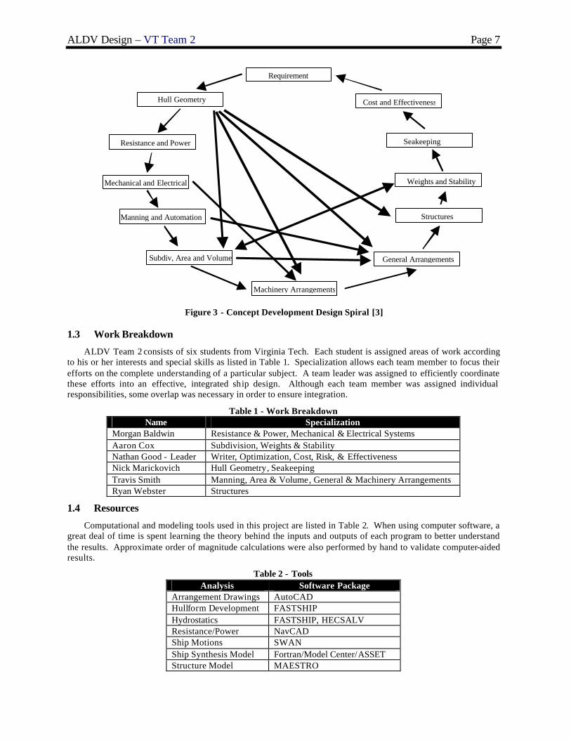
Figure 3 shows the more traditional design spiral process followed in concept development for this project. A complete circuit around the design spiral at this stage is frequently called a feasibility study. It investigates each step in the traditional design spiral at a level of detail necessary to demonstrate that assumptions and results obtained in concept exploration are not only balanced, but feasible. In the process, a second layer of detail is added to the design and risk is included.
ALDV Design – VT Team 2 Page 7
Requirement
Seakeeping
General Arrangements
Weights and Stability
Manning and Automation
Hull Geometry
Resistance and Power
Structures
Mechanical and Electrical
Cost and Effectiveness
Subdiv, Area and Volume
Machinery Arrangements
Figure 3 - Concept Development Design Spiral [3]
1.3 Work Breakdown
ALDV Team 2 consists of six students from Virginia Tech. Each student is assigned areas of work according to his or her interests and special skills as listed in Table 1. Specialization allows each team member to focus their efforts on the complete understanding of a particular subject. A team leader was assigned to efficiently coordinate these efforts into an effective, integrated ship design. Although each team member was assigned individual responsibilities, some overlap was necessary in order to ensure integration.
Table 1 - Work Breakdown Name Specialization
Morgan Baldwin Resistance & Power, Mechanical & Electrical Systems Aaron Cox Subdivision, Weights & Stability Nathan Good - Leader Writer, Optimization, Cost, Risk, & Effectiveness Nick Marickovich Hull Geometry, Seakeeping Travis Smith Manning, Area & Volume, General & Machinery Arrangements Ryan Webster Structures
1.4 Resources
Computational and modeling tools used in this project are listed in Table 2. When using computer software, a great deal of time is spent learning the theory behind the inputs and outputs of each program to better understand the results. Approximate order of magnitude calculations were also performed by hand to validate computer-aided results.
Table 2 - Tools Analysis Software Package
Arrangement Drawings AutoCAD Hullform Development FASTSHIP Hydrostatics FASTSHIP, HECSALV Resistance/Power NavCAD Ship Motions SWAN Ship Synthesis Model Fortran/Model Center/ASSET Structure Model MAESTRO

ALDV Design – VT Team 2 Page 8
2 Mission Definition
The ALDV requirement is based on the ALDV Mission Need Statement (MNS) and Virginia Tech ALDV Acquisition Decision Memorandum (ADM), Appendix A and Appendix B, with elaboration and clarification obtained by discussion and correspondence with the customer, and reference to pertinent documents and web sites referenced in the following sections.
2.1 Concept of Operations
This Concept of Operations (CONOPS) is based on the MNS for a ship-launched, over-the-beach logistics delivery system that solves the problem of establishing a safe and efficient logistics chain from the seabase (Figure 4) or logistics support ship to maneuvering troops ashore. The ALDV will travel from the seabase or blue water environment at high speeds to a location approximately 20 nautical miles off the coastline, where it will launch unmanned cargo-filled gliders to troops ashore (See Figure 5). The ship must operate in “safe” waters, be escorted to complete the mission, or the design must provide for self-defense. ALDV will launch 233 gliders daily fo r a period of three to eight days to meet the landing force daily re -supply requirements for one Marine Expeditionary Brigade (MEB). ALDV will function as a cargo distribution center. ALDV will deliver all of the MEB dry cargo needs and 10 percent of the MEB wet cargo needs to account for troops that are further inland and in hazardous areas where manned V-22 Ospreys are not a safe option.
Figure 4 - ASN Seabase Operational Scenario
Figure 5 - ALDV Idealized Mission Schematic

ALDV Design – VT Team 2 Page 9
The dry cargo includes food, ammunition, medical, and other supplies that a MEB requires per day, and the wet cargo includes 10 percent of the fuel and water that a MEB requires per day. ALDV must also carry the necessary components of the logistics delivery system, which includes unmanned gliders and small rockets to augment the glider range. ALDV will also support V-22 Osprey missions by providing a V-22 haven: at least one helicopter pad and refueling capabilities. The ALDV payload includes V-22 Osprey fuel to support long-range V-22 Osprey missions. A summary of the ALDV payload is listed in Table 3.
Table 3 - ALDV Payload Breakdown [4] Type of Cargo Amount of Cargo (short tons) Total Percentage of Cargo
Dry Cargo 75 24% Wet Cargo 41.5 13%
Rocket Weight 3.5 1% Glider Weight 58 19%
V-22 Fuel 136 43%
A typical twenty-four hour day includes time to launch the gliders, travel time along the coast, and general maintenance time. Launches may occur every two minutes resulting in 7.75 hours of launch time per day. The ship is assumed to travel 250 nautical miles along the coast at 40 knots for 6.25 hours. The remaining 10 hours of the day will be used for maneuvering time, emergency launches, trips to and from the sea base, glider assembly, and general maintenance.
2.2 Projected Operational Environment (POE) and Threat
The ALDV is to function in either a seabase environment or in conjunction with a shuttle ship. A seabase is envisioned as a collection of ships and other platforms at least 100 miles from shore that supports military littoral missions. Objectives of seabasing include: to minimize the operational reliance on shore infrastructure, enhance afloat positioning of joint assets, integrate joint logistics, and improve vertical delivery methods. ALDV is expected to operate the airborne delivery system in littoral regions, which may have a sea state between 0 and 5, and cruise in open water with sea states between 0 and 7. ALDV will either be escorted by a combatant vessel or be outfitted with self defense munitions.
Threats to the US may range from Super Powers to numerous regional powers, and as such the US requires increased flexibility to counter a variety of threat scenarios that may rapidly develop. There are two distinct classes of threats to US national security interests. One is the threat from nations with, or having demonstrated interest in acquiring, superior military capability. Specific weapons systems that could be encountered include ballistic missiles, land and surface launched cruise missiles, significant land-based air assets, and mines. The second is the threat from smaller nations who support, promote, and perpetrate activities which cause regional instabilities detrimental to international security and/or have the potential for development of nuclear weapons. Specific weapons systems include diesel/electric submarines, land-based air assets, and mines.
2.3 Specific Operations and Missions
The mission of ALDV is to provide a platform for the operation of an Advanced Logistics Delivery System (ALDS). ALDS is an original concept developed by the Center for Innovation in Ship Design (CISD) at the Naval Surface Warfare Center – Carderock Division (NSWCCD). ALDS involves launching unmanned gliders filled with cargo from littoral regions over the beach to small, mobile, dispersed troops ashore. ALDV will provide a platform for this airborne logistics delivery system. This involves: § Employing automated techniques for assembling an airborne logistics delivery system. The unmanned gliders
will be assembled at sea to provide on-demand logistics delivery with minimal manning requirements. § Supporting a mechanical launching system for an air delivery system. A mechanical launching system such as
a Linear Induction Motor (LIM) will be required to obtain the required glider launch speeds and accelerations. § Storing the dry and wet cargo necessary to support a MEB ashore. ALDV must store the food, ammunition,
medical, and other dry supplies as well as some of the fuel/water needs of a MEB. A secondary mission of ALDV is to support V-22 logistics operations by providing helicopter landing pads
and refueling capabilities. Another secondary mission is to provide humanitarian aid. As mentioned in Section 2.2, ALDV must carry out these missions from either a seabasing environment or in conjunction with a shuttle ship. Specific mission scenarios are outlined in Section 2.4.
2.4 Mission Scenarios
Mission scenarios for the primary ALDV missions are provided in Table 4 through Table 7.

ALDV Design – VT Team 2 Page 10
Table 4 - Seabase Mission Day Mission scenario
1-14 Cruise from CONUS to seabase 15 Refuel and load cargo
16 Deploy and deliver cargo; refuel V-22s 17-19 Deliver cargo & refuel V-22s 20 Return to seabase, refuel and load cargo 21 Deploy and deliver cargo; refuel V-22s 22-24 Deliver cargo & refuel V-22s
25 Return to seabase, refuel and load cargo
In the Seabase Mission, ALDV travels from CONUS to the seabase, located 250 nautical miles from the shore, to approximately 20 nautical miles from the shore where it operates and delivers its ALDV payload. ALDV continues to travel near the coastline while delivering cargo for a period of four days. ALDV will support the V-22 Osprey on its missions from the seabase to the shore by providing at least one helicopter pad and refueling capabilities.
Table 5 - Seabase Extended Mission Day Mission scenario
1-14 Cruise from CONUS to seabase
15 Refuel and load cargo 16 Deploy and deliver cargo; refuel V-22s 17-21 Deliver cargo & refuel V-22s 22 Return to seabase, refuel and load cargo 23 Deploy and deliver cargo; refuel V-22s
24-28 Deliver cargo & refuel V-22s 29 Return to seabase, refuel and load cargo
In the Seabase Extended Mission, ALDV extends its cargo delivery phase by two days, from four to six, compared to the Seabase Mission. All other phases of the mission are identical.
Table 6 - Shuttle Ship Mission Day Mission scenario
1-14 Cruise from CONUS to littoral waters, meet with shuttle ship 15 Refuel and load cargo from shuttle ship 16-19 Deliver cargo & refuel V-22s 20 Refuel and load cargo from shuttle ship
21-25 Deliver cargo & refuel V-22s In the Shuttle Ship Mission, ALDV travels from CONUS to littoral waters where it meets up with a shuttle ship for refueling and cargo loading. ALDV then travels along the coastline delivering cargo for a period of four days. After four days the ALDV meets back up with the shuttle ship and refuels and reloads cargo.
Table 7 - Shuttle Ship Extended Mission Day Mission scenario
1-14 Cruise from CONUS to littoral waters, meet with shuttle ship 15 Refuel and load cargo from shuttle ship 16-21 Deliver cargo & refuel V-22s
22 Refuel and load cargo from shuttle ship 23-28 Deliver cargo & refuel V-22s

ALDV Design – VT Team 2 Page 11
In the Shuttle Ship Extended Mission, ALDV extends its cargo delivery phase by two days, from four to six, compared to the Shuttle Ship Mission. All other phases of the mission are identical.
2.5 Required Operational Capabilities
In order to support the missions and mission scenarios described in Section 2.4, the capabilities listed in Table 8 are required. Each of these can be related to functional capabilities required in the ship design, and if within the scope of the concept exploration design space, the ship’s ability to perform these functional capabilit ies is measured by explicit Measures of Performance (MOPs).
Table 8 - List of Critical Required Operational Capabilities (ROCs) ROCs Description
AAW 1 Provide anti-air defense in cooperation with other forces AAW 1.2 Provide unit self defense AAW 6 Detect, identify, and track air target AMW 6.1 Conduct day helicopter, short/vertical take-off and landing, and airborne autonomous vehicle (AAV)
operations AMW 6.2 Conduct night helicopter, short/vertical take-off and landing, and airborne autonomous vehicle (AAV)
operations
AMW 6.3 Conduct all-weather helo ops AMW 6.6 Conduct helo refueling ASU 4.1 Detect and track a surface target with radar ASU 4.2 Detect and track a surface target with sonar ASU 6 Disengage, evade and avoid surface attack ASW 8 Detect and track a submarine with sonar ASW 10 Disengage, evade, and avoid submarine attack by employing countermeasures and evasion techniques CCC 1.6 Provide a Helicopter Direction Center (HDC) CCC 3 Provide own unit CCC CCC 4 M aintain NTDS or data link capability LOG 1 Conduct underway replenishment LOG 2 Transfer/receive cargo and personnel LOG 4 Support other ships and aircraft with supplies, fuel, ordnance, and other services MIW 1 Conduct mine-hunting MIW 4 Conduct mine avoidance MIW 6.7 Maintain magnetic signature limits MOB 1 Steam to design capacity in most fuel efficient manner MOB 3 Prevent and control damage MOB 3.2 Counter and control NBC contaminants and agents MOB 5 Maneuver in formation MOB 7 Perform seamanship, airmanship, and navigation tasks (navigate, anchor, mooring, scuttle, life boat/raft
capacity, tow/be towed) MOB 10 Replenish at sea MOB 12 Maintain health and well-being of crew MOB 16.1 Operate in day environments MOB 16.2 Operate in night environments MOB 17 Operate in heavy weather MOB 18 Operate in full compliance of existing US and International pollution control laws and regulations NCO 3 Provide upkeep and maintenance of own unit

ALDV Design – VT Team 2 Page 12
3 Concept Exploration
Chapter 3 describes ALDV Concept Exploration. Trade-off studies, design space exploration, and optimization are accomplished using a Multi-Objective Genetic Optimization (MOGO).
3.1 Standards and Specifications
The ABS Guide for Building and Classing High Speed Naval Craft and General Specifications for Ships of the USN will be used as the primary concept design standards. In addition to these requirements, the following standards shall be used as design “guidance”:
§ Stability and Buoyancy: DDS 079-1 (2002) § Endurance Fuel: DDS 200-1 § Electric Load Analysis: DDS 310-1
3.2 Trade-Off Studies, Technologies, Concepts and Design Variables
Available technologies and concepts necessary to provide required functional capabilities are identified and defined in terms of performance, cost, risk, and ship impact (weight, area, volume, power). Trade-off studies are performed using technology and concept design parameters to select trade-off options in a multi-objective genetic optimization (MOGO) for the total ship design. Technology and concept trade spaces and parameters are described in the following sections.
3.2.1 Hullform Alternatives
The ALDV hullform must satisfy the following general requirements:
§ Minimum endurance range of 2500 nm at 20 knots § Minimum sustained sprint speed of 40 knots § Sprint range of 250 nm § Hull life of 30 years § Safely launch and recover gliders in sea state 5 § Long center hull to allow for the launch of gliders § Large deck area for V-22 Osprey refueling § Low cost
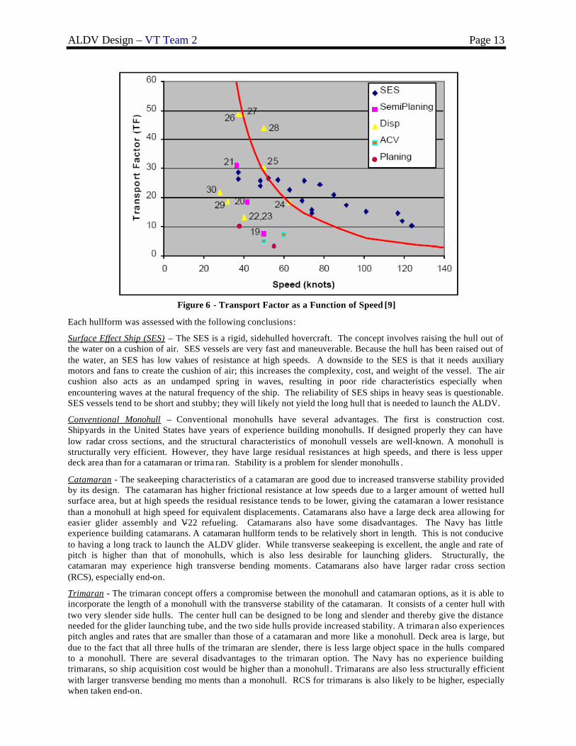
The Transport Factor (TF) concept was used to select vessel types that could carry the loads required at a high speed. TF is a non-dimensionalized relationship between weight, speed, endurance, and propulsion power, and is calculated using one of the following equations [9]:
Figure 6 is a graph of TF with respect to speed for various hullforms. The red line is a theoretical limit of TF
for a displacement hull at a given speed. Based on the graph, four hullforms were selected for review that would yield a modest to moderately high TF (10 – 30) at high speeds (40 – 50 knots). Those four hullforms were:
§ Surface Effect Ship § Slender Monohull § Catamaran § Trimaran
ALDV Design – VT Team 2 Page 13
Figure 6 - Transport Factor as a Function of Speed [9]
Each hullform was assessed with the following conclusions:
Surface Effect Ship (SES) – The SES is a rigid, sidehulled hovercraft. The concept involves raising the hull out of the water on a cushion of air. SES vessels are very fast and maneuverable. Because the hull has been raised out of the water, an SES has low values of resistance at high speeds. A downside to the SES is that it needs auxiliary motors and fans to create the cushion of air; this increases the complexity, cost, and weight of the vessel. The air cushion also acts as an undamped spring in waves, resulting in poor ride characteristics especially when encountering waves at the natural frequency of the ship. The reliability of SES ships in heavy seas is questionable. SES vessels tend to be short and stubby; they will likely not yield the long hull that is needed to launch the ALDV.
Conventional Monohull – Conventional monohulls have several advantages. The first is construction cost. Shipyards in the United States have years of experience building monohulls. If designed properly they can have low radar cross sections, and the structural characteristics of monohull vessels are well-known. A monohull is structurally very efficient. However, they have large residual resistances at high speeds, and there is less upper deck area than for a catamaran or trima ran. Stability is a problem for slender monohulls .
Catamaran - The seakeeping characteristics of a catamaran are good due to increased transverse stability provided by its design. The catamaran has higher frictional resistance at low speeds due to a larger amount of wetted hull surface area, but at high speeds the residual resistance tends to be lower, giving the catamaran a lower resistance than a monohull at high speed for equivalent displacements. Catamarans also have a large deck area allowing for easier glider assembly and V-22 refueling. Catamarans also have some disadvantages. The Navy has little experience building catamarans. A catamaran hullform tends to be relatively short in length. This is not conducive to having a long track to launch the ALDV glider. While transverse seakeeping is excellent, the angle and rate of pitch is higher than that of monohulls, which is also less desirable for launching gliders. Structurally, the catamaran may experience high transverse bending moments. Catamarans also have larger radar cross section (RCS), especially end-on.
Trimaran - The trimaran concept offers a compromise between the monohull and catamaran options, as it is able to incorporate the length of a monohull with the transverse stability of the catamaran. It consists of a center hull with two very slender side hulls. The center hull can be designed to be long and slender and thereby give the distance needed for the glider launching tube, and the two side hulls provide increased stability. A trimaran also experiences pitch angles and rates that are smaller than those of a catamaran and more like a monohull. Deck area is large, but due to the fact that all three hulls of the trimaran are slender, there is less large object space in the hulls compared to a monohull. There are several disadvantages to the trimaran option. The Navy has no experience building trimarans, so ship acquisition cost would be higher than a monohull. Trimarans are also less structurally efficient with larger transverse bending mo ments than a monohull. RCS for trimarans is also likely to be higher, especially when taken end-on.

ALDV Design – VT Team 2 Page 14
Table 9 summarizes the preliminary assessment of hullforms for ALDV. Each design is ranked according to individual criteria, and the sum of the rankings is used to determine which hullforms are best suited for the mission.
Table 9 - Hullform Preliminary Assessment Summary
Preliminary assessment shows that the conventional monohull and the trimaran receive the best overall rankings. It is noted that one of the factors that makes the conventional monohull competitive is that it is the lowest cost alternative. Although it may have the lowest cost, a conventional monohull of the dimensions needed would not provide necessary stability and seakeeping characteristics. A Trimaran, though more costly to build, provides a long center hull to launch the gliders, with good resistance, seakeeping and stability characteristics. Only the Trimaran hull is considered further.
The trimaran parent hullform used for ALDV is based on R/V Triton, a research vessel built by the Royal Navy to test the trimaran concept for future warship designs. Approximately 164 ft of parallel midbody was added to the R/V Triton form to make the hull long enough to launch the ALDV gliders, and the transom was modified to support water jets (Figure 7, Figure 8 and Figure 9).
Figure 7 - Three Dimensional Representation of ALDV Parent Trimaran Hull
Figure 8 - Profile view of trimaran parent hull
Figure 9 - Plan view of trimaran parent hull
Hydrostatic characteristics for the parent hull with a draft of 8.5 meters are listed in Table 10.

ALDV Design – VT Team 2 Page 15
Table 10 - Hydrostatic Characteristics of Parent Trimaran Hull Overall Dimensions (ft) Integrated Properties Waterplane Properties Form Coefficients
LOA 496.74 Volume 671838.58 ft3 LCF 249.57 ft Cb 0.692 LWL 475.42 LCB 256.35 ft Waterplane Area 26655.17 ft2 Cp aft 0.259 Beam Overall 81.42 Wetted Surface Area 45173.27 ft2 Cp fwd 0.3722 Beam WL 73.23 Cp 0.322 Depth 60.70 Cwp 0.766 Freeboard 32.81 Draft 27.89
3.2.2 Sustainability Alternatives
Sustainability characteristics for ALDV include sprint range, endurance range, and provisions storage duration. ALDV sprint range goal and threshold values are 500 nm and 250 n m, respectively. ALDV endurance range goal and threshold values are 3500 nm and 2500 nm, respectively. Provisions and stores duration goal and threshold values for ALDV are 45 days and 20 days.
3.2.3 Propulsion and Electrical Machinery Alternatives
3.2.3.1 Machinery Requirements
Based on the ADM and Program Manager guidance, pertinent propulsion plant design requirements are summarized as follows: General Requirements – The propulsion engines must be non-nuclear, grade A shock certified, and Navy qualified. The machinery system alternatives must span a total power range of approximately 50000–120000 SHP with total ship service power greater than 10000 kW MFLM, unless a pulse power configuration is used. The propulsion engines should have a low IR signature, and cruise/boost options should be considered for high endurance.
Sustained Speed and Propulsion Power – The ship shall be capable of a minimum sustained speed of 40 knots in the full load condition, calm water, and clean hull using no more than 80% of the installed engine rating (maximum continuous rating, MCR) of the main propulsion engine(s) or motor(s), as applicable for mechanical drive plants or electric propulsion plants. The sustained speed goal is 50 knots.
Range and Endurance – The ship shall have sufficient burnable fuel in the full load condition for a minimum range of 2500 nautical miles at 20 knots. The total fuel rate for the propulsion engines and generator sets to be used in determining the endurance fuel requirements shall be calculated using methods described in DDS 200-1. Low speed, fuel efficient propulsion options such as an Integrated Power System (IPS) shall be considered.
Ship Control and Machinery Plant Automation – An integrated bridge system shall be provided in the Navigating Bridge to incorporate integrated navigation, radio communications, interior communications, and ship maneuvering equipment and systems and shall comply with ABS Guide for One Man Bridge Operated (OMBO) Ships. Propulsion control shall be possible from the ship control console (SCC) on the Navigating Bridge and the main control console (MCC) at the Enclosed Operating Station (EOS). In addition to compliance with ABS ACCU requirements for periodically unattended machinery spaces, the machinery centralized control system shall be designed to continuously mo nitor auxiliary systems, electric plant and damage control systems from the SCC, MCC and Chief Engineer’s office, and control the systems from the MCC and local controllers.
Propulsion Engine and Ship Service Generator Certification – Because of the criticality of propulsion and ship service power to many aspects of the ship’s mission and survivability, this equipment shall be non-nuclear, Navy-qualified, and Grade-A shock certified. The propulsion engines should also have a low IR signature. Temperature and Humidity – Design environmental conditions shall be based on the requirement for extended vessel operations in the Persian Gulf. Propulsion engine ratings shall be based on the ship operating temperatures listed in Table 11.
Table 11 - Ship Operating Temperatures Condition Summer Winter
Outside Dry Bulb 40 degrees C -18 degrees C Outside Wet Bulb 30 degrees C
Seawater 35 degrees C -2 degrees C
Fuel - The machinery plant shall be designed for continuous operation using distillate fuel in accordance with ASTM D975, Grade 2-D; ISO 8217, F-DMA, DFM (NATO Code F-76 and JP-5 (NATO Code F-44).

ALDV Design – VT Team 2 Page 16
3.2.3.2 Machinery Plant Alternatives
Nine machinery plant alternatives were considered for ALDV; they are listed in Figure 10. The mission of ALDV requires that the vessel be able to operate at high speeds, so a high power density configuration is necessary. To that end only alternatives with gas turbine engines are considered. Alternatives 1, 2 and 3 are mechanical drive systems with epicyclic (planetary) reduction gears. Alternatives 4, 5 and 6 are mechanical drive systems with a secondary integrated power system (IPS). Alternatives 7, 8 and 9 are full IPS alternatives. All alternatives include a number of ship service gas turbine generators (SSGTGs), depending on ship service needs and other requirements.
Figure 10 - ALDV Propulsion Trade -Off Alternatives
Mechanical Drive – Mechanical drive has several advantages. Gas turbine mechanical drive propulsion has been used in Navy ships since the early 1970s, and the sub-systems are well proven. They weigh less than full and secondary IPS configurations. However, the speed at which the waterjet or propeller operates is directly coupled to engine speed, and minimum engine (idle) speed determines minimum propeller speed. Engines must often be operated at a speed that is not fuel efficient, and below idle speed waterjet buckets must be used to dump thrust. This is especially a problem with gas turbine engines, which are inefficient at part loads and have a high idle speed. Mechanical drive systems are also inherently noisier than electric drive.
Full IPS – A full IPS provides some efficiency and configuration advantages , and has other attractive features. Because the propulsors are driven by motors, engine speed is independent of propulsor speed. The engines can therefore be run at optimum speed for any power output, increasing overall efficiency. IPS has higher transmission losses then a mechanical drive system, but allowing the engines to run at optimum speed compensates for these loses. IPS is also quieter than mechanical drive (mechanically uncouples propulsor from engine), and can use fixed pitch propellers and podded propulsion, both of which can reduce cavitation and overall acoustic signature. Prime movers can be placed anywhere in the ship using IPS, and no shafts are needed to connect the engines to the propulsors; for these two reasons survivability can be increased using IPS. IPS also reduces the need for separate SSGTGs, further increasing the ship’s fuel efficiency. Application of pulse power switching with full IPS enables direct support of the linear induction motor (LIM) without an energy storage device. IPS does have disadvantages. IPS is heavier than a mechanical drive system, and to date no US Navy ships use IPS, increasing risk.
Secondary IPS - A third option for propulsion is to use a secondary IPS with mechanical drive in an IPS cruise /mechanical drive boost configuration. Propulsors are driven either mechanically or by motors. At low speed the

ALDV Design – VT Team 2 Page 17
propulsors are disconnected from the mechanical drive engines and run on motors and SSGTGs . At high speed (above propulsion engine idle speed), the propulsors are reconnected mechanically to the prime movers. Although not as flexible as full IPS, secondary IPS provides better efficiency at low speed, lower acoustic signature at low speed, and is lighter than a full IPS configuration.
Waterjet Propulsors – ALDV sprint speed is required to be greater than 40 knots. At this speed, maximum propulsion efficiency is achieved with waterjet propulsion, as shown in Figure 11. In ALDV, waterjets similar to Kamewa 225SII are considered. These waterjets are capable of producing 16 to 30 MW of power. ALDV can accommodate up to three waterjets in its center hull. The Kamewa waterjet system is shown in Figure 12 with performance curves in Figure 13 and Figure 14.
Figure 11 - Overall Propulsive Coefficient for Different Propulsion Alternatives at Various Speeds [3]
Figure 12 - Kamewa Waterjet Propulsion System [3]

ALDV Design – VT Team 2 Page 18
Figure 13 - Kamewa 225SII Waterjet Power and Thrust Curves [3]
Figure 14 - Kamewa 225SII Waterjet Speed/Power Curves [3]
Propulsion Engine Alternatives – Two gas turbine engines are considered as engine alternatives, the LM 2500+ and the MT-30 Marine Gas Turbine. The WR-21 ICR was also considered early in concept exploration. It was decided that the added weight of the ICR system was not feasible for the high-speed, high power density requirements of ALDV. The LM 2500+ is used in many Navy ships today. It is US Navy qualified, Grade A Shock certified, and it is lightweight. One LM 2500+ can produce 26099 bkW of power. The MT-30 is heavier than the LM 2500+, but it delivers more power at 36000 bkW. It has a slightly lower exhaust temperature and a slightly lower SFC then the LM 2500+. The LM 2500+ was considered in lower power propulsion configurations, and the MT-30 was considered for higher power configurations. Characteristics of both engines are provided in Table 12 and Table 13.

ALDV Design – VT Team 2 Page 19
Table 12 - LM 2500+ Characteristics
Table 13 - MT-30 Marine Gas Turbine Characteristics
Ship Service Generator Option – Because of weight considerations only gas turbine generators were considered. The SSGTG that was selected is the DDA 501-K34. It has a high power density and is US Navy qualified and Grade A shock certified. Characteristics of the DDA 501-K34 are listed in Table 14.
Table 14 - DDA 501-K34 Ship Service Generator Characteristics
All of the above alternatives were considered for selection in the ship synthesis model based on the characteristics of each alternative listed in Table 15 and Table 16. The data in the table was collected by creating alternative propulsion plants in a monohull baseline ship using ASSET , supplemented with manufacturer data.

ALDV Design – VT Team 2 Page 20
Table 15 - Propulsion System Alternative Data
Table 16 - Propulsion System Alternative Data (cont)

ALDV Design – VT Team 2 Page 21
3.2.4 Automation and Manning Parameters
The ALDV must function as a cargo transport and distribution center providing cargo needs for troops ashore. A high level of automation is necessary to organize and distribute large quantities of cargo in short periods of time. Increased automation and reduced manning may also reduce ALDV life cycle cost and minimize personnel vulnerability. Many automated cargo handling technologies from industry are applicable to ALDV. Some of these processes include conveyor belts, elevators, robotic pickers, and radio frequency identification (RFID). While these technologies exist, their application onboard a ship may present some new challenges. Other general automation technologies that may be considered for ALDV include enabling technologies (ex. fiber optics), watch standing technologies (ex. electronic log keeping), and condition based maintenance technologies (ex. Integrated Condition Assessment System-ICAS).
In concept exploration it is difficult to deal with automation manning reductions explicitly, so a ship manning and automation factor is used. This factor represents reductions from “standard” manning levels resulting from automation. The manning factor, CMAN, varies from 0.5 to 1.0. It is used in the regression based manning equations shown in Figure 15. A manning factor of 1.0 corresponds to a “standard” fully-manned and conventionally-automated ship. A ship manning factor of 0.5 results in a 50% reduction in manning and implies a large increase in automation. The manning factor is also applied using simple expressions based on expert opinion for automation cost, automation risk, damage control performance and repair capability performance. Manning calculations are shown in Figure 15. A more detailed manning analysis is performed in concept development.
The parametric manning equations are based on the following independent variables: WP : Total payload weight WVP : Variable payload weight VD : Deck house volume VHT : Total hull volume NSSG : Number of ship service generators NPROP : Number of propellers or propulsors
NO 3 ceil 1 CMAN
WP WVP−( )300
⋅+VD
100000+
+:=
NE ceil CMAN NPROP( ) 2⋅ NSSG+WP WVP−( )
50+
VHT VD+( )30000
+
⋅
:=
where NO is number of ship officers and NE is number of ship enlisted men
NT NO NE+:= NA ceil 0.1 NT⋅( ):=
where NT is the total number of ship crew andNA is the additional accomodations
Figure 15 - ALDV Concept Exploration Manning Calculation
3.2.5 Combat System Alternatives
A range of combat system alternatives was identified, and ship impact was assessed for each configuration. The impact of the ALDS mission systems was also identified. Analytical Hierarchy Process (AHP) and Multi-Attribute Value Theory (MAVT) were used to estimate the Value of Performance (VOP) for each system alternative. The VOPs are included in the total ship synthesis model and used to evaluate effectiveness. The combat system alternatives and ALDS mission systems are selected based on effectiveness, cost, and risk in a multi-objective optimization.
3.2.5.1 MCM
Mine Countermeasures (MCM) includes any activity to prevent or reduce the danger from enemy mines. Passive countermeasures operate by reducing a ship’s acoustic and magnetic signatures, while active countermeasures include mine avoidance, mine-hunting, minesweeping, detection and classification, and mine neutralization. MCM system alternatives are listed in Table 17.
Table 17 - MCM System Alternatives ID MCM System Alternatives 1 2 3 - Degaussing 1 1
37 Mine Avoidance Sonar 1 MCM Value of Performance (VOP1) 1.0 0.5 0.0

ALDV Design – VT Team 2 Page 22
Specific sub-system descriptions are as follows: § Mine Avoidance Sonar (Figure 16) – Mine Avoidance Sonar (MAS) is an active MCM that will allow
ALDV to detect and avoid mines and other dangerous objects. The Multi-Purpose Sonar System VANGUARD is a versatile two frequency active and broadband passive sonar system. Though primarily designed to detect mines it can be used to detect other moving or stationary objects. VANGUARD also assists in navigation. The passive sonar mode can be used to detect other sonar signals and underwater noise over a wide range of frequencies.
Figure 16 - Mine Avoidance Sonar
§ Degaussing (Figure 17) – Degaussing is a passive MCM that reduces the ALDV magnetic signature. It works by passing a current through a mesh of wires to generate a magnetic field that cancels out the ship’s magnetic field.
Figure 17 - Degaussing
3.2.5.2 ASUW
ALDV Anti-Surface Warfare (ASUW) system alternatives are listed in Table 18.
Table 18 - ASUW System Alternatives
ID ASUW System Alternatives 1 2 3 18 Surface Search Radar - AN/SPS-73 1 1 1 19 DDG51 Small Arms and Pyro Stowage 1 1 1 25 1X 7m RHIB 1 1 1 24 IR Search and Track System (IRST) 1 1 20 1X 30mm CIGS Gun Mount 1 of 4 (Close In Gun System) 1 21 1X 30mm CIGS Gun Ammo Stowage 2 of 4 1 22 1X 30mm CIGS Gun Ballistic Protection 3 of 4 1 23 1X 30mm CIGS Gun Ammo – 2500 Rounds 4 of 4 1 ASUW Value of Performance VOP3 (also add VOP3 value
from LAMPS) 0.5 0.2 0.0
ALDV Design – VT Team 2 Page 23
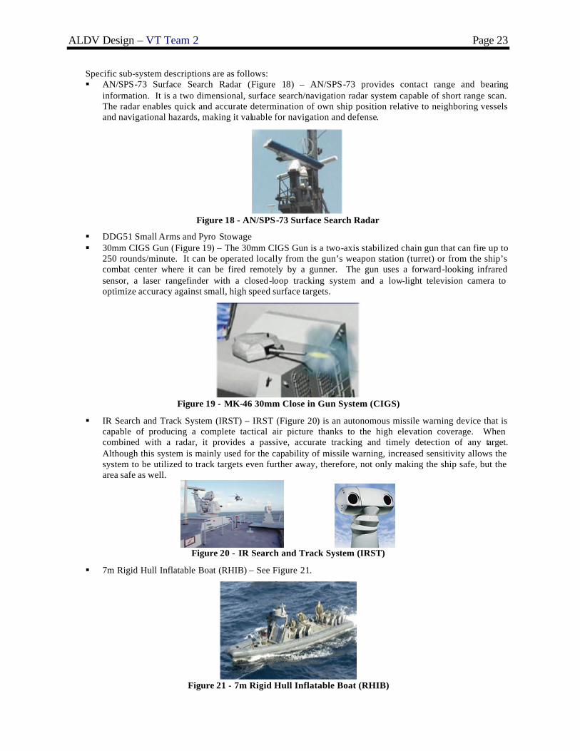
Specific sub-system descriptions are as follows: § AN/SPS-73 Surface Search Radar (Figure 18) – AN/SPS-73 provides contact range and bearing
information. It is a two dimensional, surface search/navigation radar system capable of short range scan. The radar enables quick and accurate determination of own ship position relative to neighboring vessels and navigational hazards, making it valuable for navigation and defense.
Figure 18 - AN/SPS-73 Surface Search Radar
§ DDG51 Small Arms and Pyro Stowage § 30mm CIGS Gun (Figure 19) – The 30mm CIGS Gun is a two-axis stabilized chain gun that can fire up to
250 rounds/minute. It can be operated locally from the gun’s weapon station (turret) or from the ship’s combat center where it can be fired remotely by a gunner. The gun uses a forward-looking infrared sensor, a laser rangefinder with a closed-loop tracking system and a low-light television camera to optimize accuracy against small, high speed surface targets.
Figure 19 - MK-46 30mm Close in Gun System (CIGS)
§ IR Search and Track System (IRST) – IRST (Figure 20) is an autonomous missile warning device that is capable of producing a complete tactical air picture thanks to the high elevation coverage. When combined with a radar, it provides a passive, accurate tracking and timely detection of any target. Although this system is mainly used for the capability of missile warning, increased sensitivity allows the system to be utilized to track targets even further away, therefore, not only making the ship safe, but the area safe as well.
Figure 20 - IR Search and Track System (IRST)
§ 7m Rigid Hull Inflatable Boat (RHIB) – See Figure 21.
Figure 21 - 7m Rigid Hull Inflatable Boat (RHIB)

ALDV Design – VT Team 2 Page 24
3.2.5.3 ASW
The ALDV Anti-Submarine Warfare (ASW) systems include a LAMPS MK3 SH-70 Seahawk Helo (Section 3.2.5.7) and an AN/SLQ-25 NIXIE system as listed in Table 19.
Table 19 - ASW System Alternatives ID ASW System Alternatives 1 2 26 AN/SLQ -25 NIXIE 1 ASW Value of Performance VOP4 (also add VOP4 value
from LAMPS) 0.2 0.0
The NIXIE sub-system is detailed as follows: § NIXIE is a passive, electro-acoustic decoy system. It is used to supply deceptive countermeasures against
acoustic homing torpedoes. The AN/SLQ-25A includes improved deceptive countermeasure capabilities. It employs an underwater acoustic projector housed in a streamlined body which is towed astern on a combination tow/signal-transfer coaxial cable. An onboard generated signal is used by the towed body to produce an acoustic signal to lure the hostile torpedo away from the ship. The AN/SLQ -25B includes improved deceptive countermeasure capabilities, a fiber optic display LAN, a torpedo alert capability and a towed array sensor.
3.2.5.4 AAW
ALDV AAW system alternatives include systems listed in Table 20. The alternatives include: MK XII AIMS IFF, AN/SRS-1A(V) Combat DF, SLQ-32(V)2 Passive ECM, SLQ -32(V)3 ECM, Advanced Integrated Electronic Warfare System (AIEWS), MK 16 CIWS, RAM 8 Cell, MK 137 LCHRs (Combined MK 53 SRBOC & NULKA LCHR). All sensors and weapons in each suite are integrated using the Ship Self Defense System (SSDS). This system is intended for installation on all non-Aegis ships. The SSDS improves effectiveness by coordinating hard kill and soft kill and employing them to their optimum tactical advantage. SSDS does not improve the performance of any sensor or weapon beyond its individual capability. The SSDS is a resourceful system that can be used as a tactical decision aid or an automatic weapon system. SSDS uses mostly Commercial Off-the-Shelf (COTS) products, including fiber optic Local Area Network (LAN). SSDS employs single or multiple Local Access Unit (LAU) cabinets with an Uninterruptible Power Supply (UPS) and VME card cage. Processor cards are identical and interchangeable, so spares can be stocked.
Table 20 - AAW and SEW System Alternatives ID AAW System Alternatives 1 2 3 4 1 MK XII AIMS IFF 1 1 1 1 2 AN/SRS-1A(V) Combat DF 1 1 1 1 3 Ship Self Defense System (SSDS) 1 1 1 4 SLQ-32[V]2 Passive ECM [SEW] 1 1 5 SLQ-32[V]3 ECM [SEW] 1 16 2X-MK 137 LCHRs (Combined MK 53 SRBOC &
NULKA LCHR) (1 of 2) 1 1 1
17 2X-MK 137 LCHRs Loads (4NULKA, 12 SRBOC) (2 of 2)
1 1 1
7 1X MK 16 CIWS Gun Mount (1 of 5) 2 1 8 1X MK 16 CIWS Local Control (2 of 5) 2 1 9 1X MK 16 CIWS Remote Control (3 of 5) 2 1 10 1X MK 16 CIWS Workshop (4 of 5) 2 1 11 1X MK 16 CIWS 25mm Guns – Ammo (5 of 5) 2 1 12 RAM Launcher – 8 Cell – Launcher (1 of 4) 1 13 RAM Launcher – 8 Cell – Control Room (2 of 4) 1 14 RAM Launcher – 8 Ready Service Missiles (3 of 4) 1 15 RAM Launcher – 8 Cell – 8 RAM Missile
Magazine (4 of 4) 1
AAW Value of Performance (VOP5) 1.0 0.8 0.3 0.0

ALDV Design – VT Team 2 Page 25
Specific sub-system descriptions are as follows:
§ AN/UPX-36(V) CIFF-SD (Centralized Id. Friend or Foe) is a centralized, controller processor-based system that associates different sources of target information. It accepts, processes, correlates and combines IFF sensor inputs into one IFF track picture. It controls the interrogations of each IFF system and ultimately identifies all targets as a friend or foe.
§ AN/SRS-1A(V) Combat DF (Direction Finding) is an automated long range hostile target signal acquisition and direction finding system. It can detect, locate, categorize and archive data into the ship’s tactical data system and provides greater flexibility against a wider range of threat signals. It Provides warship commanders near-real-time indications and warning, situational awareness, and cueing information for targeting systems.
§ Ship Self Defense System (SSDS) is an integrating element of Quick Reaction Combat Capability (QRCC). SSDS is planned for all Non-Aegis ships. It does not improve the performance of any sensor or weapon beyond its stand-alone capability. SSDS does coordinate hard kill and soft kill and employ them to their optimum tactical advantage. It can be used with options ranging from a tactical decision aid to an automatic weapon system.
Phalanx Close-In Weapons System (CIWS, Figure 22) provides defense against low altitude ASCMs. It is a hydraulically driven 20 mm gatling gun capable of firing 4500 rounds per minute. CIWS magazine capacity is 1550 rounds of ammunition. It is computer controlled to automatically correct aim errors. Phalanx Surface Mode (PSUM) incorporates its side mounted Forward Looking Infrared Radar (FLIR) to engage low, slow or hovering aircraft and surface craft
Figure 22 - MK 16 Close in Weapons System (CIWS)
Rolling Airframe Missile (RAM, Figure 23) is the goal missile system. It is cued from SSDS. RAM is a self contained package. It can use Active Optical Target Detector (AOTD) for improved effectiveness in presence of aerosols. RAM also features Infrared Modular Update (IRMU) to provide capability against non-RF radiating threats. It is comprised of the GMLS (launching system) and GMRP (round pack). RAM is effective and lethal against most current ASCMs. Its capability against LAMPS, aircraft, and surface targets is being developed.
Figure 23 - Rolling Airframe Missile (RAM)

ALDV Design – VT Team 2 Page 26
§ The Decoy Launching System (DLS) is a combined MK 53 SRBOC and NULKA LCHR (Figure 24). NULKA is a rapid response Active Expendable Decoy (AED) System. It is a highly effective defense for ships of cruiser size or below against modern radar homing anti-ship missiles. Super Rapid Bloom Offboard Countermeasures (SRBOC) Chaff and DLS launches decoys at a variety of altitudes to confuse missiles by creating false signals.
Figure 24 - MK 53 SRBOC and NULKA
3.2.5.5 SEW
Electronic Warfare system alternatives include AN/SLQ -32(V)2 Passive ECM, AN/SLQ-32(V)3 ECM and Advanced Integrated Electronic Warfare System (AIEWS). Descriptions of the specific sub-systems are as follows: § AN/SLQ -32(V)2 Passive ECM and AN/SLQ-32(V)3 ECM Electronic Warfare (EW) Systems provide
warning, identification, and direction-finding of incoming anti-ship cruise missiles (ASCM). They provide early warning, identification, and direction-finding against targeting radars. They also provide jamming capability against targeting radars.
§ Advanced Integrated Electronic Warfare System (AIEWS) is an advanced SEW system. It is the Navy’s next -generation shipboard EW system designed to meet the projected threat in the 2005 to 2010 time frame. The primary functions are detection, correlation, and identification of threat emitters as well as automatic employment of coordinated on-board countermeasures.
3.2.5.6 C4ISR
Command, Control, Communications, Computers, Intelligence and Surveillance (C4ISR) system alternatives include those listed in Table 21.
Table 21 - C4ISR System Alternatives ID C4ISR System Alternatives 1 2 34 DDG51 Navigation System 1 1 35 COMMS Suite Level A 1 36 COMMS Suite Level B 1 C4I Value of Performance (VOP2) 1.0 0.0
Specific sub-system descriptions are as follows: § DDG51 Navigation System – The navigational system for the ALDV will be based on the latest version of
the DDG51 Navigation System, which was designed for use in Arleigh-Burke class destroyers. Because the ALDV is primarily a logistics delivery ship and will not be involved in naval strike operations, the navigation system may not have some of the offensive weapon system interfaces that the actual DDG51 system may have.
§ COMMS Suite Level A or B – A communications suite will be installed to enable communications with all elements in the battle space, as well as within the ship itself.

ALDV Design – VT Team 2 Page 27
Figure 25 - SH-60 Seahawk Helicopter (LAMPS)
3.2.5.7 LAMPS (Light Airborne Multi-Purpose System)
The LAMPS MKIII (SH-60) Seahawk Helicopter (Figure 25) can perform many roles. It can perform ASW, ASUW, search and rescue, SPECOPS, and cargo lift. It is able to deploy sonobuoys and torpedoes in the ASW role. LAMPS also has a retractable in-flight fueling probe for prolonged loitering time, and its radars can extend a ship’s radar capabilities. It provides self-defense with two 7.62mm machine guns, and is also capable of carrying and launching AGM -114 Hellfire missiles, AGM -119 Penguin missiles, and Mk46 torpedoes. The LAMPS system alternatives are listed in Table 22.
Table 22 - LAMPS System Alternatives ID LAMPS System Alternatives 1 2 3 4 27 ASW Control System 1 1 28 LAMPS MKIII SH-60B HELO and Hangar (Based) 1 29 LAMPS MKIII Aviation Shop and Office 1 30 LAMPS MKIII:HELO Securing System 1 1 1 31 LAMPS Aviation Magazine - Sonobuoys, (12) MK46 - (24)
HELLFIRE - (6) PENQUIN 1 1 1
32 LAMPS MKIII Aviation Fuel System 1 1 1 1 33 SINGLE SH-60 – Mission Fuel 1 1 1 1 ASUW Value of Performance (VOP3) 0.5 0.2 0.2 0.0 ASW Value of Performance (VOP4) 0.8 0.5 0.2 0.0
3.2.5.8 Combat Systems Payload Summary
In order to trade-off combat system alternatives with other alternatives in the total ship design, combat system characteristics listed in Table 23 are included in the ship synthesis model data base.
3.3 ALDS Mission System
The following section describes components necessary to meet the requirements of the ALDS mission specified in the MNS. The only design variable for the ALDS Mission System is the number of days ALDV is required to deliver MEB cargo without replenishment. Therefore, each of the following components is included in all designs, and the payload characteristics for each component vary with the number of mission days.
3.3.1 Dry Cargo Stores
ALDS cargo requirements include 75 short tons of dry cargo per MEB day. Dry cargo includes food, ammunition, medical, and other supplies required by a MEB, and it is assumed that dry cargo is packaged in standard 4’x 4’ x 4’ pallets (Figure 26) stacked two high in the ship. Dry cargo is broken down into two general categories, ammunition cargo and other dry cargo, for payload characteristics calculations (Table 24) since ammunition cargo must be stored in a magazine.

ALDV Design – VT Team 2 Page 28
Table 23 - Combat System Ship Synthesis Characteristics
Table 24 - Dry Cargo Payload Characteristics [4] Cargo Type Weight (ltons/day) Arrangeable Area (ft2/day)
Ammunition 29.90 650 Other Dry Cargo 37.07 800
Figure 26 - Standard 4’x4’x4’ Pallets
3.3.2 Wet Cargo Stores
A secondary mission of ALDS is to provide 10 percent of the wet cargo needs for a MEB which supports troops that are further inland and in hazardous areas where manned V-22 Ospreys (Figure 27) are not a safe option. ALDS wet cargo stores account for the space required to store this fuel and water, and the space required to store

ALDV Design – VT Team 2 Page 29
JP-5 fuel used for V-22 refueling. All wet cargo is assumed to be bulk cargo in the payload characteristics table (Table 25).
Figure 27 - V-22 Osprey
Table 25 - Wet Cargo Stores Payload Characteristics [4] Cargo Type Weight (ltons/day) Volume (ft3/day)
ALDS Fuel Cargo 20.09 986.22 ALDS Fresh Water Cargo 16.96 608.52 V-22 JP-5 Fuel 121.70 5198.36
3.3.3 Cargo Handling
ALDS Cargo Handling requires a pallet stowage room accessed with automated pickers (Figure 28). It is assumed that containers are opened and broken down into pallets at the sea base or on the shuttle ship. Forklifts transport the pallets over a retractable ramp directly to the pallet stowage room. The pallets are placed in specified locations in aisles running longitudinally in the ship. Once the pallets are loaded from the sea base platform and the ship is underway, an automated picker (Figure 29) selects the requested cargo and places it into the ALDS center-bodies.
Automated Picker
Cargo (pallet) Bays Conveyor
Figure 28 - ALDS Cargo Handling Room
Figure 29 - Automated Picker [11]

ALDV Design – VT Team 2 Page 30
Table 26 lists the payload characteristics for the ALDS cargo handling system. The area accounts for space for two cargo elevators.
Table 26 - ALDS Cargo Handling Payload Characteristics Component # of Components Weight (ltons) Power Required (kW) Area Required (ft2)
Automated Pickers 4 1.79 2.54 N/A Rails for Pickers 3 2.68 0 N/A Misc. Forklifts 3 0.89 0 N/A
TOTAL 5.36 2.54 600
3.3.4 Glider Components
Each ALDS unmanned glider consists of several components: center-body bottom, center-body top, ribs, spars, cargo plate, gas tanks, control surfaces, and wing pods. Some of these components are illustrated in Figure 30.
Figure 30 - ALDS Unmanned Glider Components
The center-body of the ALDS glider is a large and hollow structure, and the ALDS mission requires the launch of 233 of these gliders each day for a number of days. The large volume requirement resulting from storing assembled ALDS gliders onboard the ship makes the off-board fabrication and assembly very unattractive. To address this problem, methods of manufacturing and assembling the ALDS glider onboard the ship were investigated. The two main manufacturing options researched were Plastic Injection Molding (PIM) and High Velocity Electro-Magnetic Stamping (HVEMS). PIM involves heating thermoplastics in a heat chamber and then forcing that material into a mold through the use of a pressure gradient [10], while HVEMS involves high speed stamping to allow aluminum to be stretched to higher levels of strain [6]. Although PIM and HVEMS manufacturing methods significantly reduce the ALDS glider space requirement, they are both complex and costly systems that have not been developed for something as large as an ALDS center-body.
Since the technology has not been developed for a complete manufacturing and assembly process, an assembly-only process was also investigated, referred to as “Stacking” in this report. Stacking involves separating each ALDS center-body into a top and bottom half and then stacking these separate halves within each other in a manner similar to packaged plastic cups. A volume analysis was conducted comparing the volume of these stacks to the volume of pre-assembled ALDS center-bodies for a period of four mission days (Figure 31). Also included in the volume analysis were theoretical estimates for PIM and HVEMS based on the volume of the raw materials and the size of the machinery needed to manufacture ALDS center-bodies. The figure shows that as sembling center-bodies off board and storing them on the ship requires a much larger volume than assembling center-bodies onboard the ship. The volume requirements of these three onboard options are similar, making Stacking a near-term solution due to its current availability and simplicity. Assuming the “Stacking” concept, areas of the individual ALDS glider components were summed, and these payload characteristics are listed in Table 29. This table also lists the payload characteristics of the ALDS rockets used to augment the glider range. The weights of individual components were not calculated as the weight of an empty assembled ALDS glider was taken to be 500 pounds. A conceptual assembly room onboard the ship was developed using these areas and the “Stacking” method. This assembly room is discussed in the next section of the report.
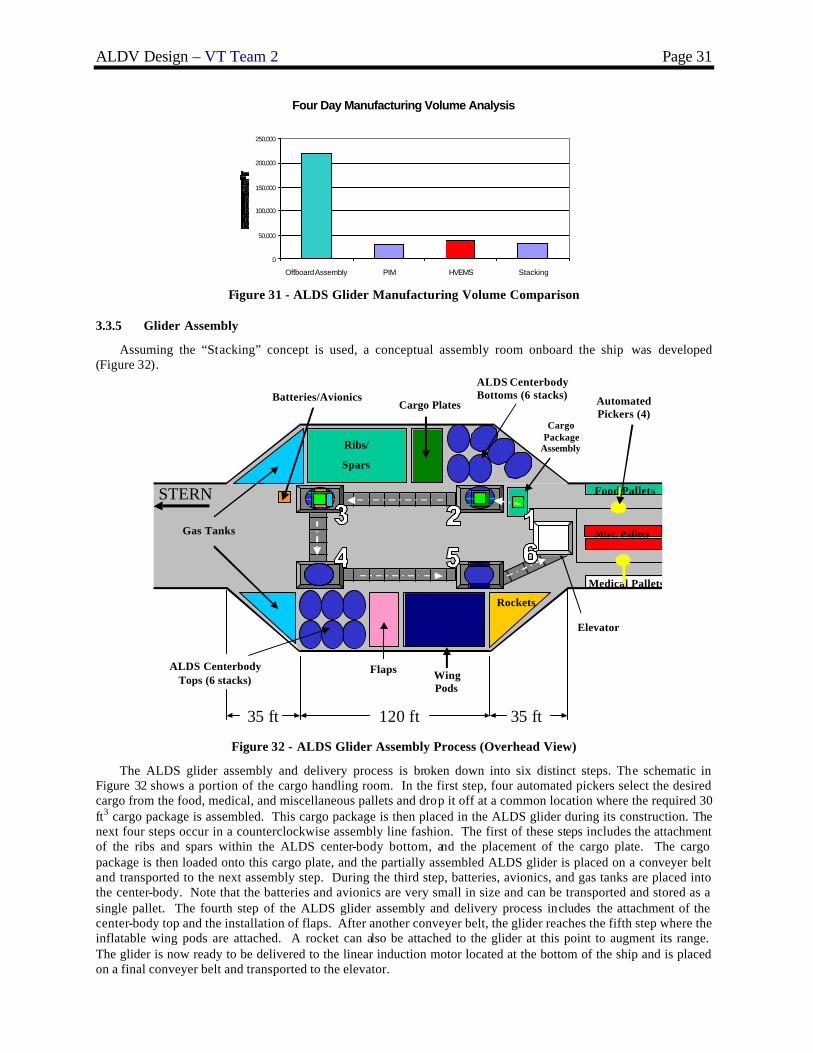
ALDV Design – VT Team 2 Page 31
Four Day Manufacturing Volume Analysis
0
50,000
100,000
150,000
200,000
250,000
Offboard Assembly PIM HVEMS Stacking
Figure 31 - ALDS Glider Manufacturing Volume Comparison
3.3.5 Glider Assembly
Assuming the “Stacking” concept is used, a conceptual assembly room onboard the ship was developed (Figure 32).
Food Pallets
Misc. Pallets
Medical Pallets
Cargo Package
Assembly
Gas Tanks
Batteries/Avionics
Elevator
Cargo Plates
Ribs/
Spars
ALDS CenterbodyBottoms (6 stacks)
Wing Pods
ALDS Centerbody Tops (6 stacks)
Rockets
Flaps
Automated Pickers (4)
120 ft35 ft 35 ft
STERN
Figure 32 - ALDS Glider Assembly Process (Overhead View)
The ALDS glider assembly and delivery process is broken down into six distinct steps. The schematic in Figure 32 shows a portion of the cargo handling room. In the first step, four automated pickers select the desired cargo from the food, medical, and miscellaneous pallets and drop it off at a common location where the required 30 ft3 cargo package is assembled. This cargo package is then placed in the ALDS glider during its construction. The next four steps occur in a counterclockwise assembly line fashion. The first of these steps includes the attachment of the ribs and spars within the ALDS center-body bottom, and the placement of the cargo plate. The cargo package is then loaded onto this cargo plate, and the partially assembled ALDS glider is placed on a conveyer belt and transported to the next assembly step. During the third step, batteries, avionics, and gas tanks are placed into the center-body. Note that the batteries and avionics are very small in size and can be transported and stored as a single pallet. The fourth step of the ALDS glider assembly and delivery process includes the attachment of the center-body top and the installation of flaps. After another conveyer belt, the glider reaches the fifth step where the inflatable wing pods are attached. A rocket can also be attached to the glider at this point to augment its range. The glider is now ready to be delivered to the linear induction motor located at the bottom of the ship and is placed on a final conveyer belt and transported to the elevator.

ALDV Design – VT Team 2 Page 32
The payload characteristics for the ALDS glider assembly system are presented in Table 27. They include the weight and power estimates for the conveyers and automated cranes necessary to transfer glider components to the desired destinations. The conveyer area necessary for this system is also included.
Table 27 - ALDS Glider Assembly Payload Characteristics Component Weight (ltons) Power Required (kW) Area Required (ft2)
Automated Cranes 8.93 0.19 0 Conveyer Belts 3.57 14.92 7250
TOTAL 12.50 15.11 7250
3.3.6 Linear Induction Motor
A linear induction motor (LIM) is simply a rotary motor sliced and rolled flat (Figure 33). The primary of a LIM is analogous to a stator and usually makes up the windings of the track. Similarly, the secondary of a LIM is analogous to the rotor. During operation, an alternating electric current is supplied to the coils of the primary to change the polarity of the magnetized coils. This change of polarity results in a magnetic field in front of the vehicle that pulls it forward and a magnetic field behind the vehicle that pushes it forward. Examples of this concept can be seen in modern day roller coaster design.
Figure 33 - Conceptual LIM Illustration
To meet the requirements of the ALDS mission specified in the MNS, the ALDV LIM must launch 1500 pound gliders at a speed of 500 knots with an acceleration of 30 g’s. A 365 ft long track is required to achieve this acceleration. This length was used in the calculation of the LIM hull area lis ted in Table 28. The weight and power estimates were based on calculations performed at NSWCCD and EMALS (Electro-Magnetic Aircraft Launch System) specifications.
Table 28 - LIM Payload Characteristics Weight (ltons) Power Required (kW) - Cruise Hull Area (ft2)
203.8 700 6270
The LIM track design is constrained by the requirement that each ALDS glider be launched at an angle of 30 degrees. A sudden 30 degree turn at the end of a horizontal track creates large forces on both the track and the ship, and it also results in energy losses and decreased range for the glider. These disadvantages eliminate the possibility of using a completely horizontal track with a sudden turn and encourage a curved track design. The optimal curved design involves the largest radius of curvature that yields a launch angle of 30 degrees. A large radius of curvature is ideal because increasing the radius of curvature decreases the centrifugal force exerted on the track. However, there is a limit on the radius of curvature of the track based on the depth of the ship. As a compromise, a partially horizontal and partially curved track was selected and placed along the keel of the ship.

ALDV Design – VT Team 2 Page 33
This final track design is shown in Figure 34. The track, which is enclosed in a watertight tube, was allowed to extend a few feet above the main deck to increase curvature without decreasing flight deck visibility. There are a number of advantages associated with locating the LIM launch tube along the bottom of the ship. The first of these advantages is the minimization of air draft. Air draft is the distance from a vessel’s water line to the upper most point on the vessel. With this LIM configuration, the air draft is based on the height of the deck house, eliminating most of the problems related to overhead obstructions such as bridges, cranes, loading arms, etc. Another advantage of this design is the strong structural support provided by the keel in order to counteract the large forces generated by accelerating a mass to 30 g’s. Locating the LIM launch tube within the ship also protects the system from weather and keeps the center of gravity of the ship low. One final advantage of this configuration is that locating the LIM launch tube low in the ship allows for the cargo handling room and assembly room to be located high enough in the ship that watertight bulkheads are not necessary. The elimination of watertight bulkheads on the cargo handling and assembly level allows for the easy horizontal transfer of materials.
Figure 34 - LIM Track Design
3.3.7 ALDS Mission System Payload Summary
Table 29 is a summary of the ALDS mission system payload characteristics. New information presented in this table includes weight groupings and vertical center of gravity estimates (HD10).
Table 29 - ALDS Mission System Payload Characteristics Summary

ALDV Design – VT Team 2 Page 34
3.4 Design Space
Sixteen design variables (Table 30) are used to describe the ALDV design. The optimizer chooses the design variable values from the range provided and inputs the values into the ship synthesis model. Once the design variable values are input into the ship synthesis model, the ship is balanced, checked for feasibility, and assessed based on risk, cost, and effectiveness. Hull design parameters (DV1-4) are described in Section 3.2.1. Sustainability alternatives (DV15) and performance measures are described in Section 3.2.2. Propulsion and Machinery alternatives (DV5 and 14) are described in Section 3.2.3. Automation alternatives (DV6) are described in Section 3.2.4. Combat system alternatives (DV 7-13) are described in Section 3.2.5. The final design variable (DV16) is the ALDS Mission Duration.
Table 30 - ALDV Design Variables (DVs) DV Description Metric Range
1 Length (used to geosim parent) m 150-200
2 Deck house Volume m3 500-3000
3 Deck house Material Type alternative 1 – steel, 2 – aluminum
4 Ballast Type alternative 0 – clean ballast, 1- compensated fuel system
5 Propulsion System Type alternative 1-9
6 Manning and Automation Factor ND 0.5 – 1.0
7 AAW Alternative alternative 1 (goal), 2,3,4(threshold)
8 ASUW Alternative alternative 1 (goal), 2,3(threshold)
9 ASW Alternative alternative 1 (goal), 2(threshold)
10 MCM Alternative alternative 1 (goal), 2(threshold)
11 C4I Alternative alternative 1 (goal), 2(threshold)
12 LAMPS alternative 1 (goal), 2,3,4(threshold)
13 Degaussing System alternative 0 – none, 1- degaussing system 14 Collective Protection System alternative 0- none, 1-partial, 2- full 15 Provisions Duration days 20-45
16 ALDS Mission Duration days 3-8
3.5 Ship Synthesis Model
A ship synthesis model is necessary to balance and assess the feasibility of designs selected by the optimizer in Concept Exploration. Modules in the ship synthesis model are modified from previous models in Fortran, and the model is incorporated and executed in the program Model Center (MC). Design variables and other inputs are compiled in the Input Module, which is linked to all of the other modules. There are 13 other modules, nine of which make up the physics-based ship synthesis model. The other four modules include Feasibility, Cost, Risk, and OMOE. The Feasibility Module determines the overall design feasibility of each ALDV design by comparing available design characteristics to required design characteristics. The Cost, Risk, and OMOE Modules are the three objectives of the optimization process. The goal of optimization is to maximize effectiveness while minimizing cost and risk. The Multi-Objective Genetic Optimization (MOGO) is run in MC using the Darwin optimization plug-in. Figure 35 displays the ALDV ship synthesis model in MC. Measures of Performance (MOPs), Values of Performance (VOPs), an Overall Measure of Effectiveness (OMOE), Overall Measure of Risk (OMOR), and Average Follow Ship Acquisition Cost are calculated by the synthesis model.

ALDV Design – VT Team 2 Page 35
Figure 35 - Ship Synthesis Model in Model Center (MC)
The ship synthesis model is organized into modules as shown in Figure 35: • Input Module - Compiles, decodes, and processes the input design variables and other design parameters.
The output of this module serves as the input for the other modules. • Hullform Module - Uses length as an input to determine the scaling factor for the “parent” (baseline) hull
to the geosim “daughter” hull. This scaling factor is used to calculate the hull characteristics for the “daughter” hull from parent hull characteristics. Lengths are a linear function of the scaling factor, areas are a function of the square of the scaling factor, and volumes are a function of the cube of the scaling factor. Outputs of the Hullform Module include beam, draft, depth at station 10, volume, metacentric height for the “daughter” hull, and the principle ship characteristics for both the center and side hulls of the trimaran. These outputs are then supplied to other modules.
• Mission and Combat Systems Module - Calculates weight, area, and power for each mission and combat system based on the selected components. It also calculates the VOP for each war fighting area. Inputs are obtained from the Combat Systems Database as specified by the combat systems design variables. The combat systems design variables include AAW, ASW, ASUW, C4I, MCM, LAMPS, TALDS (number of ALDS Mission Days), and D10 (Depth at Station 10). Data includes mission/combat system component weight, space requirement, and power requirement. This module then calculates payload SWBS weights, VCGs, areas, and electric power requirements and assesses the performance of the total mission and combat system.
• Propulsion Module - Retrieves the correct propulsion characteristics for a particular propulsion system option from the Propulsion System Database as specified by the propulsion system design variable. The propulsion and power database was constructed from manufacturer data and by modeling similar power plants in ASSET using appropriate baseline designs. These propulsion characteristics are used to develop the characteristics of each propulsion system option, which are the outputs of the module. The outputs of this module are essentially the processed inputs from the database.
• Space Available Module - Uses basic naval architecture analyses to calculate the available space and available dimensions. Inputs include hullform characteristics, deck house volume, full load displacement volume, average deck height, required machinery box dimensions, and number of propellers. Outputs include total hull volume, actual machinery box height and volume, average hull depth, and the minimum allowable depth at station 10 for structural strength.
• Electric Power Module - Uses data from the other modules and parametric equations, sums, and applies margins to estimate the ship power requirements with margins. Inputs include principle ship characteristics from the Hullform Module, electrical requirements for mission/combat systems from the

ALDV Design – VT Team 2 Page 36
Mission and Combat Systems Module, electrical requirements for propulsion systems from the Propulsion Systems Module, and ship resistance. The outputs of the Electric Power Module include the maximum functional electric load with margins, required generator power, required average 24-hour electric power, required auxiliary machinery room volume , and ship manpower requirements. Manpower requirements are calculated using the regression-based equations described in Section 3.2.4.
• Resistance Module - Uses propulsion system type and characteristics, propulsive efficiency, and hull characteristics for the center and side hulls as input to calculate the resistance of the ship with the Holtrop-Mennen resistance model. To estimate the total resistance of the trimaran, the resistance of both side hulls is calculated and added to the resistance of the center hull with a 10% margin for hull interference. Wind resistance and appendage resistance are also calculated. All are summed to obtain the total resistance of the ship. Outputs include effective shaft horsepower at endurance speed and sustained speed.
• Weight and Stability Module - Inputs include principle ship characteristics, SWBS group weights and corresponding VCGs , propulsion/electrical plant characteristics, provisions duration, KM, collective protection system alternative, crew size, manning factor, deck house material, weight margin factor, and degaussing system alternative. A ll considered weights are summed to determine the overall ship weight without fuel. Available fuel weight is the difference between calculated weights without fuel and the ship displacement. Weights and their respective VCGs are used to determine the overall ship KG. Other outputs include various weights (light ship, full load, etc.), center of buoyancy (KB), center of gravity (KG), GM, and GM/B.
• Tankage Module - Calculates range for endurance and sustained speed cases using respective velocities, powers, fuel weights, and SFCs. The fuel tank volume is calculated using the calculated fuel weight. Other tankage volume is calculated using parametric equations. The total required tankage volume is the sum of all tank volumes including fuel tanks, ballast tanks, sewage tanks, water tanks and waste tanks. Input parameters for this module include fluid specific volumes, ballast type, transmission efficiency, fuel consumption at sprint and endurance speeds, average generator engine fuel consumption, average electric load, sprint and endurance speed, and total propulsion engine BHP. The endurance fuel calculation is based on design data sheet DDS-200-1.
• Space Required Module - Uses parametric equations to calculate the total space required. Both required and available hull and deck house areas are given as outputs . Other inputs include beam, average deck height, deck house volume, propulsion and auxiliary machinery room volumes, total hull volume, tankage volume, and hull and deck house areas required for engine inlets and exh aust.
• Feasibility Module - Determines the overall design feasibility of ALDV by comparing available design characteristics to required design characteristics. These design characteristics include total arrangeable hull area, deck house area, sustained speed, electrical plant power, GM/B, depth, endurance range, sprint range, and transom beam. The inputs for this module are the available and required design characteristics. The output of this module is the feasibility error for each of these design characteristics.
• Cost Module - Calculates the lead ship acquisition cost, average follow ship acquisition cost, and follow ship total ownership cost using a series of parametric equations that account for inflation, construction, complexity, design and engineering, and outfitting. See Section 3.6.3.
• Effectiveness Module - Calculates Values of Performance (VOPs) for sprint range, endurance range, provisions duration, sustained speed, topside RCS, personnel vulnerability, CBR, and ALDS combat cargo. Inputs combat system VOPs from the Mission and Combat Systems Module. Calculates the OMOE using these VOPs and their associated weights. See Section 3.6.1.
• Risk Module - Calculates a quantitative Overall Measure of Risk (OMOR) for a specific design taking into account performance risk, cost risk, and schedule risk. See Section 3.6.2.
3.6 Multi-Objective Optimization
The Multi-Objective Genetic Optimization (MOGO) is executed in Model Center (MC) using the Darwin optimization plug-in. The three objective attributes for this optimization are average follow ship acquisition cost, risk (technology performance, cost, and schedule risk), and overall effectiveness (OMOE). A flow chart for the MOGO process is shown in Figure 36. In the first design generation, the optimizer defines 200 balanced ships at random using the MC ship synthesis model to balance each design and quantify feasibility, cost, effectiveness, and risk. Each of the designs in this generation is ranked according to its fitness or dominance in the three objectives compared to the other designs in the population. When infeasibility or niching (bunching-up) in the design space occurs, penalties are assigned to the corresponding design. The second design generation of the optimization process is randomly selected from the first design generation, with higher probabilities of selection assigned to higher-fitness designs. Twenty-five percent of this second design generation is selected for crossover or swapping

ALDV Design – VT Team 2 Page 37
of design variable values. An even smaller percentage of randomly selected design variable values are then mutated or replaced with a new value at random. This process is repeated up to 300 times, and as each generation of ship designs is selected, the ship designs spread out and converge on the non-dominated frontier as shown in Figure 42. Each ship design on the non-dominated frontier provides the highest effectiveness for a given cost and risk relative to other ship designs in the design space. The “best” design is determined by the customer’s preference in terms of effectiveness, cost, and risk.
DefineSolution
Space
RandomPopulation
ShipSynthesis
Feasible?
Niche?
Fitness -Dominance
Layers
SelectionCrossoverMutation
Risk
Cost
Figure 36 - Multi-Objective Genetic Optimization (MOGO) [3]
To perform the MOGO optimization, quantitative objective functions are developed for each of the three objective attributes: cost, effectiveness, and risk. Effectiveness and risk are quantified using overall measures of effectiveness and risk developed as illustrated in Figure 37 and described in Sections 3.6.1 and 3.6.2. Average follow ship acquisition cost is calculated as described in Section 3.6.3.
MissionDescription
OMOE Hierarchy
ROCs
Requirements and constraints for all
designs
MOPs,Goals &
Thresholds
DPs
VOPFunctions
OMOEFunction
MOPweights
MAVT
AHP
OMOR Hierarchy
Cost Model
Tentative Schedule
AHP
OMOR Weights
OMOR Function
Probabilities and
Consequences
Risk Index
Figure 37 - OMOE and OMOR Development Process [3]
3.6.1 Overall Measure of Effectiveness (OMOE)
Figure 37 illustrates the process used to develop the ALDV OMOE and OMOR. Important terminology used in describing this process includes: • Overall Measure of Effectiveness (OMOE) - Single overall figure of merit index (0-1.0) describing ship
effectiveness over all assigned missions or mission types. • Mission or Mission Type Measures of Effectiveness (MOEs) - Figure of merit index (0-1.0) for specific
mission scenarios or mission types. • Measures of Performance (MOPs) - Specific ship or system performance metric independent of mission
(speed, range, number of missiles).
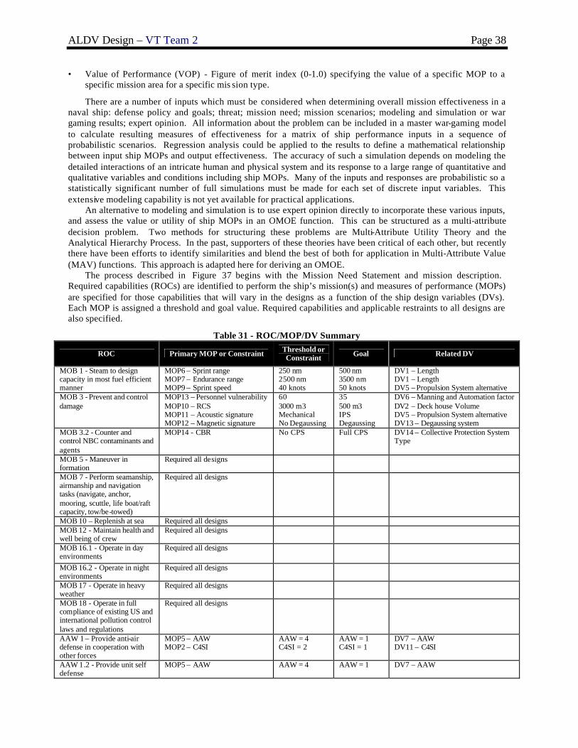
ALDV Design – VT Team 2 Page 38
• Value of Performance (VOP) - Figure of merit index (0-1.0) specifying the value of a specific MOP to a specific mission area for a specific mis sion type.
There are a number of inputs which must be considered when determining overall mission effectiveness in a naval ship: defense policy and goals; threat; mission need; mission scenarios; modeling and simulation or war gaming results; expert opinion. All information about the problem can be included in a master war-gaming model to calculate resulting measures of effectiveness for a matrix of ship performance inputs in a sequence of probabilistic scenarios. Regression analysis could be applied to the results to define a mathematical relationship between input ship MOPs and output effectiveness. The accuracy of such a simulation depends on modeling the detailed interactions of an intricate human and physical system and its response to a large range of quantitative and qualitative variables and conditions including ship MOPs. Many of the inputs and responses are probabilistic so a statistically significant number of full simulations must be made for each set of discrete input variables. This extensive modeling capability is not yet available for practical applications.
An alternative to modeling and simulation is to use expert opinion directly to incorporate these various inputs, and assess the value or utility of ship MOPs in an OMOE function. This can be structured as a multi-attribute decision problem. Two methods for structuring these problems are Multi-Attribute Utility Theory and the Analytical Hierarchy Process. In the past, supporters of these theories have been critical of each other, but recently there have been efforts to identify similarities and blend the best of both for application in Multi-Attribute Value (MAV) functions. This approach is adapted here for deriving an OMOE.
The process described in Figure 37 begins with the Mission Need Statement and mission description. Required capabilities (ROCs) are identified to perform the ship’s mission(s) and measures of performance (MOPs) are specified for those capabilities that will vary in the designs as a function of the ship design variables (DVs). Each MOP is assigned a threshold and goal value. Required capabilities and applicable restraints to all designs are also specified.
Table 31 - ROC/MOP/DV Summary
ROC Primary MOP or Constraint Threshold or Constraint Goal Related DV
MOB 1 - Steam to design capacity in most fuel efficient manner
MOP6 – Sprint range MOP7 – Endurance range MOP9 – Sprint speed
250 nm 2500 nm 40 knots
500 nm 3500 nm 50 knots
DV1 – Length DV1 – Length DV5 – Propulsion System alternative
MOB 3 - Prevent and control damage
MOP13 – Personnel vulnerability MOP10 – RCS MOP11 – Acoustic signature MOP12 – Magnetic signature
60 3000 m3 Mechanical No Degaussing
35 500 m3 IPS Degaussing
DV6 – Manning and Automation factor DV2 – Deck house Volume DV5 – Propulsion System alternative DV13 – Degaussing system
MOB 3.2 - Counter and control NBC contaminants and agents
MOP14 - CBR No CPS Full CPS DV14 – Collective Protection System Type
MOB 5 - Maneuver in formation
Required all designs
MOB 7 - Perform seamanship, airmanship and navigation tasks (navigate, anchor, mooring, scuttle, life boat/raft capacity, tow/be-towed)
Required all designs
MOB 10 – Replenish at sea Required all designs MOB 12 - Maintain health and well being of crew
Required all designs
MOB 16.1 - Operate in day environments
Required all designs
MOB 16.2 - Operate in night environments
Required all designs
MOB 17 - Operate in heavy weather
Required all designs
MOB 18 - Operate in full compliance of existing US and international pollution control laws and regulations
Required all designs
AAW 1 – Provide anti-air defense in cooperation with other forces
MOP5 – AAW MOP2 – C4SI
AAW = 4 C4SI = 2
AAW = 1 C4SI = 1
DV7 – AAW DV11 – C4SI
AAW 1.2 - Provide unit self defense
MOP5 – AAW AAW = 4 AAW = 1 DV7 – AAW

ALDV Design – VT Team 2 Page 39
ROC Primary MOP or Constraint Threshold or Constraint Goal Related DV
AAW 6 - Detect, identify and track air targets
MOP5 – AAW AAW = 4 AAW = 1 DV7 – AAW
AMW 6.1 – Conduct day helicopter, short/vertical take-off and landing
Required all designs
AMW 6.2 - Conduct night helicopter, short/vertical take-off and landing
Required all designs
AMW 6.3 – Conduct all-weather helo ops
Required all designs
AMW 6.6 – Conduct helo refueling
Required all designs
ASU 4.1 – Detect and track a surface target with radar
MOP2 – C4SI MOP3 – ASUW
C4SI = 2 ASUW= 4
C4SI = 1 ASUW = 1
DV11 – C4SI DV8 – ASUW
ASU 4.2 – Detect and track a surface target with sonar
MOP2 – C4SI MOP3 – ASUW
C4SI = 2 ASUW = 4
C4SI = 1 ASUW = 1
DV11 – C4SI DV8 – ASUW
ASU 6 - Disengage, evade and avoid surface attack
MOP9 – Sprint speed 40 knots 50 knots DV1 – Length DV5 – Propulsion System alternative
ASW 8 – Detect and track a submarine with sonar
MOP4 – ASW MOP2 – C4SI
ASW = 2 C4SI = 2
ASW = 1 C4SI = 1
DV9 – ASW DV11 – C4SI
ASW 10 – Disengage, evade and avoid submarine attack by employing countermeasures and evasion techniques
MOP4 – ASW MOP9 – Sprint Speed MOP6 – Sprint Range
ASW = 2 40 knots 250 nm
ASW = 1 50 knots 500 nm
DV9 – ASW DV1 – Length DV5 – Propulsion System alternative
MIW 1 – Conduct mine-hunting
MOP1 – MCM MOP2 – C4SI
MCM = 2
MCM = 1 DV10 – MCM DV11 – C4SI
MIW 4 – Conduct mine avoidance
MOP1 – MCM MCM = 2 MCM = 1 DV10 – MCM
MIW 6.7 – Maintain magnetic signature limits
MOP12 – Magnetic Signature No Yes DV13 – Degaussing System
CCC 1.6 – Provide a Helicopter Direction Center (HDC)
MOP2 – C4SI C4SI = 2 C4SI = 1 DV11 – C4SI
CCC 3 - Provide own unit CCC
MOP2 – C4SI C4SI = 2 C4SI = 1 DV11 – C4SI
CCC 4 - Maintain data link capability
MOP2 – C4SI C4SI = 2 C4SI = 1 DV11 – C4SI
LOG 1 – Conduct underway replenishment
Required all designs
LOG 2 – Transfer/receive cargo and personnel
Required all designs
LOG 4 – Support other ships and aircraft with supplies, fuel, ordnance, and other services
Required all designs 3 days 8 days
NCO 3 - Provide upkeep and maintenance of own unit
Required all designs
Table 31 summarizes the ROCs, DVs and MOPs as defined for ALDV. An Overall Measure of Effectiveness (OMOE) hierarchy is developed for the MOPs using the Analytical Hierarchy Process (AHP) to calculate MOP weights and Multi-Attribute Value Theory (MAVT) to develop individual MOP value functions. The result is a weighted overall effectiveness function (OMOE) that is used as one of three objectives in the multi-objective optimization. In the AHP, pair-wise comparison questionnaires are produced to seek expert and customer opinion required to calculate AHP weights. Values of Performance (VOP) functions, usually S-curves, are developed for each MOP and VOP values are calculated using these functions in the ship synthesis model. A particular VOP has a value of zero corresponding to the MOP threshold, and a value of 1.0 corresponding to the MOP goal.

ALDV Design – VT Team 2 Page 40
Figure 38 - OMOE Hierarchy
Table 32 - MOP Table
Primary MOP or Constraint Threshold or Constraint Goal Related DV
MOP1 – MCM (Table 17) MCM = 2 MCM = 1 DV10 - MCM
MOP2 - C4SI (Table 21) C4SI = 2 C4SI = 1 DV11 - C4SI
MOP3 – ASUW ( Table 18) ASUW = 4 ASUW = 1 DV8 - ASUW
MOP4 – ASW (Table 19) ASW = 2 ASW = 1 DV9 - ASW
MOP5 – AAW (Table 20) AAW = 4 AAW = 1 DV7 - AAW
MOP6 - Sprint Range 250 nm 500 nm DV1 - Length
MOP7 - Endurance Range 2500 nm 3500 nm DV1 - Length
MOP8 – Ship Provisions Duration 20 days 45 days DV15 - Provisions Duration
MOP9 - Sprint Speed 40 knots 50 knots DV5 - Propulsion System Type
MOP10 – RCS 300 m3 150 m3 DV2 - Deck house Volume
MOP11 - Acoustic Signature Mechanical IPS DV5 - Propulsion System Type MOP12 - Magnetic Signature No Degaussing Degaussing DV13 - Degaussing System
MOP13 - Personnel Vulnerability 60 35 DV6 - Manning and Automation Factor
MOP14 – CBR No CPS Full CPS DV14 - Collective Protection System Type
MOP15 - ALDS Combat Cargo 3 days 8 days DV15 - ALDS Mission Duration
Figure 38 illustrates the OMOE hierarchy for ALDV derived from Table 31. Separate hierarchies are developed for each type of mission for ALDV. MOPs are grouped under two missions (Combat Cargo, Disaster Relie f), which have four categories of MOPs (Self Defense, Mobility/Sustainability, Survivability, ALDS Cargo duration) with Mobility/Sustainability and ALDS Cargo duration being the only categories under Disaster Relief. MOPs are listed in Table 32. MOP weights are calculated using pair wise comparison as illustrated in Figure 39. Results are shown in Figure 40 and Table 33. MOP weights and value functions are finally assembled in a single OMOE function:
( )[ ] ( )iii
iii MOPVOPwMOPVOPgOMOE ∑==
Self Defense Survivability Mobility/Sustainability MOP 15 – ALDS Cargo
MOP 10 – RCS
MOP 5 – AAW
MOP 4 – ASW
MOP 3 – ASUW
MOP 2 – C4SI
MOP 1 – MCM
MOP 11 – Acoustic
MOP 12 – Magnetic
MOP 13 – Personnel
MOP 13 – CBR
MOP 6 – Sprint Range
MOP 7 – End Range
MOP 8 – Provisions
MOP 9 – Sprint Speed
Combat Cargo Disaster Relief
Maximize Overall Measure of Effectiveness

ALDV Design – VT Team 2 Page 41
Figure 39 - Example of AHP Pair-wise Comparison
Figure 40 - Bar Chart Showing MOP Weights
Table 33 - MOP Weights
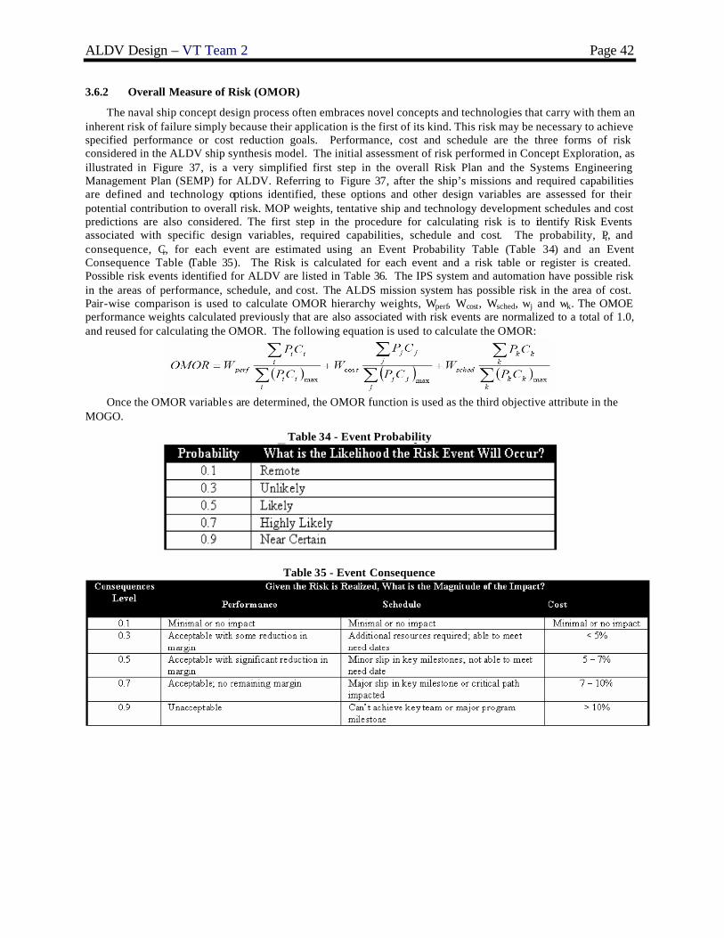
ALDV Design – VT Team 2 Page 42
3.6.2 Overall Measure of Risk (OMOR)
The naval ship concept design process often embraces novel concepts and technologies that carry with them an inherent risk of failure simply because their application is the first of its kind. This risk may be necessary to achieve specified performance or cost reduction goals. Performance, cost and schedule are the three forms of risk considered in the ALDV ship synthesis model. The initial assessment of risk performed in Concept Exploration, as illustrated in Figure 37, is a very simplified first step in the overall Risk Plan and the Systems Engineering Management Plan (SEMP) for ALDV. Referring to Figure 37, after the ship’s missions and required capabilities are defined and technology options identified, these options and other design variables are assessed for their potential contribution to overall risk. MOP weights, tentative ship and technology development schedules and cost predictions are also considered. The first step in the procedure for calculating risk is to identify Risk Events associated with specific design variables, required capabilities, schedule and cost. The probability, Pi, and consequence, Ci, for each event are estimated using an Event Probability Table (Table 34) and an Event Consequence Table (Table 35). The Risk is calculated for each event and a risk table or register is created. Possible risk events identified for ALDV are listed in Table 36. The IPS system and automation have possible risk in the areas of performance, schedule, and cost. The ALDS mission system has possible risk in the area of cost. Pair-wise comparison is used to calculate OMOR hierarchy weights, Wperf, Wcost, Wsched, wj and wk. The OMOE performance weights calculated previously that are also associated with risk events are normalized to a total of 1.0, and reused for calculating the OMOR. The following equation is used to calculate the OMOR:
Once the OMOR variables are determined, the OMOR function is used as the third objective attribute in the
MOGO.
Table 34 - Event Probability
Table 35 - Event Consequence

ALDV Design – VT Team 2 Page 43
Table 36 - ALDV Risk Register
3.6.3 Cost
ALDV construction costs are estimated for each SWBS group using complexity-adjusted weight-based equations. Figure 41 illustrates acquisition cost components calculated in the model. The Basic Cost of Construction (BCC) is the sum of all SWBS group costs. Ship price includes profit. In naval ships, the Total Shipbuilder Portion is the sum of the projected cost of change orders and the BCC. The Total Government Portion is the sum of the cost of Government Furnished Material (GFM) and Program Managers Growth. The Total End Cost is the Sum of the Total Shipbuilder Portion and the Total Government Portion. ALDV life cycle cost includes construction costs plus selected operating and support costs (fuel and manning).
Other Support
Program Manager'sGrowth
Payload GFE
HM&E GFE
OutfittingCost
GovernmentCost
MarginCost
Integration andEngineering
Ship Assemblyand Support
OtherSWBS Costs
Basic Cost ofConstruction (BCC)
Profit
Lead Ship Price Change Orders
ShipbuilderCost
Total End Cost Post-DeliveryCost (PSA)
Total Lead ShipAquisition Cost
Figure 41 - Naval Ship Acquisition Cost Components [3]

ALDV Design – VT Team 2 Page 44
3.7 Optimization Results
Figure 42 shows the final effectiveness-cost-risk non-dominated frontier generated by the multi-objective genetic optimization (MOGO). Each point on the frontier represents objective attribute values for a feasible non-dominated ship design. All feasible designs are represented in Figure 42 with cost and effectiveness on the axes, and risk indicated by color as low (OMOR<0.25), low medium (0.25<OMOR<0.32), medium (0.32<OMOR<0.40), medium high (0.40<OMOR<0.54), or high (OMOR>0.55). The most interesting design possibilities for the customer are those that occur at the extremes of the frontier and at “knees” in the curve. The designs located at the “knees” are considered because they tend to have a sharp increase in effectiveness with a minimal increase in cost at a particular level of risk. The measures of performance that drive the effectiveness the most are cargo carrying capacity (MOP 15 ALDS cargo) and sprint speed (MOP 9 Sprint Speed) as they have the highest values of performance.
The two most attractive designs are numbers 16 and 28 as they are distinct “knees” for low risk and high risk respectively. High-risk designs (i.e. 28) are normally not attractive to the customer, but often provide beneficial educational gains as newer systems and technologies are considered. Design 16 shown in Figure 42 was assigned to Team 2.
0
0.1
0.2
0.3
0.4
0.5
0.6
400 500 600 700
Average Follow Ship Cost ($M)
OM
OE
Low Risk
LowMedium RiskMedium RiskMedium High Risk
High Risk
Figure 42 - Non-Dominated Frontier based on Follow Ship Acquisition Cost
3.8 Design 16 - Baseline Concept Design
Design 16 is a relatively low risk and low cost non-dominated ship design identified by MOGO, resulting in a lower overall measure of effectiveness. The low risk of this design is due to low levels of automation and a mechanical drive propulsion system. The low cost and effectiveness are a result of this design only supporting four ALDS mission days. The baseline ship characteristics are summarized in the following tables. Table 37 lists the design variables, the ranges considered for ALDV, and the values selected for Design 16. Table 38 lists the weights and vertical centers of gravity by SWBS group with margins. Table 39 reviews the arrangeable area. Table 40 is an electric power summary by SWBS group. Table 41 lists the values given to each MOP in determining the overall measure of effectiveness. Table 42 contains the principle characteristics and requirements of the ship design. This includes overall ship dimensions, propulsion and combat system descriptions, crew member breakdown, and cost thresholds. The weight margin for this design was reduced to 1% to decrease draft, reduce resistance and improve sustained speed. This margin should be increased to 5-10% in concept development.
16
28

ALDV Design – VT Team 2 Page 45
Table 37 - Design Variables Summary Design
Variable Description Trade-off Range ALDV-16
Design Values DV 1 Length 150-200 m 176 m DV 2 Deck house Volume 150-300 m3 185 m3 DV 3 Deck house Material Type 1. steel
2. aluminum 1. steel
DV 4 Ballast Type 0. separate ballast 1. compensated fuel system
0. separate (clean) ballast
DV 5 Propulsion System Type 1. 2xLM2500+, 4x3500kw SSGTG, 2x225SII waterjets, mech. 2. 2xMT30, 4x3500kw SSGTG, 2x225SII waterjets, mech. 3. 3xMT30, 4x3500kw SSGTG, 3x225SII waterjets, mech. 4. 2xLM2500+, 5x3500kw SSGTG, 2x225SII waterjets, IPS & mech. 5. 2xMT30, 5x3500kw SSGTG, 2x225SII waterjets, IPS & mech. 6. 3xMT30, 5x3500kw SSGTG, 3x225SII waterjets, IPS & mech. 7. 2xLM2500+, 2x3500kw SSGTG, 2x225SII waterjets, IPS 8. 2xMT30, 2x3500kw SSGTG, 2x225SII waterjets, IPS 9. 3x MT30, 2x3500kw SSGTG, 3x225SII waterjets, IPS
2. 2xMT30, 4x3500kw SSGTG, 2x225SII waterjets, mechanical drive
DV 6 Manning and Automation Factor 0.5-1.0 1.0 DV 7 AAW Alternative 1 (goal), 2, 3, 4(threshold) 4 (threshold) DV 8 ASUW Alternative 1 (goal), 2, 3 (threshold) 3 (threshold) DV 9 ASW Alternative 1 (goal), 2 (t hreshold) 1 (goal) DV 10 MCM Alternative 1 (goal), 2 (t hreshold) 2 (threshold) DV 11 C4I Alternative 1 (goal), 2 (t hreshold) 1 (goal) DV 12 LAMPS 1 (goal), 2, 3, 4 (threshold) 4 (threshold) DV 13 Degaussing System 0. none
1. degaussing system 1. degaussing system
DV 14 Collective Protection System 0. none 1. partial 2. full
2. full
DV 15 Provisions Duration 20 – 45 days 29 days DV 16 ALDS Mission Duration 3 – 8 days 4 days
Table 38 - Concept Exploration Weights and Vertical Center of Gravity Summary Group Weight VCG
SWBS 100 1354 MT 6.73 m SWBS 200 449 MT 3.32 m SWBS 300 228 MT 6.27 m SWBS 400 133 MT 10.02 m SWBS 500 448 MT 4.20 m SWBS 600 149 MT 7.11 m SWBS 700 6 MT 2.89 m Lightship w/Margin 2822 MT 4.71 m Loads 2528 MT 7.44 m Full Load w/Margin 5350 MT 6.00 m
Table 39 - Concept Exploration Area Summary Area Required Available
Total-Arrangeable 4259.7 m2 4093.8 m2
(within 5% tolerance of required)
Hull 4073.2 m2 3908.8 m2 Deck House 186.6 m2 185.0 m2

ALDV Design – VT Team 2 Page 46
Table 40 - Concept Exploration Electric Power Summary Group Description Power SWBS 200 Propulsion 312 kW SWBS 300 Electric Plant, Lighting 132 kW SWBS 430, 475 Miscellaneous 101 kW SWBS 521 Firemain 60 kW SWBS 540 Fuel Handling 96 kW SWBS 530, 550 Miscellaneous Auxiliary 29 kW SWBS 561 Steering 75 kW SWBS 600 Services 18 kW CPS CPS 167 kW KWNP Non-Payload Functional Load 823 kW KWMFLM Max. Functional Load w/Margins 1887 kW KW24 24 Hour Electrical Load 1101 kW
Table 41 - MOP/ VOP/ OMOE/ OMOR Summary – Basis of ORD TPMs
MOP # Description MOP Value Achieved
VOP (Value of Performance)
MOP 1 MCM Option 2 (threshold) 0.0 MOP 2 C4SI Option 1 (goal) 1.0 MOP 3 ASUW Option 3 (threshold) 0.0 MOP 4 ASW Option 1 w/o LAMPS 0.2 MOP 5 AAW Option 4 (threshold) 0.0 MOP 6 Sprint Range 1145. 1.0 MOP 7 Endurance Range 6485 1.0 MOP 8 Ship Provisions Duration 29 days 0.26 MOP 9 Sprint Speed 38.5 (within 5%) 0.0
MOP 10 RCS 185.0 0.26 MOP 11 Acoustic Signature Mechanical drive 0.0 MOP 12 Magnetic Signature Degaussing 1.0 MOP 13 Personnel Vulnerability Manning = 45 0.6 MOP 14 CBR Full CPS 1.0 MOP 15 ALDS Combat Cargo 4 days 0.1 OMOE Overall Measure of Effectiveness 0.216 OMOR Overall Measure of Risk 0.202

ALDV Design – VT Team 2 Page 47
Table 42 - Concept Exploration Baseline Design Principal Characteristics Characteristic Baseline Value
Hullform Trimaran
∆ (MT) 5350
LWL (m) 176
Beam (m) 28.3
Draft (m) 4.78
D10 (m) 15.4
Displacement to Length Ratio, C∆L (lton/ft) 9.45
Beam to Draft Ratio, CBT 5.91
W1 (MT) 1354
W2 (MT) 449
W3 (MT) 228
W4 (MT) 133
W5 (MT) 448
W6 (MT) 149
W7 (MT) 6
Lightship ∆ (MT) w/margin 2822
Loads (MT) 2528
KG (m) 6.00
GM/B 0.130
Propulsion System Mechanical Driv e w/ Epicyclic Gears: 2 x 300SII Waterjets 2 x MT30 4 x 3500 KW SSGTG
Engine inlet and exhaust Side
MCM system Degaussing
ASW system AN/SLQ-25 NIXIE
ASUW system Surface Search Radar - AN/SPS-73 DDG51 Small Arms & Pyro Storage 1 x 7M RHIB
AAW system MK XII AIMS IFF Combat DF
LAMPS system LAMPS MKIII Aviation Fuel System SINGLE SH-60 – Mission Fuel
C4I system DDG51 Navigation System Communication Suite Level A
Average Deck Height (m) 2.6
Total Officers 6
Total Enlisted 39
Total Manning 45
Follow Ship Acquisition Cost $467.82 Million
Life Cycle Cost $599.79 Million

ALDV Design – VT Team 2 Page 48
4 Concept Development (Feasibility Study)
Concept Development of ALDV follows the design spiral, Figure 3, in sequence after Concept Exploration. In Concept Development the general concepts for the hull, systems , and arrangements are developed. These general concepts are refined into specific systems and subsystems that meet the ORD requirements of ALDV. Design risk is reduced by this analysis and parametrics used in Concept Exploration are validated.
4.1 General Arrangement and Mission Operations Concept (Cartoon)
As a preliminary step in finalizing hullform geometry, deck house geometry, and all general arrangements, an arrangement cartoon was developed for areas supporting mission operations, propulsion, and other critical constrained functions. ALDS mission operation and support were critical considerations throughout arrangement development. Arrangement of the ALDS cargo, onboard glider assembly system, and mechanical launch system is vital in the effectiveness of the ALDS system. The dimensions of ALDS system components were based on the most accurate data available and differ slightly than math model initial estimates. Optimization using more accurate ALDS dimensions might prove to be useful in future designs. These dimensions were used to arrange the initial ALDS system, with the ALDS onboard glider assembly system located above the cross-deck. A scaled layout of this ALDS assembly room is depicted in Figure 43, Figure 44 shows the initial profile arrangement, and Figure 45 shows the initial topside arrangement. The deck house is designed with 10 degree angled sides to minimize radar cross section, and it is located above the fore end of the mission bay. The helo pad, used to support V-22 and LAMPS refueling operations, is also located above the mission bay.
Figure 43 - Mission Bay (ALDS Assembly Room)
Figure 44 - Profile (Cartoon)
Figure 45 - Topside Arrangement

ALDV Design – VT Team 2 Page 49
4.1.1 Mission Operations
ALDS consists of three major components that affect arrangement development: cargo stores, glider assembly, and mechanical launch. It is essential to locate the onboard glider assembly system (Figure 43) above the cross-deck due to the large arrangeable area required to store four days of glider components and the necessary maintenance, support, and assembly equipment. Mechanical launch is achieved through the use of a Linear Induction Motor (LIM) launch tube. The location of the LIM launch tube is critical in arrangement development due to its large length and curvature requirements. The beginning of the LIM launch tube was initially located directly above the inner bottom in order to provide a gradual bank for the gliders to climb and launch at the required 30 degree angle at the bow (See Figure 44). The LIM is surrounded port and starboard by tankage to utilize potential unarrangeable area. A specially designed elevator will also be installed to transport the ALDS gliders to the LIM launch tube. The ALDS dry cargo stores and magazines were placed below the damage control deck and above the LIM launch tube. Cargo elevators will be installed to transport cargo to the ALDS assembly room.
4.1.2 Machinery Room Arrangements
ALDV-16 has two main machinery rooms (MMR1and MMR2) and an auxiliary machinery room (AMR). Both MMRs contain one MT30 gas turbine and one 3500kw SSGTG, and the AMR contains two 3500kw SSGTGs. The MT30 gas turbines are used to power two 300SII Kamewa Waterjets. Both MMRs are located aft of midships with MMR1 slightly forward of MMR2. MMRs are located aft to reduce shaft length and to avoid interference with the LIM. Main engines use side air intakes and exhaust to avoid area losses and protrusions on the mission bay deck that would exist with standard topside exhaust. The AMR is located forward of midships to aid in stability and survivability.
4.2 Hullform and Deck House
4.2.1 Hullform
The parent hullform used in Concept Exploration is based on a variation of the R/V Triton hullform. The parent was modified in Concept Development to conform to the geometric dimensions specified in the optimization and provide necessary ALDV characteristics. Modifications included lengthening the center and side hulls by adding parallel midbody, and increasing the transom width to better accommodate waterjets. The deck house was modified to meet volume requirements specified by the optimization. A 10 degree tumblehome was added to reduce radar cross section. Table 43 compares the parent hullform to the ALDV-16 baseline hullform.
Table 43 - ALDV-16 Hullform Characteristics
Parent Hull ALDV-16 Baseline
LWL 126 m 176 m B 24.9 m 28.3 m T 4.21 m 4.78 m
D10 10.7 m 15.4 m
∆ 2825 MT 5350 MT
An isometric view, profile view, waterline view, and body plan view are shown in Figure 46, Figure 47, Figure 48 and Figure 49 respectively. The floodable length curve for ALDV is shown in Figure 50, and the general curves of form are shown in Figure 51.
ALDV-16 is a wave piercing tumblehome (WPTH) hullform. The 10 degree tumblehome in the center hull aids in reducing radar cross section (RCS), and the wave piercing bow, raked by 47 degrees, helps to diminish wave resistance. This 47 degree angle was estimated based on expert opinion and comparisons to the parent hull. All structure above the waterline, including the cross-deck structure, deck house, pilot house, and transom have flat plating slanted at 10 degrees to further reduce RCS. The outboard sides of the side hulls are also designed with flat plating at a 10 degree angle to reduce RCS. The ALDV-16 design also features a hard chine on the center hull just above the waterline. This allows the center hull above the waterline to be built with flat or single curvature plating, enhancing the producibility of the design. The liberal use of flat plating in design of the cross-deck structure, deck house, pilot house, transom, and hulls also helps to make the design more producible.

ALDV Design – VT Team 2 Page 50
Figure 46 - ALDV-16 Isometric View
Figure 47 - ALDV-16 Profile View
Figure 48 - ALDV-16 Waterline View
47° Raked Wake Piercing Bow
10° Raked Transom

ALDV Design – VT Team 2 Page 51
Figure 49 - ALDV-16 Body Plan
Figure 50 - Floodable Length Curve
Pilot House
Deck House
Crossdeck Structure
10° Tumblehome

ALDV Design – VT Team 2 Page 52
0
2
4
6
8
10
12
14
0 50 100 150 200 250
Dra
ft (m
)
Disp (MT*1000) LCB (m-Aft FP) LCF (m-Aft FP) MT1 (m-MT/cm) KMt (m)
Figure 51 - Curves of Form
4.2.2 Deck House
A profile view of the deck and pilot house is shown in Figure 52. The deck house contains the radio room, a cabin for the CO, and an aviation office which directs V-22 refueling operations. Above the deck house is a pilot house and chart room. Aft of the chart room is a magazine for a CIWS placed above the pilot house. It should be noted that the Mission Bay volume is included in all deck house volume calculations.
An Advanced Enclosed Mast/Sensor (AEM/S) is also placed above the pilot house (Figure 53). It has an octagonal footprint of 65 m2 and all sides flare inward at 10 degrees to reduce RCS. The AEM/S structure contains the SPS-73 surface search and navigational radar, and the external shell is constructed with an advanced hybrid frequency selective surface that allows the ALDV-16 radar in and out, but blocks foreign radar signals [1].
Figure 52 - Deck House and Pilot House Profile View
Deck House Pilot House

ALDV Design – VT Team 2 Page 53
Figure 53 - Advanced Enclosed Mast/Sensor (AEM/S)
4.3 Structural Design and Analysis
The structural design process for ALDV-16 is illustrated in Figure 54.
Geometry
Components / Materials
Loads
StressesModes of
Failure Strength
Scantling Iteration
Figure 54 - Structural Design Process
4.3.1 Geometry, Components, and Materials
The geometry is modeled in MAESTRO, a coarse-mesh finite element solver with the additional ability to assess individual failure modes. After assessing adequacy, a few iterations of scantling modifications to correct inadequacies and reduce weight were performed.
A three-dimensional mesh of the ALDV-16 hullform is created in FASTSHIP. This mesh is imported into MAESTRO. The coordinate axes are adjusted such that the origin is coincident with the aft perpendicular of the imported mesh and the X-axis is positive in the forward direction, the Y-axis is positive vertically upward, and the Z-axis is positive in the starboard direction. Using the vertices of the imported mesh as reference points, the hull panel endpoints are created in MAESTRO. Figure 56 shows the completed MAESTRO model.
ALDV-16 is a longitudinally-stiffened ship with transverse frames every 2.5 meters. Initial scantlings are chosen based on similar designs. Figure 55 shows the midship section, and Figure 57 shows the ALDV-16 midship module. The structure is similar to a traditional single hull design with decks and side shells supported by longitudinal stiffeners, girders, and transverse frames with tee-shaped cross-sections. Deep deck beams and pillars are used to support the flight deck. A transverse web cross-structure is used to connect the center hull to the side hulls and resist transverse loads. This structure also provides space for piping and wire ways.
Figure 58 shows the interior of the MAESTRO model. ALDV-16 has one full deck above the damage control deck and two platform decks below the damage control deck. The platform decks are not continuous through the machinery rooms. There is one centerline bulkhead in the ship, separating the waterjets and shafts for survivability. The model includes five substructures, each with five individual modules. ALDV-16 is modeled such that each module spans the entire beam of the ship.
St4027 (ABS AH36) steel was selected for the hull plating, decks, transverse bulkheads, etc., as well as for the girders, frames, and stiffeners. A standard catalog of shapes and plate thicknesses was developed using I-Ts, Ts, and a limited number of fabricated shapes. The catalog was kept as small as possible to maximize producibility.

ALDV Design – VT Team 2 Page 54
Figure 55 - ALDV-16 Midship Section (St4027 = ABS AH36 steel)
4.3.2 Loads
Load cases were applied in MAESTRO using equivalent waves to meet or exceed longitudinal bending moment requirements calculated using the ABS Guide for Building and Classing High Speed Naval Craft, 2003 (multi-hull ships). ABS-required bending moments and other loads and requirements are listed in Table 44. The weight distribution curve and still water bending moment curve developed for ALDV-16 are shown in Figure 59 and Figure 60 respectively. Equivalent wave hogging and sagging load cases, and transverse bending moments were evaluated. The equivalent bending moment curves for the longitudinal bending cases are shown in Figure 60 and Figure 61 respectively. The required transverse bending moment is achieved by changing the equivalent wave yaw angle by 90 degrees as shown in Figure 63.
4.3.3 Adequacy
MAESTRO calculates stresses for each load case and compares them to limit state values for various failure modes. Stress divided by failure stress for various modes of failure results in a strength ratio, r. This value can range between zero and infinity. An adequacy parameter is defined as: (1 – r)/(1 + r). This parameter is always between negative one and positive one. A negative adequacy parameter indicates that an element is inadequate, a positive value indicates that it is over-designed, and a value of zero indicates that it exactly meets the requirement with a specified factor of safety. At this level of analysis, the main objective is to make as many of the adequacy parameters as close to zero as possible while staying on the positive side. In a more detailed analysis, the objective

ALDV Design – VT Team 2 Page 55
would be to adjust the scantlings throughout the ship such that all adequacy parameters equal zero, again staying on the positive side. A safety factor of 1.25 is used for serviceability limit states and 1.5 for collapse limit states. ALDV-16 adequacy parameters, Figure 64 and Figure 65, show the minimum values for plate and beam failure modes for all load cases.
Figure 56 - ALDV-16 MAESTRO Model
Figure 57 - ALDV-16 MAESTRO Model (Midship Module)

ALDV Design – VT Team 2 Page 56
Figure 58 - Interior of ALDV-16 MAESTRO Model
Table 44 - ABS Load Requirements for ALDV-16 -1253584 kN-m1074852 kN-m
0 kN-m747877 kN-m
2289648 kN-m2289648 kN-m
420525 kN-m2819520 kN-m
43 N/m2
24 N/m2
5 N/m2
129568 cm2-m
691028 cm2-mRequired Moment of Inertia at Midship
Required Section Modulus at MidshipInternal Deck LoadsWeather Deck Loads (25m aft of FP to AP)Weather Deck Loads (0-25m aft of FP)
Torsional Bending MomentTransverse Bending MomentLargest Combine Longitudinal Bending Moment
Wave Sagging Longitudinal Bending Moment
Slamming and Dynamic Longitudinal Bending MomentStill Water Hogging Longitudinal Bending MomentStill Water Sagging Longitudinal Bending MomentWave Hogging Longitudinal Bending Moment
Figure 59 - Full Load Stillwater Weight Distribution in MAESTRO
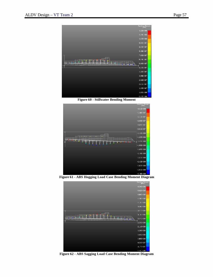
ALDV Design – VT Team 2 Page 57
Figure 60 - Stillwater Bending Moment
Figure 61 - ABS Hogging Load Case Bending Moment Diagram
Figure 62 - ABS Sagging Load Case Bending Moment Diagram

ALDV Design – VT Team 2 Page 58
Figure 63 - Defor mation (Exaggerated) Modeling Transverse Bending Moment
Figure 64 - Plate Adequacy (Minimum values for all load cases)
Figure 65 - Beam Adequacy (Minimum values for all load cases)

ALDV Design – VT Team 2 Page 59
4.4 Power and Propulsion
ALDV-16 uses a mechanical drive system for propulsion. The mechanical drive system includes two 300SII Kamewa Waterjets driven by two MT30 gas turbines with epicyclic reduction gears and four 3500kw SSGTGs.
4.4.1 Resistance
Resistance, speed, and power calculations are performed using NAVCAD software. NAVCAD requires input of hull characteristics, speed, wind and wave conditions, propulsor (waterjet) characteristics, and engine characteristics. The Holtrop-Mennen method is used for a preliminary estimate of ALDV-16 resistance. Speeds between 14 and 43 knots are considered. NAVCAD does not have the direct capability of performing these calculations for a trimaran, so both the center hull and side hulls are modeled as monohulls with a 10% resistance margin added for multi-hull interaction. An additional 10% margin is added for the endurance speed/fuel calculation and a 25% margin is added for the sustained speed calculation. Figure 66 is the resulting resistance vs. speed curve. Figure 67 is the power vs. speed curve.
Figure 66 - Resistance vs. Speed Curve
Figure 67 - Power vs. Speed Curve (per shaft)

ALDV Design – VT Team 2 Page 60
4.4.2 Propulsion
Two 300SII Kamewa Waterjets, Figure 12, are used for propulsion in ALDV-16. Each has an impeller diameter of 3.0 meters and a nozzle diameter of 2.0 meters. Maximum impeller speed is 300 RPM, and the maximum power is 32 MW. Figure 13 and Figure 14 provide performance data for this family of waterjets. A waterjet model was created in NAVCAD, Figure 68, using this data.
Figure 68 - 300SII Kamewa Waterjet file in NAVCAD
Each waterjet is driven by an MT30 gas turbine with epicyclic reduction gears operating with a reduction gear ratio of 17.85. An overall transmission efficiency of 0.98 is assumed. Each MT30 has a maximum speed of 3650 RPM. An engine performance mo del, Figure 69, was generated in NAVCAD using data from the MT30 performance map.
Figure 69 - MT30 engine file in NAVCAD

ALDV Design – VT Team 2 Page 61
Figure 70 shows shaft propulsion power vs. engine speed (RGratio = 17.85) superimposed on the engine performance (power vs. speed) curve with points indicating resulting ship speed. This is the ship power vs. speed curve including the 25% sustained speed margin. The reduction gear ratio is adjusted to provide a maximum sustained speed of 45.6 knots. A more complete propulsion system description and arrangements are provided in Sections 4.5 and 4.7.2.
Figure 70 - Propulsion SHP vs. Engine S peed w/ Sustained S peed Power Margin
Figure 71 and Figure 72 show propulsion efficiency and total power available versus engine speed. Figure 73 shows fuel consumption per engine with a 10% endurance power margin versus ship speed.
Figure 71 - Propulsion Efficiency (PC) vs. Speed

ALDV Design – VT Team 2 Page 62
Figure 72 - Total Engine Power vs. Engine Speed (2 engines)
Figure 73 - Fuel Consumption vs. Ship Speed (per engine)
4.4.3 Electric Load Analysis (ELA)
Electric power requirements for SWBS groups 100 through 700 equipment and machinery are summarized in the Electric Load Analysis Summary, Table 45. Load factors are used to estimate the electric power requirement for each component in each of five operating conditions, including Condition 1, loiter, cruise, in-port, anchor, and emergency. The SSGTGs are lightly loaded in all conditions. 1500kW SSDGs will be considered in subsequent design iterations.

ALDV Design – VT Team 2 Page 63
Table 45 - Electric Load Analysis Summary
SWBS Description
Average Connected Power (kW)
ALDV Launch
(kW) Cruise (kW)
Inport (kW)
Anchor (kW)
Emergency (kW)
200 Propulsion 312 312 312 0 0 0 560 Ship Control 75 75 75 0 0 0 300 Electric 132 132 132 132 132 132 510 CPS 167 167 167 167 167 0 490 Miscellaneous 101 101 101 101 101 0 520 Firemain 60 60 60 60 60 60 540 Fuel Handling 96 96 96 96 96 0 500 Auxillary 29 29 29 29 29 0 600 Services 18 18 18 18 18 0 510 HVAC 800 800 800 800 800 800 580 ALDS System 795 795 0 0 0 0
470 Payload 88 88 0 0 0 0
Total Required 3473 2673 1790 1403 1403 992 Available kW 15556 7778 7778 3889 3889 3889 Online SSGTGs 4 2 2 1 1 1
4.4.4 Endurance Fuel Calculation
A fuel calculation was performed for endurance range and sprint range in accordance with DDS 200-1. The fuel calculations are shown in Figure 74 and Figure 75. Results indicate an endurance range of 4687 nm and a sprint range of 1477 nm, exceeding endurance and sprint range thresholds specified in the ORD.
Figure 74 - Fuel Calculations for Sprint and Endurance S peeds

ALDV Design – VT Team 2 Page 64
Figure 75 - Fuel Calculations for Sprint and Endurance S peeds (cont)
4.5 Mechanical and Electrical Systems
Mechanical and electrical systems are selected based on mission requirements, standard naval requirements for combat ships, and expert opinion. The Machinery Equipment List (MEL) of major mechanical and electrical systems for ALDV-16 includes quantities, dimensions, weights, and locations. The complete MEL is provided in Appendix D. Partial MELs are provided in Table 48 and Table 49. The major components of the mechanical and electrical systems and the methods used to size them are described in the following two subsections. The arrangement of these systems is detailed in Section 4.7.2.
4.5.1 Ship Service Powe r
Figure 76 shows the one-line diagram for ship service power. Four Ship Service Gas Turbine Generators (SSGTGs) provide 460 volt, 60 Hz electric power to the primary switchboards. This power may be routed to ship service loads through Power Conversion Modules and the port and starboard zonal buses. The generator sets each have a generator control panel for local control, and they may be automatically or manually started both locally and

ALDV Design – VT Team 2 Page 65
remotely from the EOS. Automatic paralleling and load sharing capability are provided for each set. The glider-launch LIM Power Storage Unit(s) have redundant power converters fed from all three switchboards.
Figure 76 - One-Line Electrical Diagram
4.5.2 Service and Auxiliary Systems
Tanks for lube oil, fuel oil, and waste oil are sized based on requirements from the Ship Synthesis model. Equipment size and capacity are based on similar ship designs. Most equipment is located in either the MMRs or AMRs. Fuel and lube oil purifiers are sized relative to the fuel and oil consumption of each engine, and they are located in MMR1 and AMR2. Two 76 m3 per day distillers are used to produce potable water from seawater. They are located in the AC and Refrigeration room. For ALDV-16, the volume of the potable water tank is 8 m3. This supports an allotment of 0.16 m3
of water per person per day for the 45 person crew. Distillate pumps are used to pump water from the distillers to the potable water tanks. Potable water pumps are used to pressurize the potable water system from the tanks. Four air conditioning plants and two refrigeration plants are required for ALDV-16. The air conditioning plants are 150 tons each and sized based on crew size and arrangeable area requirements. The refrigeration plants and three of the air conditioning plants are located in the AC and Refrigeration room, with the remaining air conditioning plant located in AMR1. JP-5 pumps and filters are located in the JP-5 pump rooms.
4.5.3 Ship Service Electrical Distribution
Ship service power is distributed from any of the three main switchboards via a zonal bus, as shown in Figure 76. Power from the main switchboards is supplied to the main switchboards by the four 3500kw SSGTGs. The ship is divided into five CPS and Electrical Distribution Zones. Electric power is taken from the zonal buses in each zone through the Power Conversion Modules. If there is a vital system in a zone, it draws power from both the port and starboard buses through a Power Conversion Module and an ABT, which is an automated switch to either bus in case of power loss of one of the zonal buses. Zonal systems are also used for the ship’s firemain system and Collective Protection System. The firemain is located on the Damage Control (DC) Deck with fire pumps in each zone. CPS zones are separated by air locks with airlocks on all external accesses. The glider-launch LIM Power Storage Unit(s) have redundant power converters fed directly from all three switchboards (average 750 kW).

ALDV Design – VT Team 2 Page 66
4.6 Manning
ALDV-16 utilizes automation and unmanned systems to reduce manning from current Navy standards. ALDV-16 has a total crew of 45, composed of one CO, one XO, four department heads, 15 CPOs, and 24 enlisted. Technologies such as GPS, automated route planning, electronic charting and navigation, collision avoidance, and electronic log keeping enable ALDV-16 to operate with minimal crew requirements. High levels of automation and advanced technology necessitate that this crew be highly trained and versatile. The original ALDV-16 manning estimate was made using the ship synthesis model. These estimates were based on regression equations related to ship size, ship displacement, and propulsion systems. Existing naval ship data was used to refine these estimates. In Concept Development, total crew is organized by department as presented in Figure 77. A manning summary is also presented in Table 46. ALDV-16 manning organization consists of four departments: Operations, ALDS/Weapons, Engineering, and Supply. Note that the Weapons Department is combined with ALDS operations because ALDV-16 is limited to minimal self defense combat systems .
Table 46 - Manning Summary
Departments Division Officers CPO Enlisted Total Department
CO/XO 2 2 Department Heads 4
Operations Communications 1 1 2 13 Navigation and Control 1 3 Electronic Repair 1 1
CIC, EW, Intelligence 1 2 ALDS/Weapons Weapons/Defense 1 1 1 10
ALDS Cargo Operations 1 1 ALDS Glider Assembly 1 2 LIM Operation 1 1
Engineering Main Propulsion 1 1 2 12 Electrical/IC 1 2 Auxiliaries 1 1 Repair/DC 1 2
Supply Stores 1 1 1 8 Material/Repair 1 1 Mess 1 2 Total Crew 6 15 24 45
CO
XO
Operations Department
ALDS/WeaponsDepartment
EngineeringDepartment
SupplyDepartment
Communications
Navigation andShip Control
ElectronicRepair
CIC, EW,Intelligence
Weapons/Defense
ALDS Cargo Operations
ALDS Glider Assembly
LIM Operation
Main Propulsion
Electrical & IC
Auxiliaries
Repair/DC
Stores
Material, Repair
Mess
Figure 77 - Manning Organization

ALDV Design – VT Team 2 Page 67
4.6.1 Operations Department
The Operations Department is in charge of radio operations, communications, watch standing, and navigation duties. This department is also tasked with medical operations and maintenance of electronic and communications equipment. This department is assigned one department head, four CPOs (one per division), and seven enlisted.
The Operations Depart ment consists of four divisions: Communications, Navigation and Ship Control, Electronic Repair, and CIC, EW, and Intelligence. The Communications division is responsible for sending, relaying, and interpreting electronic information. The Navigation and Ship Control division is tasked with navigating the ship according to the specified mission. The Electronic Repair division is responsible for the maintenance of all electronic equipment. The CIC, EW, and Intelligence division is responsible for gathering intelligence for the CO, electronic warfare, and manning the bridge.
4.6.2 ALDS/Weapons Department
The ALDS/Weapons Department is responsible for ALDS cargo operations, glider assembly, launch and control, and onboard combat system use and maintenance. This department is assigned one department head, four CPOs (one per division), and six enlisted.
The ALDS/Weapons Depart ment consists of four divisions: Weapons/Defense, ALDS Cargo Operations, ALDS Glider Assembly, and LIM Operation. The Weapons/Defense division is responsible for CIWS operations and weapon maintenance. The ALDS Cargo Operations division is in charge of the dry cargo, wet cargo, and ammunition cargo logistics. The ALDS Glider Assembly division is tasked with glider assembly operations within the mission bay. The LIM Operation division is responsible for the operation and maintenance of the LIM launch tube and associated equipment.
4.6.3 Engineering Department
The Engineering Department is responsible for the mechanical and electrical systems onboard the ship. This includes operation and support of two MT30 gas turbines, four 3500kw SSGTGs, and other mechanical and electrical equipment. This department is assigned one department head, four CPOs (one per division), and seven enlisted.
The Engineering Depart ment consists of four divisions: Main Propulsion, Electrical and IC, Auxiliaries, and Repair/Damage Control. The Main Propulsion division is responsible for performing maintenance and repair on the main propulsion engines and their support systems . The Electrical and IC division is in charge of maintenance of all electrical systems on the ship. The Auxiliaries division is tasked with maintenance and support of all major auxiliary equipment including cargo elevators, glider and weapons elevators, automated doors and hatches, and damage control equipment. The Repair/Damage Control division is responsible for repairing and controlling damage to the ship.
4.6.4 Supply Department
The Supply Department is responsible for acquiring, organizing, and storing materials such as food, spare parts, and equipment. The Supply Department is also responsible for food preparation, beverages, cleaning duties, laundry, and inventory. This department is assigned one department head, three CPOs (one per division), and four enlisted.
The Supply Department consists of three divisions: Stores, Material/Repair, and Mess. The Stores division is responsible for the inventory of all supplies onboard the ship. The Material/Repair division is tasked with acquiring tools and materials to repair damaged equipment. The Mess division is responsible for preparing food for the entire crew.
4.7 Space and Arrangements
HECSALV and AutoCAD are used to generate and assess subdivision and arrangements for ALDV-16. HECSALV is used for primary subdivision, tank arrangements, and loading. AutoCAD is used to construct 2-D drawings of the inboard and outboard profiles, deck and platform plans, detailed drawings of berthing, sanitary, and messing spaces, and a 3-D model of the ship. A profile of ALDV-16 showing the internal arrangements is shown in Figure 78.

ALDV Design – VT Team 2 Page 68
Figure 78 - Profile View Showing Arrangements
4.7.1 Volume
Initial space requirements and availability in the ship are determined in the ship synthesis model. Arrangeable area estimates and requirements are refined in Concept Development Arrangements and discussed in Sections 4.7.2 through 4.7.4. Table 47 compares required versus actual tankage volume. Lightship weight, load cases, and tank locations are coordinated with the weight and stability analysis for proper placement. As a result of significant unarrangeable space surrounding the LIM launch tube and unarrangeable space within the side hulls, additional ballast tankage was created in the ALDV-16 final concept design. The additional ballast is necessary to control trim (discussed in the weight and stability analysis , Sections 4.8 and 4.9) and to maintain design displacement while using fuel and off-loading combat cargo. Maintaining design draft is necessary to avoid losing waterjet suction and efficiency.
Table 47 - Required vs. Available Tankage Volume Variable Baseline Required (m3) Final Concept Design (m3)
Lube Oil 21 47 Potable Water 95 216 Sewage/Waste Water 35 42 Helicopter Fuel (JP-5) 960 968 Clean Ballast 194 1511 Propulsion Fuel (DFM) 706 728
ALDV-16 has three decks and two platforms, accommodating a total crew of 45. The decks and platforms are
divided into the following areas: mission support, human support, ship support, machinery, and mission bay. ALDV-16 arrangement development was driven by ALDS mission considerations. In Concept Development, the LIM launch tube was relocated within the inner bottom and run along the keel of the ship. This created more arrangeable area for ALDS cargo stores above the inner bottom with a minimal effect on tankage. The LIM launch tube was also moved slightly aft due to beam restrictions at the bow. The ALDS mission bay is located above the crossdeck, and the 2nd Deck is the Damage Control (DC) Deck. Both MMRs are located on the 2nd Platform. A second auxiliary machinery room (AMR2) was located aft of amidships due to the limited volume of AMR1.
4.7.2 Main and Auxiliary Machinery Spaces and Machinery Arrangement
There are ten total machinery compartments in ALDV-16. These compartments include two main machinery rooms (MMR1 and MMR2), two auxiliary machinery rooms (AMR1 and AMR2), two waterjet rooms separated by a centerline bulkhead, two JP-5 pump rooms, one sewage treatment room, and one AC and refrigeration room. Figure 79 and Figure 80 depict aft machinery arrangements including both MMRs, both waterjet rooms, AMR2, and the AC and refrigeration room. Table 48 lists all machinery components located in these spaces along with their respective capacity ratings and locations. Each MMR contains an MT30 gas turbine with reduction gear and an SSGTG connected to a reduction gear and engine module located on the upper level of each MMR. All of the machinery equipment is located with ship stability, functionality, producibility, and survivability in mind. Equipment is arranged to produce port and starboard symmetry and avoid heel. Machinery components near bulkheads are required to have a minimum clearance of 0.4 meters.
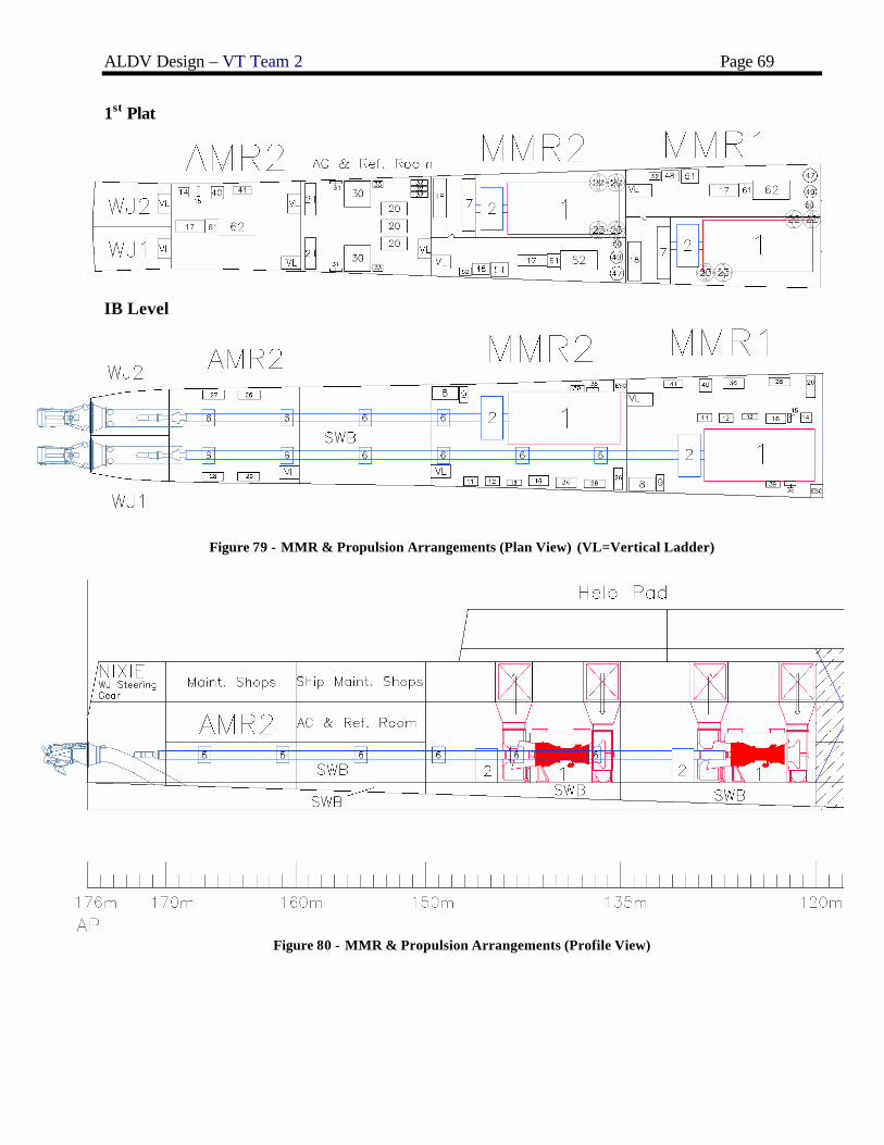
ALDV Design – VT Team 2 Page 69
1st Plat
IB Level
Figure 79 - MMR & Propulsion Arrangements (Plan View) (VL=Vertical Ladder)
Figure 80 - MMR & Propulsion Arrangements (Profile View)

ALDV Design – VT Team 2 Page 70
Table 48 - Machinery Equipment List (MMR1/2, AMR2, Propulsion, AC & Ref. Room) Item No. QTY Equipment Nomenclature Capacity Rating Location
1 2 Gas Turbine, Main 36 mW @ 3600 RPM MMR1/2 2 1 Reduction Gear, stbd MMR1 3 1 Reduction Gear, port MMR2 5 2 Line Shaft 614mm line shaft various 6 2 Bearing, Line Shaft various 7 2 Console, Main Control MMR1/2 8 2 Strainer, Seawater MMR1/2 9 2 Pump, Main SW Circ 230 m3/hr @ 2 bar MMR1/2
10 1 Pump, Stbd rd gear lube oil service 200 m3/hr @ 5 bar MMR1 11 1 Pump, Pt rd gear lube oil service 154 m3/hr @ 5 bar MMR2 12 2 Strainer, Rd gear lube oil 200 m3/hr MMR1/2 13 2 Cooler, Rd gear lube oil MMR1/2 14 2 Purifier, Lube oil 1.1 m3/hr MMR1&AMR2 15 2 Pump, Lube oil transfer 4 m3/hr @ 5 bar MMR1&AMR2 16 2 Assembly, MGT lube oil storage & conditioning MMR1/2 17 4 SS Generator 3430 bkW @ 14300 RPM MMR1/2&AMR1/2 18 1 Switchboard, Ship Service MMR1/2 20 4 Air Conditioning Plants 150 ton 3 RefrigRm&AMR1 21 2 Refrigeration Plants, Ship service 4.3 ton RefrigRm 22 4 Main machinery space fan, Intake 94762 m3/hr MMR1/2 23 4 Main machinery space fan, Exhaust 91644 m3/hr MMR1/2 26 3 Pump, Fire 454 m3/hr @ 9 bar MMR1/2&AMR2 27 1 Pump, Fire/Ballast 454 m3/hr @ 9 bar MMR1/2&AMR2 28 3 Pump, Bilge 227 m3/hr @ 3.8 bar MMR1/2&AMR2 29 1 Pump, Bilge/Ballast 227 m3/hr @ 3.8 bar AMR2 30 2 Distiller, Fresh Water 76 m3/day (3.2 m3/hr) RefrigRm 31 2 Brominator 1.5 m3/hr RefrigRm 32 4 Pump, Chilled water 128 m3/hr @ 4.1 bar RefrigRm&AMR1 33 2 Pump, Potable water 22.7 m3/hr @ 4.8 bar RefrigRm 35 2 Pump, MGT fuel booster 15.9 m3/hr MMR1/2 36 2 Filter separator, MGT fuel 30 m3/hr MMR1/2 39 2 Pre-Filter, MGT fuel service 30 m3/hr MMR1/2 40 2 Purifier, Fuel oil 7.0 m3/hr MMR1&AMR2 41 2 Pump, Fuel transfer 45.4 m3/hr @ 5.2 bar MMR1&AMR2 47 2 Receiver, Starting air 2.3 m3 MMR1/2 48 2 Compressor, Starting air 80 m3/hr @ 30 bar MMR1/2 49 1 Receiver, Ship service air 1.7 m3 MMR1/2 50 1 Receiver, Control air 1 m3 MMR1/2 51 2 Compressor, Air, LP ship service 8.6 bar @194 SCFM MMR1/2 52 2 Dryer, Air 250 SCFM MMR1/2 61 4 SS Reduction Gear MMR1/2&AMR1/2 62 4 SS Engine Enclosure Module MMR1/2&AMR1/2

ALDV Design – VT Team 2 Page 71
Figure 81 - AMR1, JP-5 Pump room, and Sewage Arrangements (VL=Vertical Ladder)
Figure 81 shows the AMR1, JP-5 pump room, and sewage room machinery arrangements. AMR1 is significantly smaller than AMR2 and houses a ship service generator, reduction gear, and engine enclosure module. There is also an emergency switchboard and an AC plant located in AMR1. The JP-5 pump rooms are located port and starboard adjacent to side hull JP-5 fuel tanks. Table 49 lists all equipment located in these four spaces.
Table 49 - Machinery Equipment List – AMR2, JP-5 Pump Room, Sewage Room Item No. QTY Equipment Nomenclature Capacity Rating Location 17 4 SS Generator 3430 bkW @ 14300 RPM MMR1/2&AMR1/2 19 1 Switchboard, Emergency AMR1 20 4 Air Conditioning Plants 150 ton 3 RefrigRm&AMR1 32 4 Pump, Chilled water 128 m3/hr @ 4.1 bar RefrigRm&AMR1 42 2 Pump, JP-5 transfer 11.5 m3/hr @4.1 bar JP-5 Pump Room 43 2 Pump, JP-5 service 22.7 m3/hr @ 7.6 bar JP-5 Pump Room 44 2 Pump, JP-5 stripping 5.7 m3/hr @ 3.4 bar JP-5 Pump Room 45 2 Filter separator, JP-5 transfer 17 m3/hr JP-5 Pump Room 46 2 Filter separator, JP-5 service 22.7 m3/hr JP-5 Pump Room 55 1 Unit, Sewage Collection 28 m3 Sewage Rm 57 2 Pump, Oily waste transfer 12.3 m3/hr @ 7.6 bar Sewage Rm 58 2 Separator, Oil/Water 2.7 m3/hr Sewage Rm 59 1 Sewage Plant 45 people Sewage Rm 61 4 SS Reduction Gear MMR1/2&AMR1/2 62 4 SS Engine Enclosure Module MMR1/2&AMR1/2

ALDV Design – VT Team 2 Page 72
4.7.3 Internal Arrangements
ALDV-16 is internally arranged using four major space classification categories: Mission Support, Human Support, Ship Support, and Ship Machinery Systems. Detailed area and volume summaries for these categories are presented in the ALDV-16 SSCS spreadsheet, Appendix F. Area and volume estimates were originally taken from the ship synthesis model and modified during Concept Development Arrangements.
Mission Support includes ALDS mission operations as well as combat systems, communications, and aviation control. The main deck, crossdeck, and deck house levels are shown in Figure 82. The ALDS Assembly Room/Mission Bay is located above the crossdeck. The ALDS Assembly Room is set up like an assembly line, beginning with two cargo elevators that retrieve cargo from the stores below and ending with a customized elevator that delivers assembled ALDS gliders to the LIM launch tube. The glider assembly process is discussed in further detail in Section 3.3.5. The mission bay also houses the CO state room, an ALDS glider control room, maintenance shops, and one 7m RHIB. Most of the communication systems are located within the deck house, including the pilot house, radio room, and chart room. However, the Combat Information Center (CIC) is located on the DC Deck. A CIWS magazine is located directly under the CIWS within the upper level of the deck house. The deck house also houses a flight control and aviation office with direct view of the helo pad to enhance communications with V-22s and LAMPS during landing and take-off.
Human Support consists of living and commissary spaces, medical and dental, and general ship services. The living and commissary spaces are detailed in Section 4.7.4. The medical and dental room is located forward of amidships on the DC Deck close to berthing quarters. General ship services such as the ship store, laundry, and mail slot are also located on the DC Deck. The DC Deck is shown in Figure 83 on the following page.
Ship Support includes the daily operations of the ship such as ship administration, ship control, damage control, deck auxiliaries, maintenance, stowage, and tankage. Ship administration is comprised of general ship, executive, engineering, supply, deck, and operations departmental offices. Offices are located forward of amidships on the DC Deck just aft of the CIC and CPO berthing. ALDS administration offices include an ALDS glider assembly office, cargo operations office, and LIM operations office. ALDS administration offices are located in the mission bay above the crossdeck. Two waterjet steering gear rooms located on the DC Deck above the waterjets are used for ship control. Damage control includes a DC Central room, three DC repair stations, and two fire fighting stations. DC repair stations are dispersed along the DC Deck, and there is one fire fighting station above each MMR on the DC Deck for survivability. Deck auxiliaries include the anchor handling and windlass room located at the bow of the DC Deck. Various shops are used for ship maintenance, and they are located primarily on the DC Deck aft of amidships. Exceptions include the deck department, ordinance, and ALDS shops located in the mission bay. Ship support stowage is located on the 2nd platform aft of AMR1. ALDV-16 tankage is primarily located below the 2nd platform in order to utilize the unarrangeable space surrounding the LIM launch tube where there is significant hull curvature. The side hulls are also used for DFM and JP-5 tankage. Saltwater ballast is placed at extreme fore and aft locations to maximize trim correction capabilities. Table 47 shows required versus available tankage volume for ALDV-16, and Table 50 lists individual tanks and their respective volumes.
Ship Support also includes ship accessibility, including ship passageways and machinery room escape trunks. All major passageways (Figure 83) are two meters wide and located predominantly on the DC Deck, allowing easy access into and out of compartments. All main passageways have watertight doors at each watertight bulkhead. Below the DC Deck, there is only vertical access to compartments through the use of ladders with watertight hatches. There are two escape trunks in each MMR.
Ship Machinery Systems include all machinery spaces and associated intake and exhaust ducts. Machinery rooms are located on the 2nd platform, the lowest deck of the ship, and sized according to required mechanical and electrical systems. Each MMR contains one waterjet propulsion engine and one ship service generator, and each AMR contains one ship service generator. Ship service generators and fire pumps are separated for survivability. Other main machinery components are detailed in Section 4.7.2. Figure 80 shows the side intake and exhaust arrangement for each MT30. Side intake and exhaust minimizes lost area in the mission bay and reduces RCS. Both intakes are located on the port side, and both exhausts are located on the starboard side to avoid inhaling exhaust. Intakes and exhausts are located as high as possible at the DC Deck level, but they still may be subjected to spray from the center and side hulls. As a result, louvered panels with plenum are used to combat water entry.
A complete set of detailed arrangement drawings are included with this report.

ALDV Design – VT Team 2 Page 73
Figure 82 - Main Deck, Crossdeck, Deck house
Figure 83 - Damage Control Deck
Figure 84 - Plan View: 1st Platform

ALDV Design – VT Team 2 Page 74
Figure 85 - Plan Views: 2nd Platform and BL
Table 50 – Tank Capacity Plan (Frame = 2.5m) Tank Capacity (m3) Tank Capacity (m3)
2-32-5-F (DFM) 51 4-22-2-W (FW) 87 2-32-6-F (DFM) 51 4-22-1-W (FW) 87 2-36-5-F (DFM) 64 4-60-1-W (SW) 193 2-36-6-F (DFM) 64 4-60-2-W (SW) 193 2-40-5-F (DFM) 64 5-12-1-W (SW) 83 2-40-6-F (DFM) 64 5-12-2-W (SW) 83 4-32-5-F (DFM) 42 5-17-3-W (SW) 2.5 4-32-6-F (DFM) 42 5-17-4-W (SW) 2.5 4-36-5-F (DFM) 66 5-18-3-W (SW) 19 4-36-6-F (DFM) 66 5-2-2-W (SW) 34 4-40-5-F (DFM) 77 5-24-3-W (SW) 23 4-40-6-F (DFM) 77 5-24-4-W (SW) 23 2-44-5-J (JP-5) 125 5-30-3-W (SW) 25 2-44-6-J (JP-5) 125 5-30-4-W (SW) 25 2-48-5-J (JP-5) 123 5-48-1-W (SW) 107 2-48-6-J (JP-5) 123 5-48-2-W (SW) 107 4-44-5-J (JP-5) 132 5-54-1-W (SW) 109 4-44-6-J (JP-5) 132 5-54-2-W (SW) 109 4-48-5-J (JP-5) 104 5-60-1-W (SW) 73 4-48-6-J (JP-5) 104 5-60-2-W (SW) 73 5-2-1-Q (LO) 26 5-6-1-W (SW) 87 5-42-4-Q (LO) 21 5-6-2-W (SW) 87 5-36-3-W (FW) 21 5-B-1-W (SW) 25 5-36-4-W (FW) 21 5-B-2-W (SW) 25
ALDV-16 is divided into three Collective Protection System (CPS) zones as shown in Figure 86 below. CPS
zones are designed to protect vital ship functions and spaces from airborne chemical or biological attacks. CPS zone 1 contains the entire mission bay, with airlocks located at the fore and aft external accesses leading to the main deck. CPS zone 2 contains the CIC, CPO berthing, crew berthing, ALDS cargo and ammunition, and other vital spaces on

ALDV Design – VT Team 2 Page 75
the DC deck. This CPS zone has an airlock at the 45 meter bulkhead on the DC deck. CPS zone 3 contains the two main machinery rooms, ALDS cargo and ammunition, galleys, and mess rooms, with an airlock at the 150 meter bulkhead on the DC deck.
Figure 86 - CPS Zones – Profile View
4.7.4 Living Arrangements
Living space requirements were initially estimated based on the crew size from the ship synthesis model and refined using the manning estimate in Section 4.6. The model calculates areas for officer and enlisted living, mess rooms, and human support facilities. ALDV-16 final accommodation areas were increased from original estimates due to additional arrangeable area made available by locating the LIM launch tube in the inner bottom. Larger accommodation areas suggest that additional accommodations could be added in future design spiral iterations. However, it is likely that the increased area will be essential to a highly trained and versatile crew or MSC crew necessary for the operation of ALDV-16. Table 51 lists the accommodation space for the crew.
Table 51 - Accommodation Space
ITEM Accommodation
Quantity Per
Space No.
Spaces Area Each
Tot. Area
m2 m2 CO 1 1 1 15 15 XO 1 1 1 10 10 Department Head 4 1 4 8 32 Other Officers 0 2 0 8 0 CPO 15 6 2.5 15 37.5 Enlisted 24 12 2 15 30 Officer Sanitary 6 6 1 30 30 CPO Sanitary 15 6 2.5 25 62.5 Enlisted Sanitary 24 12 2 20 40 TOTAL 45 16 257
Living space is located around amidships within close proximity to mess rooms, galleys, and other human
support spaces. Living spaces are arranged with daily traffic flow and ship survivability in mind. The CO has the largest berthing space on the ship, followed by the XO, each with their own state room and bath. XO and CO berthing spaces are located in the deck house, allowing easy access to ship communication systems. Department heads have their own state rooms but share one bath. Department head berthing is located at the fore end of the DC Deck. CPO berthing is located just aft of department head berthing on the DC Deck. There are three CPO berthing rooms with rooms holding four, five, and six CPOs, and three separate CPO sanitary spaces. CPO berthing is subdivided to accommodate both males and females. Enlisted berthing is located on the 1st platform. Enlisted berthing is arranged into three separate rooms: two rooms of nine crew members and one room of six crew members. Enlisted berthing also is separated to accommodate males and females. Crew berthing also includes ample space for crew recreation. Figure 87 shows a detailed view of the ALDV-16 crew berthing space.
Lounge and mess rooms are located aft of amidships on the DC Deck. The CPO mess and lounge is located on the starboard side of the ship and includes a serving bar and two tables. The Wardroom mess and lounge is located across the passageway from the CPO mess and lounge, and is connected to the Wardroom galley. The Wardroom mess and lounge includes a table, serving bar, and television. The crew galley and crew mess are just aft of the CPO

ALDV Design – VT Team 2 Page 76
and Wardroom mess and lounges. The crew mess consists of a serving bar, salad bar, and two large tables for enlisted crew members. Figure 87 also shows a detailed view of mess rooms, lounges, and galleys.
Figure 87 - Officer and Crew Mess Rooms and Galley, Crew Berthing
4.7.5 External Arrangements
Minimizing Radar Cross Section (RCS) plays a major role in external arrangements. All sides of the hull above the waterline as well as the deck house structure are angled in at ten degrees. An Advanced Enclosed Mast/Sensor (AEM/S) is placed on top of the deck house for maximum functionality, and is also designed with a ten degree slope.
To enhance the self defense capabilities of ALDV-16, the AAW System alternative was upgraded to alternative two by the ALDV program manager. This alternative includes a CIWS, which was placed on top of the deck house for maximum coverage. Figure 88 shows the combat systems coverage zone of ALDV-16.
The forward end of the LIM launch tube is surrounded by a protective combing that is designed to prevent water entry during ALDS launch. The tube opening is also fixed with a removable hatch controlled by actuators to prevent water entry during cruise.
Anchor handling and mooring are located at the forward end of the DC deck. The anchor stowage and chain locker are located just below, extending from the keel to the 1st platform. There is also a 7m RHIB stored and deployed from the port side of the mission bay.

ALDV Design – VT Team 2 Page 77
Figure 88 - Combat Systems Coverage Zones (Profile and Plan View)
4.8 Weights and Loading
4.8.1 Weights
Ship weights are grouped by SWBS. The majority of the weights are obtained from manufacturer information. ASSET parametrics and the ship synthesis model were used when this information was unavailable. The VCGs and LCGs of the weights are determined from general ship and machinery arrangements. These values are utilized to calculate moments and the lightship center of gravity. A summary of lightship weights and centers of gravity by SWBS group is listed in Table 52. The complete weights spreadsheet is provided in Appendix E.
Table 52 - Lightship Weight Summary SWBS Group Weight (MT) VCG (m-Abv BL) LCG (m-Aft FP)
100 1626 7.56 97.85 200 449 5.25 149.12 300 228 6.27 97.91 400 133 10.03 71.92 500 448 4.91 66.51 600 149 7.58 79.68 700 34 2.89 88.00
Margin (1.7%) 52 6.7 96.9 Total (LS) 3119 6.7 96.9

ALDV Design – VT Team 2 Page 78
4.8.2 Loading Conditions
There are two loading conditions, as defined in DDS 079-1, to be considered for ALDV-16: Full Load and Minimum Operating (Minop). The lightship weights and centers of gravity are used in both loading conditions along with the loads weights and centers in order to determine the centers of gravity for each condition. In the Full Load condition, ALDS cargo, general stores, and provisions are at full capacity, while all fuel oil and potable water tanks are filled to 98% capacity. In the Minimum Operating condition, ALDS cargo, fuel, and general stores are filled to 33% capacity, while all potable water tanks are filled to 66% capacity. Ballast tanks are near full capacity in the Minop condition. A summary of the weights for the Full Load condition is provided in Table 53. A summary for the Minimum Operating condition is provided in Table 54.
4.9 Hydrostatics and Stability
HECSALV was utilized to assess the hydrostatics, intact stability, and damage stability of ALDV-16. The ship offsets are imported from FASTSHIP and hydrostatics are calculated for a range of drafts. The curves of form, coefficients of form, and cross curves are calculated using this information. Intact stability is calculated in the two loading conditions using this data. Once the load conditions are defined and balanced, intact stability and damage stability are analyzed.
Table 53 - Weight Summary: Full Load Condition Item Weight (MT) VCG(m-BL) LCG(m-FP)
Lightship w/ Margin 3119 6.7 97.0 Ships Force 5.5 8.35 65.00
ALDS/Weapons Loads 900.0 8.35 89.95 Provisions 3.3 5.97 70.00
General Stores 1.2 6.75 70.00 Diesel Fuel Marine 558.9 7.80 96.24
JP-5 706.0 7.85 119.79 Lubricating Oil 43.0 1.37 55.58
SW Ballast 0 1.29 84.95 Fresh Water 129 3.02 70.186
Total 5465
7.1 97.7
Table 54 - Weight Summary: Minop Condition Item Weight (MT) VCG (m-BL) LCG (m-FP)
Lightship w/ Margin 3119 6.7 97.0 Ships Force 5.5 8.35 65.00
ALDS/Weapons Loads 300.0 7.80 89.95 Provisions 1.1 5.97 70.00
General Stores 0.4 6.75 70.00 Diesel Fuel Marine 186.3 5.28 93.25
JP-5 235.3 5.14 116.54 Lubricating Oil 14.3 0.81 55.55
SW Ballast 1518 1.65 99.67 Fresh Water 85.9 2.61 70.19
Total 5466 5.14 96.6
4.9.1 Intact Stability
In each condition, trim, stability, and righting arm data are calculated. All conditions are assessed using DDS 079-1 stability standards for beam winds with rolling. Two criteria must be met to achieve satisfactory intact stability: (1) the heeling arm at the intersection of the righting arm and heeling arm curves must not be greater than six-tenths of the maximum righting arm; (2) the area under the righting arm curve and above the heeling arm curve (A1) must not be less than 1.4 times the area under the heeling arm curve and above the righting arm curve (A2).

ALDV Design – VT Team 2 Page 79
After an initial analysis, additional buoyancy was added to the stern of the ship by reducing the cut-up and the bow was made more fine by reducing the parallel midbody forward. This was done to move the LCB aft and correct significant trim by the stern in the lightship condition. I t was accomplished with only a small increase in displacement and increase in structural weight at the same design waterline. The changes were only made in HECSALV. This hullform modification will be made to other models (FASTSHIP, MAESTRO, etc.) next time around the design spiral. An alternative to this hullform modification is moving the deck house and side hulls forward. Another option is to rearrange machinery spaces and reconfigure tankage, moving weight forward. The Minop trim and stability summary are shown in Table 55 and the Full Load trim and stability summary are shown in Table 56. Table 57 displays the righting arm and heeling arm data for the Minop condition, while Table 58 contains the righting arm and heeling arm data for the Full Load condition.
Table 55 - Minop Trim and Stability Summary Weight VCG LCG TCG FSMom Item MT m m-FP m-CL m-MT Light Ship 3119 6.700 97.000A 0.000 ---- Lube Oil 14 0.811 55.551A 0.966P 4 Fresh Water 86 2.613 70.189A 1.520P 70 SW Ballast 1518 1.649 99.670A 0.135S 235 Fuel (JP-5) 235 5.142 116.541A 0.000S 6 Fuel (DFM) 186 5.276 93.254A 0.000S 9 Dry Cargo 300 7.8 89.952A 0.000P 1113 Misc. Weights 7 10.684 68.000A 0.000 0
Displacement 5466 5.142 96.620A 0.001S 1435 Stability Calculation Trim Calculation KMt 10.537 m LCF Draft 4.8 m VCG 5.142 m LCB 96.604A m-FP GMt (Solid) 5.395 m LCF 98.269A m-FP FSc 0.254 m MT1cm 206 m-MT/cm GMt (Corrected) 5.649 m Trim 0.004 m-A
List 0.0S Deg
Table 56 - Full Load Trim and Stability Summary Weight VCG LCG TCG FSMom Item MT m m-FP m-CL m-MT Light Ship 3119 6.700 95.490A 0.000 ---- Lube Oil 43 1.368 55.575A 0.977P 0 Fresh Water 129 3.021 70.189A 1.580P 0 SW Ballast 0 0.000 0.000 0.000 0 Fuel (JP5) 706 7.850 119.785A 0.000S 0 Fuel (DFM) 559 7.800 96.235A 0.000S 0 Dry Cargo 900 8.35 83.986A 0.000P 0 Misc. Weights 10 10.684 70.000A 0.000 0
Displacement 5465 7.073 97.663A 0.000S 0 Stability Calculation Trim Calculation KMt 10.538 m LCF Draft 4.8 m VCG 7.073 m LCB 96.645A m-FP GMt (Solid) 3.465 m LCF 98.608A m-FP FSc 0.000 m MT1cm 206 m-MT/cm GMt (Corrected) 3.465 m Trim 0.270 m-A List 0.0S deg

ALDV Design – VT Team 2 Page 80
Figure 89 - Righting Arm (GZ) and Heeling Arm Curve for Minop Condition
Table 57 - Righting Arm (GZ) and Heeling Ar m Data for Minop Condition Beam Wind with Rolling Stability Evaluation (per US Navy DDS079-1)
Displacement 5466 MT Angle at Maximum GZ 45.1 deg GMt (corrected) 5.649 m Wind Heeling Arm Lw 0.366 m Mean Draft 4.780 m Angle at Intercept 45.1 deg Projected Sail Area 1600 m^2 Wind Heel Angle 4.5 deg Vertical Arm 9.75 m-BL Maximum GZ 2.084 m Wind Pressure Factor 0.0035 Righting Area A1 1.20 m-rad Wind Pressure 0.02 bar Capsizing Area A2 0.37 m-rad Wind Velocity 100 knts Heeling Arm at 0 deg 0.368 deg Roll Back Angle 25.0 deg
Figure 90 - Righting Arm (GZ) and Heeling Arm Curve for Full Load Condition

ALDV Design – VT Team 2 Page 81
Table 58 - Righting Arm (GZ) and Heeling Arm Data for Full Load Condition Beam Wind with Rolling Stability Evaluation (per US Navy DDS079-1)
Displacement 5465 MT Angle at Maximum GZ 41.5 deg GMt (corrected) 3.465 m Wind Heeling Arm Lw 0.313 m Mean Draft 4.79 m Angle at Intercept 41.5 deg Projected Sail Area 1600 m^2 Wind Heel Angle 5.5 deg Vertical Arm 9.75 m-BL Maximum GZ 1.246 m Wind Pressure Factor 0.0035 Righting Area A1 0.67 m-rad Wind Pressure 0.02 bar Capsizing Area A2 0.27 m-rad Wind Velocity 100 knts Heeling Arm at 0 deg 0.315 deg Roll Back Angle 25.0 deg
The calculated trim and heel are acceptable for the ship’s stability criteria for both loading conditions. Both conditions for beam winds with rolling defined by DDS 079-1 are also satisfied. Therefore, ALDV-16 is satisfactory in both loading conditions for intact stability.
4.9.2 Damage Stability
Transverse bulkheads are located to insure floodable length requirements are met. The Full Load and Minimum Operating conditions are then analyzed for damage stability using both a 15% and 50% LWL damage length in accordance with DDS 079-01 for large multi-hulls . The 15% damage length, 26 meters for ALDV-16, is applied along the length of the center hull from bow to stern. Worst case penetration to 20% of the local beam is used. The vertical height of the damage extends from the keel to the DC Deck. The side hulls are analyzed using a 50% damage length, corresponding to 27 meters for ALDV-16. The 50% LWL relates to the length of the side hulls, not the center hull. Only one side hull is damaged during the side hull damage analysis; the center hull remains intact. There are a total of 30 damage cases , 15 for each loading condition. In each case, the heel of the ship must remain less than 15 degrees, and the margin line (0.5 meters below the deck edge) must not be submerged. The remaining dynamic stability must also be adequate (A1 > 1.4A2).
Table 59 - Minop Damage Worse Damage Cases Intact Damage BH 5-45
(trim) Damage BH 100-132.5
(heel) Draft AP (m) 4.804 3.406 4.732 Draft FP (m) 4.800 9.314 4.698 Trim on LBP (m) 0.004 A 5.908 F 0.034 A Total Weight (MT) 5466 7636 5319 Static Heel (deg) 0.0 S 1.0 S 3.9 P GMt (upright) (m) 5.649 5.612 3.344 Maximum GZ 2.735 1.876 Maximum GZ angle 48.4 S 49.6 P GZ Pos. Range (deg) 1 – 60 3.9 – 60
Figure 91 - Limiting Trim Case at Minop

ALDV Design – VT Team 2 Page 82
Figure 92 - Limiting Heel Case for Minop Condition
Table 60 - Full Load Damage Results Intact Damage BH 5-45
(trim limit) Damage BH 80-110
(heel limit)
Draft AP (m) 4.787 3.074 4.395 Draft FP (m) 4.781 9.890 4.657 Trim on LBP (m) 0.027 A 6.816 F 0.263 F Total Weight (MT) 5465 7851 5196 Static Heel (deg) 0.0 S 1.5 S 11.9 P GMt (upright) (m) 3.465 3.937 1.968 Maximum GZ 1.76 0.772 Maximum GZ Angle
(deg) 43 S 46 P
GZ Pos. Range (deg) 1 – 60 12 – 60
Figure 93 - Limiting Trim Case for Full Load Condition

ALDV Design – VT Team 2 Page 83
Figure 94 - Limiting Heel Case for Full Load
The limiting trim case in the Minop loading condition is for damage between bulkheads one (5 meters aft of FP) and four (45 meters aft of FP), with the LIM launch tube flooded as well. The limiting heel case is for flooding in the side hulls between bulkheads located 100 meters and 132.5 meters aft of the FP. Results can be found in Table 59. The trim case is shown in Figure 91, displaying the damaged compartments in red. Figure 92 shows the results of the limiting heel case along with the righting arm curve. ALDV-16 damaged stability is adequate in the Minop loading condition, although flooding the LIM launch tube causes severe trim.
The limiting trim case in the Full Load condition is for damage between bulkheads one (5 meters aft of FP) and four (45 meters aft of FP), with the LIM launch tube flooded as well. The limiting heel case is for flooding in the side hulls between bulkhead located 80 meters and 110 meters aft of the FP. Results can be found in Table 60. The trim case is shown in Figure 93, displaying the damaged compartments in red. Figure 94 shows the results of the limiting heel case along with the righting arm curve. ALDV-16 damaged stability is adequate in the Full Load condition, although flooding the LIM launch tube again causes severe trim.
4.10 Seakeeping
A seakeeping analysis for ALDV-16 in the full load condition was performed using the SWAN 2 computer program. SWAN 2 simulates waves and water flow around models of high speed vessels by using a three-dimensional Rankine panel method. This method was chosen over strip theory and extended strip theory because neither is applicable to multi-hull vessels. The purpose of the analysis was to predict if ALDV-16 could meet US Navy Motion Limit Criteria and ORD thresholds. Table 61 compares this criteria to the SWAN 2 results.
The hullform was modeled using offsets from HECSALV. Ship responses were calculated for regular waves in Sea States 3, 4, 5, 6, 7, and 8 (average significant wave heights of 0.88, 1.88, 3.25, 5.00, 7.50, and 11.50 meters respectively) for forward speeds of 5, 10, 20, 30, and 40 knots at four or more heading angles. Roll, pitch, and yaw motions were analyzed about the center of gravity, and accelerations were analyzed on the bridge and within the ALDS Assembly Room. A summary of analysis locations can be seen in Table 62. Outputs included accelerations and ship motions, and this data was plotted on a Speed – Polar plot using TECPLOT 10. The operating envelope established by the criteria in Table 61 was also plotted, and the bold red line indicates these limits.

ALDV Design – VT Team 2 Page 84
Table 61 - Limiting Motion (Significant Amplitude) and Analysis Results
Application Roll Pitch Yaw Longitudinal Acceleration
Transverse Acceleration
Vertical Acceleration
ORD Threshold Sea State
Sea State Achieved
Bridge Personnel 8° 3° - 0.2g 0.2g 0.4g 7
Sea State 3 Restricted
ALDS Assembly 6° 3° - - - - 5
Sea State 3 Restricted
Table 62 - Seakeeping Analysis Locations
As Table 61 shows, ALDV-16 does not currently meet threshold sea states. Notable failures occur across the board in following seas (300° - 60°); only at very high sea states does ALDV-16 fail in head (120° – 240° ) or beam (60° – 120° and 240° – 300°) seas. Figure 95 shows that by Sea State 3, ALDV-16 is already restricted by rolling criteria for bridge personnel to operation in only beam and head seas.
Figure 95 - Speed - Polar Plot of ALDV Rolling Motions in Sea State 3, Limited by Bridge Personnel Roll Criteria
The ALDS onboard glider assembly process has more stringent roll criteria. As Figure 96 shows, by Sea State 3 ALDV-16 is more restricted by the ALDS mission than by bridge personnel criteria, and it is only able to operate between heading angles of 66°and 297°.
Application X location from amidships, m
Y location from CL, m
Z location from DWL, m
Bridge Personnel
20.7 0 11.6
ALDS Assembly -18.3 0 6.6

ALDV Design – VT Team 2 Page 85
Figure 96 - Speed – Polar Plot of ALDV Rolling Motions in Sea State 3, Limited by ALDS Assembly Rolling Criteria
ALDV-16 is also limited by pitch in Sea State 3, with both ALDS assembly criteria and bridge personnel criteria carrying a pitch limit of 3°. ALDV-16 is not restricted by pitch as severely as it is by roll, but as Figure 97 shows, it is still only able to operate at 20 knots between approximately 75° and 354°, and at 40 knots between approximately 78° and 348°. Curiously, the SWAN 2 analysis suggests that at a speed of 30 knots, the vessel operates within pitch criteria.
Figure 97 - Speed - Polar Plot of ALDV Pitch Motions in Sea State 3, Limited by both ALDS and Bridge Personnel Motion Criteria
ALDV-16 meets acceleration criteria as specified for bridge personnel better according to this analysis. Figure 98 shows failure due to a heavy transverse acceleration imposed at 30 knots by following seas off the port side at

ALDV Design – VT Team 2 Page 86
Sea State 3. The first time that all three accelerations (transverse, longitudinal, and vertical) fail is in Sea State 6, as Figure 99, Figure 100, and Figure 101 show.
Figure 98 - Speed - Polar Plot of ALDV Transverse Accelerations in Sea State 3, Limited by Bridge Personnel Acceleration Criteria
Figure 99 - Speed - Polar Plot of ALDV Longitudinal Accelerations in Sea State 6, Limited by Bridge Personnel Acceleration Criteria

ALDV Design – VT Team 2 Page 87
Figure 100 - Speed - Polar Plot of ALDV Transverse Accelerations in Sea State 6, Limited by Bridge Personnel Acceleration Criteria
Figure 101 - Speed - Polar Plot of ALDV Vertical Accelerations in Sea State 6, Limited by Bridge Personnel Acceleration Criteria
Data obtained using this analysis implies a failure to meet seakeeping criteria. The long length of the center hull causes high pitch moments and accelerations. The high GM T causes high roll accelerations. Roll accelerations could

ALDV Design – VT Team 2 Page 88
be reduced by reducing hull spacing, but this will also reduce arrangeable area and possibly increase resistance. Seakeeping issues will be investigated in greater detail next time around the design spiral. Once the current problems are identified and solved, a seakeeping analysis will also be performed for the helo pad and the highest peak of the LIM launch tube to asses ALDS launch feasibility.
4.11 Cost and Risk Analysis
Table 63 – Final Concept Cost Comparison
ENGINEERING INPUT Concept Baseline
Final Concept Design
Hull Structure Material (select one) Steel 1 1 Aluminum 0 0 Composite 0 0 Deck house Material (select one) Steel 1 1 Aluminum 0 0 Composite 0 0 Hull Form (select one) Monohull 0 0 Catamaran 0 0 Trimaran 1 1 Plant Type (select one) Gas Turbine 1 1 Diesel 0 0 Diesel Electric 0 0 CODOG 0 0 CODAG 0 0 Plant Power Power Rating (in BHP) 72,000 kw 72,000 kw Main Propulsion Type (select one) Fixed Pitch Propeller 0 0 Controllable Reversible Propeller 0 0 Waterjet 1 1 Weights (MT) 100 (less deck house) 1363 1476 150 (deck house) 125 150 200 (less propeller) 268 268 245 (propeller) 181 181 300 (electrical) 240 228 400 (command and surveillance) 153 134 500 (auxiliary) 544 448 600 (outfit) 200 149 700 (armament) 6 34 Margin 155 52 Lightship (MT) 3235 3119 Full Load Displacement (MT) 5350 5465 Operating and Support Complement 45 45 Steaming Hrs Underway/Yr 3000 3000 Fuel Usage (BBL/Yr) 50000 50000 Service Life (Yrs) 30 30
Cost Element Concept Baseline
Final Concept Baseline
Shipbuilder 328.98 347.00 Government Furnished Equipment (a) 123.60 138.94 Other Costs 15.23 16.10 Follow Ship Acquisition Cost 467.81 502.04 Operating and Support Personnel (Direct & Indirect) 78.41 78.41 Unit Level Consumption (Fuel, Supplies, Stores, etc.) 53.56 54.84 Life Cycle Cost (less non-recurring) 599.78 635.29

ALDV Design – VT Team 2 Page 89
4.11.1 Cost and Producibility
Cost calculations for ALDV-16 were based on complexity-adjusted, weight-based regression equations. A comparison of costs is displayed in Table 63. Concept Development changes resulted in a higher follow-ship acquisition cost ($502M) than specified in the ORD ($470M). This is due to increased structural weight and the addition of CIWS. This overrun will be addressed next time around the design spiral. Although acquisition cost exceeds the threshold value specified in the ORD, it is less than original ADM requirements ($650M).
Despite the apparent comple xity of ALDV-16, it is a relatively producible design. The ALDV-16 design features a hard chine on the center hull just above the waterline, allowing the center hull above the waterline to be built with flat or single curvature plating. The liberal use of flat plating in design of the crossdeck structure, deck house, pilot house, transom, and hulls also helps to make the design more producible. The cost of outfitting and installation is reduced by larger deck heights and the use of CPS zones and zonal distribution systems for electric power and firemain systems. Structural material variability was also kept to a minimum.
4.11.2 Risk
Based on the ALDV OMOR, ALDV-16 is a relatively low risk ship. The low risk of this design is due to low levels of automation and a mechanical drive propulsion system. The risk associated with ALDV-16 is related to its trimaran hullform, wave piercing tumblehome hullform, automated systems associated with ALDS operations, and LIM independent energy stores. All risk alternatives are described in detail in Table 36. To further reduce ALDV risk, additional technology development and testing is necessary.

ALDV Design – VT Team 2 Page 90
5 Conclusions and Future Work
5.1 Final Concept Design
Table 64 – Final Concept Design with Comparison to Baseline Characteristic Concept Baseline Final Concept Design
Hullform Trimaran Trimaran
∆ (MT) 5350 5465
LWL (m) 176 176
Beam (m) 28.3 28.3
Draft (m) 4.78 4.78
D10 (m) 15.4 15.4
Displacement to Length Ratio, C∆L (lton/ft) 9.45 9.65
Beam to Draft Ratio, CBT 5.91 5.91
W1 (MT) 1354 1626
W2 (MT) 449 449
W3 (MT) 228 228
W4 (MT) 133 133
W5 (MT) 448 448
W6 (MT) 149 149
W7 (MT) 6 34
Lightship ∆ (MT) w/margin 2822 (1% weight margin) 3119 (1.7% weight margin)
Loads (MT) 2528 2346
KG (m) 6.00 7.073
GM/B 0.130 0.122
Propulsion System
Mechanical Drive w/ Epicyclic Gears: 2 x 300SII Waterjets 2 x MT30 4 x 3500 KW SSGTG
Mechanical Drive w/ Epicyclic Gears: 2 x 300SII Waterjets 2 x MT30 4 x 3500 KW SSGTG
Engine inlet and exhaust Side Side
MCM system Degaussing Degaussing ASW system AN/SLQ-25 NIXIE AN/SLQ-25 NIXIE
ASUW system Surface Search Radar - AN/SPS-73 DDG51 Small Arms & Pyro Storage 1 x 7M RHIB
Surface Search Radar - AN/SPS-73 DDG51 Small Arms & Pyro Storage 1 x 7M RHIB
AAW system MK XII AIMS IFF Combat DF
MK XII AIMS IFF Combat DF CIWS
LAMPS system LAMPS MKIII Aviation Fuel System SINGLE SH-60 – Mission Fuel
LAMPS MKIII Aviation Fuel System SINGLE SH-60 – Mission Fuel
C4I system DDG51 Navigation System Communication Suite Level A
DDG51 Navigation System Communication Suite Level A
Average Deck Height (m) 2.6 2.6
Total Officers 6 6
Total Enlisted 39 39
Total Manning 45 45
Follow Ship Acquisition Cost $ 467.8 Million $ 502.0 Million
Life Cycle Cost $ 599.8 Million $ 635.3 Million
Displacement increased as a result of hull form changes to shift the LCB aft without changing other principle characteristics. Lightship weight increased as a result of the re-estimate of hull weight and addition of CIWS. Loads decreased due to the removal of baseline excess fuel. Cost increased due to the increase in structural weight and

ALDV Design – VT Team 2 Page 91
addition of CIWS. KG and LCG were re-estimated based on general arrangements. An effort was made to increase the weight margin, but this must be further increased to at least 5% in the next design iteration.
5.2 Assessment
A comparison of final concept design results to ORD requirements is presented in Table 65.
Table 65 - Compliance with Requirements
Technical Performance Measure Original Threshold
Original Goal
Concept BL
ORD TPM (Requirement)
Final Concept BL
ALDS Mission Duration (days) 3 8 4 4 5
Total mission payload weight (core, modules, fuel)
- - 1291 MT 1291 MT 1606 MT
Endurance Range (nm) 2500 3500 6485 3500 4687
Sprint Range (nm) 250 500 1145 500 1477
Stores Duration (days) 20 45 29 29 29
Collective Protection System none full full full full
Minimum Sustained Speed (knots) 40 50 38.5 40 45.6
Maximum Crew Size 60 35 45 45 45
RCS (m3) 300 150 185 185 185
Vulnerability (Hull/Deck house Material)
Steel hull / aluminum deckhouse
Steel Steel Steel Steel
Seakeeping (Sea State)
- launch and recover aircraft 5 5 5 3
- full capability of all systems 7 6 6 3
- survive 9 8 8 5
Average follow-ship acquisition cost ($M)
650.0 400.0 467.8 470.0 502.0
Life cycle cost ($M) - - 599.8 600.0 635.3
Maximum level of risk (OMOR) 0.0 1.0 0.202 0.202 0.202
Overall Measure of Effectiveness (OMOE)
0.0 1.0 0.216 0.216 0.346
ORD requirements not met during the first concept design spiral iteration include seakeeping and cost.
Required sea states were not met during this analysis . The long length of the center hull causes high pitch moments and accelerations. The high GM T causes high roll accelerations. Roll accelerations could be reduced by reducing hull spacing, but this will also reduce arrangeable area and possibly increase resistance. Seakeeping issues will be investigated in greater detail next time around the design spiral. Although acquisition cost exceeds the threshold value specified in the ORD, it does meet ADM requirements. A full additional MEB cargo day was added in concept development (for a total of 5) to balance the ship after hull form changes and improved weight and space estimates. Principle characteristics would be reduced in the next design iteration to reduce cost within the requirement for 4 MEB days. Hull spacing and hullform changes will also be considered to improve seakeeping.
ALDV-16 does incorporate an effective combination of proven technology and new revolutionary technology. It integrates the ALDS system including automated cargo handling technologies, onboard glider assembly, and LIM mechanical launch into a feasible trimaran design. The use of an AEM/S further reduces RCS, and protects the ship’s vital electronic sensors. The use of two MT30 gas turbines provides a sustained speed exceeding the ORD threshold value. Endurance and sprint ranges also exceed goal values, and ALDV-16 exceeds US Navy damage stability requirements. Improvements resulted in an overall measure of effectiveness (OMOE) that is higher than the original concept baseline.
5.3 Future Work
• Reduce follow-ship acquisition cost to $470M. Additional fuel may be removed while still satisfying endurance range requirements. MEB cargo days may be reduced. Both of these will allow principle characteristics to be reduced with reduction in lightship weight and cost.
• Increase weight margin to 5-10%. • Consider details and feasibility of LIM launch and impact on ship.

ALDV Design – VT Team 2 Page 92
• Optimize the longitudinal and transverse locations of the side hulls to reduce resistance and improve seakeeping. Consider reducing length of center hull.
• Consider details and feasibility of MT30’s side intake and exhaust. • Consider using diesel generators (SSDGs) or smaller SSGTGs. • Further reduce scantlings to optimize adequacy parameters and reduce structural weight. • Consider use of composite materials for the mission bay, deck house, and pilot house. • Analyze structural and system vulnerability. • Assess reliability, maintainability, and availability (RMA). • Model flooded compartments in MAESTRO for major damage cases to assess damaged structural integrity.
5.4 Conclusions
The ALDV requirement is based on the ALDV Mission Need Statement (MNS) and Virginia Tech ALDV Acquisition Decision Memorandum (ADM). ALDV will operate in sensitive littoral regions, close-in, depend on passive survivability and stealth, with high endurance and low manning. ALDV must support troops ashore operating from a seabase or shuttle ship using ALDS. ALDS (Advanced Logistics Delivery System) is a ship-launched, over-the-beach, logistics delivery system that uses cargo-filled unmanned gliders and other revolutionary technology. ALD V must provide a platform for this airborne logistics delivery system. This includes employing automated techniques for assembling unmanned ALDS gliders and supporting a mechanical launching system for an air delivery system. ALDV must also provide humanitarian aid using ALDS. ALDV supports ISR, MCM, ASW, ASUW, and AAW self defense systems using networked modular mission packages built around off-board, unmanned systems. It also must support V-22 Ospreys and LAMPS, providing for launch and takeoff, landing, fueling, planning and control.
Concept Exploration trade-off studies and design space exploration are accomplished using a Multi-Objective Genetic Optimization (MOGO) after significant technology research and definition. Objective attributes for this optimization are cost, risk (technology, cost, schedule and performance) and mission effectiveness. The product of this optimization is a series of cost-risk-effectiveness frontiers which are used to select alternative designs and define Operational Requirements (ORD1) based on the customer’s preference for cost, risk and effectiveness. ALDV Option 16 is a low risk, low cost, knee-in-the-curve trimaran design on the cost-risk-effectiveness frontier. This design was chosen because it has a sharp increase in effectiveness with a minimal increase in cost at a low risk level.
ALDV-16 has a wave-piercing bow to decrease wave resistance and improve high speed performance in high sea states. It has a tumblehome hullform and other stealth technology such as an Advanced Enclosed Mast/Sensor (AEM/S) to reduce radar cross section. ALDV-16 has an ALDS Mission Bay located above the crossdeck for automated glider assembly and a unique Linear Induction Motor (LIM) for mechanical launch of aircraft. It uses other automation technology such as watch standing technologies that include GPS, automated route planning, electronic charting and navigation (ECDIS), collision avoidance, and electronic log keeping. ALDV-16 also employs automated cargo handling technologies such as conveyor belts, cargo elevators, robotic pickers, and radio frequency identification (RFID). Concept Development included hullform development and analysis for intact and damage stability, structural finite element analysis, propulsion and power system development and arrangement, general arrangements, machinery arrangements, combat and mission system definition and arrangement, seakeeping analysis, cost and producibility analysis and risk analysis. The final concept design satisfies critical operational requirements in the ORD within constraints with additional work required to improve seakeeping and reduce structural weight and lower cost. The wave piercing tumblehome (WPTH) hullform reduces both wave resistance and RCS. A mechanical drive propulsion system with epicyclic gears provides power to two 300SII Kamewa Waterjets using two MT30 gas turbines and provides electrical power using four SSGTGs. The mission bay provides sufficient space for ALDS onboard glider assembly operations, and the ALDS cargo handling technologies and mechanical launching system are also integrated into the ship design. There is a helo pad with refueling capabilities for V-22 Osprey and LAMPS helicopters. To enhance the AAW self defense capabilities of ALDV-16, a CIWS is placed on top of the deck house for maximum coverage. ALDV-16 is a revolutionary ship design that integrates an airborne logistics delivery system and should be considered as a potential platform for ALDS.

ALDV Design – VT Team 2 Page 93
References
1. Advanced Enclosed Mast/Sensor (AEM/S). 2005. The Federation of American Scientists. <http://www.fas.org/man/dod-101/sys/ship/aems.htm>
2. Brown, Dr. Alan and LCDR Mark Thomas, USN. “Reengineering the Naval Ship Concept Design
Process.” 1998. 3. Brown, A.J., “Ship Design Notes”, Virginia Tech AOE Department, 2005.
4. Committee of Naval Expeditionary Logistics. Naval Expeditionary Logistics Enabling Operational
Maneuvering From the Sea. Washington, D.C.: National Academy Press, 1999.
5. Comstock, John P., ed. Principles of Naval Architecture. New Jersey: Society of Naval Architects and Marine Engineers (SNAME), 1967.
6. Daehm, Glenn, “Electro magnetically Assisted Stamping: A Vision of a Future for Metal Forming”, 2005.
<http://www.mse.eng.ohio-state.edu/~Daehn/EMAS_Vision.html>
7. Doyle, M. R., Conway, T., Klimowski, R. R., Samuel, D. J. “Electromagnetic Aircraft Launch Systems – EMALS .” 2004.
8. Harrington, Roy L., ed. Marine Engineering. New Jersey: Society of Naval Architects and Marine
Engineers (SNAME), 1992.
9. Kennell, Colen, “Design Trends in High-Speed Transport”, Marine Technology, Vol. 35, No. 3, pp. 127-134, July 1998.
10. Plastic Injection Molding . 2002. Industrial Designers Society of America Materials and Processes Section.
<http://www.idsa-mp.org/proc/plastic/injection/injection_process.htm>
11. RoboLoop Applications. 2005. Gudel Home Page. <http://www.gudel.com/en/products/robotics/roboloop/index_apps01.php>
12. Rolls Royce Model MT30. 2005. Rolls Royce Home Page.
<http://www.rolls -royce.com/marine/product/gasturbines/mt30/default.jsp>
13. Storch, Richard Lee. Ship Production. Maryland: Cornell Maritime Press, 1988. 14. USN Fact File. 2005. U.S. Navy Home Page.
<http://www.chinfo.navy.mil/navpalib/factfile/ffiletop.html>
15. U.S. Weapons Systems. 2005. Global Securities Home Page. <http://www.globalsecurity.org/military/systems/index.html>

ALDV Design – VT Team 2 Page 94
Appendix A – Mission Need Statement (MNS)
Mission Need Statement FOR AN
Advanced Logistics Delivery Ship – ALDV 1. DEFENSE PLANNING GUIDANCE ELEMENT.
The policy definition for the ALDV is based on four unclassified documents: “Forward…from the Sea,” the 2001 Quadrennial Defense Review Report, the Naval Transformational Roadmap, and Sea Power 21.
With the collapse of the Cold War, the Department of the Navy developed a new policy, called "Forward…from the Sea". This document outlines a significant change in priorities from a "Blue Water Navy fighting a traditional Super Power". This policy set forth a directive for the Navy and Marine Corps team to have faster and more conflict specific responses. Most recently, the Quadrennial Defense Review Report and the Department of the Navy’s new whitepaper, “Naval Transformational Roadmap,” provide additional unclassified guidance and clarification on current DOD and USN defense policies and priorities.
The Quadrennial Defense Review Report identifies six critical US military operational goals. These are: protect critical bases of operations; assure information systems; protect and sustain US forces while defeating denial threats; deny enemy sanctuary by persistent surveillance, tracking and rapid engagement; enhance space systems; and leverage information technology.
The Naval Transformational Roadmap provides the US Navy’s plan to support these goals using war fighting capabilities in the areas of Sea Strike – Projecting precise and persistent offensive power using strategic agility, maneuverability, ISR, and time-sensitive strikes; Sea Shield – Projecting global defensive assurance by projecting defense around allies, controlling the seas and countering threats; and Sea Base – Projecting joint operational independence using accelerated deployment and employment times and enhanced seaborne positioning of joint assets. Sea Power 21 also focuses on Sea Shield, Sea Strike and Sea Basing.
This Mission Need Statement specifically addresses the lack of an adequate logistics delivery solution that reduces cost, minimizes personnel in harms way and efficiently delivers large quantities of supplies to inland troops.
2. MISSION AND THREAT ANALYSIS.
a. Threat.
Adversaries may range from Super Powers to numerous regional powers, and as such the US requires increased flexibility to counter a variety of threat scenarios that may rapidly develop. There are two distinct classes of threats to US national security interests:
(1) Threats from nations with a major military capability, or the demonstrated interest in acquiring such a capability. Specific weapons systems that could be encountered include ballistic missiles, land and surface launched cruise missiles, and significant land based air assets and submarines.
(2) Threats from smaller nations who support, promote, and perpetrate activities which cause regional instabilities detrimental to international security and/or have the potential for development of nuclear weapons. Specific weapon systems include diesel/electric submarines, land-based and surface-launched anti-ship missiles, chemical/biological weapons and mines.
b. Required Mission Capabilities.
Enhance our ability to provide the following capabilities:
(1) Transport supplies from off-shore seabase or logistic support (shuttle) ships to the coast. (2) Store dry and liquid cargo necessary to support a MEB ashore. (3) Assemble an Airborne Logistics Delivery System (ALDS). (4) Deliver supplies over the coast to inland troops by launching ALDS. (5) Support V-22 Osprey refueling operations.

ALDV Design – VT Team 2 Page 95
Given the following significant constraints: (1) Minimize personnel in harms way. (2) Reduce cost. (3) Provide an efficient and reliable supply delivery method.
c. Need.
Current logistics delivery methods include: (1) Landing Craft, Air-Cushioned (LCAC) and convoy lines (2) Helicopter delivery (3) Air-drops
These methods are costly and/or put significant numbers of personnel in harms way. Convoy lines are slow and unreliable and endanger military personnel. Using helicopters to deliver supplies has also proven itself an inadequate solution. Helicopters make easy targets, thereby endangering personnel and expensive equipment. In addition, helicopters can only carry a limited amount of supplies and must maneuver from location to location to deliver the supplies to different areas. Air-drops have the same shortcomings as helicopters, but also create problems in that they need a land base from which to operate. Friendly land bases are not often nearby while performing missions in hostile territories.
There is a mission need for a system that efficiently and effectively delivers large quantities of supplies to inland troops in various locations while minimizing risk to personnel and equipment. The solution must be expendable, unmanned, safe, inexpensive, and easy to produce. 3. NON-MATERIAL ALTERNATIVES.
a. Change the US role in the world by reducing international involvement. b. Increase reliance on foreign political and military support.
c. Increase reliance on non-military assets and options to enhance U.S. performance of missions identified above; requiring a smaller naval force.
4. POTENTIAL MATERIAL ALTERNATIVES.
a. Create a mortar launch delivery system. b. Higher altitude air-drops. c. Assign supply delivery responsibilities to aircraft carriers.
d. Create a new ship (ALDV) with an expendable gilder delivery system (ALDS) that replenishes from off-shore base or logistic support (shuttle) ships.
5. CONSTRAINTS
a. The platform must be non-nuclear powered, to keep down cost and manning. b. The platform must minimize cost. c. The platform must require low manning due to high levels of automation.
d. The ALDS must be highly producible, minimal time from design to production. e. The ship must be able to operate in shallow water and high sea states. f. The platform must support the V-22 Osprey mission.
g. The platform must be a high speed vessel for a rapid, ‘just-in-time’ delivery.

ALDV Design – VT Team 2 Page 96
Appendix B– Acquisition Decision Memorandum
Aerospace and Ocean Engineering
VIRGINIA POLYTECHNIC INSTITUTE 215 Randolph Hall AND STATE UNIVERSITY Mail Stop 0203, Blacksburg, Virginia 24061
Phone # 540-231-6611 Fax: 540-231-9632 1 September 2004 From: Virginia Tech Naval Acquisition Executive To: Advanced Logistics Delivery Ship (ALDV) Design Teams Subject: ACQUISITION DECISION MEMORANDUM FOR AN ADVANCED LOGISTICS DELIVERY
SHIP (ALDV) Ref: (a) ALDV Mission Need Statement (MNS) 1. This memorandum authorizes Concept Exploration for an Advanced Logistics Delivery Ship (ALDV), as proposed to the Virginia Tech Naval Acquisition Board in Reference (a). This material alternative is for a new ship with automated launching capabilities for the Advanced Logistics Delivery System (ALDS). Additional material and non-material alternatives supporting this mission may be authorized in the future. 2. The current concept of operations for ALDV is to provide a revolutionary means of delivering logistics support to marines ashore. ALDV and ALDS must be developed as a total transformational system. ALDV will provide the following capabilities:
§ Support troops ashore operating from a Seabase using ALDS § Support troops ashore operating from shuttle ships using ALDS § Refuel V-22 Ospreys and helicopters
§ Provide humanitarian aid using ALDS ALDV is likely to be forward deployed in peacetime, conducting extended cruises to sensitive littoral regions. Small crew size and limited logistics requirements will facilitate efficient forward deployment. It will provide its own defense with dependence on passive survivability and stealth. Technology considered for the ALDV design shall include moderate to high-risk alternatives. The ship shall be designed to minimize life cycle cost through the application of producibility enhancements and manning reduction. The design must minimize personnel cost and vulnerability through automation.
3. Exit Criteria. ALDV shall have a minimu m endurance range of 2500 nm at 20 knots, a minimum sustained (sprint) speed of 40 knots, a minimum sprint range of 250 nm, and a service life of 30 years. It is expected that 10 ships of this type will be built with IOC in 2013. Average follow-ship acquis ition cost shall not exceed $650M. Manning shall not exceed 60 personnel. ALDV shall be able to safely launch and recover gliders in Sea State 5. ALDS cargo shall support a minimum of 3 MEB days. A.J. Brown VT Acquisition Executive

ALDV Design – VT Team 2 Page 97
Appendix C– Operational Requirements Document
Operational Requirements Document (ORD) ADVANCED LOGISTICS DELIVERY SHIP (ALDV)
Virginia Tech Team 2 – ALDV Design 16 1. Mission Need Summary
The ALDV requirement is based on the Virginia Tech ALDV Mission Need Statement (MNS) and Acquisition Decision Memorandum (ADM ). ALDV must perform the following missions:
1. Support troops ashore operating from a seabase using ALDS. 2. Support troops ashore operating from shuttle ships using ALDS.
3. Refuel V-22 Ospreys and helicopters. 4. Provide humanitarian aid using ALDS. ALDS is a ship-launched, over-the-beach, logistics delivery system that uses cargo-filled unmanned gliders and
other revolutionary technology. ALDV is likely to be forward-deployed in peacetime, conducting extended cruises to sensitive littoral regions.
Small crew size and limited logistics requirements will facilitate efficient forward deployment. It will provide its own defense with dependence on passive survivability and stealth. Technology considered for the ALDV design shall include moderate to high-risk alternatives. The ship shall be designed to minimize life cycle cost through the application of producibility enhancements and manning reduction. The design must minimize personnel cost and vulnerability through automation. 2. Acquisition Decision Memorandum (ADM)
The ALDV ADM authorizes Concept Exploration of two material alternatives for a new Advanced Logistics Delivery Ship (ALDV) to support the ALDS, as proposed to the Virginia Tech Naval Acquisition Board. Additional material and non-material alternatives supporting this mission may be authorized in the future.
Figure 1 - ALDV Non-Dominated Frontier (NDF)
3. Results of Concept Exploration
Concept Exploration was performed using a multi-objective genetic optimization (MOGO). A broad range of non-dominated ALDV alternatives within the scope of the ADM was identified based on average follow-ship cost, effectiveness and risk. This ORD specifies a requirement for Concept Development of ALDV Design Alternative
16
28

ALDV Design – VT Team 2 Page 98
16. Other alternatives are specified in separate ORDs. Design 16 is a low risk, low cost, knee-in-the-curve trimaran design on the non-dominated frontier (Figure 1).
4. Technical Performance Measures (TPMs)
TPM Threshold Cargo – MEB Mission Days 4 Total mission payload weight (core, modules, fuel)
1291 MT
Endurance Range (nm) 3500
Sprint Range (nm) 500
Stores Duration (days) 29
Collective Protection System full
Minimum Sustained Speed (knots) 40
Maximum Crew Size 45
RCS (m3) 185
Maximum Draft (m) 4.8
Vulnerability (Hull and Deck house Material) Steel
Seakeeping (sea state)
- launch and recover aircraft 5
- full capability of all systems 6
- survive 8
5. Baseline Ship Characteristics (Alternative 16)
Concept Development will begin with the following baseline design: Hullform Trimaran
Hull and Deck house Material Steel
∆ (MT) 5350
LWL (m) 176
Beam (m) 28.3
Draft (m) 4.8
D10 (m) 15.0
W1 (MT) 1354
W2 (MT) 449
W3 (MT) 228
W4 (MT) 133
W5 (MT) 448
W6 (MT) 149
W7 (MT) 6
Lightship ∆ (MT) 2822
Propulsion system
Mechanical drive w/ epicyclic gears 2 x 300SII Kamewa Waterjets 2 x MT30 4 x 3500 kw SSGTG
Combat Systems
ALDS MK XII AIMS IFF Combat DF 1 x MK 16 CIWS Surface Search Radar - AN/SPS-73 Small Arms and Pyro 1 x 7m RHIB LAMPS and V-22 Refuel Degaussing

ALDV Design – VT Team 2 Page 99
6. Program Requirement
Program Requirement Threshold
Average follow -ship acquisition cost ($M) 470
Life cycle cost ($M) 600
Maximum level of risk (OMOR) 0.202
7. Other Design Requirements, Constraints and Margins
KG margin (m) 0.5
Propulsion power margin (endurance) 10%
Propulsion power margin (sustained speed) 25% (0.8 MCR)
Electrical margins 5%
Weight margin (design and service) 5%
8. Special Design Considerations and Standards
Concept Development shall consider and evaluate the following specific areas and features: • Topside and hull design to support structural design of ALDS mission systems and minimal combat
systems. • Topside and hull design shall incorporate features to reduce total ship signatures including infrared (IR),
radar cross-section (RCS), magnetic, and acoustic signatures. • Propulsion plant options shall consider the need for reduced acoustic and infrared signatures while
addressing required speed and endurance. • Reduced manning and maintenance factors shall be considered to minimize total ownership cost.
The following standards shall be used as design “guidance”: § ABS Guide for Building and Classing High Speed Naval Craft (2003) § General Specifications for Ships of the USN (1995) § Stability and Buoyancy: DDS 079-1 (2002) § Endurance Fuel: DDS 200-1 § Electric Load Analysis: DDS 310-1
Use the following cost and life cycle assumptions: § Ship service life = LS = 30 years § Base year = 2008 § IOC = 2013 § Total ship acquisition = NS = 10 ships § Production rate = RP = 2 per year
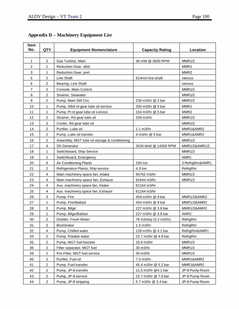
ALDV Design – VT Team 2 Page 100
Appendix D – Machinery Equipment List
Item No. QTY Equipment Nomenclature Capacity Rating Location
1 2 Gas Turbine, Main 36 mW @ 3600 RPM MMR1/2
2 1 Reduction Gear, stbd MMR1
3 1 Reduction Gear, port MMR2
5 2 Line Shaft 614mm line shaft various
6 2 Bearing, Line Shaft various
7 2 Console, Main Control MMR1/2
8 2 Strainer, Seawater MMR1/2
9 2 Pump, Main SW Circ 230 m3/hr @ 2 bar MMR1/2
10 1 Pump, Stbd rd gear lube oil service 200 m3/hr @ 5 bar MMR1
11 1 Pump, Pt rd gear lube oil s ervice 154 m3/hr @ 5 bar MMR2
12 2 Strainer, Rd gear lube oil 200 m3/hr MMR1/2
13 2 Cooler, Rd gear lube oil MMR1/2
14 2 Purifier, Lube oil 1.1 m3/hr MMR1&AMR2
15 2 Pump, Lube oil transfer 4 m3/hr @ 5 bar MMR1&AMR2
16 2 Assembly, MGT lube oil storage & conditioning MMR1/2
17 4 SS Generator 3430 bkW @ 14300 RPM MMR1/2&AMR1/2
18 1 Switchboard, Ship Service MMR1/2
19 1 Switchboard, Emergency AMR1
20 4 Air Conditioning Plants 150 ton 3 RefrigRm&AMR1
21 2 Refrigeration Plants, Ship service 4.3 ton RefrigRm
22 4 Main machinery space fan, Intake 94762 m3/hr MMR1/2
23 4 Main machinery space fan, Exhaust 91644 m3/hr MMR1/2
24 4 Aux. machinery space fan, Intake 61164 m3/hr
25 4 Aux. machinery space fan, Exhaust 61164 m3/hr
26 3 Pump, Fire 454 m3/hr @ 9 bar MMR1/2&AMR2
27 1 Pump, Fire/Ballast 454 m3/hr @ 9 bar MMR1/2&AMR2
28 3 Pump, Bilge 227 m3/hr @ 3.8 bar MMR1/2&AMR2
29 1 Pump, Bilge/Ballast 227 m3/hr @ 3.8 bar AMR2
30 2 Distiller, Fresh Water 76 m3/day (3.2 m3/hr) RefrigRm
31 2 Brominator 1.5 m3/hr RefrigRm
32 4 Pump, Chilled water 128 m3/hr @ 4.1 bar RefrigRm&AMR1
33 2 Pump, Potable water 22.7 m3/hr @ 4.8 bar RefrigRm
35 2 Pump, MGT fuel booster 15.9 m3/hr MMR1/2
36 2 Filter separator, MGT fuel 30 m3/hr MMR1/2
39 2 Pre-Filter, MGT fuel service 30 m3/hr MMR1/2
40 2 Purifier, Fuel oil 7.0 m3/hr MMR1&AMR2
41 2 Pump, Fuel transfer 45.4 m3/hr @ 5.2 bar MMR1&AMR2
42 2 Pump, JP-8 transfer 11.5 m3/hr @4.1 bar JP-8 Pump Room
43 2 Pump, JP-8 service 22.7 m3/hr @ 7.6 bar JP-8 Pump Room
44 2 Pump, JP-8 stripping 5.7 m3/hr @ 3.4 bar JP-8 Pump Room

ALDV Design – VT Team 2 Page 101
Item No. QTY Equipment Nomenclature Capacity Rating Location
45 2 Filter separator, JP-8 transfer 17 m3/hr JP-8 Pump Room
46 2 Filter separator, JP-8 service 22.7 m3/hr JP-8 Pump Room
47 2 Receiver, Starting air 2.3 m3 MMR1/2
48 2 Compressor, Starting air 80 m3/hr @ 30 bar MMR1/2
49 1 Receiver, Ship service air 1.7 m3 MMR1/2
50 1 Receiver, Control air 1 m3 MMR1/2
51 2 Compressor, Air, LP ship service 8.6 bar @194 SCFM MMR1/2
52 2 Dryer, Air 250 SCFM MMR1/2
53 2 Sation, AFFF 227 m3/hr @ 3.8 bar DC Deck
55 1 Unit, Sewage Collection 28 m3 Sewage Rm
57 2 Pump, Oily waste transfer 12.3 m3/hr @ 7.6 bar Sewage Rm
58 2 Separator, Oil/Water 2.7 m3/hr Sewage Rm
59 1 Sewage Plant 45 people Sewage Rm
61 4 SS Reduction Gear MMR1/2&AMR1/2
62 4 SS Engine Enclosure Module MMR1/2&AMR1/2

ALDV Design – VT Team 2 Page 102
Appendix E - Weights and Centers
Abv BL Aft FP Port CL + + + SWBS COMPONENT WT-MT VCG-m Moment LCG-m Moment TCG-m Moment
FULL LOAD WEIGHT + MARGIN 5464.72 7.10 38794.69 97.70 533879.93 0.12 639.38 MINOP WEIGHT + MARGIN 5466.47 5.14 28093.05 96.61 528122.62 0.00 -7.08 LIGHTSHIP WEIGHT + MARGIN 3119.24 6.70 20889.34 97.00 302562.52 0.00 -11.93 LIGHTSHIP WEIGHT 3067.24 6.70 20541.10 97.00 297518.59 0.00 -11.73 MARGIN 52 6.70 348.24 97.00 5043.94 0.00 -0.20
100 HULL STRUCTURES 1625.62 7.58 12324.40 97.50 158463.76 0.00 0.00 BARE HULL 1290.37 7.03 9071.30 98.53 127140.16 0.00 0.00
150 DECK HOUSE STRUCTURE 149.77 14.40 2156.69 100.00 14977.00 0.00 0.00170 MASTS+KINGPOSTS+SERV PLTFRM 2.03 25.00 50.75 100.00 203.00 0.00 0.00180 FOUNDATIONS 183.45 5.70 1045.67 88.00 16143.60 0.00 0.00
200 PROPULSION PLANT 449.32 5.25 2360.23 149.12 67001.63 -0.03 -11.73 BASIC MACHINERY 253.95 5.70 1447.52 132.00 33521.40 0.00 0.00
243 SHAFTING 11.73 3.32 38.94 151.00 1771.23 -1.00 -11.73244 SHAFT BEARINGS 2.76 3.32 9.16 151.00 416.76 0.00 0.00245 PROPULSORS (WATERJETS) 180.88 4.78 864.61 173.00 31292.24 0.00 0.00
300 ELECTRIC PLANT, GENERAL 228.07 6.27 1430.00 97.91 22330.48 0.00 0.00310 ELECTRIC POWER GENERATION
BASIC MACHINERY 188.36 6.27 1181.02 100.00 18836.00 0.00 0.00320 POWER DISTRIBUTION SYSTEM 22.14 6.27 138.82 88.00 1948.32 0.00 0.00330 LIGHTING SYSTEM 17.57 6.27 110.16 88.00 1546.16 0.00 0.00
400 COMMAND+SURVEILLANCE 133.02 10.01 1331.25 71.92 9566.44 0.00 0.00 PAYLOAD 45.02 14.76 664.50 65.00 2926.30 0.00 0.00 SHIP CONTROL SYSTEM 12.15 6.98 84.81 65.00 789.75 0.00 0.00
TOTAL COMMAND AND CONTROL 25.74 5.70 146.72 65.00 1673.10 0.00 0.00430 INTERIOR COMMUNICATIONS 28.37 11.41 323.70 80.00 2269.60 0.00 0.00475 DEGAUSSING SYSTEM 21.74 5.13 111.53 87.75 1907.69 0.00 0.00
500 AUXILIARY SYSTEMS, GENERAL 447.79 4.91 1864.93 66.51 25256.31 0.00 0.00 WAUX 142.40 8.48 1207.55 89.00 12673.60 0.00 0.00 PAYLOAD 237.32 2.77 657.38 53.02 12582.71 0.00 0.00
510 CLIMATE CONTROL
CPS 19.01 0.00 0.00 0.00 0.00 0.00 0.00593 ENVIRON POLLUTION CNTL SYSTEM 10.16 0.00 0.00 0.00 0.00 0.00 0.00598 AUX SYSTEMS OPERATING FLUIDS 38.90 0.00 0.00 0.00 0.00 0.00 0.00
600 OUTFIT+FURNISHING, GENERAL 149.23 7.58 1131.48 79.68 11891.26 0.00 0.00610 SHIP FITTINGS 120.37 7.41 891.94 88.00 10592.56 0.00 0.00640 LIVING SPACES 28.86 8.30 239.54 45.00 1298.70 0.00 0.00
700 ARMAMENT 34.19 2.89 98.81 88.00 3008.72 0.00 0.00
FULL LOAD CONDITION
F00 LOADS 2345.48 7.63 17905.35 98.62 231317.40 0.28 651.31 F10 SHIPS FORCE 5.44 8.35 45.43 65.00 353.60 0.00 0.00 F31 PROVISIONS+PERSONNEL STORES 3.25 5.97 19.39 70.00 227.50 0.00 0.00 F32 GENERAL STORES 1.17 6.75 7.90 70.00 81.90 0.00 0.00 F41 DIESEL FUEL MARINE (DFM) 558.90 7.90 4415.31 96.24 53785.74 0.00 0.00 F46 LUBRICATING OIL 43.00 1.37 58.82 55.58 2389.73 0.98 42.01 F47 SEA WATER BALLAST 0.00 1.29 0.00 84.95 0.00 -0.78 0.00 F52 FRESH WATER 129.00 3.02 389.74 70.19 9054.11 1.58 203.75
SHIP FRESHWATER 87.00 3.72 323.38 57.01 4959.87 2.34 203.75SEWAGE 21.00 1.58 33.18 97.48 2047.12 -3.10 -65.06WASTEWATER 21.00 1.58 33.18 97.48 2047.12 3.10 65.06
F61 ALDS ORDNANCE CARGO DELIVERY SYS 623.96 8.90 5552.28 96.06 59937.80 0.00 0.00ALDS GLIDER COMPONENTS 378.14 13.50 5104.89 100.00 37814.00 0.00 0.00ALDS AMMO MAGAZINES 245.82 1.82 447.39 90.00 22123.80 0.00 0.00
F62 ALDS CARGO - DRY 188.27 5.99 1127.74 75.00 14120.25 0.00 0.00 F63 JP-8 FUEL (V-22 and LAMPS) 706.33 8.45 5968.49 122.40 86454.79 0.00 0.00 F69 ALDS CARGO - FRESHWATER 86.16 3.72 320.26 57.01 4911.98 2.34 201.79

ALDV Design – VT Team 2 Page 103
MIN. OPERATING CONDITION
F00 LOADS 2347.23 3.07 7203.71 96.10 225560.09 0.00 4.85 F10 SHIPS FORCE 5.44 8.35 45.43 65.00 353.60 0.00 0.00 F31 PROVISIONS+PERSONNEL STORES 3.25 5.97 19.39 70.00 227.50 0.00 0.00 F32 GENERAL STORES 1.17 6.75 7.90 70.00 81.90 0.00 0.00 F41 DIESEL FUEL MARINE (DFM) 186.30 5.28 982.92 93.25 17373.22 0.00 0.00 F46 LUBRICATING OIL 14.00 0.81 11.35 55.55 777.71 0.97 13.52 F47 SEA WATER BALLAST 1518.00 1.65 2503.18 99.67 151305.13 -0.14 -204.93 F52 FRESH WATER 57.67 2.32 133.95 76.66 4420.95 1.16 66.85
SHIP FRESHWATER 29.67 3.20 95.06 57.01 1691.49 2.25 66.85SEWAGE 14.00 1.39 19.45 97.48 1364.73 -3.01 -42.10WASTEWATER 14.00 1.39 19.45 97.48 1364.73 3.01 42.10
F61 ALDS ORDNANCE CARGO DELIVERY SYS 205.91 8.71 1794.36 97.03 19979.27 0.00 0.00ALDS GLIDER COMPONENTS 126.05 12.50 1575.58 100.00 12604.67 0.00 0.00ALDS AMMO MAGAZINES 81.94 2.67 218.78 90.00 7374.60 0.00 0.00
F62 ALDS CARGO - DRY 62.76 4.96 311.27 75.00 4706.75 0.00 0.00 F63 JP-8 FUEL (V-22) 235.30 5.14 1209.91 98.00 23059.40 0.00 0.00 F69 ALDS CARGO - FRESHWATER 57.44 3.20 184.04 57.01 3274.65 2.25 129.41
MIN OP: FUEL, STORES, WEAPONS @ 33%POTABLE WATER TANKS @ 66%

ALDV Design – VT Team 2 Page 104
Appendix F – SSCS Space Summary
SSCS GROUP VOLUME M3 AREA M2
TOTAL AVAILABLE 1909.8 5183.87 1 MISSION SUPPORT 83 3317.47
1.1 COMMAND,COMMUNICATION+SURV 185.27 1.11 EXTERIOR COMMUNICATIONS 65.77 1.111 RADIO 65.77
1.112 UNDERWATER SYSTEMS 0 1.113 VISUAL COM 0 1.12 SURVEILLANCE SYS 0
1.121 SURFACE SURV (RADAR) 0 1.122 UNDERWATER SURV (SONAR) 0 1.13 COMMAND+CONTROL 103.3
1.131 COMBAT INFO CENTER 55 1.132 CONNING STATIONS 48.3 1.1321 PILOT HOUSE 30.4
1.1322 CHART ROOM 17.9 1.133 DATA PROCESSING 0 1.14 COUNTERMEASURES 0
1.141 ELECTRONIC 1.142 TORPEDO 1.143 MISSILE
1.15 INTERIOR COMMUNICATIONS 13 1.16 ENVIORNMENTAL CNTL SUP SYS 3.2 1.2 WEAPONS 14.9
1.21 GUNS 14.9 1.211 BATTERIES 0 1.214 AMMUNITION STOWAGE 14.9
1.22 MISSILES 1.24 TORPEDOS 1.26 MINES
1.28 WEAP MODULE STA & SERV INTER 1.3 AVIATION 74.2 1.31 AVIATION LAUNCH+RECOVERY 0
1.311 LAUNCHING+RECOVERY AREAS 0 1.312 LAUNCHING+RECOVERY EQUIP 0 1.32 AVIATION CONTROL 45.8
1.321 FLIGHT CONTROL 12 1.322 NAVIGATION 33.8 1.323 OPERATIONS
1.33 AVIATION HANDLING

ALDV Design – VT Team 2 Page 105
1.34 AIRCRAFT STOWAGE 0 1.342 HELICOPTER HANGAR 1.35 AVIATION ADMINISTRATION 0
1.353 AIR WING 0 1.3536 AVIATION OFFICE 1.36 AVIATION MAINTENANCE 0
1.361 AIRFRAME SHOPS
1.369 ORGANIZATIONAL LEVEL MAINTANENCE
1.37 AIRCRAFT ORDINANCE 0 1.372 CONTROL
1.373 HANDLING 1.374 STOWAGE 1.38 AVIATION FUEL SYS 1062 28.4
1.381 JP-5 SYSTEM 1062 28.4 1.3811 JP-5 TRANSFER 1.3812 JP-5 HANDLING
1.3813 AVIATION FUEL 1062 1.39 AVIATION STORES 1.8 SPECIAL MISSIONS (ALDS) 3034
1.81 ASSEMBLY ROOM 1422 1.82 LIM 703 1.83 DRY CARGO 604
1.84 AMMO 305 1.9 SM ARMS,PYRO+SALU BAT 9.1 1.91 SM ARMS (LOCKER) 9.1
1.92 PYROTECHNICS 1.93 SALUTING BAT (MAGAZINE) 1.94 ARMORY
1.95 SECURITY FORCE EQUIP 2 HUMAN SUPPORT 895.7
2.1 LIVING 453.8 2.11 OFFICER LIVING 120 2.111 BERTHING 16
2.1111 SHIP OFFICER 81.3
2.1111104 COMMANDING OFFICER STATEROOM 24.4
2.1111206 EXECUTIVE OFFICER STATEROOM 23.6 2.111123 DEPARTMENT HEAD STATEROOM 33.3
2.1111302 OFFICER STATEROOM (DBL) 0 2.1114 AVIATION OFFICER 2.112 SANITARY 14.3
2.1121 SHIP OFFICER 14.3 2.1121101 COMMANDING OFFICER BATH 4.2 2.1121201 EXECUTIVE OFFICER BATH 3.5

ALDV Design – VT Team 2 Page 106
2.1121203 OFFICER BATH 0 2.1121303 DEPT HEAD BATH 6.6 2.1124 AVIATION OFFICER
2.12 CPO LIVING 103.6 2.121 BERTHING 73 2.122 SANITARY 30.6
2.13 CREW LIVING 196.5 2.131 BERTHING 119.7 2.132 SANITARY 24.3
2.133 RECREATION 52.5 2.14 GENERAL SANITARY FACILITIES 3 2.142 BRIDGE WASHRM & WC 3
2.143 DECK WASHRM & WC 2.144 ENGINEERING WR & WC 2.15 SHIP RECREATION FAC 19.5
2.151 MUSIC 2.152 MOTION PIC FILM+EQUIP 2.153 PHYSICAL FITNESS
2.154 TV ROOM 2.16 TRAINING 11.2 2.2 COMMISSARY 371.1
2.21 FOOD SERVICE 159.9 2.211 WARDROOM MESSRM & LOUNGE 34.3 2.212 CPO MESSROOM AND LOUNGE 42
2.213 CREW MESSROOM 83.6 2.22 COMMISSARY SERVICE SPACES 81.2 2.221 FOOD PREPARATION SPACES
2.222 GALLEY 77.5 2.2222 WARD ROOM GALLEY 11.5 2.2224 CREW GALLEY 66
2.223 WARDROOM PANTRY 0 2.224 SCULLERY 3.7 2.23 FOOD STORAGE+ISSUE 130
2.231 CHILL PROVISIONS 2.232 FROZEN PROVISIONS 2.233 DRY PROVISIONS
2.3 MEDICAL+DENTAL 22.2 2.4 GENERAL SERVICES 39.2 2.41 SHIP STORE FACILITIES 15.4
2.42 LAUNDRY FACILITIES 23.8 2.44 BARBER SERVICE 2.46 POSTAL SERVICE
2.47 BRIG 2.48 RELIGIOUS 2.5 PERSONNEL STORES 5.6

ALDV Design – VT Team 2 Page 107
2.51 BAGGAGE STOREROOMS 2.52 MESSROOM STORES 2.55 FOUL WEATHER GEAR
2.56 LINEN STOWAGE 5.6 2.57 FOLDING CHAIR STOREROOM 2.6 CBR PROTECTION 0
2.61 CBR DECON STATIONS 2.62 CBR DEFENSE EQUIPMENT 2.63 CPS AIRLOCKS
2.7 LIFESAVING EQUIPMENT 3.8 3 SHIP SUPPORT 1825 691.7
3.1 SHIP CNTL SYS (STEERING) 20.3 3.11 STEERING GEAR 20.3 3.12 ROLL STABILIZATION
3.15 STEERING CONTROL 3.2 DAMAGE CONTROL 58.3 3.21 DAMAGE CNTRL CENTRAL 12.8
3.22 REPAIR STATIONS 34.8 3.25 FIRE FIGHTING 10.7 3.3 SHIP ADMINISTRATION 100
3.301 GENERAL SHIP 22.9 3.302 EXECUTIVE DEPT 20.2 3.303 ENGINEERING DEPT 15.3
3.304 SUPPLY DEPT 15.2 3.305 DECK DEPT 18.9 3.306 OPERATIONS DEPT 7.5
3.307 WEAPONS DEPT 3.31 SHIP PHOTO/PRINT SVCS 3.5 DECK AUXILIARIES 29.1
3.51 ANCHOR HANDLING 29.1 3.52 LINE HANDLING 3.53 TRANSFER-AT-SEA
3.54 SHIP BOATS STOWAGE 3.6 SHIP MAINTENANCE 96.7 3.61 ENGINEERING DEPT 55.3
3.611 AUX (FILTER CLEANING) 3.612 ELECTRICAL 14.2 3.613 MECH (GENERAL WK SHOP) 21.4
3.614 PROPULSION MAINTENANCE 19.7 3.62 OPERATIONS DEPT (ELECT SHOP) 14.3 3.63 WEAPONS DEPT (ORDINANCE SHOP) 6.3
3.64 DECK DEPT (CARPENTER SHOP) 20.8 3.7 STOWAGE 101.3 3.71 SUPPLY DEPT

ALDV Design – VT Team 2 Page 108
3.711 HAZARDOUS MATL (FLAM LIQ) 3.712 SPECIAL CLOTHING 3.713 GEN USE CONSUM+REPAIR PART
3.714 SHIP STORE STORES 3.715 STORES HANDLING 3.72 ENGINEERING DEPT
3.73 OPERATIONS DEPT 3.74 DECK DEPT (BOATSWAIN STORES) 3.75 WEAPONS DEPT
3.76 EXEC DEPT (MASTER-AT-ARMS STOR) 3.78 CLEANING GEAR STOWAGE 3.8 ACCESS 286
3.82 INTERIOR 286 3.821 NORMAL ACCESS 280 3.822 ESCAPE ACCESS 6
3.9 TANKS 1825 3.91 SHIP PROP SYS TNKG 986 3.911 SHIP ENDUR FUEL TNKG 986
3.9111 ENDUR FUEL TANK (INCL SERVICE) 986 3.914 FEEDWATER TNKG 3.92 BALLAST TNKG 732
3.93 FRESH WATER TNKG 87 3.94 POLLUTION CNTRL TNKG 20 3.941 SEWAGE TANKS
3.942 OILY WASTE TANKS 3.95 VOIDS 3.96 COFFERDAMS
3.97 CROSS FLOODING DUCTS 4 SHIP MACHINERY SYSTEM 1.8 279
4.1 PROPULSION SYSTEM 137.3 4.13 INTERNAL COMBUSTION (DIESEL) 4.132 COMBUSTION AIR (INTAKE)
4.133 EXHAUST 4.134 CONTROL 4.14 GAS TURBINE 137.3
4.142 COMBUSTION AIR (INTAKE) 16.8 4.143 EXHAUST 16.8 4.144 CONTROL 19.8
4.2 PROPULSOR & TRANSMISSION SYST 1.8 17 4.23 WATERJET ROOMS 1.8 17 4.23001 PROP SHAFT ALLEY 1.8
4.24 AIR FAN ROOMS 4.3 AUX MACHINERY 124.7 4.32 A/C & REFRIGERATION 73.3

ALDV Design – VT Team 2 Page 109
4.321 A/C (INCL VENT) 4.322 REFRIGERATION 4.33 ELECTRICAL 34.4
4.331 POWER GENERATION 28.8 4.3311 SHIP SERVICE PWR GEN 4.3313 BATTERIES
4.3314 400 HERTZ 4.332 PWR DIST & CNTRL 5.6 4.334 DEGAUSSING
4.34 POLLUTION CONTROL SYSTEMS 17 4.341 SEWAGE 14 4.342 TRASH 3
4.35 MECHANICAL SYSTEMS 4.36 VENTILA TION SYSTEMS

ALDV Design – VT Team 2 Page 110
Appendix G – ALDS Executive Summary
The Advanced Logistics Delivery System (ALDS) will be used to transport supplies to troops in hostile territories as an alternative to previously implemented techniques such as convoy lines and airdrops, which endanger soldiers and military personnel. The ALDS is a glider that is launched from a ship located at a safe distance off the shore of hostile territories. The glider’s compact launch vehicle will be accelerated down a track that runs along the keel, propelled by an electromagnetic motor system. This glider is then launched at an initial speed of 500 knots and an initial acceleration of 30g’s. The glider will travel in its compact state until it reaches the apex of its flight. At that point inflatable wings stored inside the glider launch vehicle will deploy and carry the glider to its 50 mile range destination. The design premise for this glider comes from the Center for Innovation in Ship Design (CISD) at the Naval Surface Warfare Center – Carderock Division (NSWCCD).
An analysis of the glider’s aerodynamics, structures, inflatable wings, stability and control, weights and center of gravity, avionics system, sizing, and cost was performed. The final schematic of the glider design is shown in the following figures.
Figure 1 - Final Glider Design
Figure 2 - Dimensioned Side Profile of Final Glider Design

ALDV Design – VT Team 2 Page 111
Figure 3 - Internal View of Final Glider Design