advanced lighting control systems for specifiers lighting control systems for specifiers may 21,...
TRANSCRIPT

1
1
Advanced Lighting Control Systems for
SpecifiersMay 21, 2011
IEEE PES Cal Poly Student Branch
Rick Miller, PE, LC, LEED® APRNM Engineering, Inc.
2
Learning Objectives
• Define functionality and scope of a lighting control system.
• Review lighting control strategies• Learn how to write control narratives, and
develop schedules and drawings for lighting control systems.
• Explore differences between hardwired analog and “plug-and-play” digital systems.

2
3
History of this Seminar
• CALCTP – 40 hours for electricians.• Electricians install only what is in the
contract.• Need to teach designers and specifiers.• Lighting Control Components Workshop• Lighting Control Systems for Specifiers• Development of this seminar was
cofunded by PG&E and SCE.
4
This Seminar
• From Concept• To Construction
of lighting control systems
3
5
This Seminar is NOT
• A review of the Electrical Code• A course on LEED®
• A primer on Title 24• A tutorial on dimmer electronics
6
Agenda• Factors To Consider • Lighting Control Strategies• Design Process• Lighting Control Components• Dimming Technologies • Control Narratives• Hardware, Protocols, Systems• Research , Incentives• How to Convey the Control System Design
4
7
Factors To Consider When Specifying A
Control System
8
Factors to Consider
• Control Theory• Lighting Control Strategies• Design Process• Lighting Control Components• Dimming Technologies

5
9
Control Theory
• Sensor (Input) - e.g. Pushbutton– Provides information to logic circuit
• Controller (Algorithm/Process) - e.g Relay– Decides On/Off or how much
• Actuator (Output) - e.g. Lamp– The output changes
Sensor /Controls Controller Loads
10
Control Theory
• Open Loop• Closed Loop

6
11
Open Loop Control SystemController
PhotosensorLamp
Ballast
Surface
Electric Light
Daylig
ht
12
Closed Loop Control SystemController
PhotosensorLamp
Ballast
Surface
Electric LightRefl
ected
Ligh
t

7
13
Controller
PhotosensorLamp
Ballast
Surface
Electric LightRefl
ected
Ligh
t
Daylight
Closed Loop Control System
14
Controller
PhotosensorLamp
Ballast
Surface
Electric LightRefl
ected
Ligh
t Daylight
Daylight
Daylight
Closed Loop Control System
Avoid
Electric LightAvoid

8
15
Lighting Control Strategies
16
Lighting Control Strategies
• Local Controls (room)• Building Level Controls

9
17
Lighting Control Strategies
Local Controls• Multi-Level Switching• Occupancy/Vacancy Sensing• Daylight Harvesting• Architectural Dimming • Personal Tuning
18
Multi-Level Switching
Local Control– OFF, mid level (30-70%), Full ON
• Could be 0-50-100 or 0-33-66-100– Commonly referred to as “a/b switching”– Dimming is acceptable compliance
10
19
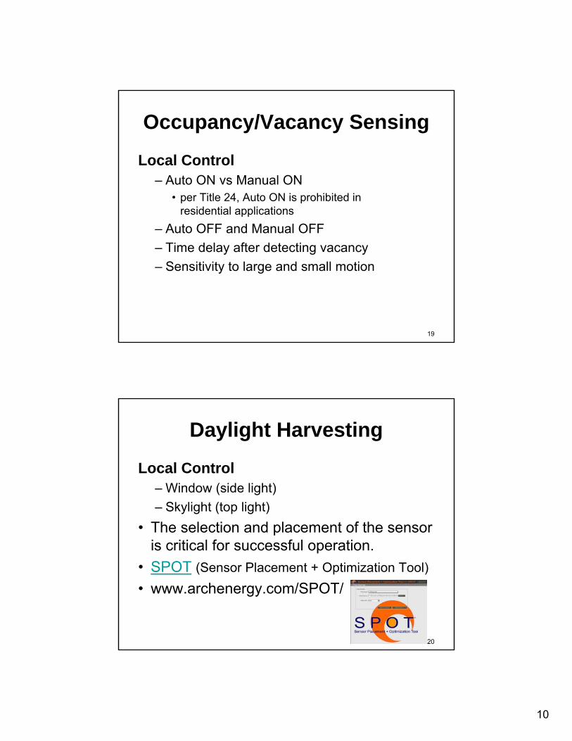
Occupancy/Vacancy Sensing
Local Control– Auto ON vs Manual ON
• per Title 24, Auto ON is prohibited in residential applications
– Auto OFF and Manual OFF– Time delay after detecting vacancy– Sensitivity to large and small motion
20
Daylight Harvesting
Local Control– Window (side light)– Skylight (top light)
• The selection and placement of the sensor is critical for successful operation.
• SPOT (Sensor Placement + Optimization Tool)• www.archenergy.com/SPOT/
11
21
Architectural Dimming
Local Control– Functional– Aesthetic / Artistic
22
Personal Tuning
Local Control– Adjust for the task at hand– Adjust for comfort
12
23
Lighting Control Strategies
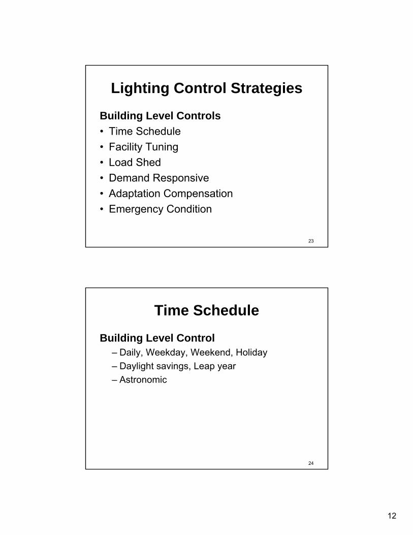
Building Level Controls• Time Schedule• Facility Tuning• Load Shed• Demand Responsive• Adaptation Compensation• Emergency Condition
24
Time Schedule
Building Level Control– Daily, Weekday, Weekend, Holiday– Daylight savings, Leap year– Astronomic

13
25
Facility Tuning
Building Level Control– Set for reduced power– Lumen maintenance
26
Load Shed
Building Level Control– Demand peak reduction
• Initiated by owner• Peak shave for demand reduction
14
27
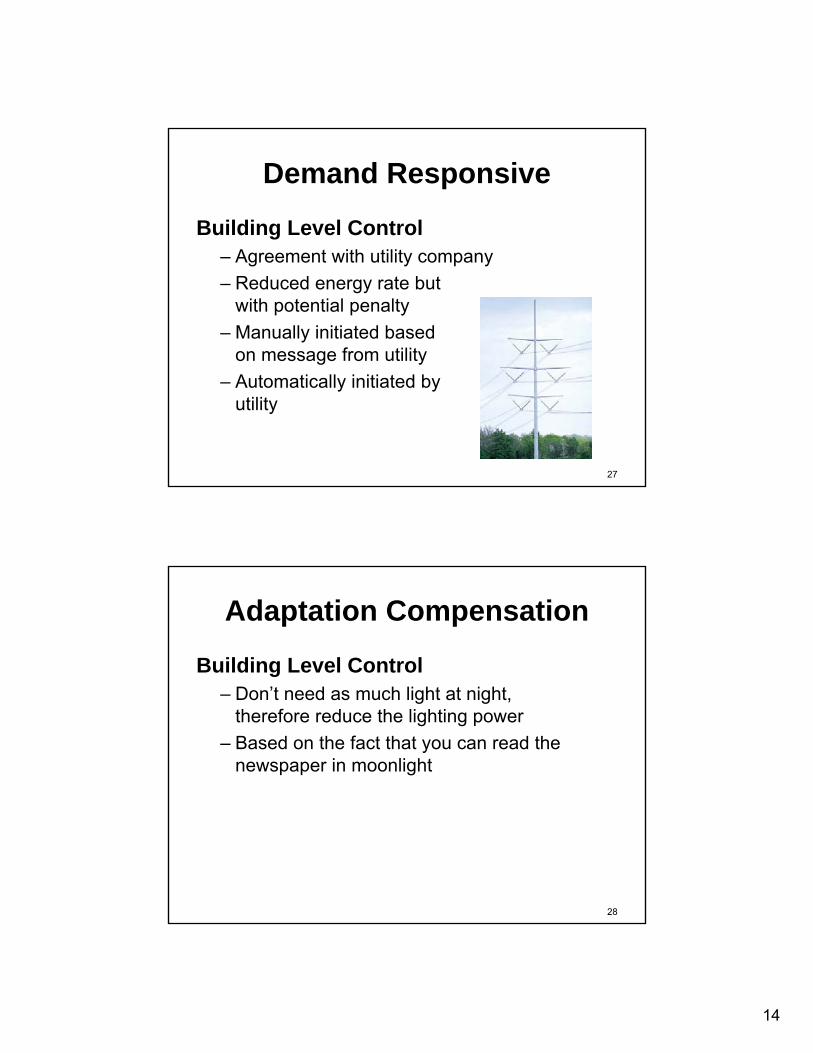
Demand Responsive
Building Level Control– Agreement with utility company– Reduced energy rate but
with potential penalty– Manually initiated based
on message from utility– Automatically initiated by
utility
28
Adaptation Compensation
Building Level Control– Don’t need as much light at night,
therefore reduce the lighting power– Based on the fact that you can read the
newspaper in moonlight

15
29
Emergency Condition
Building Level Control– National Fire Protection Association -
NFPA-101 Life Safety Code– California Building Code (CBC)– National Electrical Code - NEC®
– Underwriters Laboratory -UL924 - Shunt relay
– Underwriters Laboratory -UL1008 - Transfer switch
30
NFPA-101 Life Safety Code
7.8 Illumination of Means of Egress7.8.1.2 When NeededThe LSC says that the means of egress
shall be illuminated during periods of occupancy
7.9 Emergency Lighting7.9.2.7 Lighting Can be ControlledLights on continuously, or else will come on
automatically.

16
31
NEC® Art.700
NEC 700.20 – Switch Requirements• Switches in emergency lighting circuits
shall be arranged so that only authorized persons control the lights.
• Exceptions:– Multiple parallel switches OK as long as one
of them is controlled by authorized people
32
Applications for UL924
• Control emergency lighting that otherwise would burn 24/7.
• Bypass a dimmer or a switch.

17
33
Stairwell Energy Savings
Photo courtesy of www.occu-smart.com
34
Design Process
18
35
Design Process
• Owner Project Requirements - OPR• Basis of Design - BOD
36
Energy Codes
• International Energy Conservation Code –IECC
• American Society of Heating Refrigeration & Air Conditioning Engineers / Illuminating Engineering Society – ASHRAE/IES 90.1
• California Energy Code, aka Title 24– Watts per Square Foot
W/SF (not scope of this seminar)– Components are appliances, therefore
covered in Title 20

19
37
Title 24 but also Title 20• Automatic Off
– Vacancy sensing– Photo switch (for outdoor)– Time schedule or Curfew
• Reduction or Dimming– a/b switching – manual– a/b switching - automatic– dimming – manual– dimming – automatic
• Acceptance Testing(By licensed person)– Architect– Engineer– Contractor http://www.energy.ca.gov/2008publications/
CEC-400-2008-001/CEC-400-2008-001-CMF.pdf
38
Power Adjustment Factors
20
39
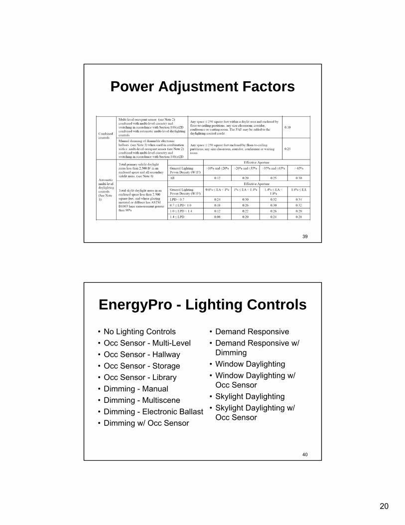
Power Adjustment Factors
40
EnergyPro - Lighting Controls• No Lighting Controls• Occ Sensor - Multi-Level• Occ Sensor - Hallway• Occ Sensor - Storage• Occ Sensor - Library• Dimming - Manual• Dimming - Multiscene• Dimming - Electronic Ballast• Dimming w/ Occ Sensor
• Demand Responsive• Demand Responsive w/
Dimming• Window Daylighting• Window Daylighting w/
Occ Sensor• Skylight Daylighting• Skylight Daylighting w/
Occ Sensor
21
41
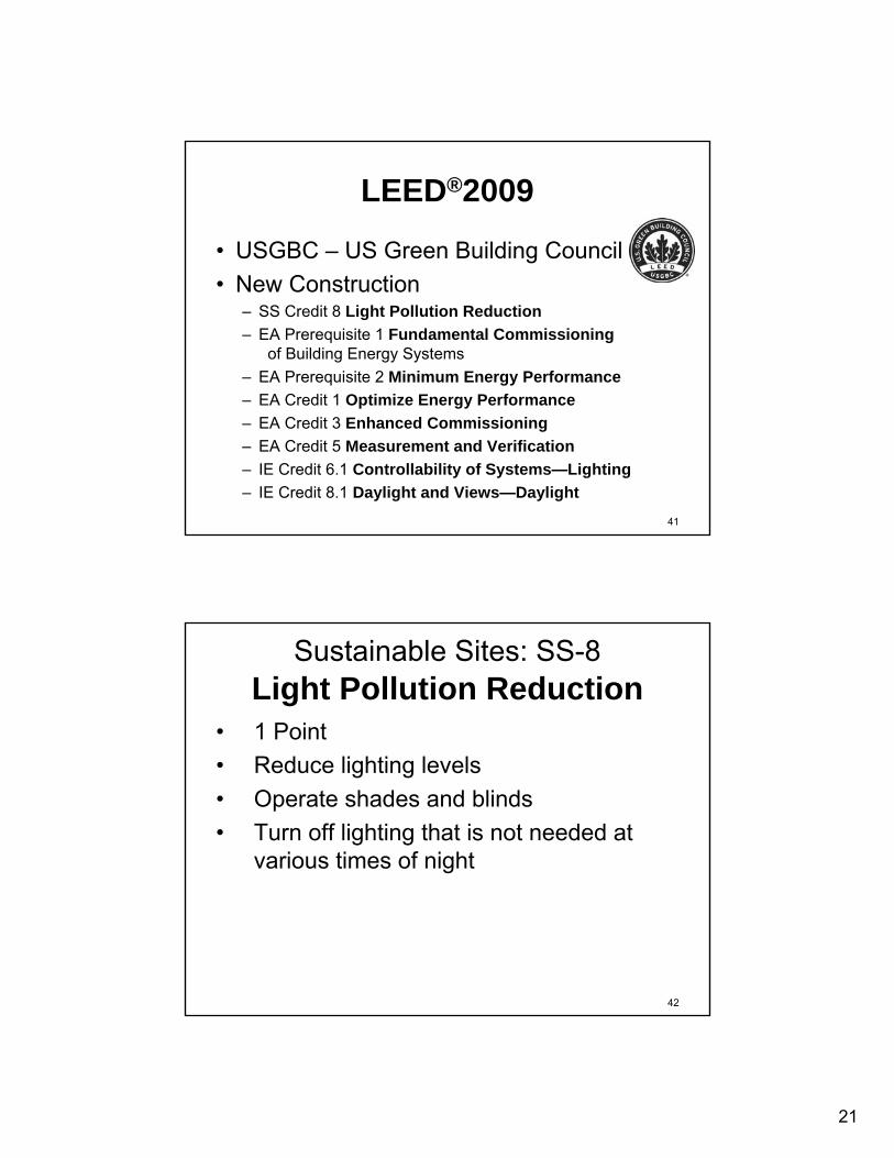
LEED®2009
• USGBC – US Green Building Council• New Construction
– SS Credit 8 Light Pollution Reduction– EA Prerequisite 1 Fundamental Commissioning
of Building Energy Systems– EA Prerequisite 2 Minimum Energy Performance– EA Credit 1 Optimize Energy Performance– EA Credit 3 Enhanced Commissioning– EA Credit 5 Measurement and Verification– IE Credit 6.1 Controllability of Systems—Lighting– IE Credit 8.1 Daylight and Views—Daylight
42
Sustainable Sites: SS-8Light Pollution Reduction
• 1 Point• Reduce lighting levels• Operate shades and blinds• Turn off lighting that is not needed at
various times of night

22
43
Energy & Atmosphere: EA Prereq 1 Fundamental Commissioning• Prerequisite (Required)• The owner prepares the OPR• The design team develops the BOD• The Commissioning Authority (CxA)
verifies Lighting and Daylighting Controls
44
Energy & Atmosphere: EA Prereq 2 Minimum Energy Performance• Prerequisite (Required)• Title 24-2005, Part 6 • Regulated (non-process) energy includes
lighting (for the interior, parking garage, surface parking, façade, or building grounds)
• Predicted energy use must be not less than 10% below the applicable standard (T24)
23
45
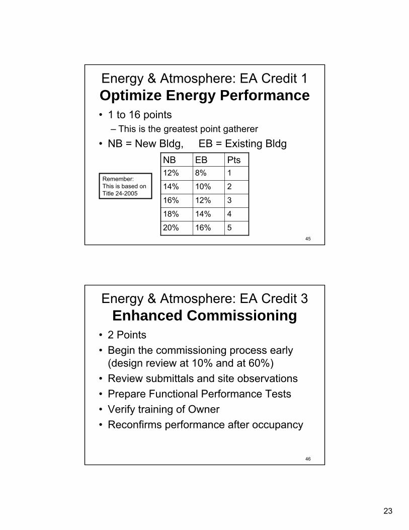
Energy & Atmosphere: EA Credit 1Optimize Energy Performance• 1 to 16 points
– This is the greatest point gatherer• NB = New Bldg, EB = Existing Bldg
516%20%
414%18%
312%16%
210%14%
18%12%PtsEBNB
Remember:This is based on Title 24-2005
46
Energy & Atmosphere: EA Credit 3Enhanced Commissioning
• 2 Points• Begin the commissioning process early
(design review at 10% and at 60%)• Review submittals and site observations• Prepare Functional Performance Tests• Verify training of Owner• Reconfirms performance after occupancy

24
47
Energy & Atmosphere: EA Credit 5Measurement and Verification• 3 Points • Provide for the ongoing accountability of
building energy consumption over time• International Performance Measurement &
Verification Protocol (IPMVP) Volume III• Install metering equipment to measure
energy use
48
Indoor Environmental: IE Credit 6.1Controllability of Lighting
• 1 Point• Provide individual lighting controls
– For not less than 90% of the building occupants– Adjustments to suit individual task needs and
preferences
• Provide lighting system controls in multi-occupant spaces– Adjustments that meet group needs and preferences
• Controls may be: on/off, multi-level, dimming, task/ambient

25
49
Indoor Environmental: IE Credit 8.1Daylight
• 1 Point• Design the building to maximize interior
daylighting– Automatic photocell-based controls reduce
energy use– The real point grabber is in the EA Credit 1
Optimize Energy Performance
50
BREAK
26
51
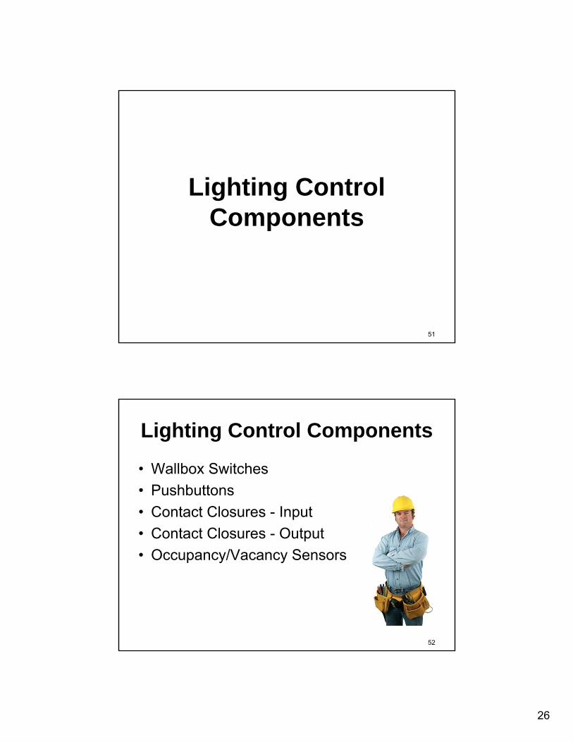
Lighting Control Components
52
Lighting Control Components
• Wallbox Switches• Pushbuttons • Contact Closures - Input • Contact Closures - Output• Occupancy/Vacancy Sensors

27
53
Lighting Control Components
• Photosensor for Outdoor • Photosensor for Indoor • Time Schedule • Architectural Dimming • Emergency Condition • User Interface / Dashboard
54
Switches
• Single pole switch (SPST)• 3-way switch (SPDT)• 4-way switch (DPDT)

28
55
Pushbuttons– single button– multi button keypad– touch screen display– keypad locations– drawing symbol– single press, double press, press and hold– action – select preset, raise, lower, toggle,
dim up/down, on, off– button labels
56
Contact Closures - Input– from security system– from door or partition system– from another automated system such as
Energy Management System (EMS), orBuilding Automation System (BAS)
– from utility Demand event

29
57
Contact Closures - Output– to Audio/Video (A/V) system– to Window shades/blinds– to EMS/BMS/BAS
58
Relays & Contactors
• Relays• Contactors
Photos courtesy of GE and Square D

30
59
Multi-Pole Lighting ContactorPanelboardCircuit BreakersLighting Branch CircuitMulti-Pole Lighting Contactor
Magnetic latching coilNeutral
A B C
Photo courtesy of Square D
60
Power Contactor
Neutral
A B C
Power ContactorElectrically held coil
Photo courtesy of Square D

31
61
Remote Control Circuit Breaker
Neutral
A B C
Smart PanelboardRemote Control Circuit BreakersLighting Branch Circuit
Controller
Photos courtesy of Square D
62
Occupancy/Vacancy Sensors– Occupancy Sensor Technologies
• Infrared• Ultrasonic• Audiophonic• Dual technology
– Sensor Location– Delay setting– Sensitivity setting– Mounting:
• Ceiling, Wall/Corner, Wallbox, Task, Luminaire
Photo courtesy of The Watt Stopper
32
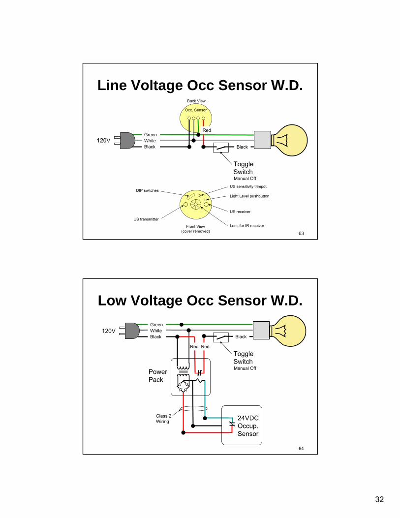
63
GreenWhiteBlack
120V
Occ. Sensor
Back View
Red
Manual Off
Black
Toggle Switch
US receiver
US transmitterLens for IR receiver
DIP switchesUS sensitivity trimpot
Light Level pushbutton
Front View(cover removed)
Line Voltage Occ Sensor W.D.
64
Manual OffPower Pack
Red Red
Class 2Wiring
Black
Toggle Switch
120V
24VDC Occup. Sensor
GreenWhiteBlack
Low Voltage Occ Sensor W.D.

33
65
Photosensor for Outdoor– On/Off adjustable setting– Time delay– Deadband
Photos courtesy of The Watt Stopper
66
Photosensor for Indoor– Sensor response characteristics– Sensor location & orientation– Open loop, closed loop
Photos courtesy of The Watt Stopper

34
67
Timer Switch– Manual ON, Manual OFF, Automatic OFF– Time duration adjustable– Warning prior to shutoff: audible, visual– Low-cost alternative to an occupancy sensor– Leaves lights on for a pre-set period of time– Install in place of a wall switch– Used in storage rooms,
copy rooms, etc.
Photo courtesy of The Watt Stopper
68
Countdown Timer Display
On/Off Switch
Ground the case
120VGreenWhiteBlack
Timer Switch Wiring Diagram
Photo courtesy of The Watt Stopper

35
69
Time Schedule - Time Switch– Time-of-day – Day-of week– Holiday– Backup power– Output signal
• Single pole or multi-pole• Power rated contacts (maintained: NO, NC)
(power rated means 20A, 120V or 277V)• Signal duty contacts (maintained or momentary)
(signal duty is low voltage, low amperage)
70
Astronomic Time Switch– Same as Time Switch + – dawn, dusk, offsets– Latitude, Longitude, Time Zone, ZIP code
Photo courtesy of Tork

36
71
Architectural Dimming
• Wallbox dimmers– Single gang– Line voltage: 2-wire, or 3-wire– 0-10VDC– Digital Addressable
Lighting Interface (DALI)– Multi-scene, multi-channel
• Dimming Panels
Photo courtesy of LUTRON
72
Emergency Condition– Code required egress lighting
• NFPA 101• NEC 700.4
– Night lights– Transfer switch:
double pole, double throw (DPDT)• When switching the Hot, must also switch the
Neutral
37
73
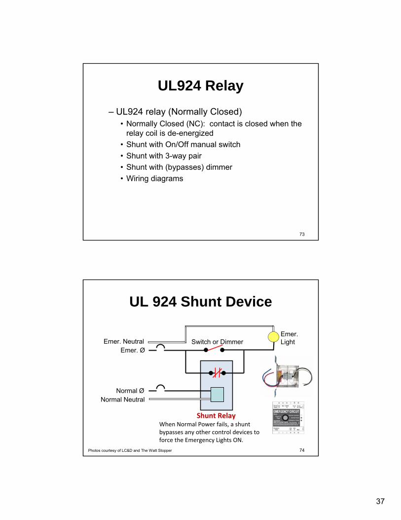
UL924 Relay– UL924 relay (Normally Closed)
• Normally Closed (NC): contact is closed when the relay coil is de-energized
• Shunt with On/Off manual switch• Shunt with 3-way pair• Shunt with (bypasses) dimmer• Wiring diagrams
74
UL 924 Shunt Device
Normal Ø
Emer. NeutralEmer. Ø
Normal Neutral
Shunt RelayWhen Normal Power fails, a shunt bypasses any other control devices to force the Emergency Lights ON.
Photos courtesy of LC&D and The Watt Stopper
Switch or DimmerEmer. Light

38
75
UL1008 Auto Transfer Switch
Normal Ø
Emer. Ø
Normal Neutral
Emer. NeutralEmer.Light
Automatic Transfer Switch
Automatic Transfer Switch:•EM light connected to EM Source only in EM condition,
otherwise connected to Normal Source •Senses when Normal Source fails and transfers to the Emergency Source.
•When switching the Hot between sources, must also switch the Neutral.
•Double pole, double throw (DPDT)
76
User Interface / Dashboard– Information reported
• Real-time power• Energy history (trends)
– Controls / System Commands
39
77
Dimming Technologies
78
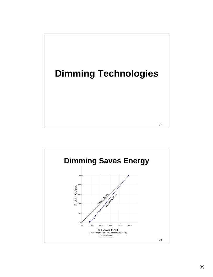
0%
20%
40%
60%
80%
100%
0% 20% 40% 60% 80% 100%
% Power Input
% L
ight
Out
put
Ideal
Curve
Actual
Curve
(Three brands of DALI dimming ballasts)Courtesy of LBNL
Dimming Saves Energy

40
79
Perceived vs Measured Light
% Relative Light Perceived
%R
elat
ive
Ligh
tMea
sure
d
100
2025
50
10
60
40
80
70
90
30
77
010 20 30 40
5060 70 80 90 1000
5
22
IES Handbook - 9th Ed
80
DALI Logarithmic Dimming
Rel
ativ
e Li
ght (
%)
8-bit Control Level
50% = 22925% = 204
12.5% = 178

41
81
Dimming Technologies• Step Dimming (0-50-100), (0-33-66-100)• 2-Wire Line Voltage Dimming
– Forward Phase Control – Reverse Phase Control
• 3-Wire Line Voltage Fluorescent Dimming – Power – Class 1
• (4-Wire) Low Voltage 0–10VDC• (4-Wire) Low Voltage DALI • Pulse Width Modulation (PWM)
82
Dual Signal Dimming Ballasts
• 2-Wire & 0-10VDC • 3-Wire & DALI • 0-10VDC & DALI
42
83
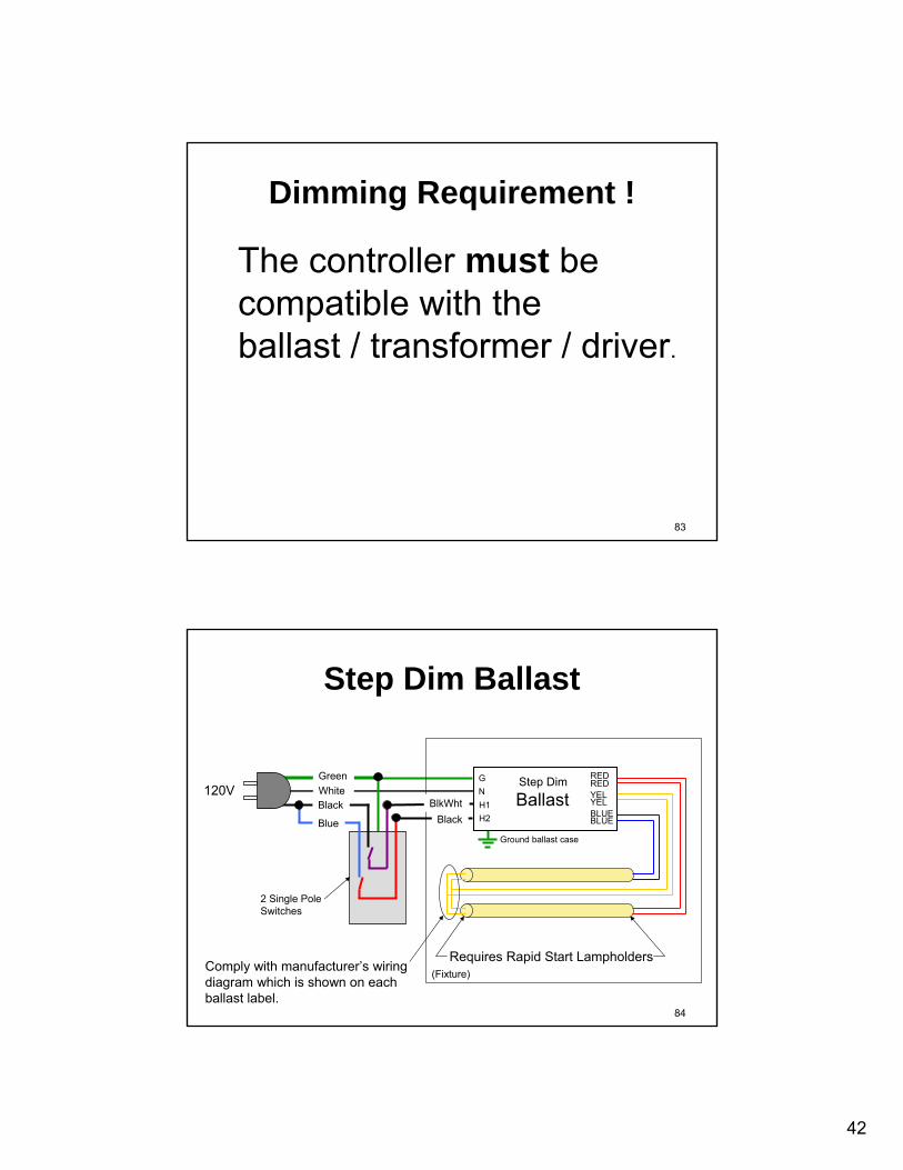
Dimming Requirement !
The controller must be compatible with theballast / transformer / driver.
84
REDREDYELYELBLUEBLUE
BallastGN
Requires Rapid Start Lampholders
Ground ballast case
(Fixture)
Step Dim Ballast
H1H2
Step Dim
BlkWhtBlack
GreenWhite
2 Single PoleSwitches
Black
Blue
120V
Comply with manufacturer’s wiring diagram which is shown on each ballast label.

43
85
DimmerSwitch
120VGreenWhiteBlack
2-Wire Phase Control Dimmer
(Fixture)
86
DimmerSwitch
MagneticTransformer
GNH
Ground xfmr case
120VGreenWhiteBlack
(Fixture)
Forward Phase Control Dimmer
12 Volts
44
87
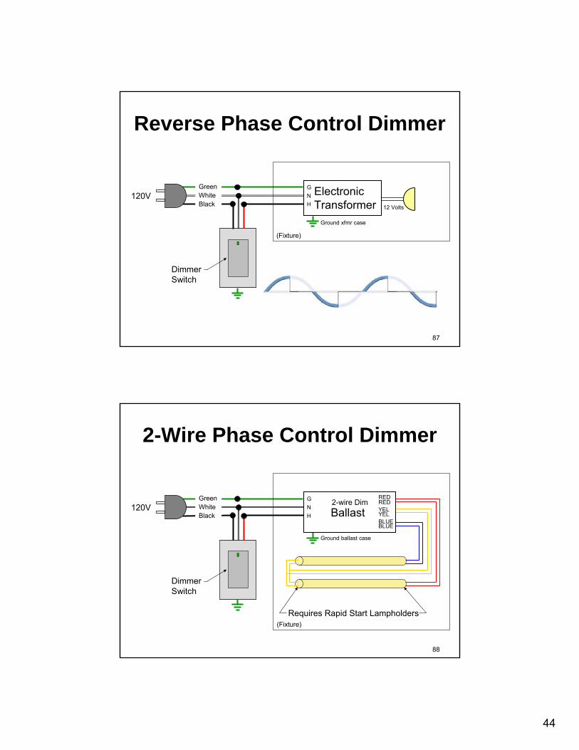
DimmerSwitch
ElectronicTransformer
GNH
Ground xfmr case
120VGreenWhiteBlack
(Fixture)
Reverse Phase Control Dimmer
12 Volts
88
DimmerSwitch
REDREDYELYELBLUEBLUE
BallastGNH
Requires Rapid Start Lampholders
Ground ballast case
120VGreenWhiteBlack
2-wire Dim
(Fixture)
2-Wire Phase Control Dimmer

45
89
REDREDYELYELBLUEBLUE
BallastGNSH
Requires Rapid Start Lampholders
Ground ballast case
DHBlack
Orange
DimmerSwitch
120VGreenWhiteBlack
3-wire Dim
RedYellow
(Fixture)
3-Wire Phase Control Dimmer
90
REDREDYELYELBLUEBLUE
BallastGNH
Requires Rapid Start Lampholders
Ground ballast case
+-
RedViolet
Gray
ON OFFDimmerSwitch
120VGreenWhiteBlack
0-10V Dim
(Fixture)
0-10VDC Dimming

46
91
REDREDYELYELBLUEBLUE
BallastGNH
Requires Rapid Start Lampholders
Ground ballast case
DADA
PurplePurple
DimmerPushbutton
120VGreenWhiteBlack
DALI Dim
PowerSupply
(Fixture)
DALI Dimming
92
White LEDs
White LEDs
White LEDs
White LEDs
PWM to LEDs
REDBLKLED Driver
GNH
Ground driver case
+-
RedViolet
Gray
ON OFFDimmerSwitch
120VGreenWhiteBlack
0-10V Dim
(Fixture)
PWM Dimming of White LEDsUsing 0-10VDC Control

47
93
Blue LEDs
Green LEDs
Red LEDs
PWM to LEDs
GRNBLKLED Driver
GNH
Ground driver case
DMX input
Red
DMX Signal
ON OFF
DMX512Controller
120VGreenWhiteBlack
DMX512
(Fixture)
Color Mixing of RGB LEDsUsing DMX512 Control
REDBLK
BLUBLK
94
Dimming Requirement !
The controller must be compatible with theballast / transformer / driver.

48
95
LUNCH(30 Minutes)
96
Sidebar Special
• Wiring between Ballasts and Lamps • Lampholders

49
97
One Manufacturer has said:• “Most of our 2L T8 dimming ballasts use parallel
wired ‘yellow’ filaments.But we do have some 2L T8 dimming ballasts that use series wired ‘yellow’ filaments.”
• “Most of our 2L T5 dimming ballasts use series wired ‘yellow’ filaments.But we do have some 2L T5 dimming ballasts that use parallel wired ‘yellow’ filaments.”
• “So the bottom line is to check cutsheets and ballast labels.”
98
Ballast/Lamp Wiring• Twisted/Bundled is OK for Instant Start, • Not acceptable for Program Start or
Dimming.Twisted Bundled

50
99
Fluorescent Lampholders• Tall vs Short• Remember that the lamp must be within
1/2” of a grounded metal surface
100
Fluorescent Lampholders
• Surface contact vs Knife-edge contact
51
101
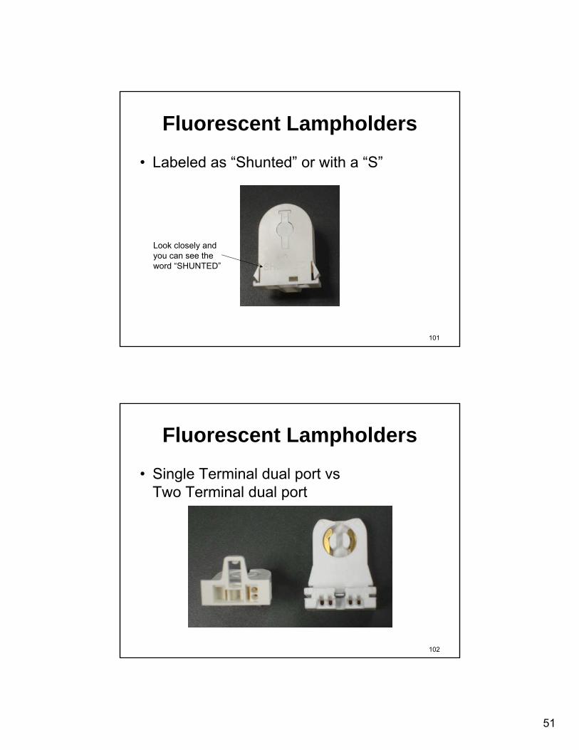
Fluorescent Lampholders
• Labeled as “Shunted” or with a “S”
Look closely and you can see the word “SHUNTED”
102
Fluorescent Lampholders
• Single Terminal dual port vsTwo Terminal dual port

52
103
LUNCH(30 Minutes)
104
Control Narratives

53
105
Sample Narratives
• Sequence of Operation: Wallbox Occupancy Sensors in storage rooms, janitor closets, etc: Set the time delay to 5 minutes. Enabled the Audible and Visible Alert functions
106
Strategies for Room Types
• From the Department Of Energy (DOE): – Commercial Lighting Solutions– www.lightingsolutions.energy.gov

54
107
Commercial Lighting Solutions
• Box Retail: Dropped Ceiling• Box Retail: Open Ceiling• Grocery Store• Pharmacy• Specialty Market• Office
108
Dual general lighting zones (light level switching ballast) controlled by switches integral to a wallbox vacancy sensor (or stand-alone switches if vacancy sensor alternately mounted).General lighting zone controlled by integral dual-switch wallbox vacancy sensorThe vacancy sensor may be located at the wall switch, corner mounted over the door or ceiling mounted
Control Zone Description
Commercial Lighting Solutions

55
109
Sample Narrative from DOE
• Robust option combining the energy saving of occupancy-based automatic shutoff with flexible multilevel switching.– A vacancy sensor will turn the lights off when
the space is unoccupied.– The occupant will turn the lights on to one or
two increments between off and full light output using two manual switches installed at the wallbox using either stand alone switches or switches integral to a wall switch vacancy sensor. (cont.)
110
Sample Narrative from DOE– The vacancy sensor will feature a time delay
setting that is short enough to achieve intended energy savings (and meet code requirements) but long enough to avoid significant reductions in lamp life due to very frequent switching.
– A vacancy sensor time delay of at least 15 minutes is recommended. If programmable time delays are enabled by the control system, the time delay can be shortened to about 5 minutes after normal operating hours.

56
111
Strategies for Room Types
• From the New Building Institute: – Advanced Lighting Guidelines– www.algonline.org
112
Advanced Lighting Guidelines
• Large Private Office• Medium Private Office• Small Private Office (2)• Open Office• Conference Room (3)• Classroom (4)• Warehouses (2)• Big Box Retail

57
113
Advanced Lighting Guidelines
114
Sample Narrative from ALG
• Control Strategy Office Example #3A– Upon entering the room, the sensor will detect
the occupant and trigger the lights ON. Once the room is vacated, the sensor will turn the lights OFF after the time-out has expired. The dual-technology sensor is adjusted to turn ON using PIR detection, and once the lights are ON, the ultrasonic technology will keep the lights ON.
58
115
Sample Narrative from ALG
• Control Strategy Office Example #3B– Upon entering the room, the sensor will detect
the occupant and trigger the lights ON. The photocell will report the level of daylight within the space to the controller, which will in turn adjust the ambient electric light level in the room. As in #3A, the lights will be triggered OFF after the user-defined time-out has expired.
116
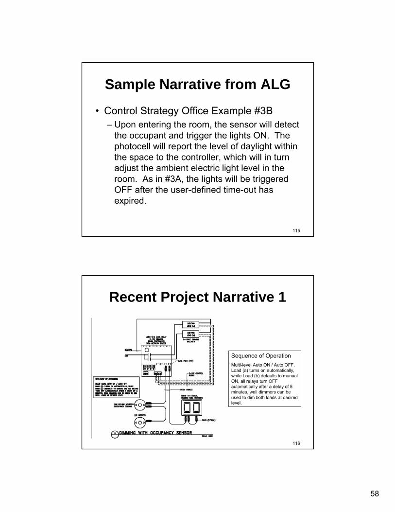
Recent Project Narrative 1
Sequence of OperationMulti-level Auto ON / Auto OFF, Load (a) turns on automatically, while Load (b) defaults to manual ON, all relays turn OFF automatically after a delay of 5 minutes, wall dimmers can be used to dim both loads at desired level.

59
117
Recent Project Narrative 2
Sequence of OperationMulti-level Auto ON / Auto OFF, Load (a) turns on automatically, while Loads (b) and (c) defaults to manual ON, all relays turn OFF automatically after a delay of 5 minutes, when ambient light levels exceed the off setpointLoad (a) turns OFF.
118
Hardware, Protocols, & Systems

60
119
Hardware
• Topology• Medium• Connectors
120
Topology
Ring
Mesh
Star Fully Connected
Line
Daisy Chain
Free Topology
Bus
Simplex
Duplex

61
121
Medium
• 2 wire to contact closure• RS232• RS485• Ethernet• USB• IR• Wireless RF
122
Connectors
• Screw terminals• Pigtails• Twist wire nuts• Pushin• Lever• Insulation piercing
• RJ11• RJ45• 5 pin DIN• DB9• DB25
62
123
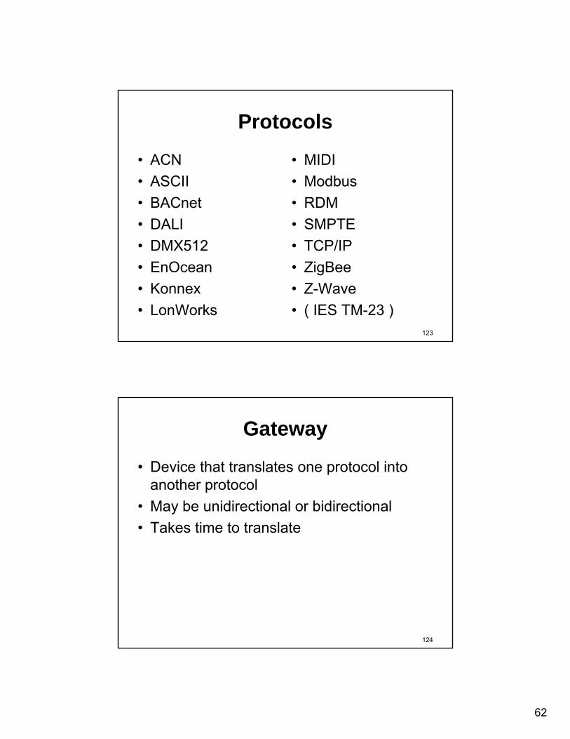
Protocols
• ACN• ASCII• BACnet• DALI• DMX512• EnOcean• Konnex• LonWorks
• MIDI• Modbus• RDM• SMPTE• TCP/IP• ZigBee• Z-Wave• ( IES TM-23 )
124
Gateway
• Device that translates one protocol into another protocol
• May be unidirectional or bidirectional• Takes time to translate

63
125
Systems
• Wired– Centralized– Distributed
• Wireless– Mesh Network– Micro Power
126
Wired - Centralized

64
127
Wired - Distributed
128
Wireless

65
129
Relay Systems
• Central Panels in electrical rooms– Lighting branch circuit control– Long homeruns– Local low voltage & override switches– Local latching line voltage switches
• Distributed Boxes in ceiling above respective rooms
• Inputs (Sw, OS, PS):– Homerun to central panel– Discrete wiring or digital
130
Relay Systems
BAS - Bldg Automation SystemC/B - Circuit BreakerDS - Digital SwitchLCS - Lighting Control System
NON - Non-dim LuminaireOS - Occupancy SensorPS - Photo Sensor RC - Remote Control
Legend

66
131
Remote Control Circuit Breaker
• Circuit breaker has integral motor operated contactor
• Motor operated contactor attached to load terminal of standard circuit breaker
132
Remote Control Circuit Breaker
BAS - Bldg Automation SystemC/B - Circuit BreakerDS - Digital SwitchLCS - Lighting Control System
NON - Non-dim LuminaireOS - Occupancy SensorPS - Photo Sensor RC - Remote Control
Legend
67
133
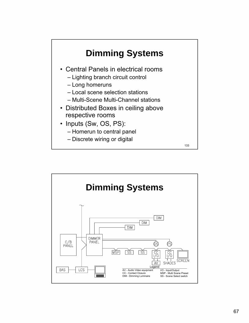
Dimming Systems• Central Panels in electrical rooms
– Lighting branch circuit control– Long homeruns– Local scene selection stations– Multi-Scene Multi-Channel stations
• Distributed Boxes in ceiling above respective rooms
• Inputs (Sw, OS, PS):– Homerun to central panel– Discrete wiring or digital
134
Dimming Systems
AV - Audio Video equipmentCC - Contact ClosureDIM - Dimming Luminaire
I/O - Input/OutputMSP - Multi Scene PresetSS - Scene Select switch
Legend

68
135
Local Digital Networks (DALI)
• Digital Addressable Lighting Interface (DALI) Protocol
• Components• Wiring• Systems integration• Integration with BAS
– Access to lighting system information– Access to setpoints, control templates
• Wireless
136
Local Digital Networks (DALI)Single Room Application
DALI - DALI Dimming BallastDS - DALI Switch
OS - DALI Occupancy SensorPS - DALI Photo Sensor RLY - DALI Relay
Legend

69
137
Local Digital Networks (DALI)
DALI - DALI Dimming BallastDS - DALI SwitchIDD - Incandescent DALI DimmerBAS - Bldg Automation System
OS - DALI Occupancy SensorPS - DALI Photo Sensor RLY - DALI RelayLCS - Lighting Control System
Legend
System Application
138
Digital Component System
• Modular per room• Module per luminaire• Plug-and-Play components
– Occupancy sensor– Photo sensor– Scene control– Handheld control– Remote commissioning
• Integration with BAS– Access to energy information– Access to setpoints, control templates

70
139
Digital Component System
BAS - Bldg Automation SystemDS - Digital SwitchLCS - Lighting Control SystemM - Digital Control Module
DIM - 0-10V Dimming LuminaireNON - Non-dim LuminaireOS - Digital Occupancy SensorPS - Digital Photo Sensor
Legend
Single Room Application
140
Digital Component System
BAS - Bldg Automation SystemDS - Digital SwitchLCS - Lighting Control SystemM - Digital Control Module
DIM - 0-10V Dimming LuminaireNON - Non-dim LuminaireOS - Digital Occupancy SensorPS - Digital Photo Sensor
Legend
System Application

71
141
Theatrical (DMX512)
• Distributed dimmers at fixtures• Devices at/on fixtures• Control consoles
142
Theatrical (DMX512)
C/B - Circuit Breaker DMX - Digital MultiplexLegend
Each fixture could have: on/off, dimmer, dozer, pan, tilt, zoom, color changer, effects wheel, gobos, etc each on a separate channel.
Each cable can handle 512 channels.

72
143
Multi-Media Systems
• Slide shows• Museum tours• Multiple protocols
144
Multi-Media Systems

73
145
LoVo Powerline Carrier for LED• LED luminaires
– each on separate cable: • ≤20 watts, • CAT5 up to 150 ft, 18AWG up to 100 meters• 350 mA at 60VDC
– each addressable • Sensors for motion, daylight, task light, LED temp, volts,
amps • Hub power supply and controller, 64 channels • Centralized driver delivers DC power and a network link
to each luminaire • A single pair of wires will carry both the constant-current
DC power needed to power a LED and a proprietary power-line communication signal
146
LoVo Powerline Carrier for LED
BAS - Bldg Automation SystemC/B - Circuit BreakerDS - Digital SwitchLCS - Lighting Control System
LED - LED LuminaireMS - Multi Sensor
Legend

74
147
Wireless Mesh Network
• ZigBee carrier• Discrete MAC address• Mesh Network• 2.4 GHz
148
Wireless Mesh Network
BAS - Bldg Automation SystemC/B - Circuit BreakerDS - Digital SwitchLCS - Lighting Control System IDD - Incandescent Dimmer
NON - Non-dim LuminaireSTEP - Step-dim LuminaireDIM - Dimming LuminairePP - Power PackRLY - Relay
Legend

75
149
Wireless Mesh Network
WMNT-Stat
WMNLt Sw
WMNOcc S
WMNPhoto
WMNMotor
WMNBallast
WMNDimm
WMNRelay
150
Wireless Micro Power
• EnOcean protocol • 868 and 315 MHz • Flea power (microwatts)• Energy harvesting
– Photovoltaic (light to electricity)– Peltier (heat to electricity)– Piezo (mechanical to electricity)– Inductive (magnetic to electricity)

76
151
Wireless Micro Power
BAS - Bldg Automation SystemC/B - Circuit BreakerDS - Digital SwitchLCS - Lighting Control System IDD - Incandescent Dimmer
NON - Non-dim LuminaireSTEP - Step-dim LuminaireDIM - Dimming LuminairePP - Power PackRLY - Relay
Legend
152
BREAK
77
153
Research
154
A Life Cycle Cost Evaluation of Multiple Lighting Control Strategies
Prepared For: Daintree Networks Prepared By: Clanton & Associates, Inc.
Dane Sanders, PE, LEED™ AP Darcie Chinnis, EI, LEED™ AP
With Contributions by: Group 14 Engineering
& Energy Products Associates, LLC
78
155
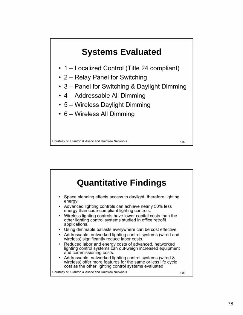
Systems Evaluated
• 1 – Localized Control (Title 24 compliant)• 2 – Relay Panel for Switching • 3 – Panel for Switching & Daylight Dimming• 4 – Addressable All Dimming • 5 – Wireless Daylight Dimming • 6 – Wireless All Dimming
Courtesy of Clanton & Assoc and Daintree Networks
156
Quantitative Findings• Space planning effects access to daylight, therefore lighting
energy. • Advanced lighting controls can achieve nearly 50% less
energy than code-compliant lighting controls. • Wireless lighting controls have lower capital costs than the
other lighting control systems studied in office retrofit applications.
• Using dimmable ballasts everywhere can be cost effective. • Addressable, networked lighting control systems (wired and
wireless) significantly reduce labor costs. • Reduced labor and energy costs of advanced, networked
lighting control systems can out-weigh increased equipment and commissioning costs.
• Addressable, networked lighting control systems (wired & wireless) offer more features for the same or less life cycle cost as the other lighting control systems evaluated
Courtesy of Clanton & Assoc and Daintree Networks

79
157
Qualitative Findings• Employee satisfaction is likely to increase with their ability to
control their lighting to provide the optimal luminous environment.
• Addressable, networked lighting systems allow for easy system reconfiguration, allowing the system to be adapted for future uses with minimal time and cost.
• Addressable, networked lighting systems are adaptable to changing room conditions, allowing sensor locations to be adjusted based on interior configurations.
• Real-time energy monitoring is possible through addressable, networked lighting systems (wired & wireless), allowing the operator of a building to understand the interaction of the users with the lighting system, provide education about the capabilities of the lighting system and personal energy use, and encourage education and awareness of lighting energy use.
Courtesy of Clanton & Assoc and Daintree Networks
158
Relative Capital Cost
0
20
40
6080
100
120
140
160
180
Sys 1 Sys 2 Sys 3 Sys 4 Sys 5 Sys 6
Perc
ent
Courtesy of Clanton & Assoc and Daintree Networks
Title 24 RelayPanel
DimmerPanel
AddressAll Dim
WirelessAll Dim
WirelessDay Dim
80
159
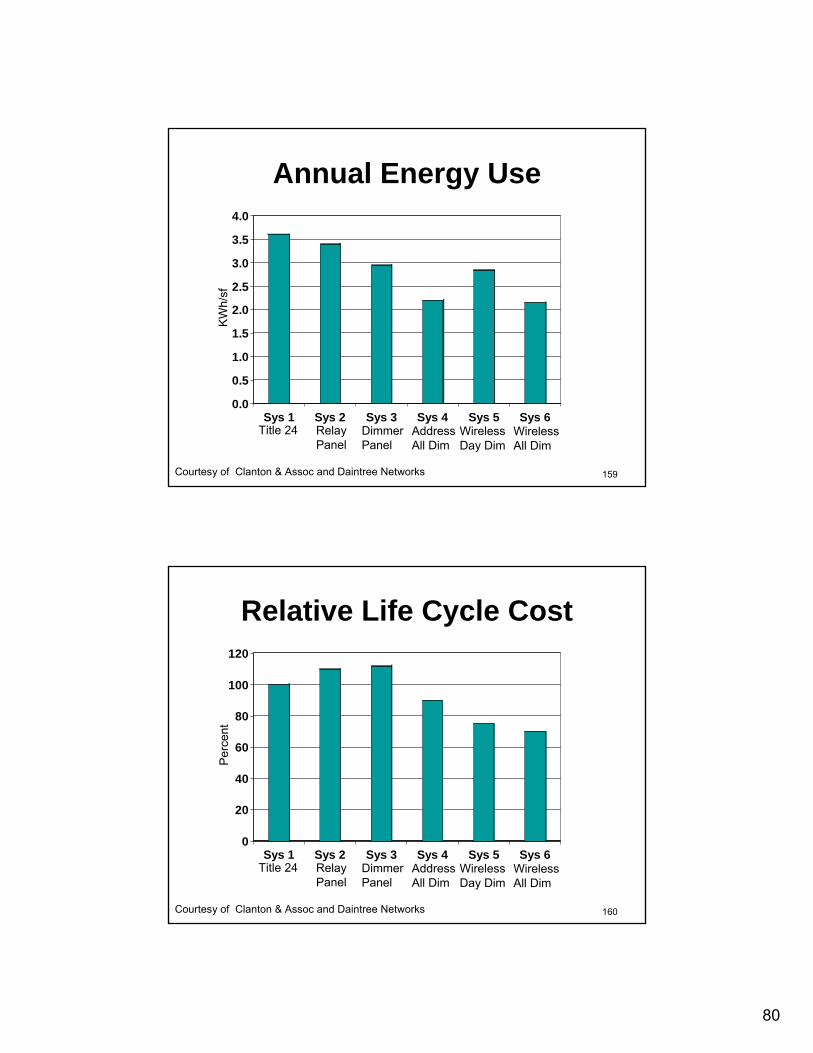
Annual Energy Use
0.0
0.5
1.0
1.5
2.0
2.5
3.0
3.5
4.0
Sys 1 Sys 2 Sys 3 Sys 4 Sys 5 Sys 6
KW
h/sf
Courtesy of Clanton & Assoc and Daintree Networks
Title 24 RelayPanel
DimmerPanel
AddressAll Dim
WirelessAll Dim
WirelessDay Dim
160
Relative Life Cycle Cost
0
20
40
60
80
100
120
Sys 1 Sys 2 Sys 3 Sys 4 Sys 5 Sys 6
Perc
ent
Courtesy of Clanton & Assoc and Daintree Networks
Title 24 RelayPanel
DimmerPanel
AddressAll Dim
WirelessAll Dim
WirelessDay Dim

81
161
Incentives
162
Announced May 3, 2011
82
163
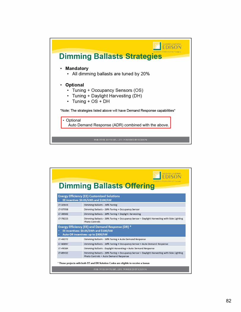
• OptionalAuto Demand Response (ADR) combined with the above.
164

83
165
166

84
167
How to Convey the Control System Design
168
Specifications• AIA, CSI, MasterSpec• Intent (Narrative,
Sequence of Operation)• Submittals• Warranties• Responsibilities• Deliverables
– As-Built drawings– Manuals– Training– Spare parts– Special tools
• Components• Systems• Integration with other
systems (AV, BMS, Etc)• Commissioning process
– Paperwork– Installation Verification– Start Up (by manufacturer)– Scene (dimmer) setting by
Lighting Designer– Acceptance Testing per
Title 24– Cx oversight by Third party

85
169
Specifications: CSI FormatSECTION 260000 - TITLE OF SPEC SECTIONPART 1 - GENERAL
1.1 Related Documents1.2 Summary1.3 Submittals1.4 Quality Assurance1.5 Coordination
PART 2 - PRODUCTSPART 3 - EXECUTION
3.1 Installation3.2 Field Quality Control3.3 Commissioning3.4 Training
170
• 260500 COMMON WORK RESULTS FOR ELECTRICAL• 260519 ELECTRICAL POWER CONDUCTORS AND CABLES• 260523 CONTROL ELECTRICAL POWER CABLES UTP• 260533 RACEWAY AND BOXES FOR ELECTRICAL SYSTEMS• 260553 IDENTIFICATION FOR ELECTRICAL SYSTEMS
Specifications: Electrical

86
171
• 260500 COMMON WORK RESULTS FOR ELECTRICAL• 260519 ELECTRICAL POWER CONDUCTORS AND CABLES• 260523 CONTROL ELECTRICAL POWER CABLES UTP• 260533 RACEWAY AND BOXES FOR ELECTRICAL SYSTEMS• 260553 IDENTIFICATION FOR ELECTRICAL SYSTEMS• 260923 LIGHTING CONTROL DEVICES• 260933 CENTRAL DIMMING CONTROLS• 260936 MODULAR DIMMING CONTROLS• 260943 NETWORK LIGHTING CONTROLS• 262726 WIRING DEVICES• 263323 CENTRAL BATTERY EQUIPMENT• 265100 INTERIOR LIGHTING• 265561 THEATRICAL LIGHTING• 265600 EXTERIOR LIGHTING
Specifications: Electrical
172
Commissioning
• Who does the initial commissioning?– Contractor, employee, consultant, manufacturer?
• Post-sales support - maintenance– Who handles re-commissioning when changes are
required due to changes in the function of the space?– Who maintains the system?– How much does it cost?
• Commissioning & maintenance must be written into the specifications!

87
173
Narratives
• In specifications• On drawings (preferred)
174
Drawings
• Lighting Floor Plans• Diagrams• Schedules
88
175
Lighting Floor Plans
• Room Names and No.• Luminaire locations, ID• Identify egress lighting• Lighting branch circuits
– Normal– Emergency– Panel name and circuit number
176
Lighting Floor Plans
• Control components– Wallbox devices– Ceiling devices– Control stations– Cabinets

89
177
Lighting Floor Plans
• Zones of control– a/b switching– multi-zone dimming
• Daylighting zones– Sidelight primary– Sidelight secondary– Skylight
178
Lighting Floor Plans

90
179
Lighting Floor Plans
180
Lighting Floor Plans
91
181
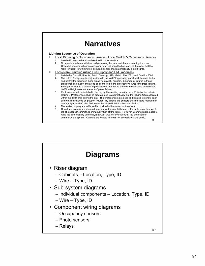
NarrativesLighting Sequence of OperationI. Local Dimming & Occupancy Sensors / Local Switch & Occupancy Sensors
1. Installed in areas other than described in other sections.2. Occupants shall manually turn on lights using the local switch upon entering the room.
Occupant sensors will sense occupancy and will keep the lights on. In the event that the room is vacant for 30 minutes, occupant sensor shall automatically turn off lights.
II. Ecosystem Dimming (using Bus Supply and BMJ modules)1. Installed at Stair #1, Stair #4, Public Queuing 1010, Main Lobby 1001, and Corridor 2001.2. The Lutron Ecosystem in conjunction with the WattStopper relay panel shall be used to dim
and control the lighting in these areas via daylight sensors. Emergency fixtures in these areas shall be on 24/7 and are to be connected to the emergency source for egress lighting. Emergency fixtures shall dim to preset levels after hours via the time clock and shall reset to 100% full brightness in the event of power failure.
3. Photosensors will be installed in the daylight harvesting area (i.e. with 15 feet of the exterior glazing). Photosensors shall be programmed to automatically dim the lighting fixtures located within the daylit area during the day. The photosensors are used and located to control each different lighting zone or group of fixtures. By default, the sensors shall be set to maintain an average light level of 15 to 20 footcandles at the Public Lobbies and Stairs.
4. The system is programmable and is provided with astronomic timeclock.5. Once the system is programmed, users have the capability to dim the lights lower than what
the photosensor commands or manually turn off the lights. However, users will not be able to raise the light intensity of the daylit harvest area nor override what the photosensorcommands the system. Controls are located in areas not accessible to the public.
182
Diagrams
• Riser diagram– Cabinets – Location, Type, ID– Wire – Type, ID
• Sub-system diagrams– Individual components – Location, Type, ID– Wire – Type, ID
• Component wiring diagrams– Occupancy sensors– Photo sensors– Relays

92
183
Riser Diagram
184
Riser Diagram

93
185
Sub-System Diagram
186
Daylight Harvesting Wiring

94
187
Component Wiring Diagrams
188
Schedules
• Relay panel schedules• Dimmer panel schedules• Override switch schedules• Daylight zone schedules• Shade control schedules• Component schedules • Time schedules

95
189
Schedule: Dimmer Panel
190
Schedule: Wallbox Dimmers
96
191
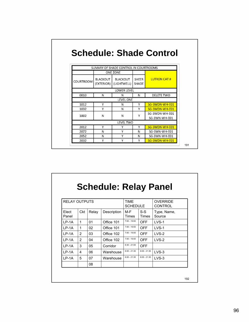
Schedule: Shade Control
192
Schedule: Relay PanelRELAY OUTPUTS TIME
SCHEDULEOVERRIDE CONTROL
Elect Panel
Ckt Relay Description M-F Times
S-S Times
Type, Name, Source
LP-1A 1 01 Office 101 7:00 - 19:00 OFF LVS-1LP-1A 1 02 Office 101 7:00 - 19:00 OFF LVS-1LP-1A 2 03 Office 102 7:00 - 19:00 OFF LVS-2
LP-1A 2 04 Office 102 7:00 - 19:00 OFF LVS-2
LP-1A 3 05 Corridor 6:30 - 21:00 OFF
LP-1A 4 06 Warehouse 6:00 - 21:30 6:00 - 21:30 LVS-3
LP-1A 5 07 Warehouse 6:00 - 21:30 6:00 - 21:30 LVS-3
08

97
193
Conclusion
• From Concept • To Construction
194
References• Clanton & Associates: “A Life Cycle Cost
Evalution of Multiple Lighting Control Strategies”• IES Seminar: Lighting Controls for
Nonresidential Buildings• LCA: Education Express:
http://www.aboutlightingcontrols.org/Education_Express/welcome.php
• NBI• NEMA• DOE

98
195
Credits• Acuity Brands• Adura Technologies• Clanton & Associates, Inc.• Benjamin• DALI• Douglas• Daintree Networks• Eaton/CH• EnOcean• Enovity• EMerge Alliance • ETC• Functional Devices• General Electric
• HOK• ILC • Illumra• LC&D• Leviton• Lumenergi• Lutron• Redwood Systems• Southern California Edison • Siemens• Square D• Sylvania • Tyco Electronics • Watt Stopper
196
THE END