advanced ipv6 deployment and services · 10.10.2010 · why cisco ios ipv6 vpn provider edge...
TRANSCRIPT

BRKRST-3305
Advanced IPv6 Deployment & Services
© 2010 Cisco and/or its affiliates. All rights reserved. Cisco PublicBRKRST-3305 2
Prerequisites: Session Abstract
This session will cover how an ISP can deploy IPv6, how an ISP provide IPv6 connectivity to its customers while still running IPv4. IPv6 service should be added to an existing IPv4 network without any interruption of V4 services. We will look at current SP topologies and protocols and evaluate best methodologies for introducing IPv6. We will evaluate existing transition mechanisms in the context of existing v4 deployment scenarios. Finally we will discuss MPLS based networks pure IP network deployments, and in that context discuss different protocols when deploying dual stack. Session will cover OSPFv3, ISIS, BGP architectural consideration when deploying IPV6.
Attendee must have a solid foundation of IPv6 basics (addressing, routing), MPLS, IPv4 networks and provisioning
© 2010 Cisco and/or its affiliates. All rights reserved. Cisco PublicBRKRST-3305 3
Agenda
SP ArchitecturePure IP Networks
MPLS networks
Enterprise Architecture
Address Allocation in SP & Enterprise
Routing Deployment – IGP & BGP
Routing Protocols Co-existence & Convergence

© 2010 Cisco and/or its affiliates. All rights reserved. Cisco PublicBRKRST-3305 4
SP ArchitecturePure IP Networks

© 2010 Cisco and/or its affiliates. All rights reserved. Cisco PublicBRKRST-3305 5
ISP Deployment Activities
Several Market segments
IX, Carriers, Regional ISP, Wireless
ISP have to get an IPv6 prefix from their Regional Registryhttp://www.arin.net
Large carriers are running trial networks but
Plans are largely driven by customer’s demand
Regional ISP focus on their specific markets
Japan is leading the worldwide deployment
Target is Home Networking services (dial, DSL, Cable, Ethernet-to-the-Home,…)
No easy Return on Investment (RoI) computation

© 2010 Cisco and/or its affiliates. All rights reserved. Cisco PublicBRKRST-3305 6
A Today’s Network Infrastructure
Service Providers core infrastructure are basically following 2 paths.
MPLS with its associated servicesMPLS/VPN, L2 services over MPLS, TE, QoS,…
Native IPv4 core with associated services
L2TPv3, QoS, Multicast,…
IP services portfolioEnterprise: Lease Lines
Home Users/SOHO: ADSL, ETTH, Dial
Data Center: Web hosting, servers,…
Next – The Integration of IPv6 services
© 2010 Cisco and/or its affiliates. All rights reserved. Cisco PublicBRKRST-3305 7
Service Provider networks
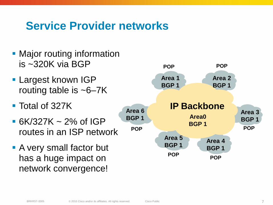
Major routing information is ~320K via BGP
Largest known IGProuting table is ~6–7K
Total of 327K
6K/327K ~ 2% of IGProutes in an ISP network
A very small factor but has a huge impact on network convergence!
IP Backbone
POP
POP POP
POP
Area 1BGP 1
POP POP
Area 6BGP 1
Area 5BGP 1
Area 4BGP 1
Area 2BGP 1
Area 3BGP 1Area0
BGP 1

© 2010 Cisco and/or its affiliates. All rights reserved. Cisco PublicBRKRST-3305 8
Access
RR WAN
Regional Core
PEPE PE
NMS
CE CE
IGP
You can reduce the IGP size to approx the number of exit routers in your network
This will bring really fast convergence
Optimized where you must and summarize where you can
Stops unnecessary flapping CE
Service Provider networkss

© 2010 Cisco and/or its affiliates. All rights reserved. Cisco PublicBRKRST-3305 9
Addressing
The link between PE-CE needs to be known for management purpose
BGP next-hop-self should be done on all access routers—unless PE-CE are on shared media (rare case)
This will cut down the size of the IGP
For PE-CE link do redistributed connected in BGP
These connected subnets should ONLY be sent through RR to NMS for management purpose; this can be done through BGP communities
Access
RR WAN
Regional Core
PEPE PE
NMS
CE CE
IGP
CE

© 2010 Cisco and/or its affiliates. All rights reserved. Cisco PublicBRKRST-3305 10
Addressing
Divide the address into two parts
1. Physical links
2. Loopback interfaces
Physical address should be in a contagious block
Loopback should be from public address space
Optimal path to the next hop is necessary
Access
RR WAN
Regional Core
PEPE PE
NMS
CE CE
IGP
CE
© 2010 Cisco and/or its affiliates. All rights reserved. Cisco PublicBRKRST-3305 11
Addressing
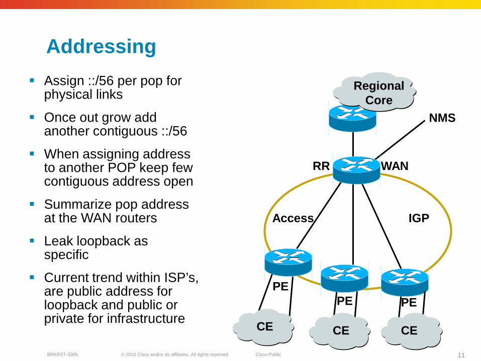
Assign ::/56 per pop for physical links
Once out grow add another contiguous ::/56
When assigning address to another POP keep few contiguous address open
Summarize pop address at the WAN routers
Leak loopback as specific
Current trend within ISP’s, are public address for loopback and public or private for infrastructure
Access
RR WAN
Regional Core
PEPE PE
NMS
CE CE
IGP
CE

© 2010 Cisco and/or its affiliates. All rights reserved. Cisco PublicBRKRST-3305 12
SP ArchitectureMPLS Networkers

© 2010 Cisco and/or its affiliates. All rights reserved. Cisco PublicBRKRST-3305 13
IPv6 over MPLS
Many service providers have already deployed MPLS in their IPv4 backbone for various reasons
MPLS can be used to facilitate IPv6 integration
Multiple approaches for IPv6 over MPLS:IPv6 over L2TPv3
IPv6 over EoMPLS/AToMIPv6 CE-to-CE IPv6 over IPv4 Tunnels
IPv6 Provider Edge Router (6PE) over MPLS
IPv6 VPN Provider Edge (6VPE) over MPLSNative IPv6 over MPLS

© 2010 Cisco and/or its affiliates. All rights reserved. Cisco PublicBRKRST-3305 14
P
P
P
Pv6
IPv4MPLSv4
v6
v4
v4
v6
v6
CE
CE
6PE
6PE 6PE
6PE
192.254.10.0
2001:0421::
2001:0420::
192.76.10.0
145.95.0.0
2001:0621::
2001:0620::
Dual-Stack IPv4-IPv6 RoutersDual-Stack IPv4-IPv6 Routers
CE
IPv6 Provider Edge Router (6PE) over MPLS
IPv4 or MPLS core infrastructure is IPv6-unaware PEs are updated to support dual stack/6PE IPv6 reachability exchanged among 6PEs via iBGP (MBGP) IPv6 packets transported from 6PE to 6PE inside MPLS
http://www.cisco.com/warp/public/cc/pd/iosw/prodlit/iosip_an.htm
iBGP (MBGP) Sessions

© 2010 Cisco and/or its affiliates. All rights reserved. Cisco PublicBRKRST-3305 15
6PE Routing/Label Distribution
6PE-2
6PE-1
P1 P2
2003:1::
2001:0db8::
10.10.20.1
10.10.20.2
IGPv4 Advertises Reachability of 10.10.20.1
IGPv6 or MP-BGP Advertising
2003:1::
IGP or MP-BGP Advertising
2003:1::
6PE-2 Sends MP-iBGP Advertisement to 6PE-1 which Says:2003:1:: is reachable via BGP Next Hop = 10.10.20.1 (6PE-2)bind BGP label to 2003:1:: (*)IPv6 Next Hop is an IPv4 mapped IPv6 address built from 10.10.20.1
LDPv4 Binds Label to
10.10.20.1
LDPv4 Binds Label to
10.10.20.1

© 2010 Cisco and/or its affiliates. All rights reserved. Cisco PublicBRKRST-3305 16
6PE Configuration
ip cefmpls label protocol ldptag-switching tdp router-id loopback0!interface Serial2/0ip address 10.10.10.2 255.255.255.252ip router isis mpls label protocol ldptag-switching ip!
ipv6 cefmpls label protocol ldpmpls ldp router-id loopback0!interface Loopback0ip address 10.10.20.2 255.255.255.255ipv6 address 2003::/64 eui-64!router bgp 100no synchronizationno bgp default ipv4-unicastbgp log-neighbor-changesneighbor 10.10.20.1 remote-as 100neighbor 10.10.20.1 update-source Loopback0!address-family ipv6neighbor 10.10.20.1 activateneighbor 10.10.20.1 send-labelredistribute connectedredistribute rip ripv6CE1exit-address-family!
StaticRIPngISISeBGP
CE6PE
P
Note: send-label will cause flap on peer

© 2010 Cisco and/or its affiliates. All rights reserved. Cisco PublicBRKRST-3305 17
Why Cisco IOS IPv6 VPN Provider Edge (6VPE)?
For VPN customers, IPv6 VPN service is exactly the same as IPv4 VPN service
Current 6PE is “like VPN” but this is NOT VPN, i.e., global reachability
For ISP offering MPLS/VPN for IPv4 that wish to add IPv6 services as well
No modification on the MPLS core
Support both IPv4 and IPv6 VPNs concurrently on the same interfacesConfiguration and operations of IPv6 VPNs exactly like IPv4 VPNs
© 2010 Cisco and/or its affiliates. All rights reserved. Cisco PublicBRKRST-3305 18
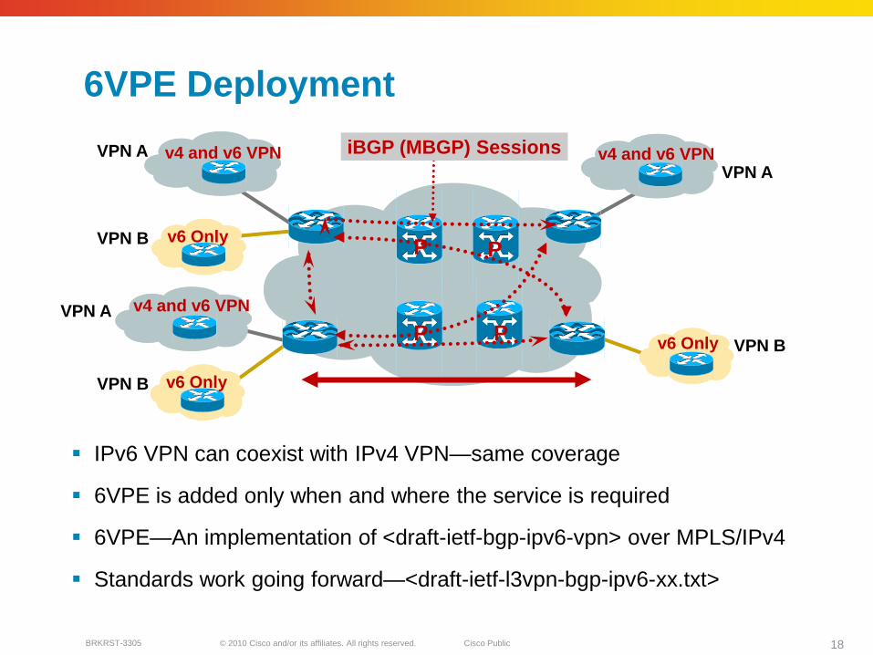
6VPE Deployment
IPv6 VPN can coexist with IPv4 VPN—same coverage
6VPE is added only when and where the service is required
6VPE—An implementation of <draft-ietf-bgp-ipv6-vpn> over MPLS/IPv4
Standards work going forward—<draft-ietf-l3vpn-bgp-ipv6-xx.txt>
P
P
P
P
iBGP (MBGP) Sessions
VPN B
VPN B
VPN A
v4 and v6 VPNVPN A
v6 Only
v6 Only
v4 and v6 VPN
VPN B
VPN A
v6 Only
v4 and v6 VPN

© 2010 Cisco and/or its affiliates. All rights reserved. Cisco PublicBRKRST-3305 19
6VPE Configuration Example
Site-1 Site-2 Site-3 Site-4
PE1
PE2
PP
Multihop MP-iBGP
VRFfor site-1(100:1)
Site-1 routesSite-2 routes
VRFfor site-4(100:3)
Site-3 routesSite-4 routes
VRFfor site-2(100:2)
Site-1 routesSite-2 routesSite-3 routes
VRFfor site-3(100:2)
Site-2 routesSite-3 routesSite-4 routes
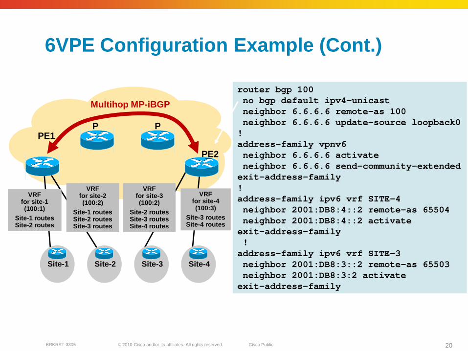
vrf definition SITE-3 rd 100:2address-family ipv6route-target export 100:2route-target import 100:2route-target import 100:3route-target export 100:3
!vrf definition SITE-4 rd 100:3address-family ipv6route-target export 100:3route-target import 100:3
!interface Serial4/6vrf forwarding SITE-3ipv6 address 2001:DB8:3::1/64!interface Serial4/7vrf forwarding SITE-4ipv6 address 2001:DB8:4::1/64
© 2010 Cisco and/or its affiliates. All rights reserved. Cisco PublicBRKRST-3305 20
router bgp 100no bgp default ipv4-unicastneighbor 6.6.6.6 remote-as 100neighbor 6.6.6.6 update-source loopback0!address-family vpnv6neighbor 6.6.6.6 activateneighbor 6.6.6.6 send-community-extendedexit-address-family!address-family ipv6 vrf SITE-4neighbor 2001:DB8:4::2 remote-as 65504neighbor 2001:DB8:4::2 activateexit-address-family!address-family ipv6 vrf SITE-3neighbor 2001:DB8:3::2 remote-as 65503neighbor 2001:DB8:3:2 activateexit-address-family
6VPE Configuration Example (Cont.)
Site-1 Site-2 Site-3 Site-4
PE1
PE2
PP
Multihop MP-iBGP
VRFfor site-1(100:1)
Site-1 routesSite-2 routes
VRFfor site-4(100:3)
Site-3 routesSite-4 routes
VRFfor site-2(100:2)
Site-1 routesSite-2 routesSite-3 routes
VRFfor site-3(100:2)
Site-2 routesSite-3 routesSite-4 routes
© 2010 Cisco and/or its affiliates. All rights reserved. Cisco PublicBRKRST-3305 21
Enterprise Architecture

© 2010 Cisco and/or its affiliates. All rights reserved. Cisco PublicBRKRST-3305 22
IPv6 Coexistence
IPv6 Network
IPv6 Network
IPv6 Host
Configured Tunnel/MPLS (6PE/6VPE)
IPv6 Host
MPLS/IPv4
IPv4: 192.168.99.1
IPv6: 2001:db8:1::1/64IPv6/IPv4
Dual Stack
IPv6ISATAPRouter
IPv4 ISATAP Tunneling(Intra-Site Automatic Tunnel Addressing Protocol)
Configured Tunnel/MPLS (6PE/6VPE)
© 2010 Cisco and/or its affiliates. All rights reserved. Cisco PublicBRKRST-3305 23
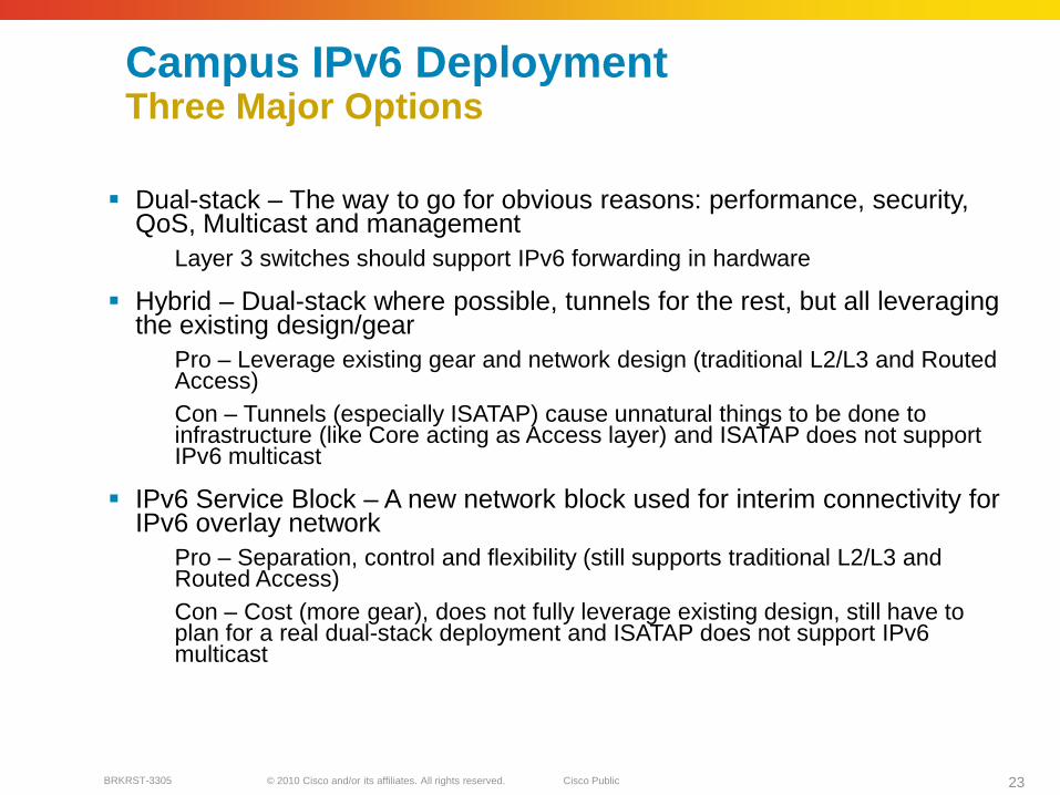
Campus IPv6 DeploymentThree Major Options
Dual-stack – The way to go for obvious reasons: performance, security, QoS, Multicast and management
Layer 3 switches should support IPv6 forwarding in hardware
Hybrid – Dual-stack where possible, tunnels for the rest, but all leveraging the existing design/gear
Pro – Leverage existing gear and network design (traditional L2/L3 and Routed Access) Con – Tunnels (especially ISATAP) cause unnatural things to be done to infrastructure (like Core acting as Access layer) and ISATAP does not support IPv6 multicast
IPv6 Service Block – A new network block used for interim connectivity for IPv6 overlay network
Pro – Separation, control and flexibility (still supports traditional L2/L3 and Routed Access)Con – Cost (more gear), does not fully leverage existing design, still have to plan for a real dual-stack deployment and ISATAP does not support IPv6multicast
© 2010 Cisco and/or its affiliates. All rights reserved. Cisco PublicBRKRST-3305 24
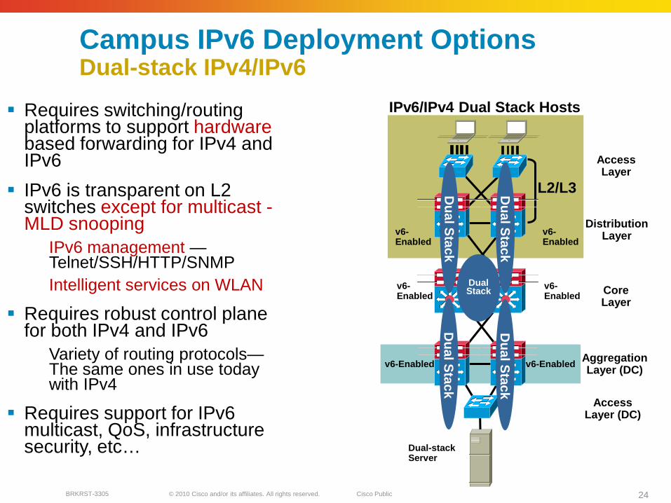
Campus IPv6 Deployment OptionsDual-stack IPv4/IPv6
Requires switching/routing platforms to support hardwarebased forwarding for IPv4 and IPv6
IPv6 is transparent on L2 switches except for multicast -MLD snooping
IPv6 management —Telnet/SSH/HTTP/SNMPIntelligent services on WLAN
Requires robust control plane for both IPv4 and IPv6
Variety of routing protocols—The same ones in use today with IPv4
Requires support for IPv6 multicast, QoS, infrastructure security, etc…
DistributionLayer
AccessLayer
CoreLayer
AggregationLayer (DC)
Dual-stackServer
L2/L3
v6-Enabled
v6-Enabled
v6-Enabled
v6-Enabled
IPv6/IPv4 Dual Stack Hosts
AccessLayer (DC)
DualStack
Du
al Stack
Du
al Stack
Du
al Stack
Du
al Stack
v6-Enabled
v6-Enabled

© 2010 Cisco and/or its affiliates. All rights reserved. Cisco PublicBRKRST-3305 25
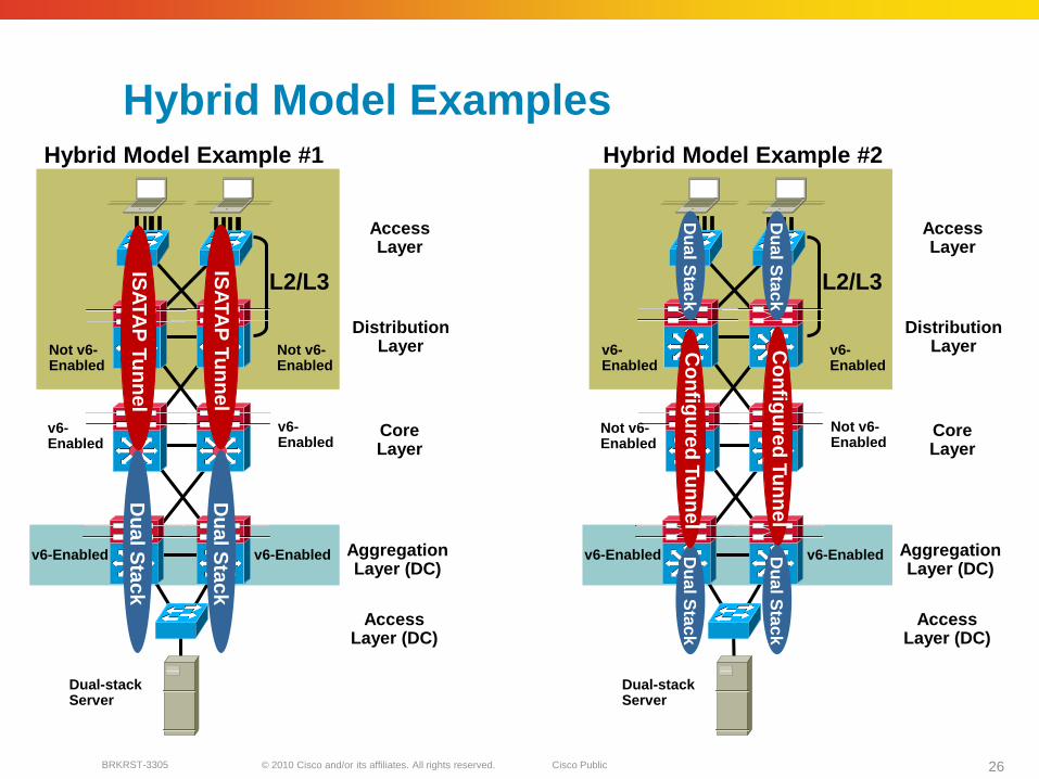
Campus IPv6 Deployment OptionsHybrid Model
Offers IPv6 connectivity via multiple options
Dual-stackConfigured tunnels – L3-to-L3ISATAP – Host-to-L3
Leverages existing network
Offers natural progression to full dual-stack design
May require tunneling to less-than-optimal layers (i.e. Core layer)
ISATAP creates a flat network (all hosts on same tunnel are peers)
Create tunnels per VLAN/subnet to keep same segregation as existing design (not clean today)
Provides basic HA of ISATAP tunnels via old Anycast-RP idea
ISATAP does not support IPv6 Multicast
Configured tunnels do support IPv6 Multicast
Dual-stackServer
L2/L3
v6-Enabled
Not v6-Enabled
v6-Enabled
Not v6-Enabled
v6-Enabled
v6-Enabled
Hybrid Model
DistributionLayer
AccessLayer
CoreLayer
AggregationLayer (DC)
AccessLayer (DC)
Du
al Stack
ISA
TAP
Tun
nel
Du
al Stack
ISA
TAP
Tun
nel
© 2010 Cisco and/or its affiliates. All rights reserved. Cisco PublicBRKRST-3305 26
Hybrid Model ExamplesHybrid Model Example #2
Dual-stackServer
L2/L3
v6-Enabled
Not v6-Enabled
v6-Enabled
Not v6-Enabled
v6-Enabled
v6-Enabled
Hybrid Model Example #1
DistributionLayer
AccessLayer
CoreLayer
AggregationLayer (DC)
AccessLayer (DC)
Du
al Stack
ISA
TAP
Tun
nel
Du
al Stack
ISA
TAP
Tun
nel
Dual-stackServer
L2/L3
v6-Enabled
v6-Enabled
v6-Enabled
v6-Enabled
Not v6-Enabled
Not v6-Enabled
DistributionLayer
AccessLayer
CoreLayer
AggregationLayer (DC)
AccessLayer (DC)
Co
nfig
ured
Tun
nel
Du
al Stack
Du
al Stack
Co
nfig
ured
Tun
nel
Du
al Stack
Du
al Stack

© 2010 Cisco and/or its affiliates. All rights reserved. Cisco PublicBRKRST-3305 27
Highly Available ISATAP DesignTopology
ISATAP tunnels from PCs in Access layer to Core switches
Redundant tunnels to Core or Service block
Use IGP to prefer one Core switch over another (both v4 and v6 routes) - deterministic
Preference is important due to the requirement to have traffic (IPv4/IPv6) route to the same interface (tunnel) where host is terminated on - Windows XP/2003
In this example dual-stack is used from Data Center to Core
IPv6 Server
v6-Enabled v6-Enabled
Not v6-Enabled
v6-Enabled
v6-Enabled
DistributionLayer
AccessLayer
CoreLayer
AggregationLayer (DC)
AccessLayer (DC)
Du
al Stack
PC1 - Red VLAN 2 PC2 - Blue VLAN 3
Not v6-Enabled
Du
al Stack
Primary ISATAP Tunnel
Secondary ISATAP Tunnel

© 2010 Cisco and/or its affiliates. All rights reserved. Cisco PublicBRKRST-3305 28
IPv6 Campus ISATAP ConfigurationISATAP Client Configuration
C:\>netsh int ipv6 isatap set router 10.122.10.103
Ok.
int lo310.122.10.103
int tu3
int lo310.122.10.103
10.120.3.101
int tu3
Tunnel adapter Automatic Tunneling Pseudo-Interface:
Connection-specific DNS Suffix . :
IP Address. . . . . . . . . . . . : 2001:db8:cafe:3:0:5efe:10.120.3.101
IP Address. . . . . . . . . . . . : fe80::5efe:10.120.3.101%2
Default Gateway . . . . . . . . . : fe80::5efe:10.122.10.103%2
interface Tunnel3
ipv6 address 2001:DB8:CAFE:3::/64 eui-64
no ipv6 nd suppress-ra
ipv6 ospf 1 area 2
tunnel source Loopback3
tunnel mode ipv6ip isatap
!
interface Loopback3
description Tunnel source for ISATAP-VLAN3
ip address 10.122.10.103 255.255.255.255
New tunnel comes up
when failure occurs
Windows XP/Vista Host

© 2010 Cisco and/or its affiliates. All rights reserved. Cisco PublicBRKRST-3305 29
Campus IPv6 Deployment OptionsIPv6 Service Block – An Interim Approach
Provides ability to rapidly deploy IPv6 services without touching existing network
Provides tight control of where IPv6 is deployed and where the traffic flows (maintain separation of groups/locations)
Offers the same advantages as Hybrid Model without the alteration to existing code/configurations
Configurations are very similar to the Hybrid Model
ISATAP tunnels from PCs in Access layer to Service Block switches (instead of core layer – Hybrid)
1) Leverage existing ISP block for both IPv4 and IPv6 access
2) Use dedicated ISP connection just for IPv6 – Can use IOS FW or PIX/ASA appliance
ISATAP
IPv6 Service Block
Intern
et
Dedicated FW
IOS FW
Data Center Block
VLAN 2
WAN/ISP Block
Primary ISATAP Tunnel
Secondary ISATAP Tunnel
Equal-cost Configured Tunnel (Mesh)
IPv4-onlyCampusBlock
AggLayer
VLAN 3
2
1
AccessLayer
DistributionLayer
CoreLayer

© 2010 Cisco and/or its affiliates. All rights reserved. Cisco PublicBRKRST-3305 30
Address AllocationsSP & Enterprise
© 2010 Cisco and/or its affiliates. All rights reserved. Cisco PublicBRKRST-3305 31
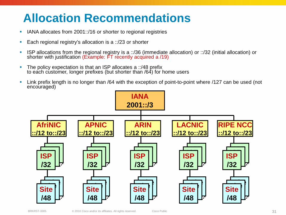
Allocation Recommendations IANA allocates from 2001::/16 or shorter to regional registries
Each regional registry’s allocation is a ::/23 or shorter
ISP allocations from the regional registry is a ::/36 (immediate allocation) or ::/32 (initial allocation) or shorter with justification (Example: FT recently acquired a /19)
The policy expectation is that an ISP allocates a ::/48 prefix to each customer, longer prefixes (but shorter than /64) for home users
Link prefix length is no longer than /64 with the exception of point-to-point where /127 can be used (not encouraged)
Site/48
Site/48
ISP/32
ISP/32
IANA2001::/3
APNIC::/12 to::/23
AfriNIC::/12 to::/23
ARIN::/12 to::/23
LACNIC::/12 to::/23
RIPE NCC::/12 to::/23
ISP/32
Site/48
Site/48
Site/48
ISP/32
ISP/32
ISP/32
Site/48
Site/48
Site/48
ISP/32
ISP/32
ISP/32
Site/48
Site/48
Site/48
ISP/32
ISP/32
ISP/32
Site/48
Site/48
Site/48
ISP/32
ISP/32
ISP/32
Site/48
© 2010 Cisco and/or its affiliates. All rights reserved. Cisco PublicBRKRST-3305 32
SP IPv6 Address Allocation SP addressing scheme
Usually SP get the address allocated by the local registry via IANA
The block is usually /32 but exception can be made for a bigger ISP
SP usually assign addresses for Consumers. There are 2 types:
Fixed allocation:
Cable customers, DSL customers, ETTH etc
Mobile allocation:
Mobile customers
© 2010 Cisco and/or its affiliates. All rights reserved. Cisco PublicBRKRST-3305 33
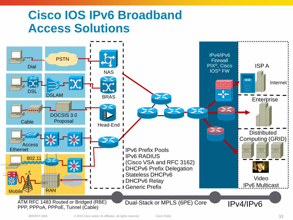
Cisco IOS IPv6 Broadband Access Solutions
VideoIPv6 Multicast
DistributedComputing (GRID)
Enterprise
Internet
ISP APSTN
Dial
DSLAMDSL
802.11
AccessEthernet
DOCSIS 3.0 ProposalCable
Mobile RAN
NAS
BRAS
Head-End
Layer 2 Encapsulation(s)
ATM RFC 1483 Routed or Bridged (RBE)PPP, PPPoA, PPPoE, Tunnel (Cable)
Dual-Stack or MPLS (6PE) Core IPv4/IPv6
IPv4/IPv6Firewall
PIX®, Cisco IOS® FW
IPv6 Prefix PoolsIPv6 RADIUS(Cisco VSA and RFC 3162)DHCPv6 Prefix DelegationStateless DHCPv6DHCPv6 RelayGeneric Prefix
SiSi

© 2010 Cisco and/or its affiliates. All rights reserved. Cisco PublicBRKRST-3305 34
IPv6 prefix-pools
Normal prefix pools: ipv6 prefix-pool foo 3ffe:c00:1::/48 64
A Separate /64 is assigned each user/interface. The prefix is advertised in RA’s and a route is installed in the RIB.
Shared prefix pools:ipv6 prefix-pool foo 3ffe:c00:2::/64 128 shared
/64 prefix is shared between all users of the pool. The same /64 prefix is advertised in RA’s out all interfaces. The user gets an /128 based on the prefix and his Interface-Identifier. A route in the RIB is installed only for the /128.
© 2010 Cisco and/or its affiliates. All rights reserved. Cisco PublicBRKRST3305 35
“…recommends the assignment of /48 in the general case, /64 when it is known that one and only one subnet is needed…”
RFC3177IAB/IESG Recommendations on IPv6 Address Allocations to Sites
IPv6 Address Allocation Guidelines

© 2010 Cisco and/or its affiliates. All rights reserved. Cisco PublicBRKRST-3305 36
Policy Implementation
Give Home/SOHO a permanent /64 – single link
Give Home/SOHO a permanent /48
Short-lived /64 from a prefix-poolA Separate /64 is assigned to each user/interface. The prefix is advertised in RA’s and a route is installed in the RIB.
Short-lived /128 from a shared prefix-pool/64 prefix is shared between all users of the pool. The same /64 prefix is advertised in RA’s out all interfaces. The user gets an /128 based on the prefix and his Interface-Identifier. A route in the RIB is installed only for the /128.
For some users set the Interface-ID explicitly
© 2010 Cisco and/or its affiliates. All rights reserved. Cisco PublicBRKRST-3305 37
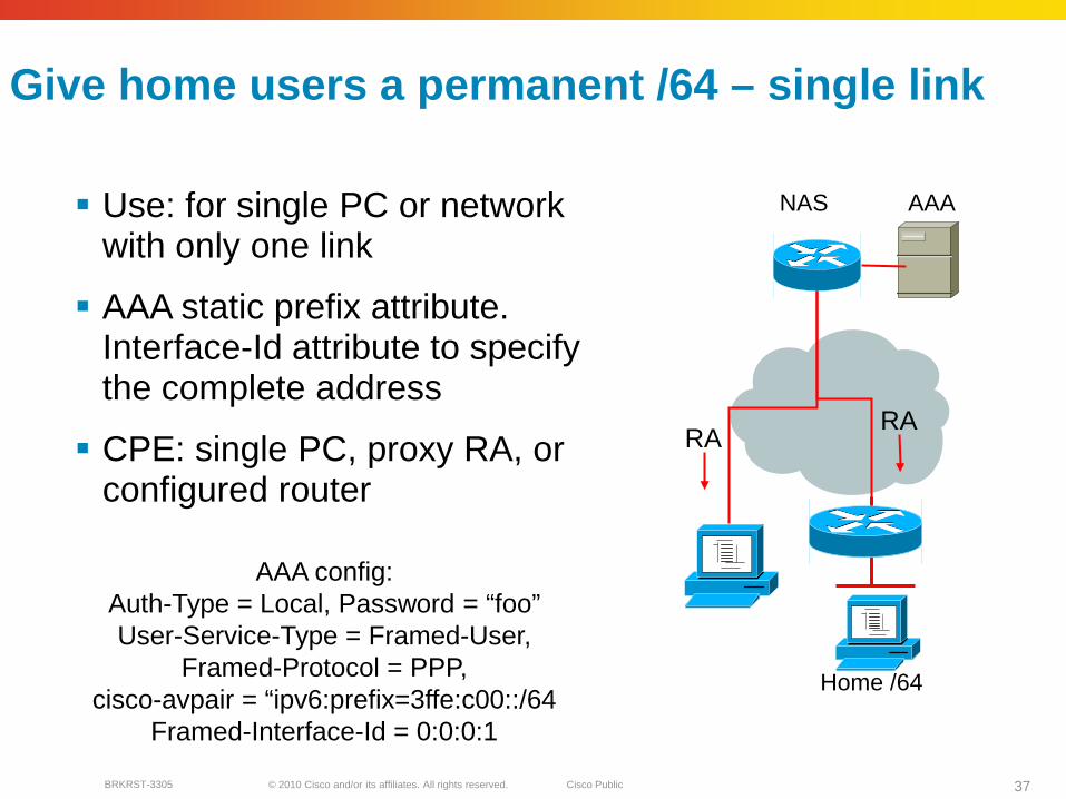
Give home users a permanent /64 – single link
Use: for single PC or network with only one link
AAA static prefix attribute. Interface-Id attribute to specify the complete address
CPE: single PC, proxy RA, or configured router
NAS
Home /64
AAA
RA
AAA config:Auth-Type = Local, Password = “foo”User-Service-Type = Framed-User,
Framed-Protocol = PPP,cisco-avpair = “ipv6:prefix=3ffe:c00::/64
Framed-Interface-Id = 0:0:0:1
RA

© 2010 Cisco and/or its affiliates. All rights reserved. Cisco PublicBRKRST-3305 38
Give home users a permanent /48
Use: whole site -supports multiple links
AAA prefix-attribute
Use DHCP-PD to configure the CPE
NAS AAA
Auth-Type = Local, Password = “foo2”User-Service-Type = Framed-User,
Framed-Protocol = PPP,cisco-avpair = “ipv6:prefix=3ffe:c00::/64
/64
/64
interface Atm 0pvc 1/23encapsulation aal5mux ppp dialer
dialer pool-member 1 !interface dialer1ipv6 dhcp client pd DH-PREFIX!interface FastEthernet0
ipv6 address DH-PREFIX 0:0:0:1::/64 eui-64!
DHCP
Fa0Fa1

© 2010 Cisco and/or its affiliates. All rights reserved. Cisco PublicBRKRST-3305 39
Address Assignment – short-lived /64
Use: for single PC or very simple network
NAS: IPv6 prefix pool
CPE: Proxy-RA/multi-link subnet/bridgingRenumbering issues
NAS
Home /64
AAA
AAA config:Auth-Type = Local, Password = “foo”User-Service-Type = Framed-User,
Framed-Protocol = PPP,cisco-avpair = “addr-pool=“foo”
RA

© 2010 Cisco and/or its affiliates. All rights reserved. Cisco PublicBRKRST-3305 40
Address Assignment – short-lived /128
Use: for single PC only. Allows one address
/64 prefix shared between all users of the pool
AAA interface-id attribute can be used to specify complete address
NAS: IPv6 shared prefix pools
CPE: Single PC
NAS AAA
RA
AAA config:Auth-Type = Local, Password = “foo”User-Service-Type = Framed-User,
Framed-Protocol = PPP,cisco-avpair = “addr-pool=“foo-shared”
© 2010 Cisco and/or its affiliates. All rights reserved. Cisco PublicBRKRST-3305 41
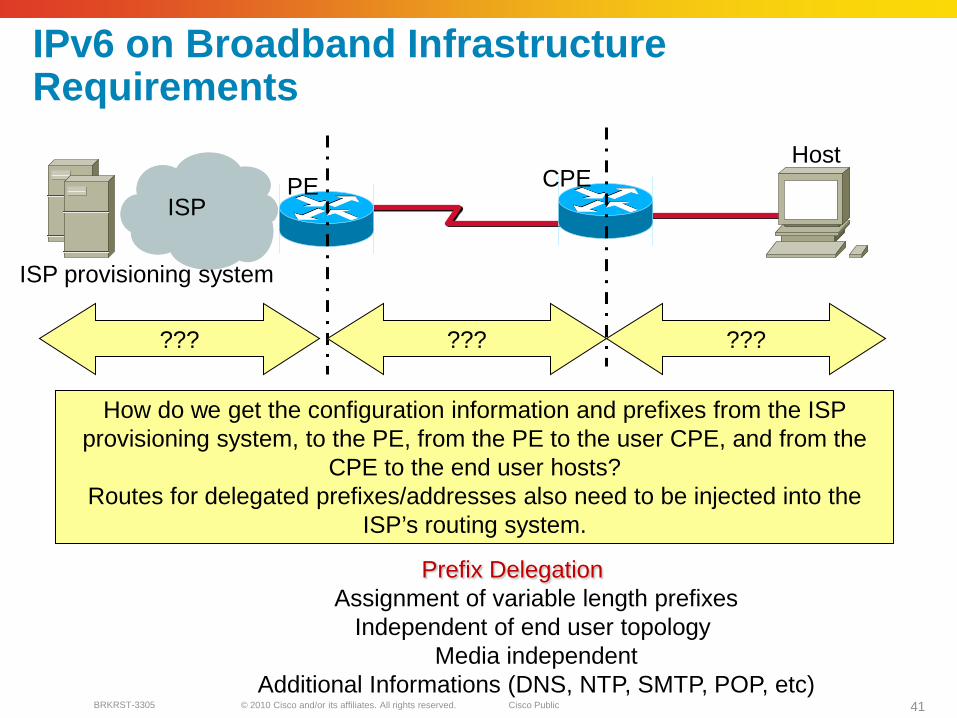
IPv6 on Broadband Infrastructure Requirements
CPEPEISP
Host
ISP provisioning system
How do we get the configuration information and prefixes from the ISP provisioning system, to the PE, from the PE to the user CPE, and from the
CPE to the end user hosts?Routes for delegated prefixes/addresses also need to be injected into the
ISP’s routing system.
??? ??????
Prefix DelegationAssignment of variable length prefixes
Independent of end user topology Media independent
Additional Informations (DNS, NTP, SMTP, POP, etc)

© 2010 Cisco and/or its affiliates. All rights reserved. Cisco PublicBRKRST-3305 42
Large Scale Deployment Suggested solution
CPEPEISP
Host
ISP provisioning system
The PE can also send RA’s on the PE-CPE link, and the CPE can auto-configure an “uplink” address. Prefix should be different from the prefix
assigned to the user.
DHCP ND/DHCPAAA
(3) CPE sends DHCP solicit,
with ORO = PD
(1) PE sends RADIUS request
for the user
(2) RADIUS responds with
user’s prefix(es)
(4) PE sends DHCP REPLY,
with Prefix Delegation
options
(5) CPE configures addresses from the prefix on its
downstream interfaces, and sends an RA. O-bit is set to on.
(6) Host configures addresses based on the prefixes received in the RA. As the O-
bit is on, it send a DHCP INFORMATION-REQUEST message,
with an ORO = DNS
(7) CPE sends a DHCP REPLY containing request options. Note that the
CPE is configured as a DHCP client upstream, and as a DHCP server
downstream. The DHCP downstream server acts as a cache, and uses the
options received on the upstream interface.

© 2010 Cisco and/or its affiliates. All rights reserved. Cisco PublicBRKRST-3305 43
Enterprise IPv6 Address Allocation
Enterprise addressing schemeGet you own address from local registry via IANA OR
Get it via Service Providers
Unique local address if the network does not need to go on the Internet
Usually get a block of /48 unless a justification for a larger block is made
PI address for multihoming

© 2010 Cisco and/or its affiliates. All rights reserved. Cisco PublicBRKRST-3305 44
Provider-Independent Addresses
Driven mainly by enterprises
Adopted (April 2006) because there is no consensus on Multihoming for IPv6 (NANOG rejected the IETF shim proposal)
The possible impact is still debated but it seems we will just have to deal with it. Lack of PI could however slow down IPv6 adoption.
BGP can only control routing table growth if routes are aggregated
Number of multi-homed sites increasing quickly (>10,000)
The IPv6 address space is very large
Routing table growth could be problematical with the capability of the current hardware and protocols
Provider Independent Proposal: http://www.arin.net/policy/proposals/2005_1.html
© 2010 Cisco and/or its affiliates. All rights reserved. Cisco PublicBRKRST-3305 45
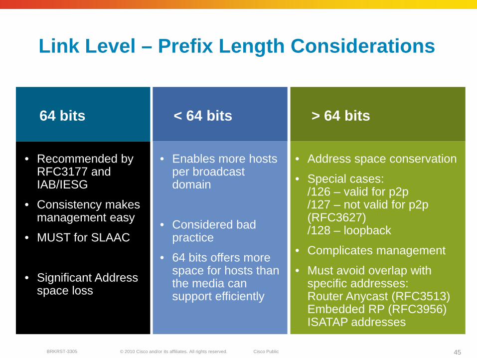
Link Level – Prefix Length Considerations
64 bits
• Recommended by RFC3177 and IAB/IESG
• Consistency makes management easy
• MUST for SLAAC
• Significant Address space loss
• Enables more hosts per broadcast domain
• Considered bad practice
• 64 bits offers more space for hosts than the media can support efficiently
< 64 bits > 64 bits
• Address space conservation
• Special cases:/126 – valid for p2p/127 – not valid for p2p (RFC3627)/128 – loopback
• Complicates management
• Must avoid overlap with specific addresses:Router Anycast (RFC3513)Embedded RP (RFC3956)ISATAP addresses
© 2010 Cisco and/or its affiliates. All rights reserved. Cisco PublicBRKRST-3305 46
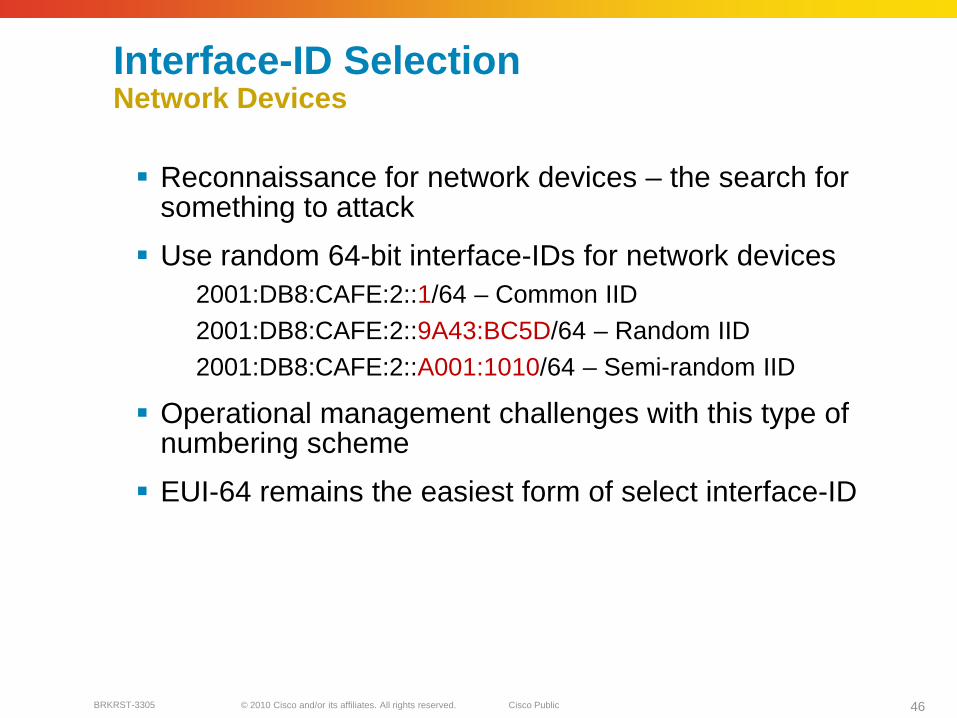
Interface-ID SelectionNetwork Devices
Reconnaissance for network devices – the search for something to attack
Use random 64-bit interface-IDs for network devices2001:DB8:CAFE:2::1/64 – Common IID2001:DB8:CAFE:2::9A43:BC5D/64 – Random IID2001:DB8:CAFE:2::A001:1010/64 – Semi-random IID
Operational management challenges with this type of numbering scheme
EUI-64 remains the easiest form of select interface-ID

© 2010 Cisco and/or its affiliates. All rights reserved. Cisco PublicBRKRST-3305 47
Routing DeploymentsIGP & BGP

© 2010 Cisco and/or its affiliates. All rights reserved. Cisco PublicBRKRST-3305 48
Routing in SP network Prefixes coming into the SP network could be:
SP’s owned pefixes assigned by the SP to the consumer
Enterprise owned prefixes from their allocated block
Options for SP to provide Transit servicesThe transit routing can be done via BGP as in IPv4
The MPLS based SP can provide 6PE & 6VPE services
Purist ProviderCable providers (usually no MPLS)
Tunnel at the edge using GRE, L2TP
6to4?

© 2010 Cisco and/or its affiliates. All rights reserved. Cisco PublicBRKRST-3305 49
IPv6 Challenges to Router Performance
Forwarding challenges—lookup not impacted as much as originally thought, different size prefixes typically see little difference in forwarding performance
Control plane challenges—routing table sizes:IPv6 supports multiple addresses per interface (not the most significant concern at this time but it could be in the future)
IPv6 can have a lot more prefixes due to a significantly larger address space
Addressing Driven

© 2010 Cisco and/or its affiliates. All rights reserved. Cisco PublicBRKRST-3305 50
The Questions Are the Same as for IPv4… Almost
Is one routing protocol better than any other routing protocol?
Define “Better”
Converges faster?
Uses less resources?
Easier to troubleshoot?
Easier to configure?
Scales to a larger number of routers, routes, or neighbors?
More flexible?
Degrades more gracefully?
And so on

© 2010 Cisco and/or its affiliates. All rights reserved. Cisco PublicBRKRST-3305 51
IPv6 IGP Selection—In Theory
The similarity between the IPv6 and IPv4 routing protocols leads to similar behavior and expectations
To select the IPv6 IGP, start by using the IPv4 IGP rules of thumb
In Theory:

© 2010 Cisco and/or its affiliates. All rights reserved. Cisco PublicBRKRST-3305 52
IPv6 IGP Selection—In Practice
In practice:The IPv6 IGP implementations might not be fully optimized yet so there is a bit more uncertainty
Not all knobs for Fast Convergence might be available
No significant operational experience with large scale IPv6 networks

© 2010 Cisco and/or its affiliates. All rights reserved. Cisco PublicBRKRST-3305 53
Conclusions
Same topology considerations as for IPv4
Convergence timeThere are HW and SW dependencies
The average convergence time is 100% larger than IPv4, as IPv6 converges after IPv4
Not all knobs are available. Ex: Fast Hellos for OSPFv3 -> Bidirectional Forwarding Detection (BFD) instead in the future.
Test tools still need to improve

© 2010 Cisco and/or its affiliates. All rights reserved. Cisco PublicBRKRST-3305 54
IGP deployment ALL IPv6 IGP runs over link local
addressing
Global Prefixes may not need to be assigned on the interface
This reduces the size of the routing table
SNMP can be used to manage the links
Router needs to have one IPv4 & one IPv6 loopback assigned.
SNMP polling can be done over IPv4 or IPv6.
Infrastructure security by reducing routes & using link-local
Core will act as a transit point.
This makes the network more scalable
Access
RR WAN
PEPE PE
NMS
CECE CE
BGP
Regional Core

© 2010 Cisco and/or its affiliates. All rights reserved. Cisco PublicBRKRST-3305 55
Routing DeploymentsISISv6

© 2010 Cisco and/or its affiliates. All rights reserved. Cisco PublicBRKRST-3305 56
Integrated IS-IS for IPv6—Overview
IETF draft: draft-ietf-isis-ipv6-06.txt
Two TLVs added to support IPv6: IPv6 Reachability TLV (0xEC)—Describes network reachability (IPv6 routing prefix, metric information and option bits). The option bits indicate the advertisement of IPv6 prefix from a higher level, redistribution from other routing protocols. Equivalent to IP Internal/External Reachability TLVs described in RFC1195.
IPv6 Interface Address TLV (0xE8)—Contains 128-bit address. Hello PDUs, must contain the link-local address but for LSP, must only contain the non-link-local address.
A new Network Layer Protocol Identifier (NLPID)—Allows IS-IS routers with IPv6 support to advertise IPv6 prefix payload using 0x8E value (IPv4 and OSI uses different values)

© 2010 Cisco and/or its affiliates. All rights reserved. Cisco PublicBRKRST-3305 57
Integrated IS-IS—IPv4 and IPv6
Single topology (default for all protocols supported). Potentially beneficial in saving resources (same topology and same SPF):
All routers must support the same address families (dual-stack, topologically congruent network). Adjacency checking should be disabled during migration.Interface metrics apply to both IPv4 and IPv6
Multi-topology (draft-ietf-isis-wg-multi-topology)Independent IPv4 and IPv6 topologiesIndependent interface metrics
Transition mode available—both types of TLVs are advertised

© 2010 Cisco and/or its affiliates. All rights reserved. Cisco PublicBRKRST-3305 58
Router1#show clns is-neighbors detailSystem Id Interface State Type Priority Circuit Id FormatRouter2 Fa0/1 Up L1L2 64/64 Router2.01 Phase VArea Address(es): 49.0001IP Address(es): 10.7.1.34*IPv6 Address(es): FE80::2B0:4AFF:FE5C:ACA9Uptime: 00:01:25NSF capable
Area 49.0001
IS-IS Single Topology Example
FE0/1 2001:db8:ffff::1/6410.7.1.33
E0 2001:db8:ffff::2/64FE80::2B0:4AFF:FE5C:ACA910.7.1.34
Router1#show isis database verbose level-1IS-IS Level-1 Link State Database:LSPID LSP Seq Num LSP Checksum LSP Holdtime ATT/P/OLRouter2.00-00 0x0000000B 0xAB35 1020 0/0/0
Area Address: 49.0001NLPID: 0xCC 0x8EHostname: Router2IP Address: 10.7.1.34Metric: 10 IP 10.7.1.32 255.255.255.252IPv6 Address: 2001:db8:FFFF::2Metric: 10 IPv6 2001:db8:FFFF::/64Metric: 10 IS Router2.01
router isis example-areanet 49.0001.0000.0000.0001.00
!interface FastEthernet0/1ip address 10.7.1.33 255.255.255.252ip router isis example-areaipv6 address 2001:db8:FFFF::1/64ipv6 enableipv6 router isis example-area
Router1

© 2010 Cisco and/or its affiliates. All rights reserved. Cisco PublicBRKRST-3305 59
Router1#show clns is-neighbors detailSystem Id Interface State Type Priority Circuit Id FormatRouter2 Fa0/1 Up L1L2 64/64 Router2.01 Phase VArea Address(es): 49.0001IP Address(es): 10.7.1.34*IPv6 Address(es): FE80::2B0:4AFF:FE5C:ACA9Uptime: 00:00:14NSF capableTopology: IPv4, IPv6
IS-IS Multi Topology ExampleRouter1#show isis database verbose level-1IS-IS Level-1 Link State Database:LSPID LSP Seq Num LSP Checksum LSP Holdtime ATT/P/OLRouter2.00-00 0x00000014 0x8B3E 1086 0/0/0Area Address: 49.0001Topology: IPv4 (0x0) IPv6 (0x2)NLPID: 0xCC 0x8EHostname: Router2IP Address: 10.7.1.34Metric: 10 IP 10.7.1.32/30IPv6 Address: 2001:db8:FFFF::2Metric: 10 IPv6 (MT-IPv6) 2001:db8:FFFF::/64Metric: 10 IS (MT-IPv6) Router2.01
Area 49.0001
FE0/1 2001:db8:ffff::1/6410.7.1.33
E0 2001:db8:ffff::2/64FE80::2B0:4AFF:FE5C:ACA910.7.1.34
Router1
router isis example-areanet 49.0001.0000.0000.0001.00metric-style wide transition!address-family ipv6multi-topology transition

© 2010 Cisco and/or its affiliates. All rights reserved. Cisco PublicBRKRST-3305 60
Routing DeploymentsOSPFv3
© 2010 Cisco and/or its affiliates. All rights reserved. Cisco PublicBRKRST-3305 61
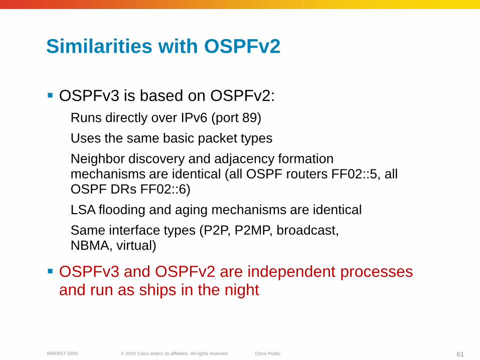
Similarities with OSPFv2
OSPFv3 is based on OSPFv2:Runs directly over IPv6 (port 89)
Uses the same basic packet types
Neighbor discovery and adjacency formation mechanisms are identical (all OSPF routers FF02::5, all OSPF DRs FF02::6)
LSA flooding and aging mechanisms are identical
Same interface types (P2P, P2MP, broadcast, NBMA, virtual)
OSPFv3 and OSPFv2 are independent processes and run as ships in the night

© 2010 Cisco and/or its affiliates. All rights reserved. Cisco PublicBRKRST-3305 62
V2, V3 Differences
A link by definition is a medium over which two nodes can communicate at link layer
Regardless of assigned prefixes, two devices can communicate using link-local addresses therefore OSPFv3 is running per link instead of per IP prefix
Multiple IPv6 prefixes can be assigned to the same link
OSPFv3 Is Running per Link Instead of per Node (and IP Subnet)

© 2010 Cisco and/or its affiliates. All rights reserved. Cisco PublicBRKRST-3305 63
V2, V3 Differences (Cont.)
New field (instance) in OSPF packet header allows running multiple instances per link
Instance ID should match before packet is being accepted
Useful for traffic separation, multiple areas per link
Support of Multiple Instances per Link

© 2010 Cisco and/or its affiliates. All rights reserved. Cisco PublicBRKRST-3305 64
V2, V3 Differences (Cont.)
Router and network LSA carry only topology information
Router LSA can be split across multiple LSAs; link state ID in LSA header is a fragment ID
Intra-area prefixes are carried in a new LSA payload called intra-area-prefix-LSAs
Prefixes are carried in the payload of inter-area and external LSA
Address Semantic Changes in LSA

© 2010 Cisco and/or its affiliates. All rights reserved. Cisco PublicBRKRST-3305 65
V2, V3 Differences (Cont.)
In OSPFv3 there are three flooding scopes for LSAs (link-local scope, area scope, AS scope) and they are coded in the LS type explicitly
In OSPFv2 initially only area and AS wide flooding was defined; later opaque LSAs introduced link local scope, as well
Generalization of Flooding Scope
© 2010 Cisco and/or its affiliates. All rights reserved. Cisco PublicBRKRST-3305 66
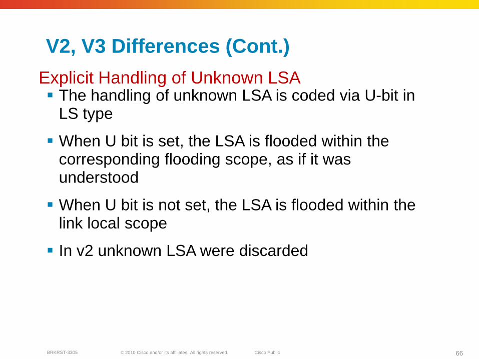
V2, V3 Differences (Cont.)
The handling of unknown LSA is coded via U-bit in LS type
When U bit is set, the LSA is flooded within the corresponding flooding scope, as if it was understood
When U bit is not set, the LSA is flooded within the link local scope
In v2 unknown LSA were discarded
Explicit Handling of Unknown LSA

© 2010 Cisco and/or its affiliates. All rights reserved. Cisco PublicBRKRST-3305 67
V2, V3 Differences (Cont.)
Authentication in OSPFv3 has been removed and OSPFv3 relies now on IPv6 authentication header since OSPFv3 runs over IPv6
Autype and authentication field in the OSPF packet header therefore have been suppressed
Authentication Is Removed from OSPF

© 2010 Cisco and/or its affiliates. All rights reserved. Cisco PublicBRKRST-3305 68
V2, V3 Differences (Cont.)
The mask field has been removed from hello packet
IPv6 prefix are only present in payload of link state update packet
OSPF Packet Format Has Been Changed

© 2010 Cisco and/or its affiliates. All rights reserved. Cisco PublicBRKRST-3305 69
V2, V3 Differences (Cont.)
Link-LSA has a link local flooding scope and has three purposes
Carry IPv6 link local address used for NH calculation
Advertise IPv6 global address to other routers on the link (used for multi-access link)
Convey router options to DR on the link
Intra-area-prefix-LSA to advertise router’s IPv6 address within the area
Two New LSAs Have Been Introduced

© 2010 Cisco and/or its affiliates. All rights reserved. Cisco PublicBRKRST-3305 70
LSA Types
LSA Function Code LSA Type
Router-LSA 1 0x2001
Network-LSA 2 0x2002
Inter-Area-Prefix-LXA 3 0x2003
Inter-Area-Router-LSA 4 0x2004
AS-External-LSA 5 0x4005
Group-Membership-LSA 6 0x2006
Type-7-LSA 7 0x2007
Link-LSA 8 0x0008
Intra-Area-Prefix-LSA 9 0x2009New

© 2010 Cisco and/or its affiliates. All rights reserved. Cisco PublicBRKRST-3305 71
OSPFv3 Configuration Example
2001:db8:eeee:1::1/64
2001:db8:ffff:1::1/64
POS2/0
POS1/1
Router1
Area 1
Area 0
Router2
POS3/0
2001:db8:ffff:1::2/64
Router2#interface POS3/0ipv6 address 2001:db8:FFFF:1::1/64ipv6 enableipv6 ospf 100 area 1
ipv6 router ospf 100router-id 10.1.1.4
Router1#interface POS1/1ipv6 address 2001:db8:EEEE:1::1/64ipv6 enableipv6 ospf 100 area 0
interface POS2/0ipv6 address 2001:db8:FFFF:1::2/64ipv6 enableipv6 ospf 100 area 1
ipv6 router ospf 100router-id 10.1.1.3

© 2010 Cisco and/or its affiliates. All rights reserved. Cisco PublicBRKRST-3305 72
OSPFv3 Configuration Example (Cont.)
Router2#show ipv6 ospf int pos 3/0POS3/0 is up, line protocol is upLink Local Address FE80::290:86FF:FE5D:A000, Interface ID 7Area 1, Process ID 100, Instance ID 0, Router ID 10.1.1.4Network Type POINT_TO_POINT, Cost: 1Transmit Delay is 1 sec, State POINT_TO_POINT,Timer intervals configured, Hello 10, Dead 40, Wait 40, Retransmit 5Hello due in 00:00:02
Index 1/1/1, flood queue length 0Next 0x0(0)/0x0(0)/0x0(0)Last flood scan length is 3, maximum is 3Last flood scan time is 0 msec, maximum is 0 msecNeighbor Count is 1, Adjacent neighbor count is 1Adjacent with neighbor 10.1.1.3
Suppress hello for 0 neighbor(s)

© 2010 Cisco and/or its affiliates. All rights reserved. Cisco PublicBRKRST-3305 73
OSPFv3 Configuration Example (Cont.)
Router2#show ipv6 routeIPv6 Routing Table - 5 entriesCodes: C - Connected, L - Local, S - Static, R - RIP, B - BGP
U - Per-user Static routeI1 - ISIS L1, I2 - ISIS L2, IA - ISIS interareaO - OSPF intra, OI - OSPF inter, OE1 - OSPF ext 1, OE2 - OSPF ext 2
OI 2001:db8:EEEE:1::/64 [110/2]via FE80::2D0:FFFF:FE60:DFFF, POS3/0
C 2001:DB8:FFFF:1::/64 [0/0]via ::, POS3/0
L 2001:DB8:FFFF:1::1/128 [0/0]via ::, POS3/0
L FE80::/10 [0/0]via ::, Null0
L FF00::/8 [0/0]via ::, Null0

© 2010 Cisco and/or its affiliates. All rights reserved. Cisco PublicBRKRST-3305 74
OSPFv3 Future Developments
OSPFv3 must be developed to support other capabilities besides unicast IPv6 routing:
IPv6 unicast and multicast
IPv4 unicast and multicast
Multi-topologies within each address family
This is work in progress in terms of standardization, with implementations to follow:
The complete solution is offered through MT support for multiple address families: draft-ietf-ospf-mt-ospfv3
An intermediary solution is proposed where distinct instances of OSPFv3 are used for each address family. Each AF/Instance will have its own adjacencies*, databases and SPF calculations thus operating as ships in the night: draft-ietf-ospfv3-af-alt.
*For All AFs, the Adjacencies Are Built over IPv6
© 2010 Cisco and/or its affiliates. All rights reserved. Cisco PublicBRKRST-3305 75
Routing DeploymentsBGP4+

© 2010 Cisco and/or its affiliates. All rights reserved. Cisco PublicBRKRST-3305 76
BGP for IPv6 BGP can carry IPv6 prefixes without changing its current transport mchanism
which is IPv4
Link Local peering can also be used for more secure peering
Few things need to be considered with link local peering
AS 300AS 200
E
F
AS 201AS 301A
C
D
B
3rd Party EBGP

© 2010 Cisco and/or its affiliates. All rights reserved. Cisco PublicBRKRST-3305 77
BGP-4 Extensions for IPv6
NLRI in the UPDATE message contains an IPv4 prefix
NEXT_HOP path attribute in the UPDATE message contains an IPv4 address
BGP Identifier is in the OPEN message and AGGREGATOR attribute
BGP-4 Carries Only 3 Pieces of Information Which Are Truly IPv4 Specific:

© 2010 Cisco and/or its affiliates. All rights reserved. Cisco PublicBRKRST-3305 78
BGP-4 Extensions for IPv6
Enables BGP-4 to carry information of other protocols (MPLS, IPv6, etc.)
New BGP-4 optional and non-transitive attributesMP_REACH_NLRI
MP_UNREACH_NLRI
Protocol independent NEXT_HOP attribute
Protocol independent NLRI attribute
To Make BGP-4 Available for Other Network Layer Protocols, RFC 2858 (Obsoletes RFC 2283) Defines Multiprotocol Extensions for BGP-4:

© 2010 Cisco and/or its affiliates. All rights reserved. Cisco PublicBRKRST-3305 79
BGP-4 Extensions for IPv6
New optional and non-transitive BGP attributes:MP_REACH_NLRI (attribute code: 14)
“Carry the set of reachable destinations together with the next-hop information to be used for forwarding to these destinations” (RFC2858)
MP_UNREACH_NLRI (attribute code: 15)Carry the set of unreachable destinations
Attribute 14 and 15 contains one or more triples:Address Family Information (AFI)
Next-Hop Information (must be of the same address family)
NLRI
© 2010 Cisco and/or its affiliates. All rights reserved. Cisco PublicBRKRST-3305 80
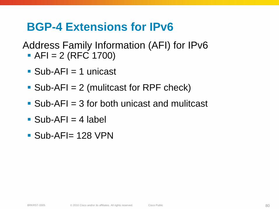
BGP-4 Extensions for IPv6
AFI = 2 (RFC 1700)
Sub-AFI = 1 unicast
Sub-AFI = 2 (mulitcast for RPF check)
Sub-AFI = 3 for both unicast and mulitcast
Sub-AFI = 4 label
Sub-AFI= 128 VPN
Address Family Information (AFI) for IPv6
© 2010 Cisco and/or its affiliates. All rights reserved. Cisco PublicBRKRST-3305 81
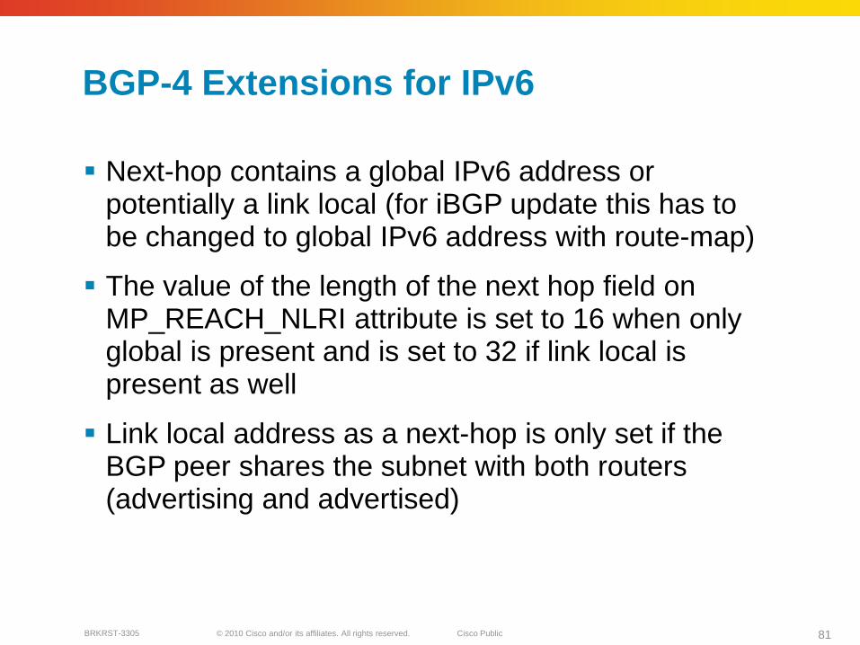
BGP-4 Extensions for IPv6
Next-hop contains a global IPv6 address or potentially a link local (for iBGP update this has to be changed to global IPv6 address with route-map)
The value of the length of the next hop field on MP_REACH_NLRI attribute is set to 16 when only global is present and is set to 32 if link local is present as well
Link local address as a next-hop is only set if the BGP peer shares the subnet with both routers (advertising and advertised)

© 2010 Cisco and/or its affiliates. All rights reserved. Cisco PublicBRKRST-3305 82
BGP-4 Extensions for IPv6
TCP InteractionBGP-4 runs on top of TCP
This connection could be setup either over IPv4 or IPv6
Router IDWhen no IPv4 is configured, an explicit bgp router-id needs to be configured
This is needed as a BGP Identifier, this is used as a tie breaker, and is sent within the OPEN message

© 2010 Cisco and/or its affiliates. All rights reserved. Cisco PublicBRKRST-3305 83
BGP-4 Configurations for IPv6Non-Link Local Peering
Router A
router bgp 100bgp log-neighbor-changesneighbor 2001:100:3:4::1 remote-as 100neighbor 200.10.10.1 remote-as 200!address-family ipv6neighbor 2001:100:3:4::1 activateneighbor 200.10.10.1 activateneighbor 200.10.10.1 route-map SETNH outredistribute connected!route-map SETNH permit 10set ipv6 next-hop 2001:100:3:1::1
AS 100
200.10.10.1
AS 200C
B 2001:100:3:4::1
A
© 2010 Cisco and/or its affiliates. All rights reserved. Cisco PublicBRKRST-3305 84
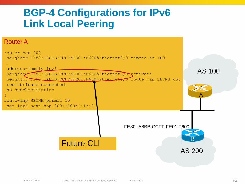
BGP-4 Configurations for IPv6Link Local Peering
Router A
router bgp 200neighbor FE80::A8BB:CCFF:FE01:F600%Ethernet0/0 remote-as 100!address-family ipv6neighbor FE80::A8BB:CCFF:FE01:F600%Ethernet0/0 activateneighbor FE80::A8BB:CCFF:FE01:F600%Ethernet0/0 route-map SETNH outredistribute connectedno synchronization
!route-map SETNH permit 10set ipv6 next-hop 2001:100:1:1::2
AS 100
AS 200
FE80::A8BB:CCFF:FE01:F600
BFuture CLI
A

© 2010 Cisco and/or its affiliates. All rights reserved. Cisco PublicBRKRST-3305 85
RouterA#show bgp ipv6 2001:100:1:1::/64BGP routing table entry for 2001:100:1:1::/64, version 71Paths: (2 available, best #2, table default)
Advertised to update-groups:1
1002001:100:1:1::1 (FE80::A8BB:CCFF:FE01:F600) from FE80::A8BB:CCFF:FE01:F600%Ethernet0/0
(200.11.11.1)Origin incomplete, metric 0, localpref 100, valid, external
Local:: from 0.0.0.0 (200.14.14.1)
Origin incomplete, metric 0, localpref 100, weight 32768, valid, sourced, best
BGP-4 for IPv6 « Show Command »
Show bgp IPv6
© 2010 Cisco and/or its affiliates. All rights reserved. Cisco PublicBRKRST-3305 86
Routing Protocols Co-existence & Convergence

© 2010 Cisco and/or its affiliates. All rights reserved. Cisco PublicBRKRST-3305 87
The Questions Are Almost the Same as for IPv4
Most likely the IPv6 IGP will not be deployed in a brand new network and just by itself
Most likely the IPv4 services are more important at first since they are generating most of the revenue
Redefine “better”
What is the impact on the convergence of IPv4?
Are the resources optimally shared?
Are the topologies going to be congruent?
Etc.
© 2010 Cisco and/or its affiliates. All rights reserved. Cisco PublicBRKRST-3305 88
Co-existence—Convergence Considerations
What IGPs coexist better?
What IPv6 IGP impacts IPv4 the least (hopefully not at all)?
At First, the IPv6 IGP Convergence Might Be Less Important than the Impact of IPv6 on the Convergence of the Existent IPv4 Infrastructure

© 2010 Cisco and/or its affiliates. All rights reserved. Cisco PublicBRKRST-3305 89
Nothing Is for Free
Resources will be shared between the two IGPs and they will compete for processor cycles in a way that reflects their relative configuration
This has implications on:Expected convergence behavior
Single process/topology vs Multi process/topology selection
Resources (Memory, CPU) planning
© 2010 Cisco and/or its affiliates. All rights reserved. Cisco PublicBRKRST-3305 90
Coexistence—Resources Considerations
With the exception of ISIS single topology, the IPv4 and IPv6 routing processes claim their own memory and processing resources for maintaining adjacencies, databases and related calculations
It is important to define the IPv6 network design in order to understand the new resource requirements (memory) and the new operational parameters (max CPU) for the network devices
© 2010 Cisco and/or its affiliates. All rights reserved. Cisco PublicBRKRST-3305 91
Coexistence—Topology Considerations
The IPv4 and IPv6 topologies can be:Congruent
Dual-stack deployment
Non-Congruent Not all network devices are supporting the necessary IPv6 features so they must be avoided during migration
Non-congruent is not necessarily bad, even though it might be more difficult to manage and troubleshoot. Strive for congruent topologies.
© 2010 Cisco and/or its affiliates. All rights reserved. Cisco PublicBRKRST-3305 92
Convergence Considerations
The IGPs Will Compete over Processor Cycles Based on Their Relative Tuning
If you configure the IPv4 and IPv6 IGPs the same way (aggressively tuned for fast convergence), naturally expect a doubling of their stand alone operation convergence time
If the IPv6 IGP is operating under default settings, the convergence time for the optimally tuned IPv4 IGP is not significantly affected
© 2010 Cisco and/or its affiliates. All rights reserved. Cisco PublicBRKRST-3305 93
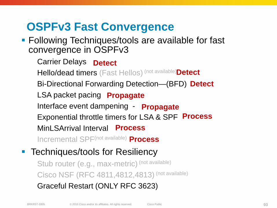
OSPFv3 Fast Convergence Following Techniques/tools are available for fast
convergence in OSPFv3Carrier DelaysHello/dead timers (Fast Hellos) (not available)
Bi-Directional Forwarding Detection—(BFD)LSA packet pacingInterface event dampening -Exponential throttle timers for LSA & SPFMinLSArrival Interval Incremental SPF(not available)
Techniques/tools for ResiliencyStub router (e.g., max-metric) (not available)
Cisco NSF (RFC 4811,4812,4813) (not available)
Graceful Restart (ONLY RFC 3623)
DetectDetect
Detect
Propagate
Propagate
Process
Process
Process
© 2010 Cisco and/or its affiliates. All rights reserved. Cisco PublicBRKRST-3305 94
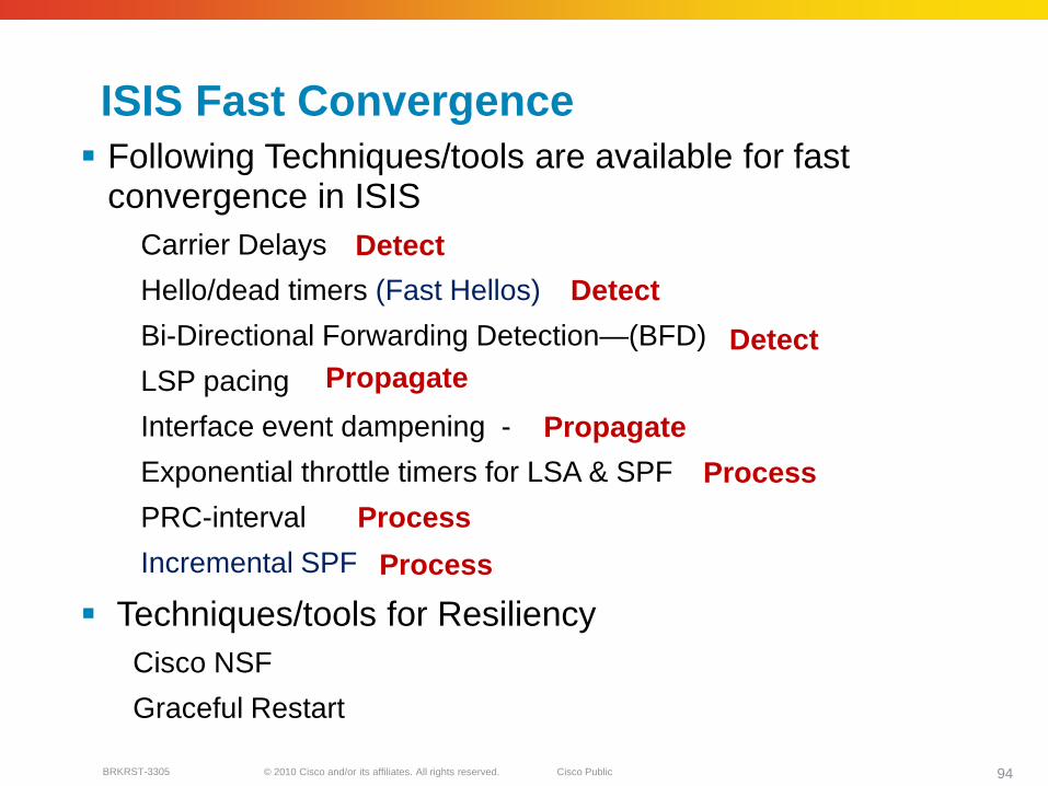
ISIS Fast Convergence Following Techniques/tools are available for fast
convergence in ISISCarrier Delays
Hello/dead timers (Fast Hellos)
Bi-Directional Forwarding Detection—(BFD)
LSP pacing
Interface event dampening -
Exponential throttle timers for LSA & SPF
PRC-interval
Incremental SPF
Techniques/tools for ResiliencyCisco NSF
Graceful Restart
Detect
Detect
Detect
Propagate
Propagate
Process
Process
Process

© 2010 Cisco and/or its affiliates. All rights reserved. Cisco PublicBRKRST-3305 95
Summary
In summary we learned:
Address allocation in both SP and Enterprise networks
SP & Enterprise Architecture
IPv6 Routing deployment techniques
Co-existence & Convergence of Routing protocols

© 2010 Cisco and/or its affiliates. All rights reserved. Cisco PublicBRKRST-3305 96
Complete Your Online Session Evaluation
Give us your feedback and you could win fabulous prizes. Winners announced daily.
Receive 20 Cisco Preferred Access points for each session evaluation you complete.
Complete your session evaluation online now (open a browser through our wireless network to access our portal) or visit one of the Internet stations throughout the Convention Center.
Don’t forget to activate your Cisco Live and Networkers Virtual account for access to all session materials, communities, and on-demand and live activities throughout the year. Activate your account at any internet station or visit www.ciscolivevirtual.com.
© 2010 Cisco and/or its affiliates. All rights reserved. Cisco PublicBRKRST-3305 97