advanced investigations on a simplified modeling method of ......illustrated. as described in the...
TRANSCRIPT
11. LS-DYNA Forum, Ulm, 2012
© 2012 Copyright by DYNAmore GmbH
Advanced investigations on a simplified modeling method of self-piercing riveted joints for crash
simulation
M. Bier, S. Sommer
Fraunhofer-Institut für Werkstoffmechanik IWM, Freiburg, Germany
1 Introduction
The requirements for energy efficiency and lightweight construction in automotive engineering rise steadily. Therefore a maximum flexibility of the used materials is necessary and new joining techniques are constantly developed. The resulting large number of joints with different properties leads to the need to provide for each type an appropriate modeling method for crash simulation. In this paper a simplified model of a self-piercing riveted joint for crash simulation will be investigated. The advantage of a self-piercing riveted joint in contrast to other joining methods such as spot-welding is to combine materials with different properties such as aluminum and steel. Also the joining process of self-piercing rivets does not affect the microstructure and thus the properties of the joined materials, as can be observed in thermal joining processes. In previous studies various simplified models have been developed and tested for their applicability for self-piercing riveted joints. The strengths and weaknesses of each model were identified. Hanssen et al. [1] developed a model, which represents the behavior of the joint by constraints between two sets of nodes located at the joined sheets. This model is implemented in LS-Dyna and can be selected in the current version by using the keyword *CONSTRAINED_SPR2 [2]. Hanssen et al. have described, that it is possible to fit the force-displacement curves of the experiments, shown by Porcaro et al. [3], by adjustment of the appropriate parameters. Double u-shaped profiles were examined, which were loaded at 90° (tension), 0° (shear) and 45° (combined shear-tesnion). In addition a peeling specimen was considered and included in the parameter adjustment. Strain rate effects were neglected in these studies. Sommer and Maier [4] give an overview of the available simplified models in LS-Dyna. In addition to the above modeling method by constraints (e.g. *CONSTRAINED_SPR2/_SPR3) cohesive material models (e.g. *MAT_240) and simplified models for spot-welds (*MAT_100 respectively *MAT_100_DA) were used. The simulation results of KS-2 experiments [5] under 0° (shear), 30°, 60° (combination of shear and tension), 90° (tension) load and of peeling tests with these simplified elements were compared and evaluated in terms of their suitability for the modeling of self-piercing riveted connections in crash simulations. As a result it was stated, that cohesive element in combination with the material *MAT_240 [6] is most suitable for modeling self-piercing riveted connections. In this paper the behavior of the *CONSTRAINED_SPR3 [2] model will be discussed in detail. The simplified model *CONSTRAINED_SPR3 (also known as *CONSTRAINED_INTERPOLATION_ SPOTWELD) is a modified version of the *CONSTRAINED_SPR2 model and was originally developed for the use in simulation of spot-welds. Due to its flexibility in the modeling of plastic behavior it is possible to use it also for modeling of self-piercing riveted connections. This flexibility leads to an increased effort in the determination of the model parameters. This is one reason, why the *CONSTRAINED_SPR3 has not been considered in previous studies. At this point the increased effort in comparison to other simplified models will be accepted with the objective of an improved description of the connection behavior.

11. LS-DYNA Forum, Ulm, 2012
© 2012 Copyright by DYNAmore GmbH
2 Experimental database
All experiments, which will be used as a reference, were carried out as a part of the AiF-project „Experimentelle Untersuchung und Simulation des Crashverhaltens mechanisch gefügter Verbindungen“, IGF-Vorhaben 352 ZBG, at the Laboratorium für Werkstoff- und Fügetechnik LWF in Paderborn. To characterize the behavior of the self-piercing rivet joint, several tests with the LWF-KS-2 measuring concept (see Fig. 2a) were made. This concept is defined by specimens, which can be tested under different load angles and loading rates. The specimens consist of two separate u-sections, which are joined together by one punctiform joining technology, which will be characterized. In our case four different load angles are taken into account, KS-2-0° (pure shear), KS-2-90° (pure tensile), KS-2-30° and KS-2-60° (combination of shear and tensile load). In addition tests with peeling specimens were performed, which are similar to KS-2-90° with one-sided load. The results of these five different experiments are shown in Fig. 2b and Fig. 1a. If we plot the maximum forces spit ideally in normal and shear fraction according to the global load angle in a diagram (Fig. 2c), which displays the normal force over the shear force, we can interpret the mixed mode behavior of the connection. The result of the peeling specimen can’t be added to the diagram, because of the unknown load of the rivet. For validation T-joint experiments were made (Fig. 1c). In Fig. 1b the geometry of the specimen and the load direction (cross the sill) are shown.
Fig. 2: a) LWF-KS-2 specimen with schematic illustration of the different load angles [7]; b) results of the experiments with KS-2 specimens (0° - black, 30° - blue, 60° - purple, 90° - red); c) diagram of the maximum forces split in shear and normal/tensile fraction
a) b) c)
Fig. 1: a) results of the peeling test; b) geometry of the T-joint test (load – red arrow); c) results of the T-joint test
a) b) c)
11. LS-DYNA Forum, Ulm, 2012
© 2012 Copyright by DYNAmore GmbH
3 Simplified modeling
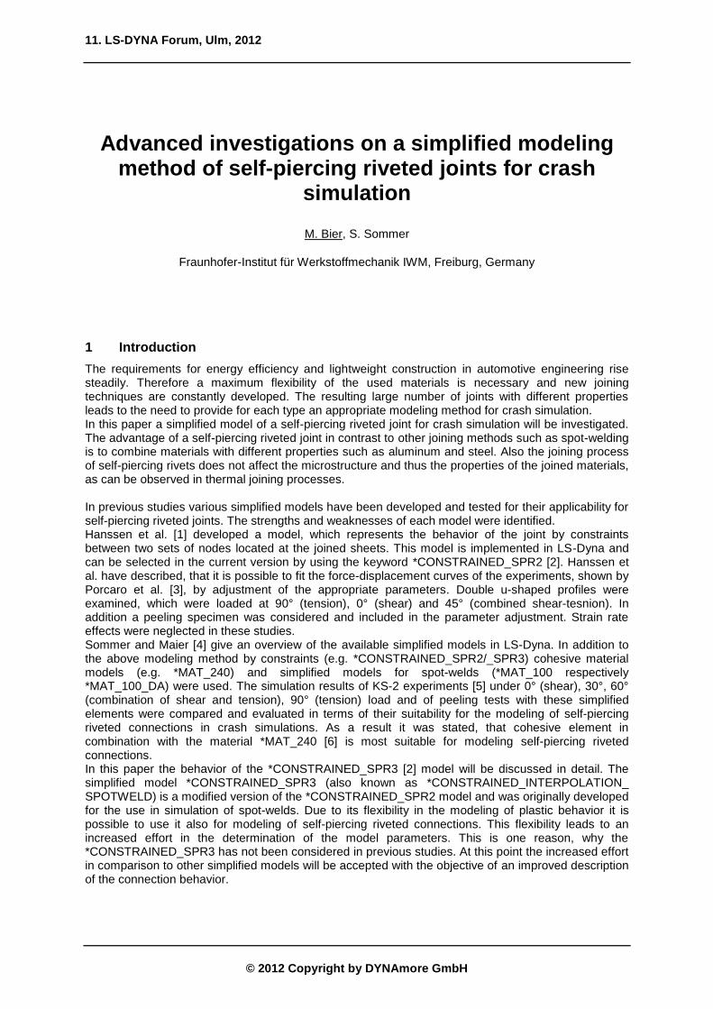
The geometry of the specimen is modeled by Belytschko-Tsay shell elements (ELFORM=2). The used mesh is shown in Fig. 3. Therefore the element edge length is about 2.5 mm (see Fig. 3). In this investigation two different versions of *CONSTRAINED_SPR3 will be used as simplified model. On the one hand a version as it is currently implemented in LS-DYNA (Version 971 R6.1.0), on the other hand a modified version, which will be called *CONSTRAINED_SPR3_IWM subsequently.
3.1 *CONSTRAINED_INTERPOLATION_SPOTWELD (*CONSTRAINED_SPR3)
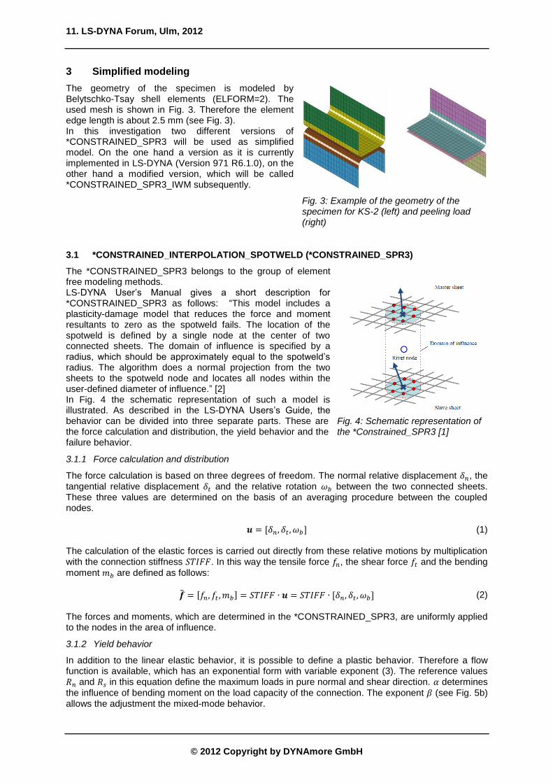
The *CONSTRAINED_SPR3 belongs to the group of element free modeling methods. LS-DYNA User’s Manual gives a short description for *CONSTRAINED_SPR3 as follows: “This model includes a plasticity-damage model that reduces the force and moment resultants to zero as the spotweld fails. The location of the spotweld is defined by a single node at the center of two connected sheets. The domain of influence is specified by a radius, which should be approximately equal to the spotweld’s radius. The algorithm does a normal projection from the two sheets to the spotweld node and locates all nodes within the user-defined diameter of influence.” [2] In Fig. 4 the schematic representation of such a model is illustrated. As described in the LS-DYNA Users’s Guide, the behavior can be divided into three separate parts. These are the force calculation and distribution, the yield behavior and the failure behavior.
3.1.1 Force calculation and distribution
The force calculation is based on three degrees of freedom. The normal relative displacement , the tangential relative displacement and the relative rotation between the two connected sheets. These three values are determined on the basis of an averaging procedure between the coupled nodes. (1) The calculation of the elastic forces is carried out directly from these relative motions by multiplication with the connection stiffness . In this way the tensile force , the shear force and the bending
moment are defined as follows:
(2)
The forces and moments, which are determined in the *CONSTRAINED_SPR3, are uniformly applied to the nodes in the area of influence.
3.1.2 Yield behavior
In addition to the linear elastic behavior, it is possible to define a plastic behavior. Therefore a flow function is available, which has an exponential form with variable exponent (3). The reference values and in this equation define the maximum loads in pure normal and shear direction. determines
the influence of bending moment on the load capacity of the connection. The exponent (see Fig. 5b) allows the adjustment the mixed-mode behavior.
Fig. 3: Example of the geometry of the specimen for KS-2 (left) and peeling load (right)
Fig. 4: Schematic representation of the *Constrained_SPR3 [1]

11. LS-DYNA Forum, Ulm, 2012
© 2012 Copyright by DYNAmore GmbH
[(
)
(
)
]
( ) (3)
By the definition of the flow curve ( ) it is possible to realize a non-ideal-plastic behavior. In this
respect, ( ) describes the dependence of the equivalent force on the calculated plastic equivalent displacement (see Fig. 5).
3.1.3 Failure behavior
The damage and failure behavior of the *CONSTRAINED_SPR3 is implemented by the definition of two plastic equivalent displacements. Firstly, the plastic equivalent displacements at the time of
damage initiation
and secondly the plastic equivalent displacements at failure
. These two
values can each be specified by a table of values as a function of the mixed-mode parameter (equation (4)). Thus, a different failure behavior between normal and shear loads is implemented.
(
) (4)
( ) (5)
( ( )
( )) (6)
( )
( ( )
( )) (7)
If equation (5) is met, damage initiates and the transmitted forces are reduced linearly by a factor (equation (7)). At the time of meeting equation (6) the joint will fail and the connection will be separated.
3.2 *CONSTRAINED_SPR3_IWM
In this section the *CONSTRAINED_SPR3_IWM, which is a modified version of the *CONSTRAINED_SPR3 implemented in LS-Dyna, will be described. In the *CONSTRAINED_SPR3_IWM the flow behavior and the rate-dependent model were modified in comparison to the *CONSTRAINED_SPR3. Further no calculation of the bending moment will be done, but a symmetry factor will be introduced. This factor is a function of the angle between the two calculated sheet normals of the joint partners and not a function of the plastic equivalent
displacement .
( ( )) (8)
(
) (9)
Fig. 5: a) flow curve [2]; b) the flow function variation depending on 𝛽
a) b)
11. LS-DYNA Forum, Ulm, 2012
© 2012 Copyright by DYNAmore GmbH
3.2.1 Modified yield behavior
The structure of the flow behavior is identical in *CONSTRAINED_SPR3 and *CONSTRAINED_SPR3_IMW, but the part of the bending moment is omitted and a consideration of the symmetry factor is added.
[(
( ))
(
)
]
( ) (10)
3.2.2 Strain-rate dependent model
A model to describe the rate-dependent effects is included in the *CONSTRAINED_SPR3_IWM.
Therefore a linear approach of the rate-dependency of and on a plastic equivalent strain rate
is implemented. and
are the reference values of the load capacity under quasi-static load.
and are proportionality factors to describe the linear rate-dependency.
( )
(11)
( )
(12)
4 Simulation with *CONSTRAINED_SPR3
At first simulations with the default *CONSTRAINED_SPR3 were done. The objective of these simulations was to evaluate the quality of the *CONSTRAINED_SPR3 as a simplified model for self-piercing riveted connections. For this purpose, the quasi-static tests were used (Fig. 2b).
4.1 Parameter Identification
The parameter identification is done in several steps: 1. Determination of the connection stiffness using the KS-2-0° specimen 2. Definition of the flow curve also by using the KS-2-0° specimen. Thereby a horizontal plateau
after reaching the maximum value and a normalization of the flow curve is useful. 3. Determination of the reference values and using the KS-2-90° and 0° results
4. Determination of the exponent using the KS-2-60° and 30° results
5. Fitting the values of ( ) and
( ) to define the failure behavior
4.2 Results
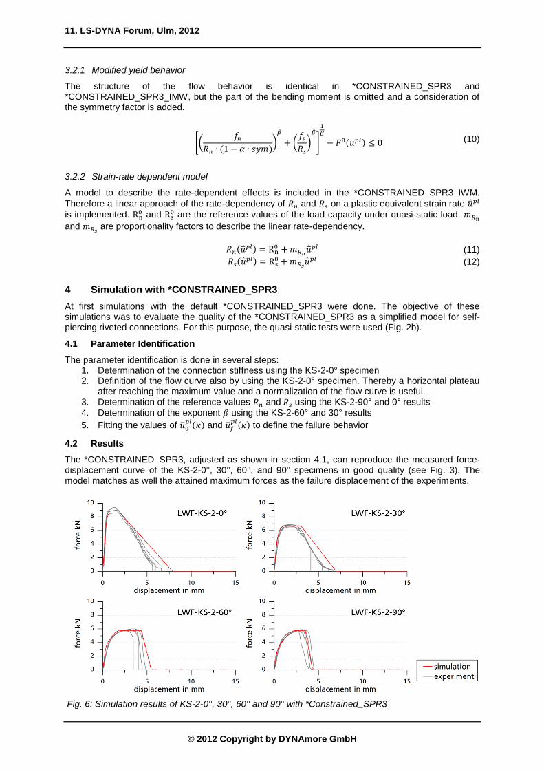
The *CONSTRAINED_SPR3, adjusted as shown in section 4.1, can reproduce the measured force-displacement curve of the KS-2-0°, 30°, 60°, and 90° specimens in good quality (see Fig. 3). The model matches as well the attained maximum forces as the failure displacement of the experiments.
Fig. 6: Simulation results of KS-2-0°, 30°, 60° and 90° with *Constrained_SPR3

11. LS-DYNA Forum, Ulm, 2012
© 2012 Copyright by DYNAmore GmbH
A weakness of the model appears in simulation of experiments with peeling specimen (Fig. 7). The simulation of the peeling specimen using the parameter set, which was determined on the KS-0°, 30°, 60° and 90° experiments, differs from the experiments in both the maximum force and the failure displacement. At this point it should be noted, that in determination of the parameters, the influence of the bending moment was not included (i.e. ). However an appropriate choice of the value of to adjust the peeling simulation is not effective, because the form of the flow function mostly leads to a reduction of the bending moment to zero, when the *CONSTRAINED_SPR3 starts yielding. Hence the value of has no influence on the maximum force and the failure displacement of the model.
5 Simulation with detailed model
In section 4.2 it was found that the *CONSTRAINED_SPR3 model provides an inadequate reproduction of the peeling experiments. In the following the motivation will be exemplified, why the yield behavior of the *CONSTRAINED_SPR3_IWM was modified as shown (section 3.2). Therefore the characteristic behavior of a self-piercing rivet joint under peeling load will be considered based on detailed simulations. It will be discussed in particular, if the peeling load is just a special case of mixed-mode load. If this would be true, the differences between the simulation with the *CONSTRAINED_SPR3 model and the experiments in case of peeling load would be reduced to an inaccurately defined model for the mixed mode behavior.
5.1 Model
The detailed model is based on two different data sets, which have been jointly used for the development of the model (Fig. 8). The geometry was determined with the help of a microsection. Information about the local hardening state was derived from a process simulation. Four different material zones with different pre-hardening were identified and considered in the detailed model. In the detailed model solid elements with reduced integration were used with an approximate element length of 0.15 mm. The detailed model was integrated in the corresponding specimen geometries in order to simulate the experiments.
5.2 Results
In a first step a simulation of the KS-90° test was performed to evaluate the quality of the detailed model. In comparison with the experimental database, a high reproduction quality of the connection behavior can be determined (see Fig. 9). The maximum forces in the simulation and the experiment coincide with a deviation of 6.4 % (sim.: 6.2 kN – exp.: 5.9 kN). Also in failure displacement and energy absorption of the joint only small deviations between experiment and simulation can be observed. In summary, the quality of the model can be classified as appropriate. As a second step, the simulation of the peeling specimen was investigated. As well
Fig. 7: Simulation results of the peeling tests with *Constrained_SPR3
Fig. 8: Development process and cross section of the detailed model
Fig. 9: Result of the simulation with detailed model (KS-90°)
11. LS-DYNA Forum, Ulm, 2012
© 2012 Copyright by DYNAmore GmbH
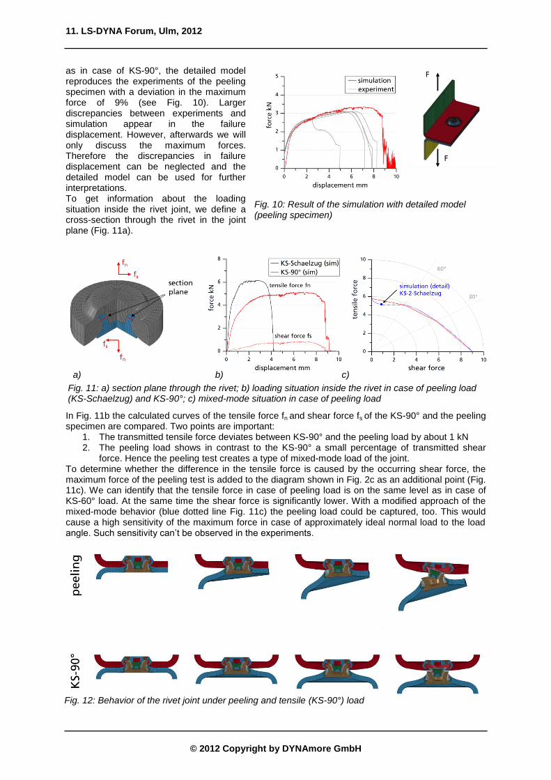
as in case of KS-90°, the detailed model reproduces the experiments of the peeling specimen with a deviation in the maximum force of 9% (see Fig. 10). Larger discrepancies between experiments and simulation appear in the failure displacement. However, afterwards we will only discuss the maximum forces. Therefore the discrepancies in failure displacement can be neglected and the detailed model can be used for further interpretations. To get information about the loading situation inside the rivet joint, we define a cross-section through the rivet in the joint plane (Fig. 11a).
In Fig. 11b the calculated curves of the tensile force fn and shear force fs of the KS-90° and the peeling specimen are compared. Two points are important:
1. The transmitted tensile force deviates between KS-90° and the peeling load by about 1 kN 2. The peeling load shows in contrast to the KS-90° a small percentage of transmitted shear
force. Hence the peeling test creates a type of mixed-mode load of the joint. To determine whether the difference in the tensile force is caused by the occurring shear force, the maximum force of the peeling test is added to the diagram shown in Fig. 2c as an additional point (Fig. 11c). We can identify that the tensile force in case of peeling load is on the same level as in case of KS-60° load. At the same time the shear force is significantly lower. With a modified approach of the mixed-mode behavior (blue dotted line Fig. 11c) the peeling load could be captured, too. This would cause a high sensitivity of the maximum force in case of approximately ideal normal load to the load angle. Such sensitivity can’t be observed in the experiments.
Fig. 10: Result of the simulation with detailed model (peeling specimen)
a) b) c)
Fig. 11: a) section plane through the rivet; b) loading situation inside the rivet in case of peeling load (KS-Schaelzug) and KS-90°; c) mixed-mode situation in case of peeling load
Fig. 12: Behavior of the rivet joint under peeling and tensile (KS-90°) load
11. LS-DYNA Forum, Ulm, 2012
© 2012 Copyright by DYNAmore GmbH
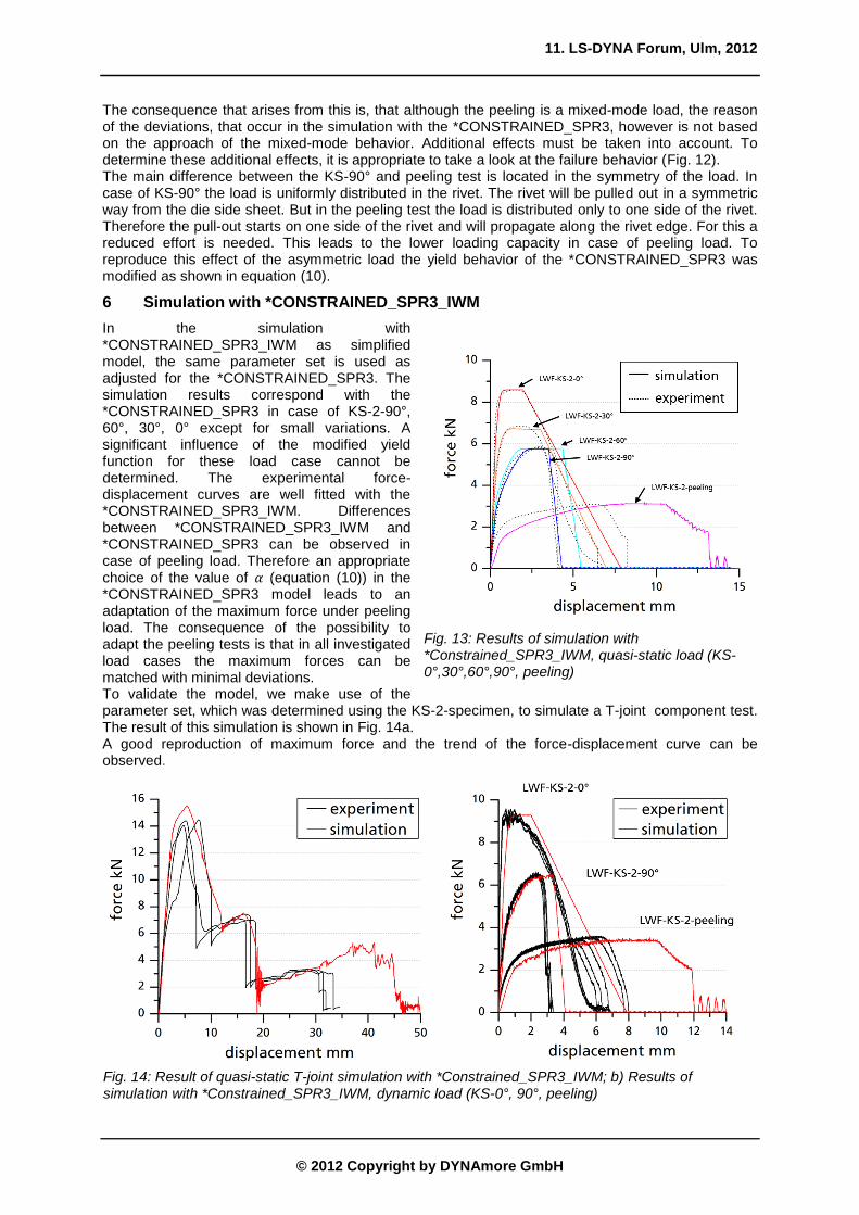
The consequence that arises from this is, that although the peeling is a mixed-mode load, the reason of the deviations, that occur in the simulation with the *CONSTRAINED_SPR3, however is not based on the approach of the mixed-mode behavior. Additional effects must be taken into account. To determine these additional effects, it is appropriate to take a look at the failure behavior (Fig. 12). The main difference between the KS-90° and peeling test is located in the symmetry of the load. In case of KS-90° the load is uniformly distributed in the rivet. The rivet will be pulled out in a symmetric way from the die side sheet. But in the peeling test the load is distributed only to one side of the rivet. Therefore the pull-out starts on one side of the rivet and will propagate along the rivet edge. For this a reduced effort is needed. This leads to the lower loading capacity in case of peeling load. To reproduce this effect of the asymmetric load the yield behavior of the *CONSTRAINED_SPR3 was modified as shown in equation (10).
6 Simulation with *CONSTRAINED_SPR3_IWM
In the simulation with *CONSTRAINED_SPR3_IWM as simplified model, the same parameter set is used as adjusted for the *CONSTRAINED_SPR3. The simulation results correspond with the *CONSTRAINED_SPR3 in case of KS-2-90°, 60°, 30°, 0° except for small variations. A significant influence of the modified yield function for these load case cannot be determined. The experimental force-displacement curves are well fitted with the *CONSTRAINED_SPR3_IWM. Differences between *CONSTRAINED_SPR3_IWM and *CONSTRAINED_SPR3 can be observed in case of peeling load. Therefore an appropriate choice of the value of (equation (10)) in the *CONSTRAINED_SPR3 model leads to an adaptation of the maximum force under peeling load. The consequence of the possibility to adapt the peeling tests is that in all investigated load cases the maximum forces can be matched with minimal deviations. To validate the model, we make use of the parameter set, which was determined using the KS-2-specimen, to simulate a T-joint component test. The result of this simulation is shown in Fig. 14a. A good reproduction of maximum force and the trend of the force-displacement curve can be observed.
Fig. 13: Results of simulation with *Constrained_SPR3_IWM, quasi-static load (KS-0°,30°,60°,90°, peeling)
Fig. 14: Result of quasi-static T-joint simulation with *Constrained_SPR3_IWM; b) Results of simulation with *Constrained_SPR3_IWM, dynamic load (KS-0°, 90°, peeling)

11. LS-DYNA Forum, Ulm, 2012
© 2012 Copyright by DYNAmore GmbH
Considering now in addition to the quasi-static KS- and peeling tests identical experiments under dynamic load it can be seen that the appearing effects can be represented by the strain-rate model of the *CONSTRAINED_SPR3 (Fig. 14b). Only the adjustment of rate dependent model is enough to fit the rate dependent effects in maximum force. The effects, which cannot be represented, are the changes in the failure displacement at higher loading rates.
7 Conclusion
It has been shown, that the *CONSTRAINED_SPR3 is suitable as a simplified model for the simulation of joints with self-piercing rivets under quasi-static pure shear/normal and mixed-mode load. If the rivet connection isn’t uniformly loaded, as it is observed in case of peeling load, the *CONSTRAINED_SPR3 shows deficits in the reproduction quality of the joint behavior. On the basis of a detailed model the peeling load case was investigated. The objective of this investigation was to motivate the modification of the *CONSTRAINED_SPR3, which were made in the *CONSTRAINED_SPR3_IWM. It could be determined that the peeling load is a special kind of a mixed-mode load. However an additional symmetry effect was observed, which leads to a reduction of the maximum normal forces under peeling load. Hence a changed approach of the mixed-mode model induces not in general an improvement of the model quality. This motivates the modifications in the *CONSTRAINED_SPR3_IWM, which include the symmetry effect in the yield behavior of the model. With the *CONSTRAINED_SPR3_IWM all exemplary KS-2-tests, including the peeling load, could be reproduced in a good quality. The model and the parameter set were validated using the simulation of the T-joint component test. Also simple strain rate effects were considered in the model. To conclude this investigation we can note, that the *CONSTRAINED_SPR3_IWM is an adequate simplified model for self-piercing rivet connections in crash simulations. Only a deviation in the failure displacement under peeling load remains a task for further investigations.
8 Acknowledgments
The results presented are funded with budget funds of the Federal Ministry of Economics and Technology (BMWi) via the German Federation of Industrial Research Associations AiF (IGF-Nr. 352 ZBG) and supported by the Forschungsvereinigung Stahlanwendung e.V. FOSTA, Duesseldorf (Research Association for Steel Application). The authors would like to thank all parties involved for the funding and the support. Sincere thanks are also given to all cooperating companies and their representatives for the cooperation during the project.
9 Literature
[1] A.G. Hanssen, L. Olovsson, R. Porcaro, M. Langseth: “A large-scale finite element point-connector model for self-piercing rivet connections”, European Journal of Mechanics A/Solids 29, 2010, 484-495
[2] LS-DYNA Keyword Users’s Manual, Version 971 R6.0.0, Livermore Software Technology Corporation (LSTC), 2012
[3] R. Porcaro, A.G. Hanssen, M. Langseth, A. Aalberg: „The behaviour of a self-piercing riveted connection under quasi-static loading conditions“, International Journal of Solids and Structures 43, 2006, 5110-5131
[4] S. Sommer, J. Maier: “Failure Modeling of a self-piercing riveted joint using LS-DYNA”, Proceedings 8th European LS-DYNA Conference, Strasbourg, 2011
[5] O.Hahn: “Probe und Probenspannvorrichtung zum Einsatz in Zugprüfmaschinen”, Patentnummer DE 195 22 247 A1, 1995
[6] S. Marzi: “Ein ratenabhängiges, elasto-plastisches Kohäsivzonenmodell zur Berechnung struktureller Klebverbindungen unter Crashbeanspruchung”, Dissertation, Aachen, 2010
[7] O. Hahn, M. Wissling, F. Klokkers: „Ermittlung wahrer Kennwerte für geschraubte und stanzgenietete Blechverbindungen unter schlagartiger Belastung“, EFB-Forschungsbericht Nr. 297, 2009