advanced hydraulic motion control design practices
TRANSCRIPT

Advanced Hydraulic Motion Control
Design Practices
1
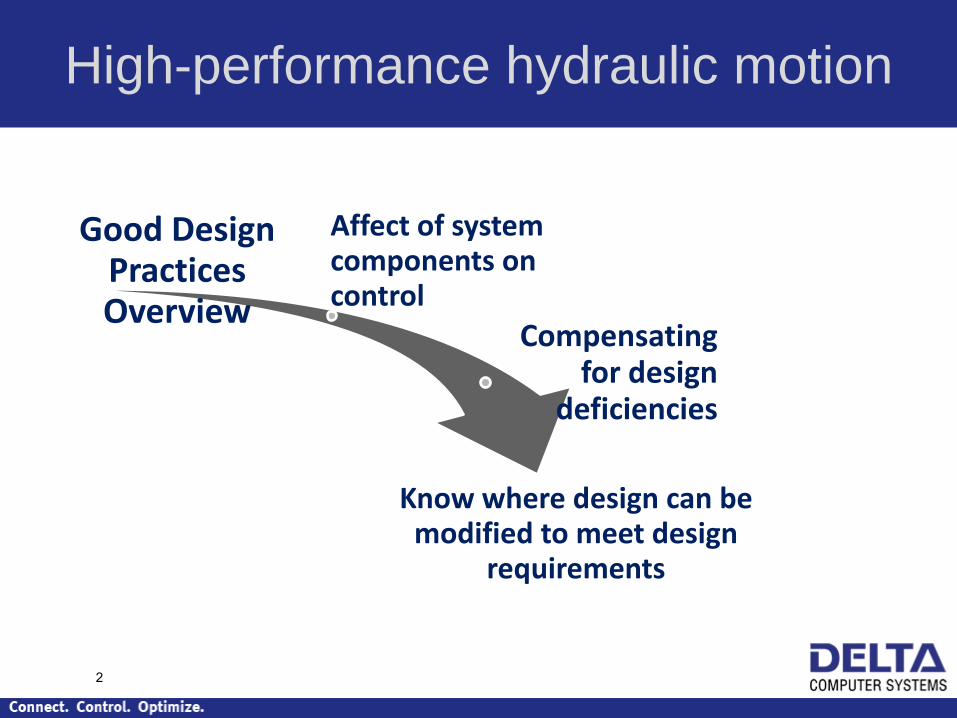
Good Design Practices Overview
Affect of system components on control
Compensating for design
deficiencies
Know where design can be modified to meet design
requirements
High-performance hydraulic motion
2

Feedbac
k
Accumulato
r
Cylinder
Good Valve Hard Piping
Reservoi
r
Pump
Controller
3

Good Design is Simple!
4

Good Design Provides…
• Excellent Control!
– Accuracy < 0.001 inch, even while moving
– Complex motion profiles
– Synchronization (no flow dividers)
• Smooth startup
• Less maintenance
• Less tech support
• Higher Initial Cost (not always)
• May not be possible
5

• Cost
– Valve: good valves are much more expensive
– Feedback: high resolution is more expensive
– Larger cylinder larger valve larger pump
• Availability
– Linear valves may have longer lead times (Rexroth)
• Special requirements
– Space constraints: valve location
– Environment: valve location
Real-life design pressures
6

Real-life design pressures
Understanding
control features Meet Design
Requirement
s
7

Closed-Loop Control Review
8
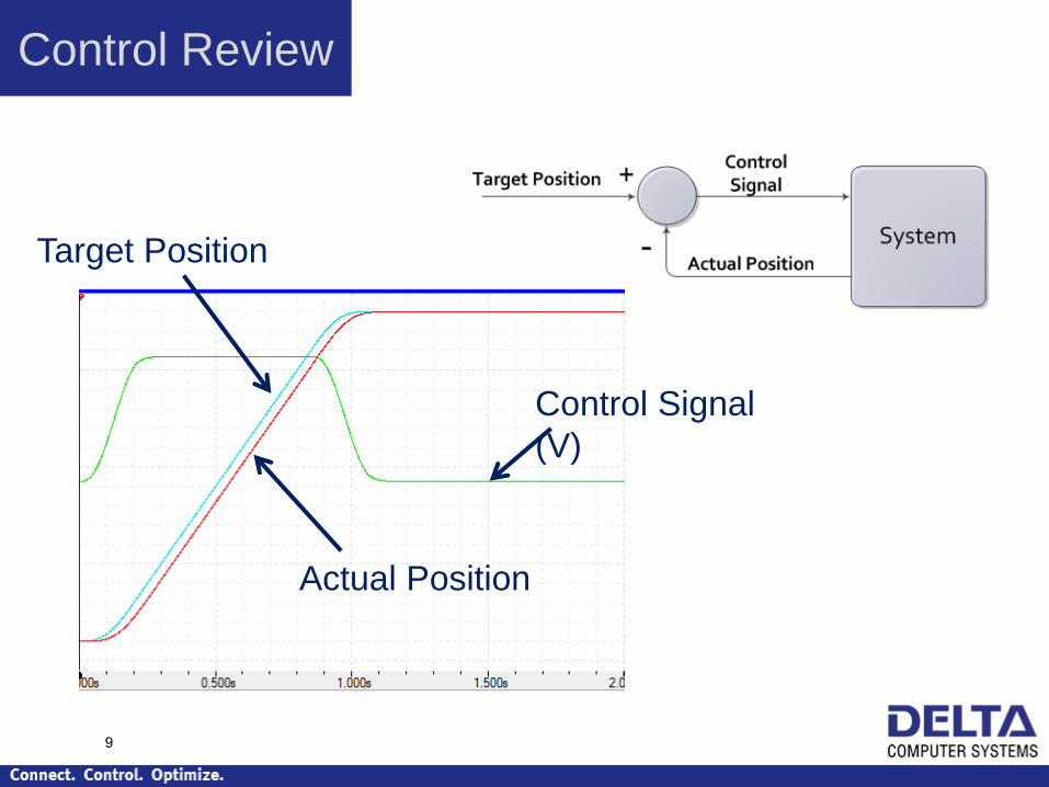
Control Review
Target Position
Actual Position
Control Signal
(V)
9

• Proportional Gain
• Integral Gain
• Differential Gain
• Velocity Feed
Forward
• Acceleration Feed
Forward
Each PID gain contributes to the control output
signal
Control Review
10
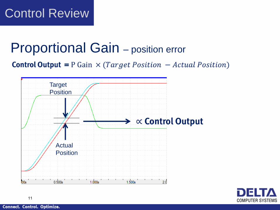
Proportional Gain – position error
Target
Position
Actual
Position
Control Review
11

Integral Gain – sum of position error
Target
Position
Actual
Position
Control Review
12

Integral Gain can cause overshoot
Winds up during
error
If it winds up, it must wind down! Unwinding causes
overshoot
Control Review
13

Differential Gain – velocity error
Target
Velocity
Actual
Velocity
Control Review
14

Quantization Noise Affects D Gain
Actual Velocity is
“noisy”
This results in a “noisy”
Control Output
Because velocity is calculated from position, not measured directly
Control Review
TODO Output Filter
15

Velocity Feed Forward – prior knowledge of
velocity
Target
Velocity
Because the actual velocity is
proportional to the voltage to the valve
Example:
1 V ≈ 3 in./sec
2 V ≈ 6 in./sec
3 V ≈ 9 in./sec
Etc.
Control Review
16

Acceleration Feed Forward – prior knowledge of
acceleration
Target
Acceleration
Because F = m∙A
The extra “boost” needed is
proportional to the Target Acceleration
Control Review
17

Feed Forwards – eliminating error
P, I and D Gains operate only if an error exists
PID-only will not follow target exactly
Feed Forwards eliminate error
Control Review
18

Important!
Control Review
Gains and feed forwards are linear equations!
Therefore,
The hydraulic system should
be as linear as possible!
19

How Components Affect Control
20
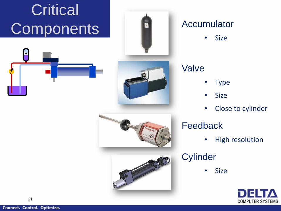
Accumulator
• Size
Valve
• Type
• Size
• Close to cylinder
Feedback
• High resolution
Cylinder
• Size
Critical
Components
21

Accumulator
Provides constant
supply pressure to valve
Locate close to valve.
Sizing is easy.
Helps provide
linear
system!
22
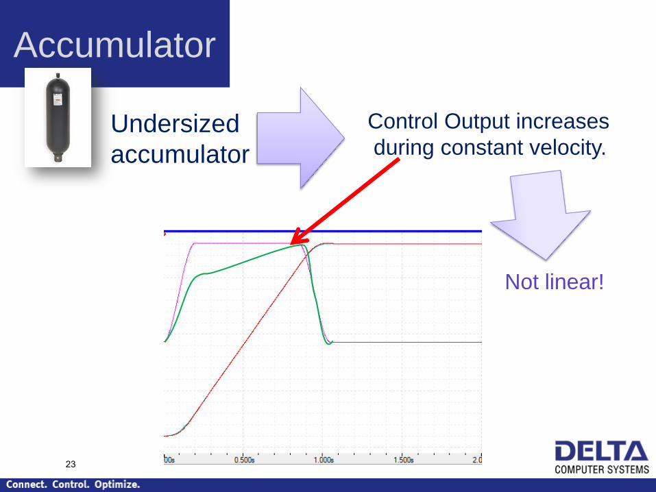
Accumulator
Undersized
accumulator
Control Output increases
during constant velocity.
Not linear!
23

Valve
Best Practice:
• Linear
• Zero-lapped
• High response
• Locate on cylinder
with hard pipe to rod
end
24

Valve
Counterbalance
Valves
25

Valve Linear vs. Non-linear
Spool
Linear Single knee Curvilinear
26
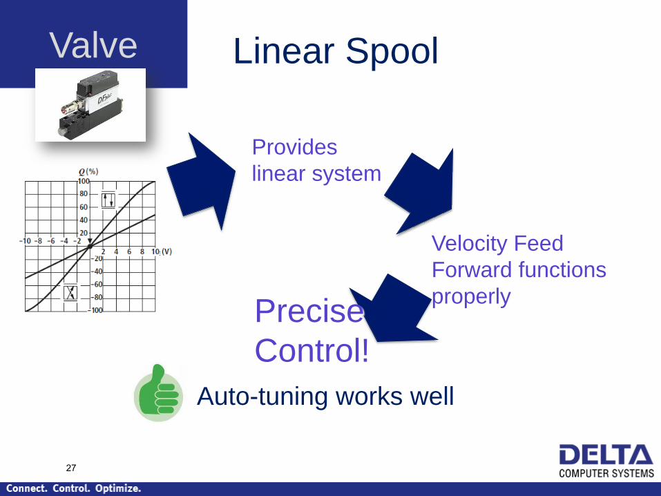
Valve Linear Spool
Provides
linear system
Velocity Feed
Forward functions
properly Precise
Control!
Auto-tuning works well
27

Valve Single-Knee Spool
Valve-
linearization
algorithm
Appears
linear to PID
and feed
forwards
Good
Control
28
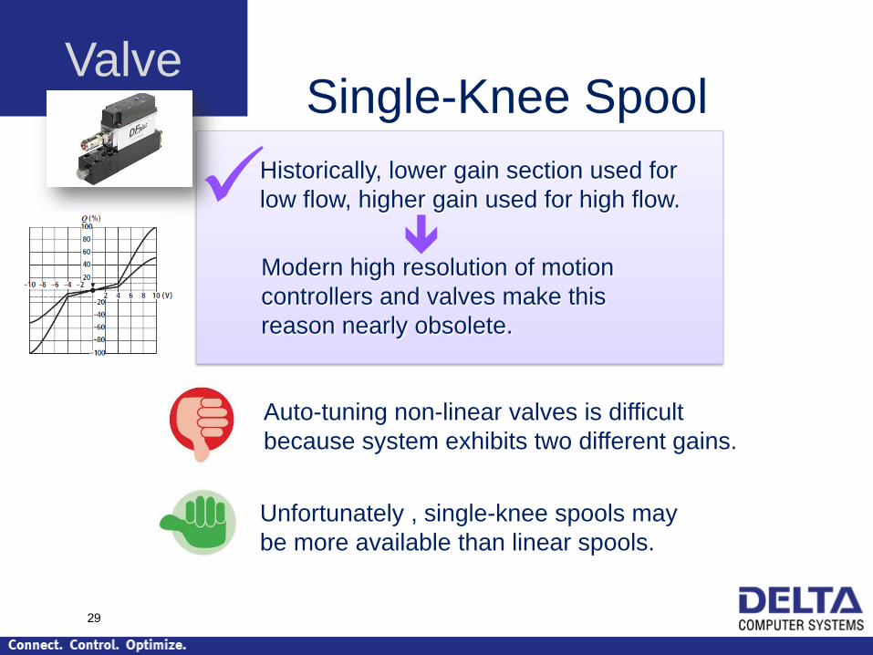
Valve Single-Knee Spool
Auto-tuning non-linear valves is difficult
because system exhibits two different gains.
Unfortunately , single-knee spools may
be more available than linear spools.
Historically, lower gain section used for
low flow, higher gain used for high flow.
Modern high resolution of motion
controllers and valves make this
reason nearly obsolete.
29

Valve Curvilinear Spool
Auto-tuning is difficult because system
exhibits multiple gains.
Less expensive.
Typically used in less expensive valves
Valve Linearization is possible, but difficult.
30

Valve Effects of Non-linear
Spool (especially curvilinear)
Imperfect Valve Linearization
Poor tracking during move
Integrator Windup
Overshoot
One Solution:
Turn of integrator during move. Won’t track
well, but will not overshoot and will hold final
position. 31

Valve Overlapped
Spools (deadband)
No motion until Control Output reaches deadband value.
Spool travel delay causes more problems.
Doesn’t accurately
reach position
32

Valve Deadband Compensation
Always add positive or negative
Deadband value to Control Output
Deadband value
“Hunts” when holding position
33
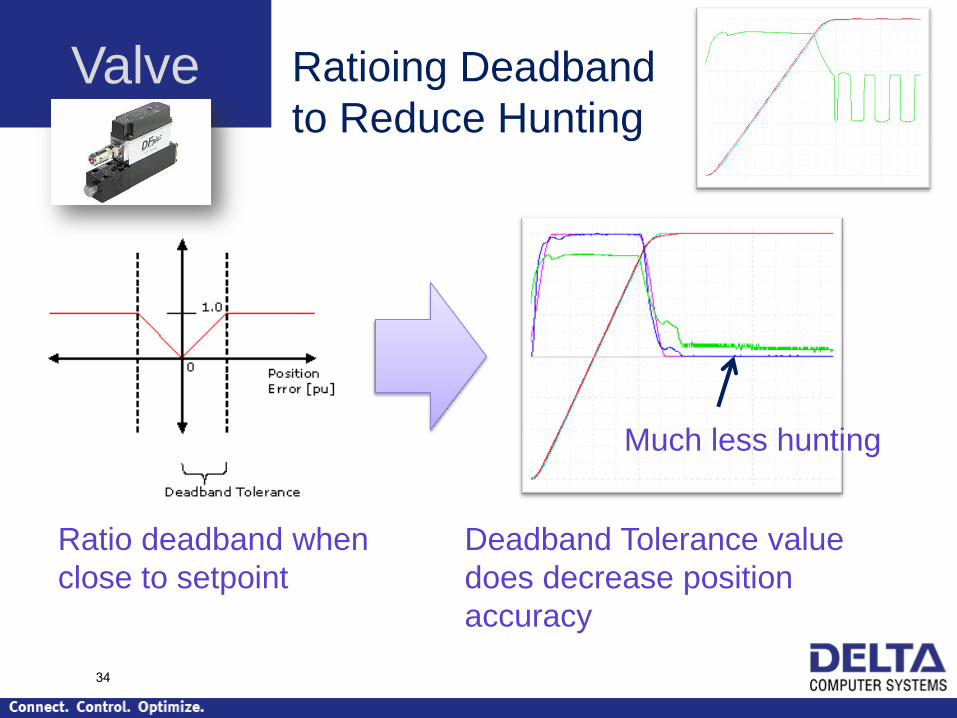
Valve Ratioing Deadband
to Reduce Hunting
Ratio deadband when
close to setpoint
Much less hunting
Deadband Tolerance value
does decrease position
accuracy
34

Valve Overlapped Spools
Tuning is difficult
Typically less expensive
Not for rapid deceleration
Auto-tuning is nearly impossible
Not for rapid direction changes
Nearly leak-free at 0 volts
35
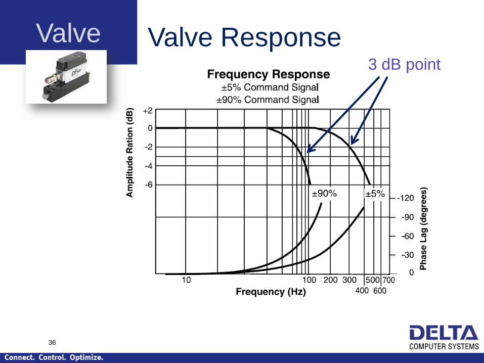
Valve Valve Response 3 dB point
36
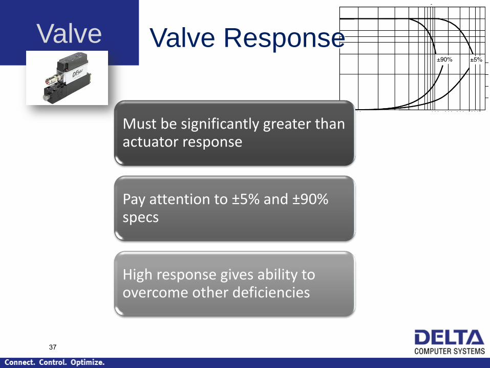
Valve Valve Response
Must be significantly greater than actuator response
Pay attention to ±5% and ±90% specs
High response gives ability to overcome other deficiencies
37

Position Sensors
Magnetostrictive rules!
• Rugged
• Non-contact
• Mounts in cylinder
38
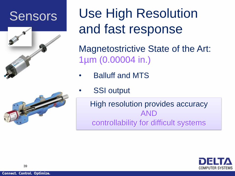
Sensors Use High Resolution
and fast response
Magnetostrictive State of the Art:
1µm (0.00004 in.)
• Balluff and MTS
• SSI output
High resolution provides accuracy
AND
controllability for difficult systems
39

Sensors Magnetostrictive Outputs
SSI – digital, noise immune, accurate
Start/Stop or PWM – timing dependent,
Resolutions to 0.0005, better with recircs
40

Sensors Magnetostrictive Outputs
Analog is noisy!
Beware “infinite” resolution
Is acceptable for short travel.
Filtering is possible, but introduces
phase delay.
41

Sensors Other position sensor options
Externally mounted magnetostrictive
String Potentiometer
• String can oscillate
• Filtering is difficult because oscillation is similar to motion frequency.
• Use only if absolutely necessary
42

Cylinders
Flow makes it
go
F = m ∙ A • Provide Force
• Provide Stiffness
Size Bore Diameter to…
43

Cylinders Cylinder Stiffness
Narrow bore:
Wide bore:
Mass
Mass
Sloppy control
Tight control
44

Cylinders Remote Valve is similar to
Narrow Cylinder
45
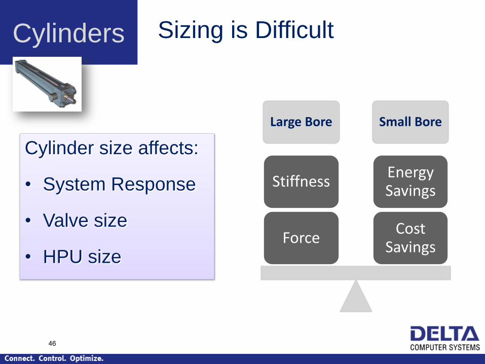
Cylinders
Large Bore Small Bore
Cost Savings
Energy Savings
Force
Stiffness
Sizing is Difficult
Cylinder size affects:
• System Response
• Valve size
• HPU size
46
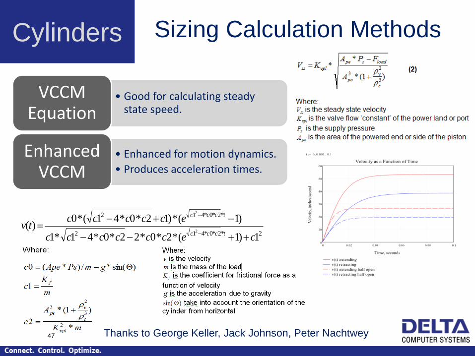
Cylinders Sizing Calculation Methods
• Good for calculating steady state speed.
VCCM Equation
• Enhanced for motion dynamics.
• Produces acceleration times.
Enhanced VCCM
2*2*0*412
*2*0*412
1)1(*2*0*22*0*41*1
)1(*)12*0*41(*0)(
2
2
cecccccc
eccccctv
tccc
tccc
Thanks to George Keller, Jack Johnson, Peter Nachtwey 47

Controlling Sloppy Systems Low Natural Frequency
Mass
Spring absorbs
energy
during acceleration,
then releases it
Forc
e
48
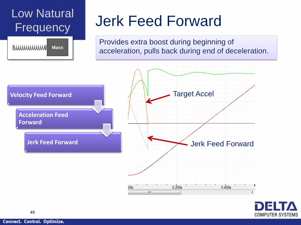
Low Natural
Frequency Jerk Feed Forward
Provides extra boost during beginning of
acceleration, pulls back during end of deceleration.
Velocity Feed Forward
Acceleration Feed Forward
Jerk Feed Forward
Mass
Target Accel
Jerk Feed Forward
49

Double Differential Gain Low Natural Frequencies require extra control f the
acceleration. Double Differential Gain.
Low Natural
Frequency
Mass
Target
Accel
Actual
Accel
50

Double Differential Gain
Quantization Noise
Low Natural
Frequency
Mass
51

Observer Calculates actual acceleration based on the
mathematical system model.
This Actual Acceleration is very clean, allowing the
double differential gain to be used.
Low Natural
Frequency
Mass
Output Filter is also
possible.
It filters the result of the
Double Differential
Gain, does not filter
actual acceelration.
52

Prerequisites to using
Double-Differential Gain
Low Natural
Frequency
Mass
• High resolution feedback
• High response, linear valve
53

Cylinders Real-Life Cylinder Example Sawmill
• A number of years ago, sawmill OEM needed
assistance tuning during new sawmill startup
• Delta suggested increasing cylinder bore to
achieve proper stiffness
• OEM replaced cylinders
Cost: Several $100,000
• Now, with advanced tuning, it is possible to
control smaller cylinders.
• Higher-order tuning is complex, so should be
approached with caution.
54

Cylinders Real-Life Cylinder Example Sheet metal brake
• Customer designed brake with one cylinder on
either end, one valve in middle. Approx. 6 ft hose
to each.
• Customer requested assistance tuning
• After 6 hours of tuning, met specs. This required
Double-differential gain.
• Pros: customer achieved competitive machine
price
• Cons: Difficult tuning, maintenance tuning
requires great expertise.
55
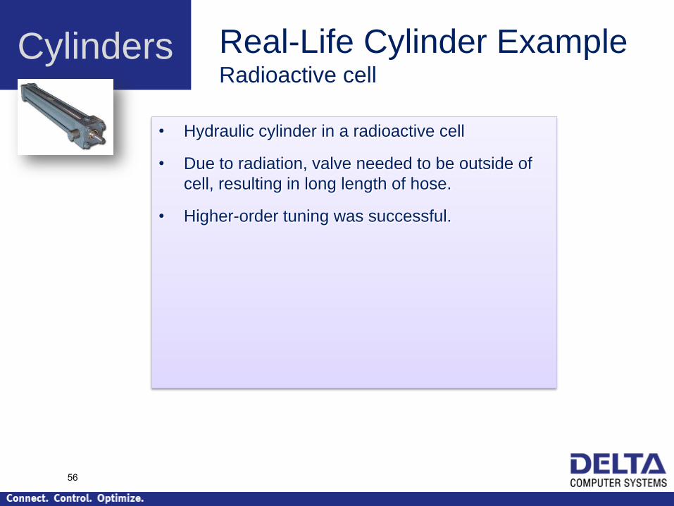
Cylinders Real-Life Cylinder Example Radioactive cell
• Hydraulic cylinder in a radioactive cell
• Due to radiation, valve needed to be outside of
cell, resulting in long length of hose.
• Higher-order tuning was successful.
56

Cylinders Real-Life Cylinder Example Large Pool
• In House of Dancing Waters in Macau, hydraulic
cylinders were in large pool.
• Valves needed to be outside of pool, resulting in
long length of hose.
• Higher-order tuning was successful.
57

Summary
Proper hydraulic design saves time
and money
Real-life demands may require compromise
Modern motion controller features
compensate for design deficiencies
58

Summary
1 Problem
Many Problems
• Undersized Cylinder or remote valve
• Poor Valve
• Noisy Feedback
59