advanced foundation engineering - nptelnptel.ac.in/courses/105108069/mod03/lec03.pdf · advanced...
TRANSCRIPT
1
Advanced Foundation Engineering
2013
Prof.T.G. Sitharam Indian Institute of Science, Bangalore

2
CHAPTER 3: COMBINED FOOTING AND RAFT FOUNDATION
3.1 INTRODUCTION
3.2 MAT FOUNDATION IN SAND
3.3 MAT FOUNDATION IN CLAY
3.4 RIGID AND ELASTIC FOUNDATION
3.5 SAFE BEARING PRESSURES FOR MAT FOUNDATIONS ON SAND AND CLAY
3.5.1 Mats on Sand
3.5.2 Mats on Clay
3.6 ECCENTRIC LOADING
3.6.1 PROPORTIONING OF CANTILEVER FOOTING
3.7 DESIGN OF COMBINED FOOTINGS BY RIGID METHOD (CONVENTIONAL METHOD)
3.8 DESIGN OF COMBINED FOOTINGS
3.9 DESIGN OF MAT FOUNDATION BY RIGID METHOD
3.10 DESIGN OF COMBINED FOOTINGS BY ELASTIC LINE METHOD
3.11 DESIGN OF MAT FOUNDATIONS BY ELASTIC PLATE METHOD
3.12 FLOATING FOUNDATION
3.12.1 General Consideration
3.12.2 Problems to be Considered in the Design of a Floating Foundation
3.13 APPROXIMATE DESIGN OF RAFT FOUNDATIONS
3.14 RECTANGULAR COMBINED FOOTINGS

3
Chapter 3
Combined Footing and Raft Foundation
3.1 Introduction
In chapter 2 we considered the common methods of transmitting loads to subsoil
through spread footings carrying single column loads. In this chapter we consider the following
types of foundations:
1. Cantilever footings
2. Combined footings
3. Mat foundations
When a column is near or right next to a property limit, a square or rectangular
footing concentrically loaded under the column would extend into the adjoining property. If the
adjoining property is a public side walk or alley, local building codes may permit such footings
to project into public property. But when the adjoining property is privately owned, the
footings must be constructed within the property. In such cases, there are three alternatives
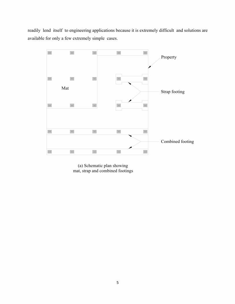
which are illustrated in Fig. 3.1(a). These are
(1) Cantilever footing:
A cantilever or strap footing normally comprises two footings connected by a beam
called a strap. A strap footing is a special case of a combined footing.
(2) Combined footing:
A combined footing is a long footing supporting two or more columns in one row.
(3) Mat or raft foundations:
A mat or raft foundation is a large footing, usually supporting several columns in two or
more rows.
The choice between these types depends primarily upon the relative cost. In the majority of
cases, mat foundations are normally used where the soil has low bearing capacity and where the
4
total area occupied by individual footings is not less than 50 per cent of the loaded area of the
building. When the distances between the columns and the loads carried by each column are not
equal, there will be eccentric loading. The effect of eccentricity is to increase the base pressure
on the side of eccentricity and decrease it on the opposite side. The effect of eccentricity on the
base pressure of rigid footings is also considered here.
3.2 Mat Foundation in Sand
Experience indicates that the ultimate bearing capacity of a mat foundation on cohesionless soil
is much higher than that of individual footings of lesser width. With the increasing width of the
mat, or increasing relative density of the sand, the ultimate bearing capacity increases rapidly.
Hence, the danger that a large mat may break into a sand foundation is too remote to require
consideration. On account of the large size of mats the stresses in the underlying soil are
likely to be relatively high to a considerable depth. Therefore, the influence of local
loose pockets distributed at random throughout the sand is likely to be about the same
beneath all parts of the mat and differential settlements are likely to be smaller than those
of a spread foundation designed for the same soil pressure. The methods of calculating the
ultimate bearing capacity dealt with in Chapter 2 are also applicable to mat foundations.
3.3 Mat Foundation in Clay
The net ultimate bearing capacity that can be sustained by the soil at the base of a mat on a deep
deposit of clay or plastic silt may be obtained in the same manner as for footings on clay
discussed in Chapter 2. However, by using the principle of flotation, the pressure on the base of
the mat that induces settlement can be reduced by increasing the depth of the foundation. A brief
discussion on the principle of flotation is dealt with in this chapter.
3.4 Rigid and Elastic Foundation
The conventional method of design of combined footings and mat foundations is to assume
the foundation as infinitely rigid and the contact pressure is assumed to have a planar
distribution. In the case of an elastic foundation, the soil is assumed to be a truly elastic solid
obeying Hooke's law in all directions. The design of an elastic foundation requires knowledge of
the subgrade reaction which is briefly discussed here. However, the elastic method does not
5
readily lend itself to engineering applications because it is extremely difficult and solutions are
available for only a few extremely simple cases.
Combined footing
(a) Schematic plan showing mat, strap and combined footings
Strap footing
Property
Mat
6
Fig 3.1 (a) Types of footings; (b) Beams on compressible subgrade
3.5 Safe Bearing Pressures for Mat Foundations on Sand and Clay
3.5.1 Mats on Sand
Because the differential settlements of a mat foundation are less than those of a spread
foundation designed for the same soil pressure, it is reasonable to permit larger safe soil
pressures on a raft foundation. Experience has shown that a pressure approximately twice as
great as that allowed for individual footings may be used because it does not lead to detrimental
differential settlements. The maximum settlement of a mat may be about 50 mm (2 in)
instead of 25 mm as for a spread foundation.
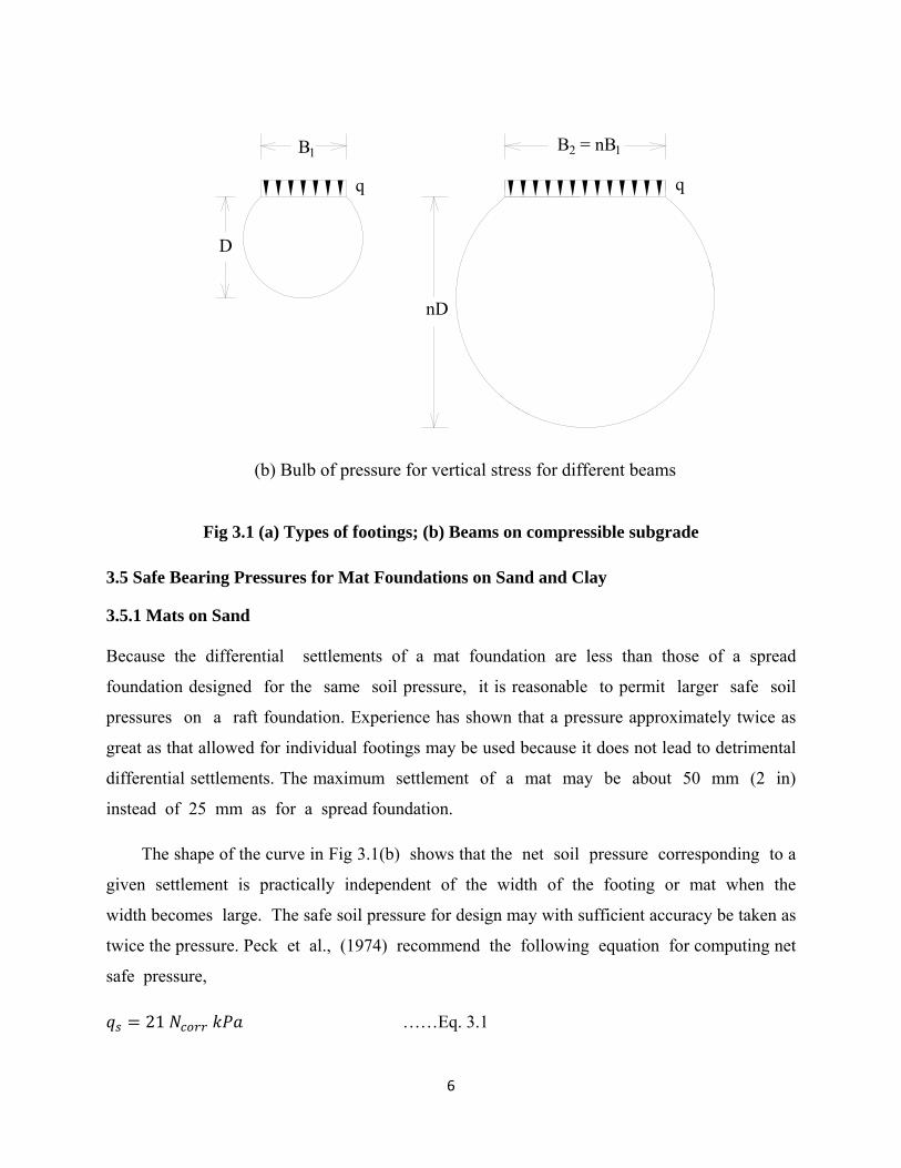
The shape of the curve in Fig 3.1(b) shows that the net soil pressure corresponding to a
given settlement is practically independent of the width of the footing or mat when the
width becomes large. The safe soil pressure for design may with sufficient accuracy be taken as
twice the pressure. Peck et al., (1974) recommend the following equation for computing net
safe pressure, 𝑞 = 21 𝑁 𝑘𝑃𝑎 ……Eq. 3.1
q
(b) Bulb of pressure for vertical stress for different beams
B1
D
q
B2 = nB1
nD

7
for 5 < 𝑁 < 50 where, N = SPT value corrected for energy, overburden pressure and field procedures.
Peck et al., (1974) also recommend that the qs values as given by Eq. 3.1 may be
increased somewhat if bedrock is encountered at a depth less than about one half the width of the
raft. The value of N to be considered is the average of the values obtained up to a depth equal to
the least width of the raft. If the average value of N after correction for the influence of
overburden pressure and dilatancy is less than about 5, Peck et al., say that the sand is generally
considered to be too loose for the successful use of a raft foundation. Either the sand should be
compacted or else the foundation should be established on piles or piers.
The minimum depth of foundation recommended for a raft is about 2.5 m below
the surrounding ground surface. Experience has shown that if the surcharge is less than this
amount, the edges of the raft settle appreciably more than the interior because of a lack of
confinement of the sand.
3.5.2 Mats on Clay
‘qnu’ is the net bearing capacity at the elevation of the base of the raft in excess of that exerted
by the surrounding surcharge. By increasing the depth of excavation, the pressure that
can safely be exerted by the building is correspondingly increased. This aspect of the
problem is considered further in Section 3.10 in floating foundation. As for footings on clay,
the factor of safety against failure of the soil beneath a mat on clay should not be less than 3
under normal loads, or less than 2 under the most extreme loads. The net safe pressure should be
decided on the basis of the permissible settlement.
3.6 Eccentric Loading
When the resultant of loads on a footing does not pass through the center of the footing, the
footing is subjected to what is called eccentric loading. The loads on the footing may be vertical
or inclined. If the loads are inclined it may be assumed that the horizontal component is resisted
by the frictional resistance offered by the base of the footing. The vertical component in such a
case is the only factor for the design of the footing.
3.6.1 Proportioning of Cantilever Footing
8
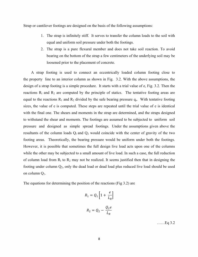
Strap or cantilever footings are designed on the basis of the following assumptions:
1. The strap is infinitely stiff. It serves to transfer the column loads to the soil with
equal and uniform soil pressure under both the footings.
2. The strap is a pure flexural member and does not take soil reaction. To avoid
bearing on the bottom of the strap a few centimeters of the underlying soil may be
loosened prior to the placement of concrete.
A strap footing is used to connect an eccentrically loaded column footing close to
the property line to an interior column as shown in Fig. 3.2. With the above assumptions, the
design of a strap footing is a simple procedure. It starts with a trial value of e, Fig. 3.2. Then the
reactions Rl and R2 are computed by the principle of statics. The tentative footing areas are
equal to the reactions R1 and R2 divided by the safe bearing pressure qs. With tentative footing
sizes, the value of e is computed. These steps are repeated until the trial value of e is identical
with the final one. The shears and moments in the strap are determined, and the straps designed
to withstand the shear and moments. The footings are assumed to be subjected to uniform soil
pressure and designed as simple spread footings. Under the assumptions given above the
resultants of the column loads Ql and Q2 would coincide with the center of gravity of the two
footing areas. Theoretically, the bearing pressure would be uniform under both the footings.
However, it is possible that sometimes the full design live load acts upon one of the columns
while the other may be subjected to a small amount of live load. In such a case, the full reduction
of column load from Rl to R2 may not be realized. It seems justified then that in designing the
footing under column Q2, only the dead load or dead load plus reduced live load should be used
on column Q1.
The equations for determining the position of the reactions (Fig 3.2) are
𝑅 = 𝑄 1 + 𝑒𝐿
𝑅 = 𝑄 − 𝑄 𝑒𝐿
……Eq 3.2

9
where Rl and R2 = reactions for the column loads Ql and Q2 respectively
e = distance of Rl from Ql 𝐿 = distance between Rl and R2.
Fig 3.2 Principles of cantilever or strap footing design
3.7 Design of Combined Footings by Rigid Method (Conventional Method)
The rigid method of design of combined footings assumes that
1. The footing or mat is infinitely rigid, hence, the deflection of the footing or
mat does not influence the pressure distribution,
2. The soil pressure is distributed in a straight line or a plane surface such that the
centroid of the soil pressure coincides with the line of action of the resultant
force of all the loads acting on the foundation.
3.8 Design of Combined Footings
Two or more columns in a row joined together by a stiff continuous footing form a
combined footing as shown in Fig. 3.3(a). The procedure of design for a combined footing is as
follows:
10
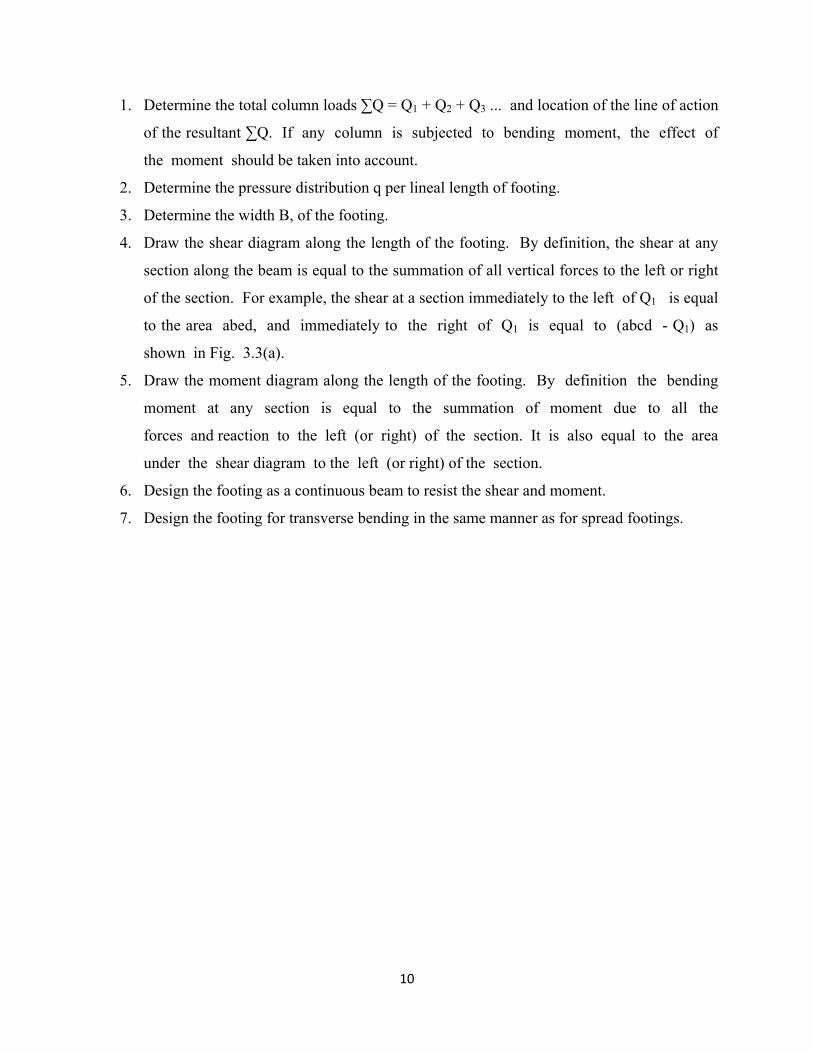
1. Determine the total column loads ∑Q = Q1 + Q2 + Q3 ... and location of the line of action
of the resultant ∑Q. If any column is subjected to bending moment, the effect of
the moment should be taken into account.
2. Determine the pressure distribution q per lineal length of footing.
3. Determine the width B, of the footing.
4. Draw the shear diagram along the length of the footing. By definition, the shear at any
section along the beam is equal to the summation of all vertical forces to the left or right
of the section. For example, the shear at a section immediately to the left of Q1 is equal
to the area abed, and immediately to the right of Q1 is equal to (abcd - Q1) as
shown in Fig. 3.3(a).
5. Draw the moment diagram along the length of the footing. By definition the bending
moment at any section is equal to the summation of moment due to all the
forces and reaction to the left (or right) of the section. It is also equal to the area
under the shear diagram to the left (or right) of the section.
6. Design the footing as a continuous beam to resist the shear and moment.
7. Design the footing for transverse bending in the same manner as for spread footings.

11
Fig 3.3 Combined or Trapezoidal footing design
It should be noted here that the end column along the property line may be connected to the
interior column by a rectangular or trapezoidal footing. In such a case no strap is required and
both the columns together will be a combined footing as shown in Fig. 3.3b. It is necessary
that the center of area of the footing must coincide with the center of loading for the
pressure to remain uniform.
3.9 Design of Mat Foundation by Rigid Method
In the conventional rigid method the mat is assumed to be infinitely rigid and the bearing
pressure against the bottom of the mat follows a planar distribution where the centroid of
12
the bearing pressure coincides with the line of action of the resultant force of all loads acting
on the mat. The procedure of design is as follows:
1. The column loads of all the columns coming from the superstructure are calculated as per
standard practice. The loads include live and dead loads.
2. The line of action of the resultant of all the loads is found. However, the weight of the
mat is not included in the structural design of the mat because every point of the
mat is supported by the soil under it, causing no flexural stresses.
3. Calculate the soil pressure at desired locations by the use of Eq. 3.3
𝑞 = 𝑄𝐴 ± 𝑄 𝑒𝐼 𝑥 ± 𝑄 𝑒𝐼 𝑦
……Eq 3.3
where 𝑄 = ∑ 𝑄= total load on the mat
A = total area of the mat
x, y = coordinates of any given point on the mat with respect to the x
andy axes passing through the centroid of the area of the mat 𝑒 , 𝑒 = eccentricities of the resultant force 𝐼 , 𝐼 = moments of inertia of the mat with respect to the x and y axes
respectively.
4. The mat is treated as a whole in each of two perpendicular directions. Thus the total shear
force acting on any section cutting across the entire mat is equal to the arithmetic sum of
all forces and reactions (bearing pressure) to the left (or right) of the section. The total
bending moment acting on such a section is equal to the sum of all the moments to the
left (or right) of the section.
3.10 Design of Combined Footings by Elastic Line Method

13
The relationship between deflection, y, at any point on an elastic beam and the
corresponding bending moment M may be expressed by the equation
𝐸𝐼 𝑑 𝑦𝑑𝑥 = 𝑀
……Eq 3.4
The equations for shear V and reaction q at the same point may be expressed as
𝐸𝐼 𝑑 𝑦𝑑𝑥 = 𝑉
……Eq 3.5
𝐸𝐼 𝑑 𝑦𝑑𝑥 = 𝑞
……Eq 3.6
where, x is the coordinate along the length of the beam.
From basic assumption of an elastic foundation 𝑞 = −𝑦𝐵𝑘
where, B = width of the footing, 𝑘 = coefficient of subgrade reaction
Substituting for q, Eq 3.6 may be written as
𝐸𝐼 𝑑 𝑦𝑑𝑥 = −𝑦𝐵𝑘
……Eq 3.7
The classical solutions of Eq. (3.7) being of closed form, are not general in their
application. Hetenyi (1946) developed equations for a load at any point along a beam.
The development of solutions is based on the concept that the beam lies on a bed of
14
elastic springs and is based on Winkler's hypothesis. As per this hypothesis, the reaction at
any point on the beam depends only on the deflection at that point. Methods are also
available for solving the beam-problem on an elastic foundation by the method of finite
differences (Malter, 1958). The finite element method has been found to be the most efficient of
the methods for solving beam-elastic foundation problem. Computer programs are available for
solving the problem. Since all the methods mentioned above are quite involved, they are
not dealt with here. Interested readers may refer to Bowles (1996).
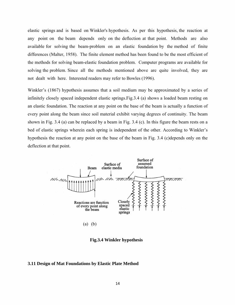
Winkler’s (1867) hypothesis assumes that a soil medium may be approximated by a series of
infinitely closely spaced independent elastic springs.Fig.3.4 (a) shows a loaded beam resting on
an elastic foundation. The reaction at any point on the base of the beam is actually a function of
every point along the beam since soil material exhibit varying degrees of continuity. The beam
shown in Fig. 3.4 (a) can be replaced by a beam in Fig. 3.4 (c). In this figure the beam rests on a
bed of elastic springs wherein each spring is independent of the other. According to Winkler’s
hypothesis the reaction at any point on the base of the beam in Fig. 3.4 (c)depends only on the
deflection at that point.
(a) (b)
Fig.3.4 Winkler hypothesis
3.11 Design of Mat Foundations by Elastic Plate Method

15
Of the many methods that are available for the design of mat-foundations, the one that is very
much in use is the finite difference method. This method is based on the assumption that the
subgrade can be substituted by a bed of uniformly distributed coil springs with a spring
constant ks called the coefficient of subgrade reaction. The finite difference method uses the
fourth order differential equation.
∇ 𝑤 = … Eq 3.8
where, ∇ 𝑤 = + 2 +
q = subgrade reaction per unit area 𝑘 = coefficient of subgrade reaction
w = deflection
D = rigidity of the mat = ( ) E = modulus of elasticity of the material of the footing
t = thickness of mat 𝜇 = Poisson’s ratio.
Eq. 3.8 may be solved by dividing the mat into suitable square grid elements, and writing
difference equations for each of the grid points. By solving the simultaneous equations so
obtained the deflections at all the grid points are obtained. The equations can be solved rapidly
with an electronic computer. After the deflections are known, the bending moments are
calculated using the relevant difference equations. Interested readers may refer to Teng (1969) or
Bowles (1996) for a detailed discussion of the method.
3.12 Floating Foundation
3.12.1 General Consideration
A floating foundation for a building can be defined as a foundation in which the weight of
the building is approximately equal to the full weight which includes water of the soil removed
from the site of the building. With reference to Fig 3.5 this principle of flotation may be
explained. Fig. 3.5(a) shows a horizontal ground surface with water table at a depth dw below
16
the ground surface. Fig. 3.5(b) shows an excavation made in the ground to a depth D
where, D > dw and Fig. 3.5(c) shows a structure built in the excavation and completely filling
it. If the weight of the building is equal to the weight of the soil and water removed from
the excavation, then it is clear that the total vertical pressure in the soil below depth D
in Fig. 3.5(c) is the same as in Fig. 3.5(a) before excavation. Since there is no change in the
water level, the neutral pressure and the effective pressure remain unchanged. If we could
move from Fig. 3.5(a) to Fig. 3.5(c) without coming across the intermediate case of 3.5(b), the
building in Fig. 3.5(c) would not settle at all, since an increase in effective vertical pressure
cause settlements. Principle of a floating foundation: An exact balance of weight removed
against weight imposed. The obtained result is zero settlement of the building.
However, it may be noted, that we cannot jump from the stage shown in Fig. 3.5(a) to the stage
in Fig. 3.5(c) without passing stage 3.5(b). This is because the excavation stage of the building
is the critical stage.
There may occur cases where we cannot have a fully floating foundation. The foundations of this
type are called “partly compensated foundations” (as against fully compensated or fully floating
foundations).
While dealing with floating foundations, it is important that we consider the following two types
of soils.
Type 1: The foundation soils are of such strength that shear failure of soil will not occur under
the building load. But the settlements, differential settlements in particular are so large that they
constitute the failure of the structure. In such cases a floating foundation is used to reduce
settlements to an acceptable value.
Type 2: The shear strength of the foundation soil is so low that rupture of the soil would occur if
the building were to be founded at ground level. At a reasonable depth, in the absence of a strong
layer the building can only be built on a floating foundation. This reduces the shear stresses to an
acceptable value. Solving this problem helps solve the settlement problem. In the above
mentioned cases, a rigid raft or box type of foundation is required for the floating foundation as
shown in Fig. 3.4(d)

17
Fig 3.5 Principles of floating foundation; and a typical rigid raft foundation
3.12.2 Problems to be considered in the Design of a Floating Foundation
The following problems are to be considered during the design and construction stage of a
floating foundation.
1. Excavation
The excavation for the foundation has to be done with care. The sides of the excavation
should suitably be supported by sheet piling, soldier piles and timber lagging or some
other standard method.
2. Dewatering
Dewatering will be necessary when excavation has to be taken below the water table
level. Care has to be taken to see that the adjoining structures are not affected due to the
lowering of the water table.
18
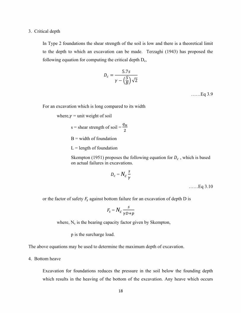
3. Critical depth
In Type 2 foundations the shear strength of the soil is low and there is a theoretical limit
to the depth to which an excavation can be made. Terzaghi (1943) has proposed the
following equation for computing the critical depth Dc,
𝐷 = 5.7𝑠𝛾 − 𝑆𝐵 √2
……Eq 3.9
For an excavation which is long compared to its width
where,𝛾 = unit weight of soil
s = shear strength of soil =
B = width of foundation
L = length of foundation
Skempton (1951) proposes the following equation for 𝐷 , which is based on actual failures in excavations. 𝐷 = 𝑁
……Eq 3.10
or the factor of safety 𝐹 against bottom failure for an excavation of depth D is 𝐹 = 𝑁
where, Nc is the bearing capacity factor given by Skempton,
p is the surcharge load.
The above equations may be used to determine the maximum depth of excavation.
4. Bottom heave
Excavation for foundations reduces the pressure in the soil below the founding depth
which results in the heaving of the bottom of the excavation. Any heave which occurs

19
will be reversed and appear as settlement during the construction of the foundation and
the building. Though heaving of the bottom of the excavation cannot be avoided it can
be minimized to a certain extent. There are three possible causes of heave:
1. Elastic movement of the soil as the existing overburden pressure is removed.
2. A gradual swelling of soil due to the intake of water if there is some delay in
placing the foundation on the excavated bottom of the foundation.
3. Plastic inward movement of the surrounding soil.
The last movement of the soil can be avoided by providing proper lateral support
to the excavated sides of the trench. Heaving can be minimized by phasing out excavation
in narrow trenches and placing the foundation soon after excavation. It can be minimized
by lowering the water table during the excavation process. Friction piles can also be used to
minimize the heave. The piles are driven either before excavation commences or when the
excavation is at half depth and the pile tops are pushed down to below foundation level. As
excavation proceeds, the soil starts to expand but this movement is resisted by the upper part of
the piles which go into tension. The heave is prevented or very much reduced. It is only a
practical and pragmatic approach that would lead to a safe and sound settlement free floating (or
partly floating) foundation.
3.13 Approximate Design of Raft Foundations
The design of raft foundations from a soil mechanics point of view is relatively simple
and is similar to that of isolated footings. However the following points are to be noted.
1) Rafts on Cohesionless soil
The bearing capacity of raft foundations on sand is always very high due to size
effects. Differential settlement governs the design but this is determined by the strength
and stiffness of the raft structure and is very difficult to assess. The structural design of a
raft is quite a difficult procedure due to the interaction between contact pressure
distribution and deflected shape of the structure.
However the flexural action of a raft serves to reduce the differential settlements
considerably i.e., if the raft is rigid (as for a grain silo) there will be zero differential
20
settlement, though tilting or uneven settlement of the structure as a whole may occur. The
normal design rule is therefore to allow twice the total settlement allowed for isolated
footings. This procedure, is, however quite empirical. The pressure which produces
settlement is the net building pressure since the excavated soil is not replaced.
2) Rafts on Saturated Cohesive soil
It was noted earlier that, contrary to sands, the allowable bearing pressure for
structures on clay does not increase with foundation size. Consequently, rafts
founded on saturated clay have to be checked for both bearing capacity and
settlement since either may govern the design.
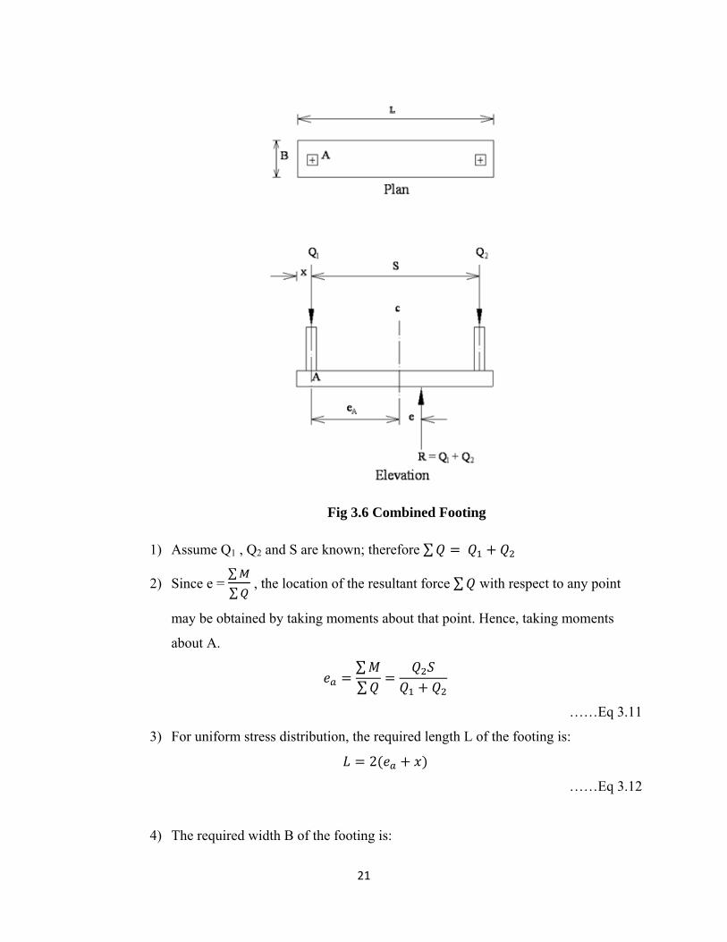
3.14 Rectangular Combined Footings Space restrictions or architectural features may require one footing to carry at
least two column loads as shown in Fig 3.6 Conventional design and analysis are based
on the assumption that the footing is infinitely stiff and that stress distribution on the base
of the footing is planar.
21
Fig 3.6 Combined Footing
1) Assume Q1 , Q2 and S are known; therefore ∑ 𝑄 = 𝑄 + 𝑄
2) Since e = ∑∑ , the location of the resultant force ∑ 𝑄 with respect to any point
may be obtained by taking moments about that point. Hence, taking moments
about A. 𝑒 = ∑ 𝑀∑ 𝑄 = 𝑄 𝑆𝑄 + 𝑄
……Eq 3.11
3) For uniform stress distribution, the required length L of the footing is: 𝐿 = 2(𝑒 + 𝑥)
……Eq 3.12
4) The required width B of the footing is:
22
𝐵 = 𝑄 + 𝑄𝑞 × 𝐿
……Eq 3.13
The values of B and L are usually rounded to a convenient value and the actual
values of qmax and qmin are computed from
𝑞 = ∑ 𝑄𝐵 × 𝐿 1 + 6𝑒𝐿
……Eq 3.14
where, e = eccentricity, with respect to the centre of gravity of the footing
of the resultant column load.