advanced features and application design challenges
TRANSCRIPT

© Copyright 2009 Performance Motion Devices, Inc. All Rights Reserved.
Performance Motion Devices
MOTION CONTROL CARDS FOR MACHINE DESIGN
Advanced Features and Application Design Challenges
Erlendur Kristjansson

© Copyright 2009 Performance Motion Devices, Inc. All Rights Reserved.

© Copyright 2009 Performance Motion Devices, Inc. All Rights Reserved.
Table of Contents Abstract ................................................................................................................................................................................ 4 Introduction ........................................................................................................................................................................... 5 Motion Control Card Basics .............................................................................................................................................. 5
Recent Developments ..................................................................................................................................................... 6 Advanced Features ............................................................................................................................................................ 7
Card Programmability .................................................................................................................................................. 8 Programming Language 8 Proprietary Command Language 9 C/C++ 9 IEC 61131-3 10 Summary 10
Communication Options .............................................................................................................................................. 10 Physical Requirements 11
Form Factor & Architecture ............................................................................................................................................ 11 Form Factor................................................................................................................................................................... 11
PCI-bus 11 PC/104 12 Stand-alone 12
System Architecture ..................................................................................................................................................... 13 PC-bus Cards 13 Stand-alone Cards 13
Design Considerations ..................................................................................................................................................... 14 System Host Code Development .............................................................................................................................. 14 Card Code Development .......................................................................................................................................... 15 Other System Components ........................................................................................................................................ 15
Interconnect Board 15 Amplifiers & Motors 15 Cabling 16
Type of Application ........................................................................................................................................................ 16 PCI-bus Card ................................................................................................................................................................ 16 PC/104 Card .............................................................................................................................................................. 16 Stand-alone Card ....................................................................................................................................................... 16
Application Examples ..................................................................................................................................................... 17 PCI Card Example – 3D Printer ............................................................................................................................... 17 PC/104 Card Example – Table Top Test Equipment .......................................................................................... 17 Stand-alone Card Example – Pick & Place Machine .......................................................................................... 17
Conclusion .......................................................................................................................................................................... 18
© Copyright 2009 Performance Motion Devices, Inc. All Rights Reserved.
Page 4
Abstract The purpose of this paper is to illustrate how OEM machine designers can benefit from motion control cards in their design.
This paper looks at the different motion control card form factors, their fit into different machine require-ments, and how they affect the outcome of a machine design. This paper also examines the interaction be-tween the motion cards and the system architectures to illustrate design trade-offs. Examples of machines that benefit from each form factor include a 3D printer, table top test equipment and a three-stage pick and place assembly line.
Topics include:
card form factor
advanced features
board-level programming of cards
communication options and affect on system architecture
design consideration when developing machines using motion control cards
Company Contact Information Performance Motion Devices, Inc. 55 Old Bedford Road Lincoln, MA 01773 USA Phone: 781.674.9860 Fax: 781.674.9861
Website: www.pmdcorp.com
© Copyright 2009 Performance Motion Devices, Inc. All Rights Reserved.
Page 5
Motion Control Cards for Machine Design
Introduction Motion control cards are a popular way to perform motion control in applications such as light manufactur-ing, laboratory machines, and instrumentation. The main reason for this is their unique form factors, which have mainly been driven by the computer platform they work on. This has started to change recently with the introduction of the stand-alone form factor.
We will start by looking at the basic functionality of motion control cards and then move to the newer and more advanced features like programmability and communication. From there we will look at how the form factor affects the overall machine system architecture and the design considerations that follow. Final-ly, we will go through what applications benefit from each form factor/architecture and analyze some ex-ample applications.
Motion Control Card Basics Originally, motion control cards were PC plug-in cards that allowed the use of a standard PC platform, mainly MS-DOS. This was, and still is, a very attractive solution as the PC computational performance has increased exponentially while the cost has been dropping rapidly. The initial cards were ISA-bus based. As time went on EISA- and PCI-bus solutions appeared, and even some industrial bus solutions like VME. With improvements in semiconductor technology, smaller PC motherboards became possible and the PC/104 standard was created around the ISA-bus, to support the use of a PC-based control system in smaller physical spaces. The standard card usually supports 1 to 4 axes, but there are some that support up to 32 axes.
A motion control card system has the following components:
- PC motherboard - Motion control card - Optional I/O card - Interconnect card - Chassis (mandatory for PCI based motherboards)
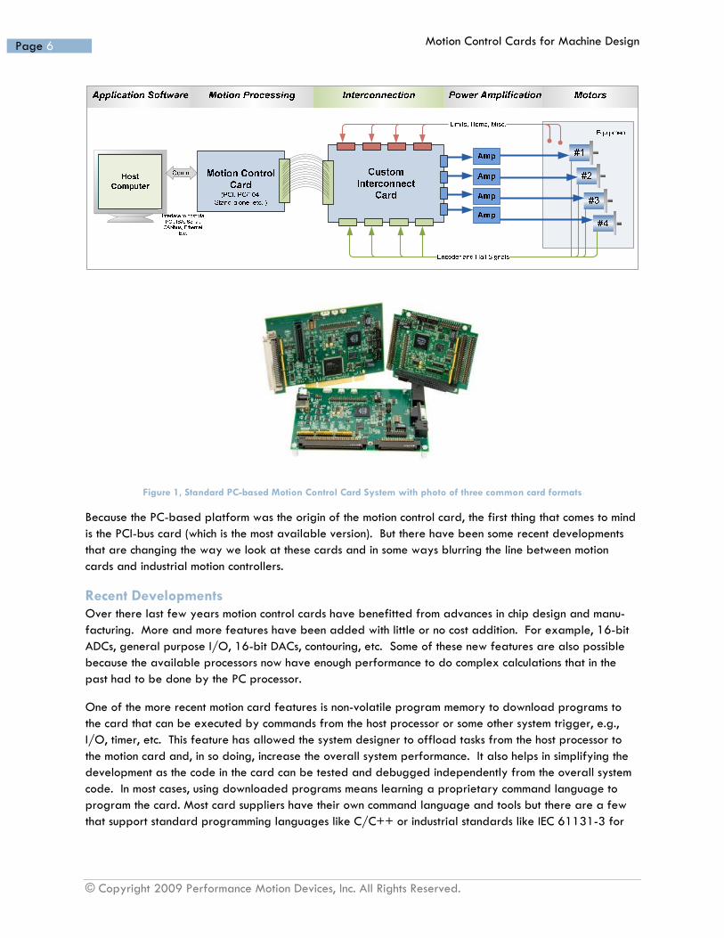
Figure 1 shows a typical system. The interconnect card is a very unique motion control card feature. The card’s signals usually come through a high density connector that needs to be split up into the various sig-nals for each axis and that is where the interconnect card comes into the picture.
Motion Control Cards for Machine Design
© Copyright 2009 Performance Motion Devices, Inc. All Rights Reserved.
Page 6
Figure 1, Standard PC-based Motion Control Card System with photo of three common card formats
Because the PC-based platform was the origin of the motion control card, the first thing that comes to mind is the PCI-bus card (which is the most available version). But there have been some recent developments that are changing the way we look at these cards and in some ways blurring the line between motion cards and industrial motion controllers.
Recent Developments Over there last few years motion control cards have benefitted from advances in chip design and manu-facturing. More and more features have been added with little or no cost addition. For example, 16-bit ADCs, general purpose I/O, 16-bit DACs, contouring, etc. Some of these new features are also possible because the available processors now have enough performance to do complex calculations that in the past had to be done by the PC processor.
One of the more recent motion card features is non-volatile program memory to download programs to the card that can be executed by commands from the host processor or some other system trigger, e.g., I/O, timer, etc. This feature has allowed the system designer to offload tasks from the host processor to the motion card and, in so doing, increase the overall system performance. It also helps in simplifying the development as the code in the card can be tested and debugged independently from the overall system code. In most cases, using downloaded programs means learning a proprietary command language to program the card. Most card suppliers have their own command language and tools but there are a few that support standard programming languages like C/C++ or industrial standards like IEC 61131-3 for

Motion Control Cards for Machine Design
© Copyright 2009 Performance Motion Devices, Inc. All Rights Reserved.
Page 7
card programming using third-party tools. We shall discuss all of these options further in a subsequent sec-tion.
Another recent feature is the use of Ethernet as the host communication interface to the card and therefore removing the need for a PC-bus and PC motherboard. Data rates of up to 100 Mbps (soon to be 1 Gbps) combined with the capability of downloading programs to the card have allowed for a new form factor we call stand-alone. With the stand-alone card connected to the host over Ethernet, or some other high-speed serial network, you can now distribute your motion processing closer to the amplifiers and mo-tors and simplify your cabling. This is possible if your machine benefits from a distributed and/or modula-rized architecture.
Advanced Features Before we cover some of the more advanced features of motion cards, let’s quickly review what are consi-dered to be standard features in today’s cards. The following features are considered standard by the marketplace and should be available in any motion card considered for a modern application:
- 1- to 4-axis of motor command signals o The command signals can be one or more of the following:
Analog ±10V Pulse and direction PWM
DC Brush motor
Brushless DC motor
Stepper motor - Motion profile selection
o Trapezoidal, and/or velocity contouring - Control algorithms
o PID Position control Velocity control
- Incremental encoder feedback - Contouring
o At least 2D linear interpolation - Dedicated I/O
o Limit switches o Emergency stop o Enable
- General purpose I/O o 4-8 Digital I/O
Could be separate inputs and outputs o Analog inputs
- PC-bus host communications o PCI, ISA, PC/104, etc.
Motion Control Cards for Machine Design
© Copyright 2009 Performance Motion Devices, Inc. All Rights Reserved.
Page 8
Now that we have established what are considered standard features we can look at a list of desirable advanced features. Of course, this can be nearly infinite as suppliers will continue to add to it, so we will only list a few of the more important features.
- Programmability o Downloadable code to be executed by the processor on the card
- Motion profile selection o S-curve
- Control algorithms o Velocity/ acceleration feed-forward o Bi-quad filters
- Enhanced communication o Addition of high speed serial communications instead of or in addition to the PC-bus
Ethernet CANbus RS232/485 Etc.
- Advanced feedback technology o Absolute encoder
SSI EnDAT Sin/Cos Resolver
- Feature expansion port o 16- or 32-bit bus that allows the plug-in of daughter cards that add new fea-
tures/capabilities to the card - Stand-alone form factor
o Ability to operate remotely from a system host computer/processor
Let’s explore two of the most recent feature enhancements, programmability and communication in a bit more detail.
Card Programmability The ability to execute programs directly on the motion control card is a natural extension to the develop-ments in embedded technology over the last decade. With advances in non-volatile memory technology and MCUs/DSPs, the cost of creating a programmable platform has come down significantly. The question is not if, but rather how to implement this feature. Up to now most motion control card suppliers have re-lied on proprietary command languages with their own unique and often cryptic syntax. However, some suppliers have started to offer cards that support standard programming languages like C/C++ or the IEC 61131-3 standard for programming industrial control components.
Let’s look at the different programming architectures.
Programming Language What benefits does each programming language option give the system developer? What are the posi-tive and negative aspects of each? Let’s start by looking at the most common one first.

Motion Control Cards for Machine Design
© Copyright 2009 Performance Motion Devices, Inc. All Rights Reserved.
Page 9
Proprietary Command Language Creating your own command language makes a lot of sense for the makers of motion control cards. It avoids any need for a compiler and minimizes risk by limiting the flexibility of the command set to motion related functions, thus avoiding the creation of motion programs that adversely affect the user experience and the final result. It also allows them to optimize the language syntax to match the functionality of the card. With a proprietary command language, the manufacturer controls what the user can and cannot do. This minimizes risk when the user is writing programs. There is minimal risk of creating code that will crash the card processor. The only issue will be programming mistakes by the user that result in their system not functioning as expected.
This of course leads to the need for custom development tools, but even with this issue there is a benefit. The simplest way to implement a command language is to have it interpreted. Therefore, there is no need for a compiler and linker, which simplifies the development of the tools. The processor that is running the card needs to interpret each of the instructions and the more flexibility there is in the syntax, the more complicated the interpreter code will be. This will then impact the execution performance of the user code. Fortunately, as we mentioned earlier, the cost of processing power has been falling allowing for good per-formance with a relatively minimal cost increase.
From the user’s point of view, the custom command language is both good and bad. Because the command language has limited syntax it is fairly easy to learn and the programming tools are usually integrated with the motion control setup/tuning tools. On the other hand, the limits to the syntax also restrict what you can do in a program. Furthermore, the programs that you develop for cards from one vendor cannot be reused if you move to another vendor’s cards.
Even though the tradition has been to create custom command languages for motion cards, because it sim-plifies things for the manufacturer, there is a growing push from users to have standard and open pro-gramming languages. Therefore, some manufactures have begun to support standard programming lan-guages.
C/C++ Today C/C++ is the most commonly used programming language standard. With the improvement in compiler and linker technologies, the C-code has become nearly as optimized as pure assembly language code which makes it very fast and efficient. Also, the lower cost of program memory has made the need to squeeze code into a limited space less of a factor.
To allow the user to write C-code that runs on the card’s processor, there has to be an operating system (OS) running on the processor, just like in a PC. In most cases this is a real-time operating system (RTOS) that manages the different functionalities of the processor and possibly the card. As is the case with any application running on an OS, the user’s code utilizes OS function calls to access the different features the system offers to the user. The primary feature is the motion control system, but other features like commu-nication and data processing can also be accessed.
Developing programs for a motion control card using C/C++ is much simpler than for a PC. With C/C++ the customer can use advanced features like function calls, custom libraries, etc., which are normally not available with vendor-specific languages. However, this flexibility may open up the possibility of the user code accessing or corrupting other things in the OS and processor. To avoid this, the card makers have to set up the RTOS and development system in such a way as to help insure proper functionality. This is nor-
Motion Control Cards for Machine Design
© Copyright 2009 Performance Motion Devices, Inc. All Rights Reserved.
Page 10
mally done by restricting the function libraries that are made available to the user, and by limiting access to certain parts of the RTOS and processor.
Because the code is compiled for the processor that the RTOS is running on, the code is executing at the maximum speed of the processor and is not subject to the speed limitation that are inherent with inter-preted languages. This faster code execution time is often very important to the performance of multi-axis motion control systems.
IEC 61131-3 The international standard IEC 61131-3 was developed to improve the reusability of industrial control programs, by creating a standard programming interface that allows people with different backgrounds and skills to develop different parts of a program. Still, all the different parts adhere to a common struc-ture and work seamlessly together. Included in the standard is the definition of the language Sequential Function Charts (SFC), that are used to structure the program, and four interoperable languages: Instruction List (IL), Ladder Diagram (LD), Function Block Diagram (FBD) and Structured Text (ST). Furthermore, com-mon elements like variables and data types guarantee the proper interoperability between code modules.
The languages can be put into two groups; textual and graphical.
Textual: - Instruction List (similar to assembly code) - Structured Text (similar to Pascal and C/C++)
Graphical: - Ladder Diagram (graphical version of IL) - Function Block Diagram (graphical version of functions in C/C++)
All four languages are interchangeable allowing people with different programming skills to collaborate on the same project, maximize the use of staff, reuse code from previous projects and therefore shortening the design cycle/time to market.
Just like the C/C++ programs, the IEC 61131-3 programs need an OS to run under. Currently there are a variety of RTOS’ that support this. The use of this standard in cards is not as common as in other industrial solutions, though there are a few exceptions and the market place is changing in this direction. There are also some controllers that support one or two of the languages (most likely LD and IL).
Summary As can be seen from previous subsections, the different language solutions have their pluses and minuses, but as machine builders try to optimize their business, and therefore their design process, the use of stan-dard languages becomes more attractive. In the end it is a judgment call each design team has to make, based on the requirements they have to fulfill.
Communication Options As mentioned in the beginning of this paper, the original implementation of a motion control card was the ISA-bus based card that plugged into a PC. Since then there have been many changes in the PC world. Let’s look at what the old and new options are for communicating with motion control cards. The most common one is PCI-bus, which allows for a peak data transfer rate of 1Gbps (Giga bits per second = 1 billion bits per second). This is important if the host needs to communicate frequently to a card, and can be
Motion Control Cards for Machine Design
© Copyright 2009 Performance Motion Devices, Inc. All Rights Reserved.
Page 11
critical in machines with a large number of axes, e.g., 32-axis where it is important to minimize communica-tion time.
Another fairly common PC-bus architecture is the PC/104 standard, which was developed for embedded computing. Here the PC motherboard and add-on cards are designed to fit in a relatively small space. The bus is actually an ISA-bus, but there have been some extensions to the standard, which now include PCI and most recently PCI Express. The ISA-bus based version is the one that is most common for motion control cards. The throughput on the ISA-bus is limited to 133Mbps (Mega bits per second = Million bits per second), which is still a very high data rate for most motion control applications.
On the other hand, serial communication options have much more limited data bandwidth. For example, RS485 has theoretical max bandwidth of 35Mbps, though most actual implementations max out at 115kbps. CANbus can go up to 1Mbps, which is a very common implementation. The newest serial com-munication option is Ethernet. It is different than the other two in that it is not a multi-drop bus, and it has a much higher data bandwidth. The most common Ethernet versions currently used in industrial applications are 10BaseT and 100BaseT, 10Mbps and 100Mbps, respectively. Just like PCI, it is a standard computer interface and therefore has a very broad usage. Over the last two decades the PC platform has become very dominant in the industrial world and as such made Ethernet a logical choice for communications. Today the 1Gbps version has become the standard on PCs, so it will not be long until it will be standard in industrial equipment.
Physical Requirements There is a major difference between the two main communication options. Even though both are supporting the host-to-card communication, one has a physical requirement, i.e., the bus-based cards such as for ISA or PCI have to connect directly into the host PC motherboard. This has a tendency to limit the size of the ap-plication by making it difficult to distribute the processing amongst several cards.
Therefore it is important to take this into consideration when starting a new design. Which host communica-tion will fit the application without limiting any of the system requirements? At the end of this paper we will look at some examples that benefit from each of the different card form factors and the related host communication.
Form Factor & Architecture The selection of the communication bus will decide a lot about your form factor. Let us explore that further and see how it affects your overall system architecture.
Form Factor In the beginning of this paper we described the different form factors. Now we will look at each in more detail.
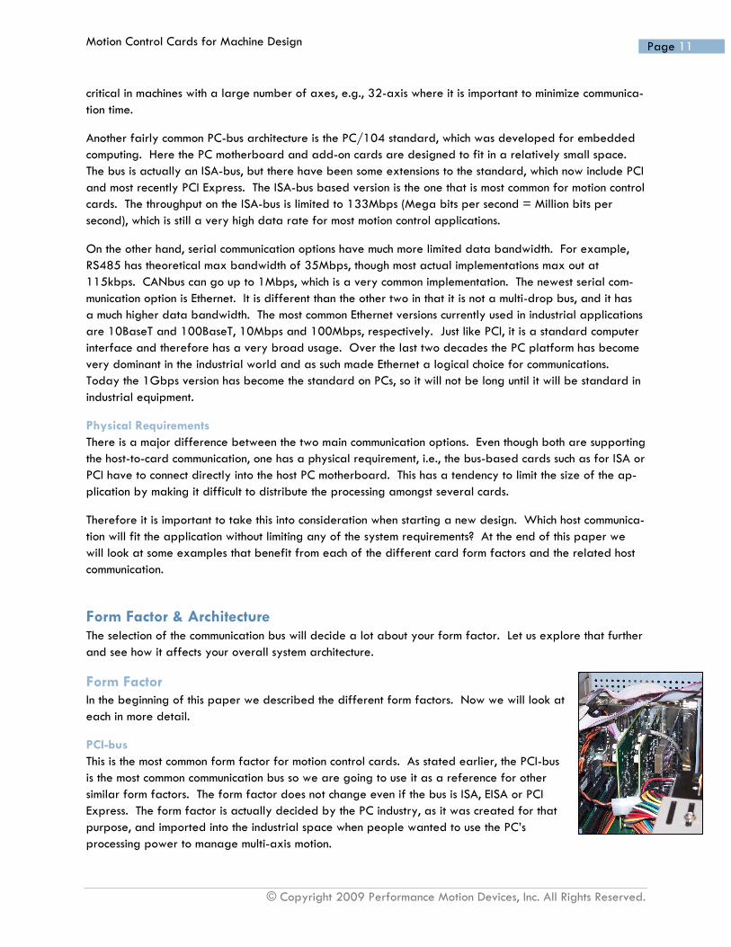
PCI-bus This is the most common form factor for motion control cards. As stated earlier, the PCI-bus is the most common communication bus so we are going to use it as a reference for other similar form factors. The form factor does not change even if the bus is ISA, EISA or PCI Express. The form factor is actually decided by the PC industry, as it was created for that purpose, and imported into the industrial space when people wanted to use the PC’s processing power to manage multi-axis motion.

Motion Control Cards for Machine Design
© Copyright 2009 Performance Motion Devices, Inc. All Rights Reserved.
Page 12
From a motion control system point of view, the benefits include very fast communication between host and motion card for higher system performance, standard PC motherboard form factor with a lower cost for a high performance host, and more of an off-the-shelf solution, which also contributes to a lower cost.
PC/104 This standard was created to move the PC into embedded solutions. One of the key features of embed-ded systems is smaller size. With the PC/104, a significant reduction in size is achieved with minimal im-pact on scalability and performance. PC/104 PC motherboards may not be available in the same variety as the standard PC motherboards, but the range still gives the equipment designers plenty to choose from to optimize both performance and cost.
The PC/104 form factor gives the designers the ability to stack their boards, motion controller and I/O boards, on top of the motherboard and in such a way to minimize the physical footprint of the system (see Figure 2). Even though most PC/104 motion control cards are based on the ISA-bus, the overall system performance is very high.
Figure 2, PC/104 board stacking
Stand-alone The stand-alone form factor is not yet based on any industrial standard; though there are a few suppliers that are using the DIN rail mount standard to define the available board size (see photos below). In reali-ty they are not “bus cards” since they do not mount into a chassis, but rather open printed circuit boards (PCBs) that the user can mount into a box or cabinet. In most cases the cards are about the same size as a PCI without the bus connector, in the range of 4”×6” (~100 mm × 150 mm).
The main benefit of the stand-alone form factor is that it allows cards to be remotely mounted in a ma-chine, rather than requiring that they be directly mounted into the PC motherboard. Furthermore, with a serial bus as the host communication link there is nothing to say that the host has to be a PC. It can be any processing element like an embedded processor running some small RTOS or even an industrial PLC. The only requirement is that the host can send and receive commands/data over the selected serial bus.

Motion Control Cards for Machine Design
© Copyright 2009 Performance Motion Devices, Inc. All Rights Reserved.
Page 13
Other benefits include a small foot print, flexible installation, reduced cabling and simplified machine de-sign. This is particularly true if one makes the system modular by using programmable motion cards as de-scribed earlier.
System Architecture Form factor decides the possible system architecture. Let’s look at the architecture options and what system benefits each offer to the machine design. In Figure 1 we see how the motion control card is connected to the host, the actuators and other components in a machine. Note that, for simplicity in this paper, we will use the word actuator to refer to the wide variety of electro-mechanical devices that convert control signals into mechanical motion. The most common actuators are drive and motor combinations for rotary or linear stepper or servo motors. One of the key components that most motion control cards interface with is the intercon-nect board. It links the card’s high density connector to the actuator and I/O wiring in the machine.
PC-bus Cards Both PCI and PC/104 cards dictate the same kind of system architecture, where the host processor on the motherboard communicates to one or more motion control cards, and possibly additional cards, like I/O cards and communication cards. Figure 3 shows the basic structure of this architecture. The architecture demands a short connection between the host and card, and even to the interconnect card. For larger ma-chines, this results in longer distances between the interconnect card and the actuators. This affects the fea-sibility of using this architecture in systems were the distance from the system host processor to the actuators is more than a few feet (~ 1 meter).
PC-Bus
Inte
rco
nn
ect
Ca
rd
Figure 3, PC-bus motion control card system
Stand-alone Cards Even though the basic architectural structure of a system using stand-alone cards is similar to the PC-bus based one (see Figure 4), the physical impact is much more profound. Using a serial bus architecture, the

Motion Control Cards for Machine Design
© Copyright 2009 Performance Motion Devices, Inc. All Rights Reserved.
Page 14
distance between the interconnect card and actuators can be minimized. There is very little limitation on the distance between the system host processor and the stand-alone card. Still, most systems will not ex-ceed 10 meters from host to card. By minimizing the distance between the interconnect card and the actu-ators users can realize a considerable cost savings in cabling a machine and at the same time minimizing the risk of failures. It is especially true in systems that have large actuators and therefore larger cable assemblies.
Figure 4, Stand-alone motion control card system
Design Considerations When designing with motion control cards there are a number of items that need to be considered. The requirements must be clearly defined. These requirements heavily influence the component selection, as can be seen from previous sections. For example, if the machine is large and the distance from the system host processor to the farthest actuator is 2-3 meters or more, then stand-alone card architecture might be the better choice. However, there may be other requirements that are more important than trying to mi-nimize cabling cost.
Let us look at some of the key development tasks in machine designs that use motion control cards.
System Host Code Development As with any system design the system host is the brain of the system and therefore needs a lot of attention. It must be able to communicate efficiently with all the components of the system. This is especially true in PC-bus based systems. For this reason all the different motion control card suppliers have dedicated soft-ware libraries for communicating from the system host to their cards, on top of any dedicated PC-bus li-brary, e.g., PCI library. With serial bus-based cards there is usually no need for a special library to sup-port that communication protocol and the bus support is normally included in the dedicated card library, making it a little simpler to develop the host software.

Motion Control Cards for Machine Design
© Copyright 2009 Performance Motion Devices, Inc. All Rights Reserved.
Page 15
Card Code Development If the card is programmable, i.e., has the capability to store and execute dedicated programs from the card, you will need tools and special libraries to develop this code. As we mentioned earlier, the tools will vary depending on the implementation of command/programming languages.
Using a programmable motion control card, you will need to decide how you divide the tasks between the card(s) and the host. The tasks that are targeted for the card need to be simple enough that they do not violate the command language’s limitations or the processing/functional capabilities of the card. Another thing to consider is how much time and effort it takes to learn to use the tools supplied by the card suppli-er, if you are using them for the first time.
Other System Components Beside the software development needed to use a motion control card, there are some other tasks that need to be done, that are mainly hardware related.
Interconnect Board In the “System Architecture” section we mentioned that the most common way of connecting a motion control card to the rest of the system is through a high density connector. This limits the possible direct connection lengths, in most cases, to 6” to 12” and therefore makes it difficult in most applications to connect directly to the actuators. The interconnect board solves this problem by providing a matching high density connec-tor that is connected to an array of smaller connectors that simplify the system wiring task. Typically there is one set of connectors for each axis. Each axis connector set includes a feedback signal connector (en-coder, Hall effect sensors, etc.), amplifier signals (PWMs, analog commands, etc.) and axis related I/Os (limit switches, amplifier enable, etc.). If other auxiliary features are present, like general purpose I/O, analog I/O, etc., then they might be in one or more additional connectors. This layout is based on the as-sumption that the motor amplifiers are remotely located from the interconnect board.
If the amplifiers are small enough, i.e., limited power, they could also be designed onto the interconnect board in either discrete or modular form. This significantly reduces the number of wired connections to the actuator and eliminates the need to have the noise sensitive drive command signals travel long distances.
Now, the questions is where can one get an interconnect board matching the motion control card being used? Well, there are two possible solutions (maybe three). The first option is that the card supplier may provide a solution, typically without, but sometimes with, amplifiers. The second option is for the machine builder to create their own board that matches their specific needs, which of course comes with all the pros and cons surrounding designing and building your own circuit boards. (The possible third option is a third-party solution, but there is very limited availability for most cards.)
Amplifiers Another part of the system that needs to be defined is the actuator stage, i.e., amplifiers and motors. The overall electromechanical requirements for the system will decide what kind and size are needed. From the motion control cards point of view, the question becomes what kind of amplifier input can it supply and how does that match the overall system performance requirements? Depending on the card and supplier there are a variety of choices for outputs. The most common ones are (see section on “Advanced Fea-tures”):
- Pulse & direction - Analog command ±10V

Motion Control Cards for Machine Design
© Copyright 2009 Performance Motion Devices, Inc. All Rights Reserved.
Page 16
- PWM - Analog commutation
The amplifier type has to match the available output types from the selected card or vice versa. But, as stated earlier one has to make sure that the complete system performance is met with the selected compo-nents.
Cabling Cabling is a very important part of any machine design. There are electrical, mechanical, manufacturing, quality and cost requirements related to cabling. Therefore, it is important to consider this early on in the system design, preferably during the architectural design phase. It is a known fact that a big part of sys-tem cost is in cabling, and it also a major factor in system reliability and maintenance.
It should be part of the decision process to look at the impact the card choice has on cabling. As discussed earlier, the size of the machine is one of the things that can affect what type of system architecture chosen and therefore what kind of card will meet the system requirements.
Type of Application The dominant solution for the host processor is a PC, even for the stand-alone card architecture. The main reason is that there is a feeling that PC-OS based systems, like Windows or Linux, are the most fitting solu-tion. It often has to do with what other processes are running on the machine. Some of them have complex programs running on them that are easier to develop and maintain in a PC-OS environment. As an exam-ple, you would generally find this implementation in specialized semiconductor machines and large scale blood analyzers, or other machines with similar software process requirements.
PCI-bus Card Applications The type of equipment that benefits from the PCI-bus base architecture is large enough so that the chassis requirement that the PCI-bus brings is insignificant to the overall machine size. Also, as mentioned above the benefit of being able to use a standard OS to run the system software is very important in many sys-tems. The benefit is both from the larger availability of programmers and third-party solutions running on an OS, and from the simplicity to exchange information with other systems that nearly always run a stan-dard OS, e.g., databases, plant management software, etc.
PC/104 Card Applications With the PC/104 cards, you are again looking at applications that benefit from standard OS and soft-ware, but on top of that the system has to be relatively small (at least smaller than PCI-bus based ones). This is of course the main reason for the PC/104 standard’s existence.
Stand-alone Card Applications Being relatively new to the market, the stand-alone card solution is still defining its market position, but the key applications are larger scale systems that benefit from a distributed architecture and/or modular de-sign. With a programmable stand-alone card, one can build a self-contained system module that can be built and tested without the rest of the system being available.

Motion Control Cards for Machine Design
© Copyright 2009 Performance Motion Devices, Inc. All Rights Reserved.
Page 17
Application Examples Now that we have covered the various motion card types in detail and their various tradeoffs, let’s take a look at a typical use of each card type in a real world application. Here are three examples of ma-chines/systems that benefit from the different features each card type offers.
PCI Card Example – 3D Printer The use of a PC-OS platform simplifies the processing of CAD files and de-velopment of the system software. Furthermore, the size of the machine is large enough to accommodate the PC chassis. The speed of the 32-bit PCI-bus allows for fast communication with the card and therefore the ability to maximize the system performance, i.e., time it takes to print a 3D object. Programmability can also help with this as it allows the machine designer to partition tasks in such a way that the “print head” can move at maximum speed.
Another benefit is that the PC components can be standard off-the-shelf products and therefore reduce system cost and time to market.
Figure 5 shows a diagram of where the PC chassis could be located in a 3D printer.
Figure 5, 3D printer
PC/104 Card Example – Table Top Test Equipment In table top test equipment the key system component is the data analysis and collection. Here, a sophisticated GUI (Graphical User Interface) is important. Using a PC-OS makes a lot of sense, but since this system has to be able to fit on a desk/bench top, size becomes an issue. Therefore, a PC/104-based architec-ture is a logical solution. Here, programmability has an additional benefit. A lot of testing is based on repetitive and/or fixed pattern motion, which allows the host processor to focus on high precision measurements and data collection.
The stacking capability allows the system to have a wide variety of add-on feature options on top of the motion control, like data acquisition cards, I/O cards, communi-cation cards, etc., without requiring too much additional space. Similar to the PCI-base solution, there is a wide selection of off-the-shelf products to help build an op-timal solution. In Figure 6 we have an example of a table top-based test & inspec-tion system.
Stand-alone Card Example – Pick & Place Machine This example shows how the stand-alone feature can be used to create a modular system design. Just like the previous examples, using a PC OS on the system host simplifies the development of the host control, especially in regards to the HMI (Human Machine Interface).
Figure 6, Table top test & inspection system

Motion Control Cards for Machine Design
© Copyright 2009 Performance Motion Devices, Inc. All Rights Reserved.
Page 18
The system is designed to pick and place electronic components (ICs) onto printed circuit boards (PCBs). Each module can be programmed to place up to 8 different components. Since a PCB usually has more than 8 components on it, the complete assembly system must have more than one pick and place module. By using a stand-alone motion control card to control a complete module, we can minimize the cost and easily build and test one single module that can then be programmed to pick and place up to 8 different components. When the system is assembled at the end customer site, each module can be programmed through the HMI on the system host using a GUI.
In using the programmability of the stand-alone card to control the complete module, the complexity and cost of the system is minimized. This is of course only true if the card has enough features and functionality to meet all the requirements for controlling the complete module, like digital and analog I/Os. Figure 7 shows a pick and place assembly line using three modules. Each module has a XYZ gantry system and a conveyor to move PCBs in and out of the module, which means that you only need a single 4-axis card.
Ethernet Connections
X-Y Gantry
PC
Stand Alone Motion Cards
Conveyor System
3 Stage Pick & Place Machine
Figure 7, Pick and place assembly line
Conclusion Motion control cards have come a long way since their inception around 1985, and cards are popular in a wide variety of applications. With the arrival of the stand-alone form factor and acceptance of Ethernet on the factory floor, the likelihood of an expanded usage of motion control cards in industrial applications has increased even further.
Each of the form factors has unique benefits for the applications they serve and it is important to have a clear understanding of the requirements behind the design to allow for an optimal selection. As discussed above, there are many similarities between the cards, but the features that make each of them unique are important when designing them into a particular application.
In the end, like with any engineering design, the definition of the requirements and system architecture will guide the designer to the best solution.

© Copyright 2009 Performance Motion Devices, Inc. All Rights Reserved.
Performance Motion Devices Inc.
Performance Motion Devices, Inc (PMD) provides OEMs worldwide with innovative, high performance chip, card, and drive-based motion control solutions. With over 2.5 million installed axes, PMD has the motion control expertise to simplify customer’s designs and lower overall costs. PMD products are used to control brush, brushless and stepping motors in the medical, commercial and industrial markets.
Motion Control Resources We strive to provide motion developers with extensive information on high-performance motor control de-vices. Check out a wide range of motion/motor control resources at our Motion Control University at http://www.pmdcorp.com, where you will find lists of motion control articles, white papers and insights from PMD.
Company Contact Information Performance Motion Devices, Inc. 55 Old Bedford Road Lincoln, MA 01773 Phone: 781.674.9860 Fax: 781.674.9861
Website: www.pmdcorp.com
All information, including illustrations, is believed to be reliable. Users, however, should independently eva-luate the suitability of each type of motion control component for their application. This white paper is for informational purposes only. Performance Motion Devices, Inc. makes no warranties, express, implied, or statutory, as to the accuracy or completeness of the information, and disclaims any liability regarding its use. Specifications are subject to change without notice.
Complying with all applicable copyright laws is the responsibility of the user. No part of this document may be reproduced, stored in or introduced into a retrieval system, or transmitted in any form or by any means (electronic, mechanical, photocopying, recording, or otherwise), or for any purpose, without the ex-press written permission of Performance Motion Devices, Inc.
Performance Motion Devices, Inc. may have patents, patent applications, trademarks, copyrights, or other intellectual property rights covering subject matter in this document. Except as expressly provided in any written license agreement from Performance Motion Devices, Inc., the furnishing of this document does not give any license to these patents, trademarks, copyrights, or other intellectual property.
Copyright © 2009 Performance Motion Devices, Inc. All rights reserved.