advanced failure mode effects analysis - asq section 501
TRANSCRIPT

9/29/2010 kas
1
Advanced Failure Mode Effects Analysis
Improve Quality and Efficiency
Kathleen Stillings – CPM, CQE, CQA, MBB
9/29/2010 kas
2
29/28/10 Kathleen Stillings
Today’s Goals
Understand what an advanced failure modes and effects analysis is [3]
Understand behavior modeling
Apply the three phases of AFMEA: Identify, Analyze, and Act using behavior modeling to link behaviors and components.[3]

9/29/2010 kas
3
39/28/10 Kathleen Stillings
Refresher – FMEA – What is it?
Used to assure that potential product failure modes and their associated causes have been considered and addressed in the design or manufacturing process
It’s about taking steps to counteract or least minimize risks
The process typically begins with identifying “failure modes”, the ways in which a product, service, or process could fail. A project team examines every element, starting the the inputs and working through the output delivered to the customer. We continually ask “what could go wrong” at each step.
Here are a few simple examples of failure modes related to the process of providing hot coffee at a truck stop:
One of the inputs to that process is a "clean coffee pot." What could go wrong? Perhaps the water in the dishwasher is not hot enough, so the coffee pot is not really clean.
The first step in the process is to fill the brewing machine with water. What could go wrong? Perhaps the water is not the right temperature or the staff puts in too much or too little.
An output from the process is a hot cup of coffee delivered to the customer. What could go wrong? The coffee could get too cool before it is delivered.
Of course, all failures are not the same. Being served a cup of coffee that is just hot water is much worse than being served a cup that is just a bit too cool. A key element of FMEA is analyzing three characteristics of failures:
How severe they are
How often they occur
How likely it is that they will be noticed when they occur
Typically, the project team scores each failure mode on a scale of 1 to 10 or 1 to 5 in each of these three areas, then calculates a Risk Priority Number (RPN):
RPN = (severity) x (frequency of occurrence) x (likelihood of detection)
9/29/2010 kas
4
49/28/10 Kathleen Stillings
What does the FMEA do for us?
Reduces the likelihood of Customer complaints
Reduces maintenance and warranty costs
Reduces the possibility of safety failures
Reduces the possibility of extended life or reliability failures
Reduces the likelihood of product liability claims
Provides the tool to help the team (whether management, operators, or customers) focus on improvement efforts that pertain the failures that will have the biggest impact on customers. The highest scoring failure modes are those that happen frequently. They are bad when they do happen and a unlikely to be detected. These are the nonconformances that get through the customers.
Three important items to address while working through CAPA: How did this happen?, How did it get out to the Customer?, What systemic failure allowed for the nonconformance in the first place? The FMEA will provide for a mechanism to address each of these questions.
Keep in mind to properly maintain the FMEA: update after product changes, update after process changes, review and update if needed after nonconformances are reported by customers.
9/29/2010 kas
5
59/28/10 Kathleen Stillings
Phases of the FMEA
Identify – what is the input for the FMEA? Functions or items identified as part of the process being analyzed. Determine what can go wrong – list causes and effects
Analyze – how likely is the failure to occur and what is the impact of the failure
Act – what actions will be implemented to reduce the severity or eliminate the cause
Identify is the longest most arduous phase of the FMEA process.

9/29/2010 kas
6
69/28/10 Kathleen Stillings
One FMEA Challenge
The standard FMEA approach is likely to miss some failure modes because it may not account for issues related to an item’s interface with the rest of a system. [3]
Ensure your FMEA does not drive ineffective actions.
9/29/2010 kas
7
79/28/10 Kathleen Stillings
What is an advanced FMEA based on behavioral modeling?
Provides the structure for Engineers to identify failure modes and understand their relationship between sub-systems, controls, and the overall system performance
Failure modes identification as they are associated with their interactions.
There are many different approaches to “tackle” the FMEA monster: e.g.; tie into a correlation matrix, use process flow maps and value stream maps, splitting the FMEA assessment into cause and effect phases, etc…
The proposed method builds on preliminary work by Eubanks (1996) and Eubanks et al. (1997) which used behavior-based AFMEA on an automatic ice maker design.[3]
Empirical data shows that at least 50% of field problems occur at interfaces or integration with the system. Behavioral modeling FMEA approach is one method to help close the gap between processes and how they interface with the system.
Keep in mind the FMEA is somewhat subjective – this method also helps eliminate some subjectivity.
9/29/2010 kas
8
89/28/10 Kathleen Stillings
What is behavioral modeling?
Behavioral modeling emphasizes the behavior of objects of the system including their interactions, events, and flow.
Guided by the approach of function/state relationships
Qualitatively simulates normal operation and analyzes the effects of failures in terms of the resulting system state [1]
A model is an abstracted picture of a concept. A model may prepresent a system, an object, of a problem constructed for the purpose of analysis. [7]
9/29/2010 kas
9
99/28/10 Kathleen Stillings
Advantages of Behavior Modeling FMEA
Behaviors rely on more than the process type structure
Behaviors can reflect the customer’s requirements
Provides a systematic structure for generating failure modes
(Kmenta, 1999)
Research has shown that nearly 80% of the costs and problems are created in product development and that cost and quality are essentially designed into products at the conceptual stage. Currently failure identification procedures (such as FMEA, FMECA and FTA) and design of experiments are being used for quality control and for the detection of potential failure modes during the detail design stage or post product launch. Though all of these methods have their own advantages, they do not give information as to what are the predominant failures that a designer should focus on while designing a product.

9/29/2010 kas
10
109/28/10 Kathleen Stillings
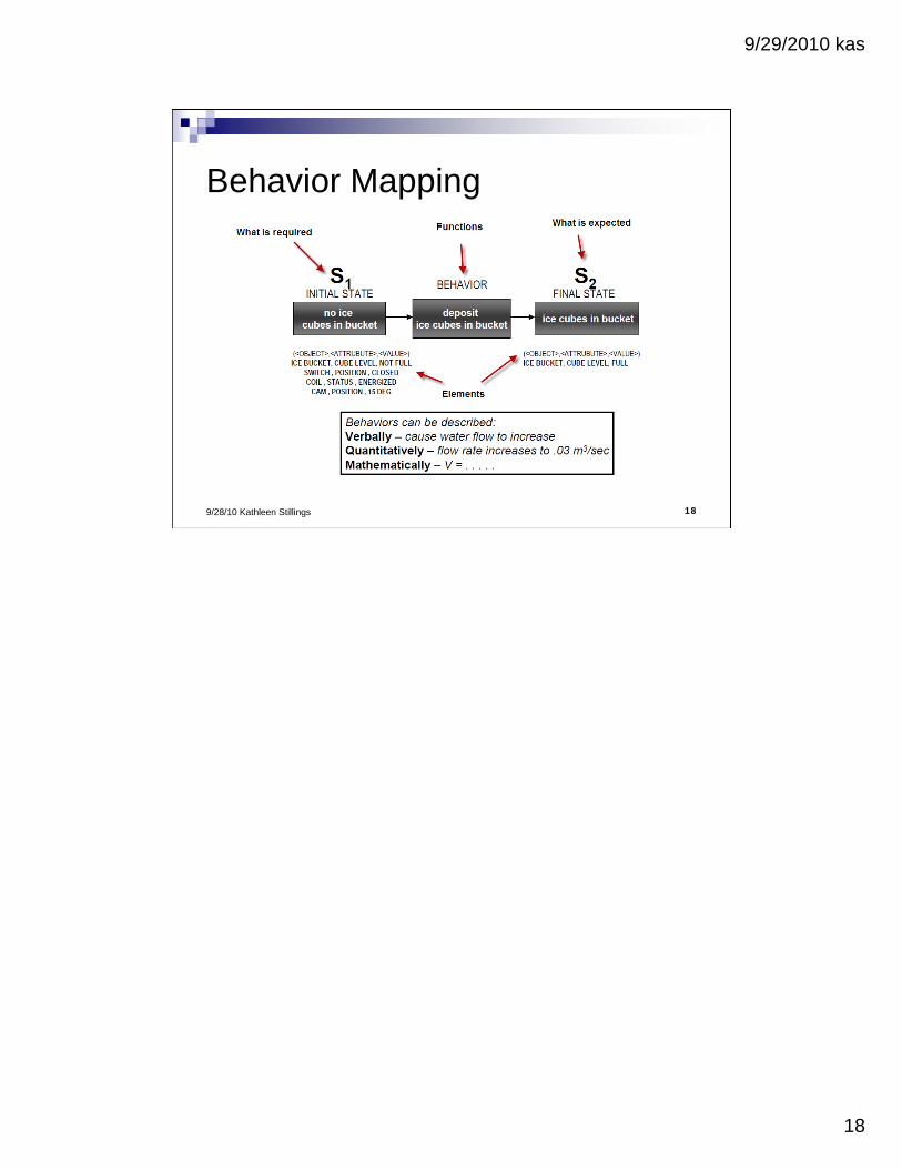
Behavior Modeling
Define the relationships between: Functions: the overall purpose of the process
in verb + noun format
States: “what is required” and “what is expected”
Elements: physical entities that enable functions to achieve “what it expected”
States: pre-conditions (what is required) and post-conditions (what is expected)
9/29/2010 kas
11
119/28/10 Kathleen Stillings
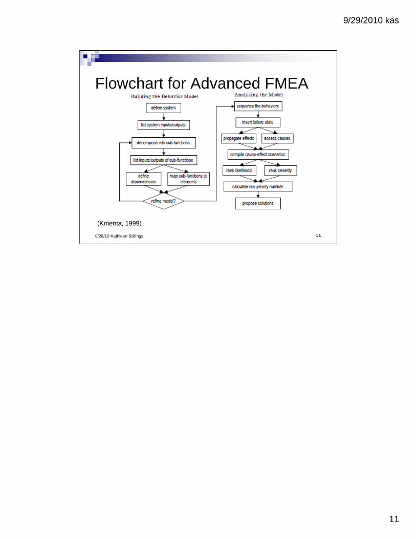
Flowchart for Advanced FMEA
(Kmenta, 1999)
9/29/2010 kas
12
129/28/10 Kathleen Stillings
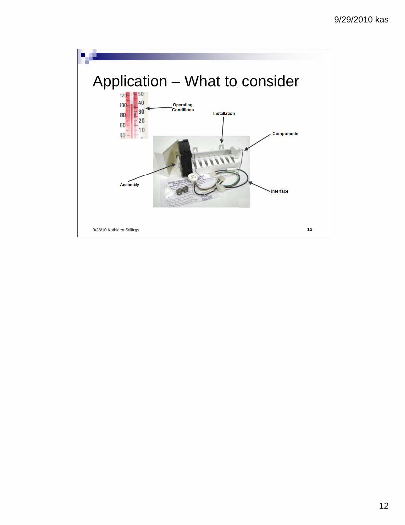
Application – What to consider
9/29/2010 kas
13
139/28/10 Kathleen Stillings
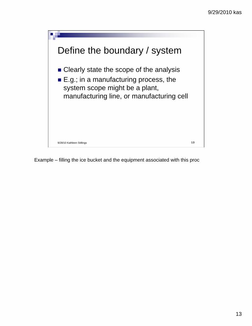
Define the boundary / system
Clearly state the scope of the analysis
E.g.; in a manufacturing process, the system scope might be a plant, manufacturing line, or manufacturing cell
Example – filling the ice bucket and the equipment associated with this proc
9/29/2010 kas
14
149/28/10 Kathleen Stillings
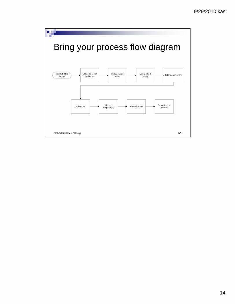
Bring your process flow diagram
Ice Bucket is Empty
Release water valve
Sense no ice in the bucket
Verify tray is empty
Fill tray with water
Sense temperature
Freeze ice Rotate ice trayDeposit ice in
bucket
9/29/2010 kas
15
159/28/10 Kathleen Stillings
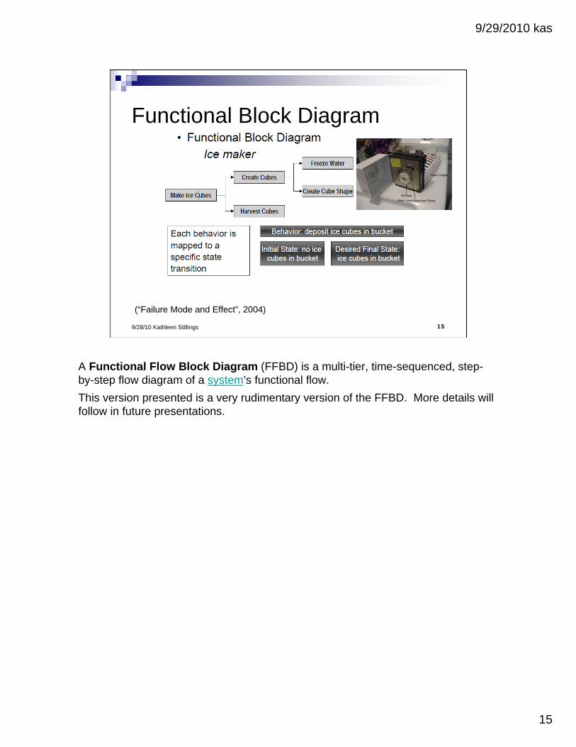
Functional Block Diagram
(“Failure Mode and Effect”, 2004)
A Functional Flow Block Diagram (FFBD) is a multi-tier, time-sequenced, step-by-step flow diagram of a system’s functional flow.
This version presented is a very rudimentary version of the FFBD. More details will follow in future presentations.

9/29/2010 kas
16
169/28/10 Kathleen Stillings
Define the Process Functions
Verb + noun
What functions in your process convert an input into an output?
9/29/2010 kas
17
179/28/10 Kathleen Stillings
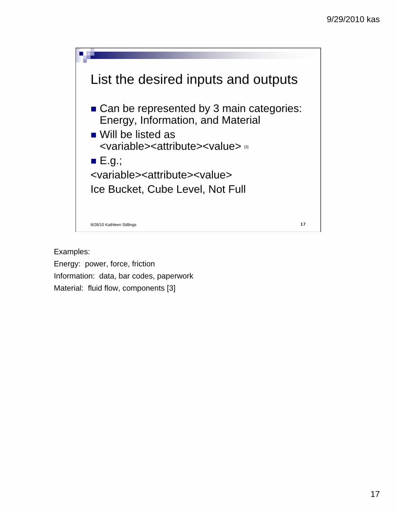
List the desired inputs and outputs
Can be represented by 3 main categories: Energy, Information, and Material
Will be listed as <variable><attribute><value> [3]
E.g.; <variable><attribute><value>Ice Bucket, Cube Level, Not Full
Examples:
Energy: power, force, friction
Information: data, bar codes, paperwork
Material: fluid flow, components [3]
9/29/2010 kas
18
189/28/10 Kathleen Stillings
Behavior Mapping

9/29/2010 kas
19
199/28/10 Kathleen Stillings
Decompose the process
9/29/2010 kas
20
209/28/10 Kathleen Stillings
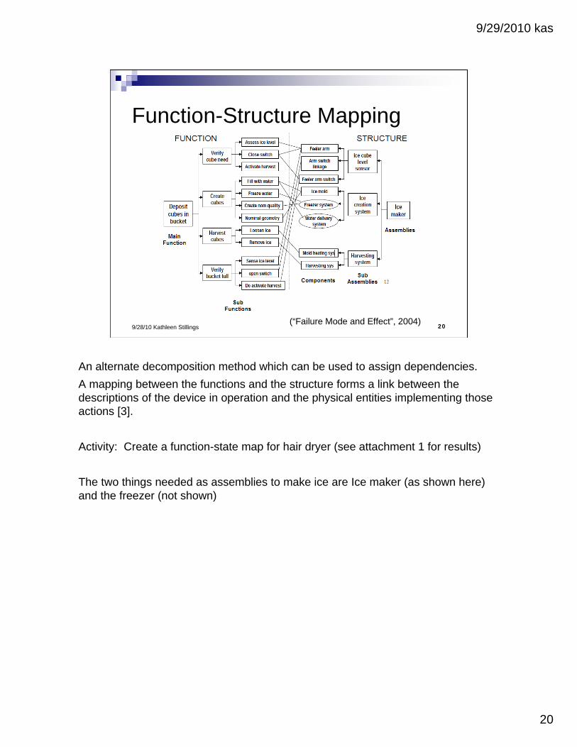
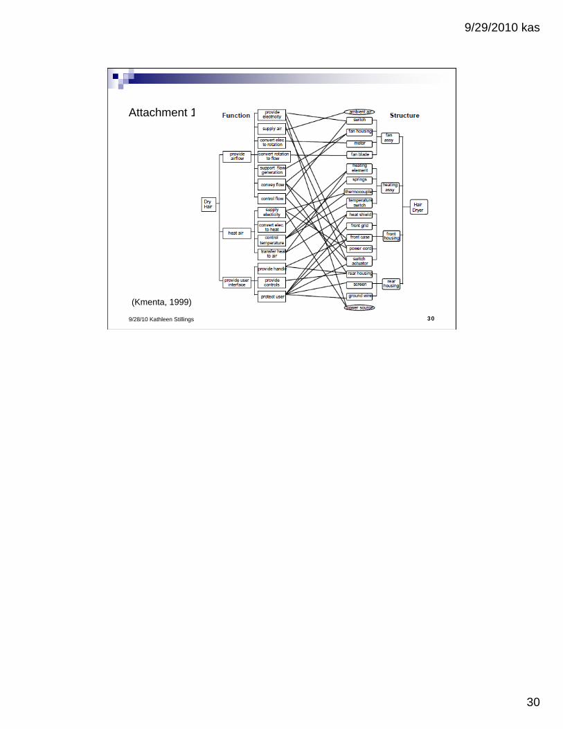
Function-Structure Mapping
(“Failure Mode and Effect”, 2004)
An alternate decomposition method which can be used to assign dependencies.
A mapping between the functions and the structure forms a link between the descriptions of the device in operation and the physical entities implementing those actions [3].
Activity: Create a function-state map for hair dryer (see attachment 1 for results)
The two things needed as assemblies to make ice are Ice maker (as shown here) and the freezer (not shown)

9/29/2010 kas
21
219/28/10 Kathleen Stillings
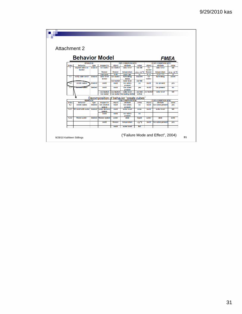
Map the Behavior to the Structure
Exercise: create the behavior model for deposit ice cubes in bucket – see attachment 2
9/29/2010 kas
22
229/28/10 Kathleen Stillings
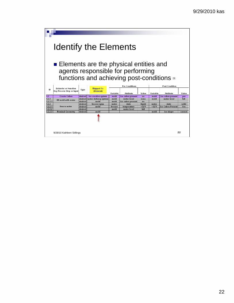
Identify the Elements
Elements are the physical entities and agents responsible for performing functions and achieving post-conditions [3]
9/29/2010 kas
23
239/28/10 Kathleen Stillings
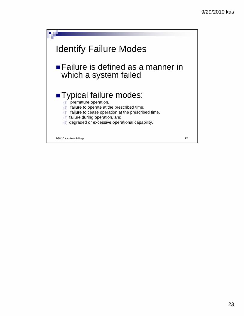
Identify Failure Modes
Failure is defined as a manner in which a system failed
Typical failure modes:(1) premature operation, (2) failure to operate at the prescribed time, (3) failure to cease operation at the prescribed time, (4) failure during operation, and (5) degraded or excessive operational capability.

9/29/2010 kas
24
249/28/10 Kathleen Stillings
Failure Modes ID Process – Step 1
(Deposit cubes in bucket) (Create Cubes)
(Fill with Water)
(Freeze Water)
(Nominal Geometry) Mold
vMold
Water Delivery System
Freezer
9/29/2010 kas
25
259/28/10 Kathleen Stillings
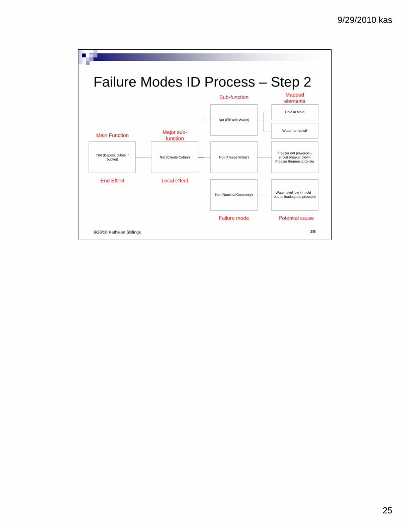
Failure Modes ID Process – Step 2
Not (Deposit cubes in bucket)
Main Function
End Effect
Not (Create Cubes)
Major sub-function
Local effect
Not (Fill with Water)
Sub-function
Failure mode
Not (Freeze Water)
Not (Nominal Geometry)Water level low in mold –
due to inadequate pressure
Mapped elements
Potential cause
Hole in Mold
Freezer not powered –circuit breaker blown
Freezer thermostat broke
Water turned off

9/29/2010 kas
26
269/28/10 Kathleen Stillings
Plug the data into your FMEA template
Handout sample Behavioral - FMEA Matrix
9/29/2010 kas
27
279/28/10 Kathleen Stillings
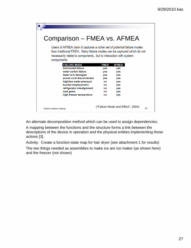
Comparison – FMEA vs. AFMEA
(“Failure Mode and Effect”, 2004)
An alternate decomposition method which can be used to assign dependencies.
A mapping between the functions and the structure forms a link between the descriptions of the device in operation and the physical entities implementing those actions [3].
Activity: Create a function-state map for hair dryer (see attachment 1 for results)
The two things needed as assemblies to make ice are Ice maker (as shown here) and the freezer (not shown)
9/29/2010 kas
28
289/28/10 Kathleen Stillings
Coming Up
FMEA Continued…
How to measure your FMEA effectiveness
Possible Future Presentation:
Functional Flow Diagramming
9/29/2010 kas
29
299/28/10 Kathleen Stillings
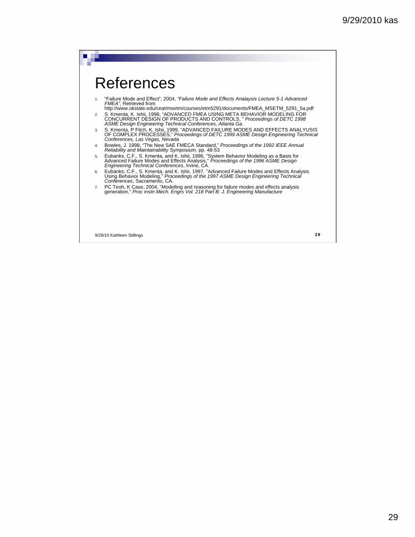
References1. “Failure Mode and Effect”, 2004, “Failure Mode and Effects Analaysis Lecture 5-1 Advanced
FMEA”, Retrieved from http://www.okstate.edu/ceat/msetm/courses/etm5291/documents/FMEA_MSETM_5291_5a.pdf
2. S. Kmenta, K. Ishii, 1998, “ADVANCED FMEA USING META BEHAVIOR MODELING FOR CONCURRENT DESIGN OF PRODUCTS AND CONTROLS, “ Proceedings of DETC 1998 ASME Design Engineering Technical Conferences, Atlanta Ga.
3. S. Kmenta, P Fitch, K. Ishii, 1999, “ADVANCED FAILURE MODES AND EFFECTS ANALYUSIS OF COMPLEX PROCESSES,” Proceedings of DETC 1999 ASME Design Engineering Technical Conferences, Las Vegas, Nevada
4. Bowles, J. 1998, “The New SAE FMECA Standard,” Proceedings of the 1992 IEEE Annual Reliability and Maintainability Symposium, pp. 48-53
5. Eubanks, C.F., S. Kmenta, and K. Ishii, 1996, "System Behavior Modeling as a Basis for Advanced Failure Modes and Effects Analysis," Proceedings of the 1996 ASME Design Engineering Technical Conferences, Irvine, CA.
6. Eubanks, C.F., S. Kmenta, and K. Ishii, 1997, "Advanced Failure Modes and Effects Analysis Using Behavior Modeling," Proceedings of the 1997 ASME Design Engineering Technical Conferences, Sacramento, CA.
7. PC Teoh, K Case, 2004, “Modelling and reasoning for failure modes and effects analysis generation,” Proc instn Mech. Engrs Vol. 218 Part B: J. Engineering Manufacture
9/29/2010 kas
30
309/28/10 Kathleen Stillings
Attachment 1
(Kmenta, 1999)
9/29/2010 kas
31
319/28/10 Kathleen Stillings
Attachment 2
(“Failure Mode and Effect”, 2004)