advanced analysis of pre-tensioned bowstring structures
TRANSCRIPT

Steel Structures 6 (2006) 153-162 www.kssc.or.kr
Advanced Analysis of Pre-tensioned Bowstring Structures
J Y Richard Liew* and Jin-Jun Li
Department of Civil Engineering, National University of Singapore, Blk E1A, #05-13, 1 Engineering Drive 2, Singapore, 117576
Abstract
Bowstring steel structure is a novel cable-tensioned space structure in which out-of-plane stability is ensured by pre-tensionedcables acting as bows. In this paper, an advanced analysis method considering both geometrical and material nonlinearities hasbeen developed to predict the collapse behavior of pre-tensioned steel structures. Special emphasis is placed on the modelingof pre-tensioned cable and the nonlinear beam-column connections. Novel connectors connecting rectangular hollow sectionbeam and column have been proposed and tested to obtain their moment-rotation relationship. Numerical work on three-dimensional bowstring structures shows that their load-displacement behavior is dependent not only on structuralconfigurations, but also on the applied load sequence and the magnitude of pretension forces.
Keywords: Advanced analysis, Bowstring structure, Buckling, Pre-tensioned cable, Semi-rigid beam-column connection
1. Introduction
Pre-tensioning technique has been widely and successfully
used in the construction of long-span suspension or cable-
stayed bridges and high-rise steel towers. The adoption of
such technique in building structures provides aesthetically
pleasing and light-weight solutions. Pre-tensioned steel
structures such as pre-tensioned truss (Kosaka, et al.,
1988), arch (Barnes and Dickson, 2000), dome (Wang,
2004) and grid space structures (Barnes and Dickson,
2000; Bradshaw, et al., 2002) have found many engineering
applications in wide-span or large-space buildings. Dong
and Zhao (2004) presented several recent applications of
pre-tensioned steel space structures in China.
Previous works by Liew et al. (2001) and Chan et al.
(2002) studied the behavior of pre-tensioned steel columns.
Very little work has been done on advanced analysis of
pre-tensioned steel structures. Bowstring column and
space frame are novel cable-tensioned space steel
structures in which out-of-plane stability is ensured by
pre-tensioned cables acting as bows. Bowstring structures
have potential applications as supporting members of
building entrance canopy or glass façade wall to reduce
the need of artificial lighting. However, application of
bowstring structures posts a new challenge requiring
more complex nonlinear solution techniques to capture
the behavior of such structures. This paper presents the
modeling techniques using advanced analysis to study the
nonlinear response of bowstring structures. Effects of
cable profile configurations, cable pretension forces, length
and spacing of horizontal struts on behavior of pre-
tensioned steel columns are examined. For the bowstring
frame structure, structural layout, effects of loading
sequence and pretension forces are investigated. A novel
kind of joint connecting rectangular hollow section beam
and column is proposed and tested to obtain the moment-
rotation relationship.
2. Advanced Analysis of Bowstring Structures
2.1. Inelastic beam-column element
Structural steel frameworks can be efficiently modeled
by 3D beam-column plastic hinge element, as shown in
Fig. 1. The element formulation is based on the updated
Lagrangian approach where all physical quantities in
current configuration are referred to the last calculated
configuration. Transverse displacements of the beam-
column element are calculated using the stability interpolation
functions satisfying the equilibrium equation of beam-
column subject to end forces. The beam-column formulations
can capture accurately the member bowing effect and
initial out-of-straightness by modeling each physical
member using only one beam-column element (Liew, et
al., 2000).
A plasticity model that accounts for partial yielding and
hardening is formulated according to the bounding
surface concept proposed by Hilmy and Abel (1985). The
plasticity model employs two interaction surfaces, one
initial yielding surface and the other full yielding
bounding surface, as shown in Fig. 2. The initial yield
surface bounds the region of elastic cross-sectional
behavior, while the bounding surface defines the state of
full plastification of the cross-section. The initial yield
*Corresponding authorTel: +65-6874-2154, Fax: +65-6779-1635E-mail: [email protected]

154 J Y Richard Liew and Jin-Jun Li
surface is assumed to be a scaled down version of the
bounding surface that is fixed in size and translates
without rotation in stress-resultant space. Although the
plasticity model has several parameters for modeling the
behavior of plastic hinges, the one to the most influence
structural inelastic behavior is possibly the size of initial
yielding surface, i.e., surface extension parameter. Surface
extension parameter is actually to be the reciprocal of the
cross-section’s shape factor. But to catch the effects of
initial imperfection of welded members, smaller values
can be selected to reflect pre-emerging initial yielding in
the cross-section due to residual stresses. A discussion
about effects of the surface extension parameter on load-
carrying capacity of CHS columns was provided in
previous work (Liew and Tang, 2000). Once yielding is
initiated, the yield surface will translate so that the state
of sectional resultants remains on the yield surface during
subsequent plastic loading.
2.2. Semi-rigid connection
Modeling of the moment-rotation relationship is a
fundamental requirement for any consideration of
interaction of connection and member behavior. A large
number of experimental tests have clearly demonstrated
nonlinearities between moment and rotation for almost all
types of connections. The four-parameter power model
has been adopted to model a connection (Goldberg and
Richard, 1963; Abbott and Richard, 1975; Liew, 2001)
(1)
where Ke is initial stiffness of connection, Kp strain-
hardening stiffness of connection, M0 a reference moment,
and n shape parameter (Fig. 3). The evaluating procedure
of four parameters in Eq. (1) for the best representation of
the moment-rotation curves has been provided by Attiogbe
and Morris (1991). By differentiating Eq. (1) with respect
to θ, the tangent stiffness of the connection can be
obtained. To allow for unloading of the connection
associated with non-proportional loading and inelastic
force redistribution, the unloading stiffness is assumed to
be equal to the initial stiffness as shown in Fig. 3.
In general, there are two different ways to incorporate
connection flexibility into computer-based structural
analysis of steel frameworks. The first is to introduce
additional connection elements, or say spring elements,
that model the beam-to-column connections directly. In
the second approach each beam-column member with
semi-rigid connections comprises a finite-length member
with a zero-length virtual “rotation spring” attached at
each end which will be represented in the stiffness matrix
of beam-column elements with fixity or rigidity factors
(Xu, 2002). For three-dimensional frame analysis, it is
convenient to model semi-rigid connections with physical
rotational spring elements, since it allows the relative
torsional and flexural rotations between the member end
and the connection. The first method is adopted in the
present analysis.
2.3. Pre-tensioned cable element
Cable may be modeled by line element which can only
resist tension force (Li and Chan, 2004). The elongation
of the cable element is the unique natural deformation.
By analyzing the relationship of elongation with tension
force and incorporating the coordinate transformation, the
incremental elastic stiffness matrix for the cable element
can be written as
MK
eK
p–( )θ
1 KeK
p–( )θ M
0⁄
n+[ ]
1 n⁄---------------------------------------------------- K
pθ+=
Figure 1. 3D beam-column element.
Figure 2. Two surface plasticity model.
Figure 3. Four-parameter power model for semi-rigidconnections.

Advanced Analysis of Pre-tensioned Bowstring Structures 155
(2)
where E is the material modulus of elasticity, A and l0are respectively the sectional area and the original length
of the cable, and C is the direction cosine vector which
can be expressed as
(3)
where the index i takes on value 1, 2, 3 corresponding
to the respective global axes X1, X2 and X3 in Fig. 4.
The geometric stiffness furnishes the relationship
between the change in the global nodal force components
and the global nodal displacements when the element
natural tension is held invariant. Hence, by examining
these nodal tension components before and after
imposition of the nodal displacement, the geometric
stiffness can be expressed as,
(4)
where T is the cable tension and I3 is a 3×3 unit matrix.
The nonlinear stress-strain relationship of the cable
material is assumed to be defined by Eq. (5) originally
proposed by Jonatowski and Birnstiel (1970)
(5)
where ε is cable strain, f stress, E initial elastic modulus
and fu ultimate stress which is taken as the yield stress, fy,
for an elastic-perfectly plastic material, n a constant
relating to the shape of the stress-strain curve.
During unloading and reloading, the stress-strain
relationship is assumed to be linear, with the slope equal
to the initial elastic modulus E. A cable element is
considered to be slacken when its axial strain becomes
less than its permanent strain (see Fig. 5). The axial force
of a slacken cable is set equal to zero, and its axial
stiffness is considered to be negligible.
The pretension force T0 (only positive in tension) in
the cable can be modeled by imposing a temperature
change ∆t (positive as increase) (Liew et al., 2001),
∆t = −T0/αEA (6)
where α is coefficient of thermal expansion, EA axial
stiffness.
3. Bowstring Column
Bowstring steel column was first investigated by Liew
et al. (2001), where effects of geometric imperfection and
cable pre-tension forces were considered. Chan et al.
(2002) presented a stability analysis and parameter study
of pre-stressed cable-stay columns. In this section, the
nonlinear behavior of pre-tensioned bowstring columns is
examined with advanced analysis. Different structural
configurations, cable pretension forces, and length and
spacing of horizontal struts are examined.
3.1. Main concept
Pre-tensioned steel column generally comprises main
column, horizontal strut and cables, as shown in Fig. 6.
The column is the main component which resists gravity
load, while horizontal struts and pre-tensioned cables
work together as the intermediate lateral support to the
main column. The study in this paper is carried out using
only circular hollow sections for the main column and
horizontal struts, due to the aesthetic reasons and the fact
that circular hollow section offers better resistance to
lateral torsional buckling compared to H or I sections. A
summary of the material properties and section size used
for analysis is shown in Table 1. Pre-tensioned steel
columns with length of 10 m, 15 m and 20m are selected
in that their slenderness ratios LV/r (LV is the spacing of
horizontal struts and r is the radius of gyration), 83, 125
Ke[ ]Cable
EA
l0
-------CC
TCC–
T
CC–TCC
T=
Ci
1
l0
--- XJi XIi–( )=
Kg[ ]Cable
1
l0
---I3CC
T– I
3CC
T–( )–
I3CC
T–( )– I
3CC
T–
=
fEε
1Eε
fu------
n+
1 n⁄---------------------------=
Figure 4. Cable element in global coordinate.
Figure 5. Stress-strain curve of cable material.

156 J Y Richard Liew and Jin-Jun Li
and 166 respectively, are within the general range of
engineering application.
The bottom end of the pre-tensioned steel columns is
assumed to be restrained in three translational directions
and torsion while free to rotate. However, the support at
the top of the column is free to translate in the vertical
direction and rotate but it is restrained in the other two
translational directions and torsion.
Initial geometric imperfection of L/500 magnitude is
introduced to the main column (L is the column length).
The imperfection pattern is assumed to be the same as the
first buckling mode of the main column.
3.2. Structural configurations
There are many types of cable shapes, or restraining
configurations, for the pre-tensioned steel columns, such
as triangular, rectangular and bowstring shapes as shown
in Fig. 6. The bowstring column configuration is defined
by a second-order polynomial equation which describes a
parabolic curve. Configurations defined with other
higher-order polynomial equations will not be included in
present analysis. The numerical examples are designed
for triangular, rectangular and bowstring columns with
three lengths of 10 m, 15 m and 20 m and with 3
horizontal struts uniformly spaced. The maximum length
of horizontal struts at mid-span is assumed as L/16 (L is
the column length) for three configurations. The same
cable forces of 11 kN are pre-tensioned for different
column lengths and different column configurations. All
pre-tensioned columns are subjected to initial geometric
imperfection and axial compression force. The results of
axial load capacities are listed in Table 2 and the
corresponding failure modes are shown in Fig. 7.
Figure 6. Three types of pre-tensioned steel column: (a)triangular; (b) rectangular; (c) bowstring.
Table 1. Summary of the material properties used foranalysis of bowstring columns
Elements Material properties Section size
Vertical strutfy = 275 MPaE = 205 GPa
CHS 88.9×4.0 mm
Horizontal strutfy = 355 MPaE = 205 GPa
CHS 60.3×4.0 mm
Pre-tensioned cablefy = 460 MPaE = 150 GPa
Diameter 10 mm
fy is the design strength and E is the Young’s modulus
Table 2. Axial load capacities of different columnconfigurations with different lengths (Unit: kN)
Length
Configuration10 m 15 m 20 m
Triangular 122 94 59
Rectangular 165 115 69
Bowstring 183 121 74
Figure 7. Failure modes of pre-tensioned steel columns with lengths of 10 m, 15 m and 20 m: (a) triangular; (b) rectangular;(c) bowstring.

Advanced Analysis of Pre-tensioned Bowstring Structures 157
The bowstring column has the highest axial load
capacity as compared to the triangular shape column the
lowest capacity. The rectangular columns can be the
alternative choice if the column has relative large
slenderness ratio (more than 100). For triangular cable
shape, the horizontal struts at quarter-span are not fully
effective to provide lateral restrain forces to the main
column so that bulking occurs earliest. Although
insufficient support also exists at mid-span horizontal
strut due to the equal length for all struts in rectangular
cable shape, this disadvantageous effect will decrease
with the development of lateral deflection at mid-span.
Bowstring cable shape can provide a harmonious lateral
restrain forces to both mid-span and quarter-span
horizontal struts, and give a highest capacity. Since
bowstring column is the most efficient configuration, it
will be used in the subsequent sections to investigate the
effects of cable pre-tension force, length and spacing of
horizontal struts.
3.3. Cable pre-tension force
Cable pre-tension force is an important parameter that
affects the stiffness and strength of the pre-tensioned steel
columns. The effects of cable pre-tensions on the load
capacity of bowstring columns with lengths of 10 m,
15 m and 20 m are investigated. The columns studied
here have 3 horizontal struts uniformly spaced and the
maximum length of horizontal struts at mid-span is
assumed as L/16 (L is the column length). It is assumed
that the yield stress of cable material is 460 Mpa. Since
the diameter of cables is 10 mm, the yielding load of the
cable is about 36 kN. The bowstring columns are
analyzed using advanced analysis by assuming different
pre-tensioning forces in the cables. The results are
presented in Fig. 8 showing the axial capacity of the
column versus the pre-tension force to which is
normalized by the cable yield load, Ty. Cable pre-tensions
equal to 5% of cable yield load can evidently improve the
column capacity when compared to the cases without
cable pre-tensions. The preferred range of cable pre-
tension force is related to the column slenderness and can
be found generally between 30% and 50% of cable yield
strength. When the pre-tension force is too high (more
than 50% of the cable yield strength) the axial capacity of
bowstring columns will reversely decrease, as shown in
Fig. 8. This is because high pre-tensioning force in the
cables will introduce high compression load on the main
column and thus reduce its load-bearing capacity.
3.4. Length of horizontal strut
The length of horizontal struts in bowstring columns is
limited for the sake of aesthetic reasons and restraint
effectiveness. By changing the length of horizontal struts
of bowstring columns, its effects on the column ultimate
capacities can be examined. The numerical results are
listed in Table 3, where the three lengths of horizontal
struts studied are L/8, L/16 and L/24 (L is the column
length). For the 10 m long columns, yielding of
horizontal struts are not observed in numerical analysis
and the longer the horizontal struts, the higher the column
capacity. However, in the case of L/8 for 15 m and 20 m
long columns, yielding of horizontal struts occurs before
column failure and causes the pre-matured collapse of
columns when compared with the case of L/16, as shown
in Table 3. If the section of horizontal struts is
strengthened and replaced by CHS 80.0×4.0, the
capacities are 135 kN and 76 kN respectively for 15 m
and 20 m long bowstring columns with L/8 long
horizontal struts, which are higher than those of L/16
because yielding of horizontal struts are prevented. It can
be drawn from investigation in this section that horizontal
struts should be adequately designed to prevent pre-
matured yielding or buckling and when longer struts are
used more attention should be paid to the possibility of
yielding of the horizontal struts.
Figure 8. Axial load capacity vs. cable pretensions forbowstring columns.
Table 3. Axial load capacities of bowstring columns ofdifferent lengths of horizontal strut and column lengths
(Unit: kN)
Column Length (L)
Horizontal strut length10 m 15 m 20 m
L/8 210 103 63
L/16 183 121 74
L/24 118 104 77
Table 4. Axial load capacities for bowstring columns ofdifferent number of horizontal strut and column lengths
(Unit: kN)
Column Length (L)
Number of horizontal strut10 m 15 m 20 m
3 183 121 74
4 194 154 96
5 196 163 113

158 J Y Richard Liew and Jin-Jun Li
3.5. Spacing of horizontal strut
The spacing of horizontal struts LV is varied as L/4, L/
5 and L/6 for 10 m, 15 m and 20 m long bowstring
columns. The length of horizontal struts is kept to be L/
16 and the cable pre-tensioned to be 11 kN as above. The
axial capacities obtained from advanced analysis are
listed in Table 4. A general conclusion can be drawn that
the more number of horizontal struts are provided, the
higher compressive capacity, especially for the columns
with relatively high slenderness ratio. This is because of
the reduction of the effective buckling length of the main
column between two lateral restrained points. However,
increasing the number of restrained points will not further
increase the capacity because the failure will be caused
by the overall buckling of the bowstring column.
4. Bowstring Frame
The concept of bowstring column can be extended to
3D frames, if the stability of support columns in the out-
of-plane is ensured by bowstring cables while that in-
plane stability is provided by frame action. Based on the
study of bowstring column, structural behavior of
bowstring frame is analyzed in this section, where the
structural layout, novel semi-rigid connection, structural
nonlinearities under environmental loads and effects of
cable pretensions are addressed.
4.1. Structural layout
A bowstring structure supporting a glass facade is
shown in Fig. 9. It consists of seven dependent frames (3
on left and 4 on right) plus one lateral bracing frame. The
detailed model of a bracing frame is shown in Fig. 10,
which includes the elevation view in X-Y and Y-Z planes.
When the bowstring frames are assembled, pre-tension
force is applied to the bowstring cables and bracing
cables to provide lateral stiffness in the in-plane and out-
of-plane direction of the frame. After roof slab and glass
façade are constructed, the bowstrings are under
compression and a second stage pre-tension force is
applied to the cables so that they can have sufficient
lateral stiffness to resist further loadings such as imposed
roof load and wind load. The load sequences of the
bowstring structures are tabulated in Table 5.
4.2. Testing of mullion-to-transom and transom-to-
hanger connection
Mullion-to-transom and transom-to-hanger connections
of frame in-plane are designed as those of semi-rigidity.
Figure 9. The structural model of bracing bowstringframe and a roof slab.
Figure 10. The structural model of bracing bowstring frame: (a) X-Y plane; (b) Y-Z plane.

Advanced Analysis of Pre-tensioned Bowstring Structures 159
The rotational stiffness and moment capacity of these two
connections are tested so that nonlinear analysis models
of bowstring frames can be correctly established and then
the structural behavior can be assessed.
The test setup and specimen instrumentations are
illustrated respectively in Fig. 11. Test specimen 1
represents the hanger (100×100×4 mm RHS) to transom
(150×100×5 mm RHS) connection, which consists of one
M24×60 Grade 8.8 HEX. HD. bolt connecting the 20 mm
plate welded on the inside of the hanger to the 30 mm
Table 5. Loads and loading sequence in analysis
Load sequence Load type Load description
1 1st stage pre-tensiona) Tension inside and outside cables to 52 kN and 50 kN respectively;b) Tension bracing cables to 10 kN
2 Deal load
a) Apply dead loads = 301 kN, at upper column points;b) Apply glass façade loads of 1.75 kN/m on vertical mullions and 1.4 kN/m on transoms;c) Apply self-weight
3 2nd stage pre-tensiona) Tension the inside and outside cables to 78 kN and 82 kN respectively;b) Tension bracing cables to 10 kN
4Lateral bracing force(see Fig. 10b)
a) Apply bracing force at left side = 18.834 kN per node;b) Apply bracing force at right side = 23.082 kN per node
5 Temperature effectTemperature inside glass façade reduces 15oC and that outside increases 25oC simultaneously
6
Wind pressure Apply wind pressure = 2.0 kN/m on mullions and 1.6 kN/m on transoms, up to failure
Wind suction Apply wind suction = 1.4 kN/m on mullions and 1.12 kN/m on transoms, up to failure
Figure 11. The test set-up and specimen instrumentation of semi-rigid connections in bowstring frames: (a) set-up; (b)specimen instrumentation; (c) elevation view of connections; (d) A-A view of specimen 1; (e) A-A view of specimen 2.
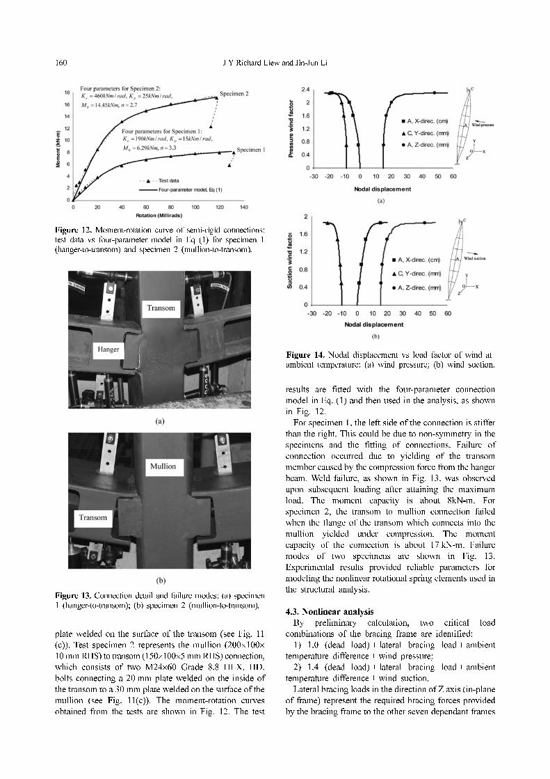
160 J Y Richard Liew and Jin-Jun Li
plate welded on the surface of the transom (see Fig. 11
(c)). Test specimen 2 represents the mullion (200×100×
10 mm RHS) to transom (150×100×5 mm RHS) connection,
which consists of two M24×60 Grade 8.8 HEX. HD.
bolts connecting a 20 mm plate welded on the inside of
the transom to a 30 mm plate welded on the surface of the
mullion (see Fig. 11(c)). The moment-rotation curves
obtained from the tests are shown in Fig. 12. The test
results are fitted with the four-parameter connection
model in Eq. (1) and then used in the analysis, as shown
in Fig. 12.
For specimen 1, the left side of the connection is stiffer
than the right. This could be due to non-symmetry in the
specimens and the fitting of connections. Failure of
connection occurred due to yielding of the transom
member caused by the compression force from the hanger
beam. Weld failure, as shown in Fig. 13, was observed
upon subsequent loading after attaining the maximum
load. The moment capacity is about 8kN-m. For
specimen 2, the transom to mullion connection failed
when the flange of the transom which connects into the
mullion yielded under compression. The moment
capacity of the connection is about 17 kN-m. Failure
modes of two specimens are shown in Fig. 13.
Experimental results provided reliable parameters for
modeling the nonlinear rotational spring elements used in
the structural analysis.
4.3. Nonlinear analysis
By preliminary calculation, two critical load
combinations of the bracing frame are identified:
1) 1.0 (dead load) + lateral bracing load + ambient
temperature difference + wind pressure;
2) 1.4 (dead load) + lateral bracing load + ambient
temperature difference + wind suction.
Lateral bracing loads in the direction of Z axis (in-plane
of frame) represent the required bracing forces provided
by the bracing frame to the other seven dependant frames
Figure 12. Moment-rotation curve of semi-rigid connections:test data vs four-parameter model in Eq (1) for specimen 1(hanger-to-transom) and specimen 2 (mullion-to-transom).
Figure 13. Connection detail and failure modes: (a) specimen1 (hanger-to-transom); (b) specimen 2 (mullion-to-transom).
Figure 14. Nodal displacement vs load factor of wind at ambient temperature: (a) wind pressure; (b) wind suction.

Advanced Analysis of Pre-tensioned Bowstring Structures 161
within one load-bearing unit (see Fig. 10 and Table 5).
According to BS5950-1 (2000), where three or more
intermediate lateral restraints are provided each intermediate
lateral restraint should be capable of resisting a force of
not less than 1% of the compression force.
For sake of simplification, only nonlinear analysis
results of these two load cases are presented in this paper.
The loads and loading sequences used in analysis are
listed in Table 5.
The typical load-displacement curves and cable tension
variations are illustrated in Fig. 14 and Fig. 15. Nonlinear
structural response is observed when wind loads are
applied. The nonlinearity is due to second-order effects
associated with the axial force acting on the deflected
geometry of the structure, the change in cable tension and
nonlinear behavior of semi-rigid connections. No plastic
hinge is observed up to the structural failure, while
buckling of vertical mullions occurs at the ultimate states.
One of reinforcing cables to vertical mullions will slack
soon after wind loads applied, as illustrated in Fig. 15, but
this does not trigger the collapse of the system because
the other reinforcing cable is still in tension and the structure
is capable of resisting more loads. Large deflections, in
both X-direction and Z-direction, are observed when
instability occurs. But the deflection in X-direction is
dominant rather than that in Z-direction, which implies
the bracing cables are providing effective lateral stiffness
in the frame plane to other dependant frames.
4.4. Effects of pretension
As mentioned above, two-stage pre-tensioning technique
is needed in the construction of the bowstring frames
because the weight of roof and glass façade will reduce
the cable pre-tension forces and the frame stiffness
against wind loads will be insufficient if only first-stage
pre-tensioning applied. In this section, the effects of
pretension forces on the capacity and stiffness of the
bowstring frame, represented with five pretension cases,
case (a to e) as shown in Table 6, are studied.
Fig. 16 illustrates the curves of displacement in X-
direction of Node A with pressure wind factor under
different magnitudes of pretension forces. Local
instability has been found from the numerical results for
the states of “Pretension a” and “Pretension b”, which
indicates that both the first and second stage pretensions
are both essentially necessary for bowstring structures.
“Pretension e” does not produce an evidently higher
ultimate capacity against the wind pressure, compared to
“Pretension d” and “Pretension c”. The rationality of
“Pretension d”, namely the designed pretension force, is
proved as well from Fig. 16 where a satisfied structural
stiffness at nominal pressure wind load (factor = 1) is
shown.
5. Conclusion
This paper studies the nonlinear behaviors of bowstring
steel structures with advanced analysis, where modeling
techniques used include those for steel beam-columns,
semi-rigid connections and tensioned cables.
It can be found that for pre-tensioned steel columns, the
bowstring cable shape has relatively higher capacity than
triangular and rectangular shapes. The preferred cable
pre-tensioned forces are ranging from 30% to 50%
Figure 15. Cable tension vs. load factor of wind atambient temperature: (a) wind pressure; (b) wind suction.
Figure 16. Effects of cable Pretensions (see Table 6 forcable pre-tension cases).
Table 6. Five pretension cases for bowstring frame
CaseFirst stage
pretension (kN)Second stage
pretension (kN)
a 0 0
b 50 0
c 50 45
d 50 80
e 50 115

162 J Y Richard Liew and Jin-Jun Li
yielding strength of cables. The maximum length of
horizontal struts at mid-span of bowstring columns can
generally be 1/16 of column length and for longer struts
more attention should be paid to preventing strut from
yielding as larger restrain forces are required. The spacing
of horizontal struts depends more on the column capacity
required and when the column is relatively short L/4
spacing, namely three sets of struts along column length,
is sufficient and recommended.
In addition to bowstring columns, a bowstring frame is
presented and analyzed with advanced analysis. The
structural layout and loading sequence of bowstring frame
are described. A novel kind of connectors connecting
rectangular hollow section beam and column, with one or
two bolts, has been tested to obtain the moment-rotation
relationship. Effects of cable pretension forces are
examined and the two-stage pre-tensioning of cables is
necessary for the bowstring structures simultaneously
subjected to vertical and lateral loads. Although the
higher pretensions cannot produce evident increase of
ultimate capacity, it substantially provides better stiffness
to reduce deflection due to wind load.
References
Abbott, B J and Richard, R M (1975), “Versatile elastic-
plastic stress-strain formula”, Journal of Engineering
Mechanics Division, ASCE, V101(4), pp. 511-515.
Attiogbe, G and Morris, G (1991), “Moment-rotation
functions for steel connections”, Journal of Structural
Engineering, ASCE, V117(6), pp. 1703-1718.
Barnes, M. and Dickson, M. (2000), Wide span roof
structures, Thomas Telford.
Bradshaw, R et al. (2002), “Special structures: past, present
and future”, Journal of Structural Engineering, ASCE,
V128(6), pp. 691-709.
BS5950-1 (2000), Structural use for steelwork in building,
Code of practice for design - rolled and welded sections
Chan, S L, Shu, G P and Lü Z T (2002), “Stability analysis
and parameter study of pre-stressed stayed columns”,
Engineering Structures, V24, pp. 115-124.
Dong, S. L. and Zhao, Y. (2004), “Pre-tensioned long-span
steel space structures in China”, International Journal of
Applied Mechanics and Engineering, V9(1), pp. 25-36.
Goldberg, J E and Richard, R M (1963), “Analysis of non-
linear structures”, Journal of Structural Engineering,
ASCE, V89(8).
Hilmy, S L and Abel, J F (1985), “A strain-hardening
concentrated plasticity model for nonlinear analysis of
steel buildings”, Proceedings of NUMETA’85, pp. 301-
314.
Jonatowski, J J and Birnstiel, C (1970), “Inelastic stiffened
suspension space structures”, Journal of Structural
Division, ASCE, V96(6), pp. 1143-1166.
Kosaka, K et. al. (1988), “Development of pre-stressed steel
truss “super wing””, Kawasaki Steel Giho, V20(4), pp.
315-324.
Li, J J and Chan, S L (2004), “An integrated analysis of
membrane structures with flexible supporting frames”,
Finite Elements in Analysis and Design, V40, pp. 529-
540.
Liew, J Y R and Tang, L K (2000), “Advanced plastic hinge
analysis for the design of tubular space frames”,
Engineering Structures, V22(7), pp. 769-783.
Liew, J Y R, Chen, H, Shanmugam, N E and Chen, W F
(2000), “Improved nonlinear plastic hinge analysis of
space frame structures”, Engineering Structures, V22(10),
pp. 1324-1338.
Liew, J Y R (2001), “State-of-the-art of advanced inelastic
analysis of steel and composite structures”, J. Steel and
Composite Structures, Techno Press, V1(3), pp. 341-354.
Liew, J Y R, Punniyakotty, N. M. and Shanmugam, N. E.
(2001), “Limit-state analysis and design of cable-
tensioned structures”, International Journal of Space
Structures , V16(2), pp. 95-110.
Wang, B B (2004), Free standing tension structures: from
tensegrity to cable-strut system, Spon, New York.
Xu, L (2002), “Design and optimization of semi-rigid
framed structures”, in: Recent advances in optimal
structural design, Chapter 7, Edited by Burns, S. A.,
ASCE.