advance universal multi-fuel thermal store · 2016-10-11 · installation and user guide advance...
TRANSCRIPT

INSTALLATION ANDUSER GUIDE
ADVANCE UNIVERSALMULTI-FUEL THERMAL
STORE
ADVANCE APPLIANCES LTD
PLEASE RETAIN AND ENSURE SERVICE RECORDSARE KEPT UP TO DATE.
ISSUE 61016
Note: All local regulations including those in reference to national standardsmust be complied with when installing the product, including provisionssurrounding electrical safety.
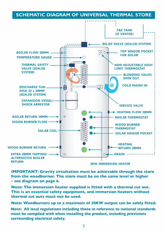
IMPORTANT: Gravity circultation must be achievable through the storefrom the woodburner. The store must be on the same level or higher- see diagram on page 6.Note: The immersion heater supplied is fitted with a thermal cut out.This is an essential safety equipment, and immersion heaters withoutthermal cut outs must not be used.Note: Woodburners up to a maximum of 30KW output can be safely fitted.

OPERATION
INTRODUCTIONThe Advance Universal Thermal Store linking system is a major step forward in thedesign and operation of thermal store systems, allowing for a number of heat inputsto work together for a fully flexible vented or sealed central heating and mainspressure hot water system.
Traditional boilers can be used to heat the thermal store (or heat bank as it issometimes called). Any boilers used in conjunction with this product should beprovided with a boiler thermostat and energy cut out set such that under nocircumstances can the primary flow temperature exceed 100°C. The boiler mustbe capable of a delivering a temperature of 75°C.
If there is any possibility of gravity circulation or pump over-run from the boilerthen consideration should be given to fitting a zone valve and by-pass on the boilerflow circuit wired to close once the store temperature thermostat is satisfied. Thisalso prevents boiler over-run reducing the temperature of the store. (Please seePage 7 for installation recommendation). Boilers can be left live 24hrs as heat lossis minimal. A timer is fitted and pre-wired. The timer can be set to turn the boileron and off, for example to prevent any nuisance overnight firing.
Other appliances can be used by feeding the flow and return into the store. Thesetappings are be used for low input devices such as solid fuel stoves, biomass, cookersand so on. A special pipe set is provided for this purpose. The bottom coil is for asolar thermal input, but can also be used for other suitable inputs. Two 3kwimmersion heaters are fitted, a low position 3kw immersion heater which can assiston extremely low temperature days and a mid position one for hot water boostif needed. These can be coupled to solar PV.
Central heating is drawn from side tappings.
Insulation on this store is excellent, 60mm thick, foam injected with a smart outercase.
The store is capable of working up to 3 bar pressure, making it suitable for allheating circuits, including underfloor, either sealed or open systems.
Hot water is supplied through an efficient internal heat exchanger at mains pressurefor fast, safe hot water delivery and is controlled by a pre-plumbed fitted manifoldwith blending valve and shock arrestor fitted for easy installation.
Note: Units operate at 75°C and heat pumps cannot be the prime heating source.
3
Solar and Ancillary inputsWe can only offer general advice regarding external appliances and fittings. The firstrule is to follow manufacturer’s instructions. Use the solar sensor pockets tocontrol the inputs on the store, and use the spare top pocket as overheatprotection for solar thermal installations.
In summer - the solar season can run from April to September - wood burners,boilers and other inputs other than solar should not be necessary, as solar inputshould exceed the likely hot water requirements during this season. You can setthe solar control to 80°C in the tank, giving ample hot water for domestic needs.An extra pocket is fitted into the store for solar over heat protection.
In installations where the thermal store is sited above the solar collector panelsand if gravity circulation is possible through the solar pump an additional zone valvemay be required.
Unless connected to photovoltaic solar systems the immersion heaters should notbe required during the solar season, although the top one can be wired to aswitched spur for any essential top up.
The immersion heaters should be set at 75°C.
Note: The immersion heater supplied is fitted with a thermal cut out. This isan essential safety requirement, and immersion heaters without thermal cutouts must not be used.
As it is a thermal store, thermal disinfection is not needed.
Some degree of experimentation in operation is likely as different systems will havedifferent loads placed upon them.
Solid fuel systems are ideal – biomass, wood burning stoves or cookers can all beconnected. It is possible to meet sealed system G3 requirements of BuildingRegulations by using the fully assembled SFUTS where the wiring and plumbing isprovided.
Ancillary input is generally of an intermittent nature – for example a wood burneris usually only lit during certain periods of the day and should not be used at all inwarmer weather where solar may be more appropriate. It is recommended that agas/oil boiler is used with any intermittent heat source. Whilst it is possible to useelectricity it can be expensive and off peak tariffs are preferred. Solar PV can beused.
Heat pumps are an option but it must be understood that the store operates at75°C. It is essential that a heat source such as a gas or oil boiler is used for top upand that they achieve at least 75°C output. Each input has a dedicated thermostatso 75°C is easy to achieve with a wood burner for example and will result insubstantial savings on gas or oil bills.
4

VENTED OR SEALED SYSTEMS
SFUTS FULLY WIRED AND PLUMBED FOR SOLID FUELWITH GAS/OIL BOILER ETC
The Universal can be vented or sealed.
A vented version will not have the thermal safety valve, pressure relief valve or tun-dish. It must be vented at the top of the tank and fed at a neutral point in the system.
The standard unit is for use with sealed heating systems. We recommend fittingthis unit as it eliminates the need for a remote feed and expansion tank, suitsunderfloor systems and is easier to fit. There are appropriate levels of control andsafety approved to meet part G of the building regulations fitted to the store, evenwith solid fuel inputs.
For over-temperature control a high limit thermostat turns on the heating pumpwhich acts as a large heat dump. If the temperature in the store still continues torise a non electrical thermal safety valves opens to allow cold water through thehot water coil to cool the store.
For over pressure, a relief valve is fitted to the top of the tank. The pressure reliefand thermal safety valves are pre plumbed into a 28mm tun-dish for safe discharge.
We suggest an extra 3 bar relief valve is fitted in open circuit for additional safetyand a filling loop with appropriate isolation.
The unit should be filled to 1 bar pressure cold. It has a maximum working pressureof 3 bar.
Remember when calculating heating expansion vessel size to include the capacityof all the pipe work, thermal store and heat emitters.
The SFUTS (Solid Fuel Universal Thermal Store) takes the worry out of installation.It offers a fully integrated store with all relevant controls and safety features. It hasthree pumps fitted - a boiler pump, a heating pump and a re-circulator for the solidfuel device to aid heat up and stratification when the appliance is first lit. The sensorhead can be adjusted, we recommend 50°C to 60°C. The sensing probe must beleft as supplied, strapped to the pipework.
A heat sink (towel radiator or similar) needs to fitted as shown in the schematic,it should be sized to accommodate 20% of the woodburner output. Two dualthermostats with over-heat protection are fitted (the third is for solar and is leftto the installer) and a thermal safety valve is fitted in sealed heating circuits, plumbedin with the pressure relief valve to tun-dish discharge. This valve is thermo-mechanical and will work in the case of an interruption to electrical supply.
5

A 3amp supply from a fused spur is recommended, and you will need to wire aprogrammer/ room thermostat to the fitted junction box. Means for disconnectionof the supply must be incorporated in the fixed wiring in accordance with the wiringrules. The mains supply wiring must be fixed in a way that prevents it coming intocontact with hot parts (those that can experience a temperature rise of >50°C), or,that the insulation of the mains supply wiring must be protected, for example, byinsulating sleeving having an appropriate temperature rating.
A flue thermostat is supplied loose (but electrically connected) to mount on the flue.This thermostat senses when the appliance is lit/turned on. Some experimentationmay be required when setting the flue thermostat temperature. We recommend 70°Cto 100°C . It should be mounted using the supplied steel fixing band about 1 metrefrom the stove. It is wired so that it will turn the solid fuel pump on (in conjunctionwith the cylinder thermostat) and turn off the boiler when the stove is lit.
Wiring instructions come with the unit. The wiring centre is labelled for 3amp (50HZ)mains input, switched live boiler and programmer connections.
If the supply cord or any wiring on the store is damaged, it must be replaced by themanufacturer, its service agent or similarly qualified persons in order to avoid ahazard.
You will need to connect the boiler flow and return pipes, the solid fuel flow andreturn and the heating flow and return. Pumps are fitted and pre wired. The solid fuelcircuit contains an injector tee, pump and blending valve to prevent cold water beingreturned to the wood burner.
The unit meets the requirements of G3.
SFUTS SCHEMATIC
This
Flue Stat
schematic is for solid fuel pumped circulation.Note: A heat sink must be fitted
6

Note: If the pipe rises above the thermal store, the wood burner must have aquench pipe system to protect against overheating
SCHEMATIC WITH LOOP
TIMERS FOR BOILER AND SOLID FUELIn order to offer more control Advance are now fitting two timers to the store.
Boiler TimerThe boiler should be timed to be on for at least twelve hours to maintain the storetemperature. However, it can be a nuisance if it comes on overnight. For yourconvenience we now fit a pre-wired timer you can set to time the boiler.
Solid Fuel TimerIf the woodburner, for example, is left burning after you go to bed, it will eventuallycool but may still activate the pump on the woodburner circuit. To alleviate this wesuggest that you set this to off from around midnight and back on in the morning.If the woodburner isn’t lit nothing will happen if the timer is on because othercontrols like the flue thermostat are in the same circuit.
If you light the fire in the morning you will need to be sure that the timer is on.The flue stat is wired so that when the fire is lit the boiler will not come on.
NoteYou don’t have to use these timers - the thermal store works well without them,However they may well aid the efficiency of the operation and prevent nuisanceovernight boiler firing and overnight store cooling.
7

INSTALLATIONEnsure the unit is installed on a flat surface and that all tappings are accessible forfuture maintenance. Make sure the floor will support the full weight of the unit.Ensure that there is sufficient safety clearances and air flow around the unit toprotect the building fabric, paying special regard to any potential hazard that maycause structural damage to the dwelling.Please also ensure that the relevant clearances are present for the installation,servicing and/or removal of any valves, thermostats, immersion heaters or furtherequipment around the thermal storage unit.The system must be inhibited with a suitable proprietary brand taking account ofthe store volume. If vented the feed and expansion tank must be at the highestpoint in the system. A metal feed and expansion tank is preferred.An expansion vessel of suitable capacity must be installed in sealed systems takinginto account the total volume of the heating circuit and thermal store. On page 10we list the expansion required for the cylinder only.Install a propriety filling loop system with flexible hose, isolation valve, 3 bar reliefvalve, expansion vessel and pressure gauge. Fill to 1 bar cold. The filling loop shouldbe installed to prevent back-siphonage.The relief valve and discharge arrangement is fitted with the thermal safety valve insealed heating systems. This is a mechanical device (non-electrical) which opens at97°C and draws cold water through the hot water coil to dissipate heat in thestore. It runs via a tun dish which should be connected via a 28mm pipe to a safelow level discharge point, follow G3 advice here. The pressure-relief device is tobe operated regularly to remove lime deposits and to verify that it is not blocked.A 28mm discharge pipe connected to the tun dish is to be installed in a continuouslydownward direction and in a frost-free environment.The thermal safety valve gives the third level of protection necessary to meet G3.An expansion (pressure relief) valve must be fitted into the heating circuit inaddition to the relief valve on the tank.For solid fuel appliances refer to manufacturer’s instructions, especially with regardto heat sinks and so on. Always install a heat sink that will work on gravity betweenthe store and the solid fuel appliance. Contact the stove manufacturers to ensureits suitability for use with a vented or unvented thermal store system.The SFUTS is pre-wired and pre-plumbed and is simple to install. Follow the layouts carefully, the pumped solid fuel pipe-set is assembled and suppliedpacked with SFUTS. It should be attached to the store. If this is not possible itshould be less than one metre from the store. Full fitting instructions are suppliedwith this pipe set.Ensure all parts are fitted in accordance with the instructions. On completition ofthe installation, check all seals for soundness and check that the vessel is functioningcorrectly. On completion of the installation and commissioning ensure that theoperating instructions for the store are left with the customer. Ensure to advisethe customer on the correct use of the vessel and setting of controls.
8

Pipe outside diameter Maximum heat loss in W/m
Gravity flow is important in case of power cuts etc. Gravity flow is normallyachieved by putting the thermal store on the same level or higher than thewoodburner. If this can’t be achieved a wood burner with a quench pipe must beinstalled in case of overheat.
Set the boiler thermostat to 75°C. Set the solid fuel thermostat to 80°C. This willhelp increase the energy stored in the unit and reduce reliance on fossil fuel. Solarthermal can also operate at 80°C. Boilers must have over-temperature protectionand must be able to supply temperatures of at least 75°C. A zone value and by-pass may be necessary for boilers with pump over run if the store temperature isreduced by more than 3°C.
If your boiler has a pump fitted you can remove the boiler pump on the store anddisconnect the wiring. It will not affect the operation of the system.
In high risk installations (care homes, nurseries etc.) care should be taken to reducecentral heating temperatures with a blending valve. Underfloor heating should berouted through a control manifold. Nuisance gravity circulation should be minimisedusing either zone valves or anti-gravity valves.
In order to comply with Part L Building Regulations it is necessary to insulate anyhot water (primary and secondary) pipework within one metre of the cylinder.Guidance is given in the Table 5 (Page 20) of the 2013 Domestic HeatingCompliance guide. Insulation values for the most popular pipe sizes are reproducedbelow.
NOTE: ALL JOINTS MUST BE TESTED AS THEY CAN LOOSEN IN TRANSIT
15222835
7.899.1210.0711.08
HOT WATERIf hardness exceeds 200ppm, use a treatment to soften water.Scale build-up can happen rapidly and reduce flow and efficiency.Always flush after commissioning but DO NOT USE heavily chlorinated solutionsunless you are prepared to thoroughly flush the whole heating system after heat upand cool down.If flow is poor check incoming water supply and make sure all valves etc. are fullyopen.If temperature is poor check that the store has reached 75°C and that the temperingvalve is set at the appropriate temperature.Use inhibitor in heating systems. Remember to include the store volume when dosing.
9
SERVICINGThis should be done every year. Fill in the form at the back of this publication - youmay need it in case of warranty issues.Service the shock arrestor by inflating to 3 bar and ensure the store is inhibited witha proprietary brand of inhibitor to the recommended dose.Check that the tempering valve is controlling hot water temperature at (about) 55°C.To drain the unit isolate all appliances and drain via the fitted drain cock. On sealedsystems open the relief valve to allow air into the cylinder to prevent collapse.Please see page 14 for full servicing requirements.
WARRANTYWarranty is for ten years on the tank against failure due to manufacturing fault, and twoyears on components supplied and fitted to the heating manifold and thermal store.Conditions apply, the unit must be serviced annually and a record of service must bemaintained. It must be in a frost free environment and must be used for public mainspotable water only. It must be installed and used correctly in accordance withmanufacturer’s requirements and current best practice. Corrosion and scale are notcovered. Chlorine/chloride levels must be below 200ppm. The store must be inhibitedto correct dose.Scale is not covered. Your statutory rights are not affected by the above.Upon any malfunction of the unit ensure that the system is switched off and contactthe manufacturer, its service agent or a similarly qualified person in in order to avoidhazard.
COLD SUPPLY
SIZE & WEIGHT
A minimum of 2 bar (200 MPa) pressure through a 22mm pipe is optimum. Belowthis the performance may be compromised. Test the household supply by turning onmains fed taps to ensure satisfactory flow rates can be achieved.Above 18 litres per minute is the recommended flow. It is the installer’s andhouseholder’s responsibility to check these before installation. Excessive flow ratesmay result in lower hot water temperatures.Fit a 3 bar (300MPa) control valve (not supplied) if pressures are likely to be in excessof this. This is the maximum recommended coil pressure.NOTE: Mains pressures usually increase from late evening to early morning.
* Please add the central heating pipework, radiators/underfloor and appliance volumes to arrive at expansion vessel size.
EXPANSION VESSELMODEL CAPACITY WEIGHT FULL Kg SIZE (CYLINDER ONLY)* HGT X DIA mm
SFUTS 210 210 ltrs 280 18 ltrs 1500 x 600
SFUTS 250 250 ltrs 325 24 ltrs 1750 x 600
SFUTS 300 300 ltrs 380 24 ltrs 2025 x 600
10

DISPOSALAt the end of the life of the product please dispose of in line with any regulationsruling at the time
TECHNICAL SPECIFICATION
SPARE PARTS
MAX COLD WATER PRESSURE 3 BAR
MAX TANK OPERATING PRESSURE 3 BAR
MIN OPERATING TEMPERATURE 75°C
IMMERSION HEATERS 3KW / 230V AC 13/4" x 14"
SHOCK ARRESTOR POTABLE 2 LITRE 3 BAR
HEAT EXCHANGER HOT WATER 35KW
HEAT EXCHANGER SOLAR 17KW
HEAT LOSS 210 LITRE CLASS C 1.67 / 24 HRS 68 WATTSSOLAR VOLUME
80
85
90
HEAT LOSS 250 LITRE CLASS C 1.77 / 24 HRS 74 WATTS
HEAT LOSS 300 LITRE CLASS C 1.93 / 24 HRS 83 WATTS
FOAM GWP / ODP 1 / 0
2 LITRE EXPANSION VESSEL (SHOCK ARRESTOR) AA0001
BLENDING VALVE AA0002B
3KW IMMERSION HEATER 1.75” HIGH TEMP AA0005
SINGLE CONTROL THERMOSTAT AA0010
NON ADJUSTABLE HI LIMIT THERMOSTAT AA0030
DUAL CONTROL THERMOSTAT AA0013
THERMAL SAFETY VALVE AA0016
WIRING CENTRE AA0027
FLUE THERMOSTAT AA0035
28mm INJECTOR TEE AA0029
A RATED PUMP AA0031
3 BAR RELIEF VALVE AA0015
11
SOLAR COIL OUTPUT 20KW (0.75m2)
HOT WATER COIL OUTPUT 35KW (1.5m2)
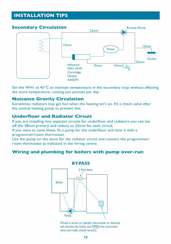
INSTALLATION TIPS
12
Set the WH1 at 45°C to maintain temperature in the secondary loop without affectingthe store temperature, costing just pennies per day.
Secondary Circulation
Sometimes radiators may get hot when the heating isn’t on. Fit a check valve after the central heating pump to prevent this.
Nuisance Gravity Circulation
If you are installing two separate circuits for underfloor and radiators you can tee off the 28mm primary and reduce to 22mm for each circuit.If you want to zone these, fit a pump for the underfloor and time it with aprogrammer/room thermostat.Use the pump on the store for the radiator circuit and connect the programmer/room thermostat as indicated in the wiring centre.
Underfloor and Radiator Circuit
Wiring and plumbing for boilers with pump over-run
22mm
15mm
15mm 15mm
15mm
22mm
Bronze Pump
Outlet
AdvanceWH 1KWCartridgeHeaterAA0291
Timer
BY-PASS2 Port Valve
Pump
Wired in series so cylinder thermostat on demandwill activate the boiler and OPEN the motorisedvalve (normally closed version)
Boiler

CE CERTIFICATE
13

INSTALLER & COMMISSIONING ENGINEER DETAILSCustomer Details
Commissioning Engineer Details
Appliance Details
General Installation
Servicing RequirementsName 1. Check pressure reducing valve
(if fitted) is 3.0 bar static and adjustif necessary.
2. Check flow rates are correct at 18 litresper minute. Clean filter in pressurereducing valve only if required.
4. Check
3. Check inhibitor levels in system.
expansion vessel change is.3.0 bar - inflate as required afterdecommissioning the cold supply.
5. Check blending valve temperatureis 55°C or lower. See manufacturer’sinstallation instructions for any furtherrequirements.
Should further assistance or clarificationbe required contact Advance Advice on01543 377723.
Failure to carry out annual service/maintenance requirements and log proofin service/maintenance records mayinvalidate warranty.
.............................................................................
Address .......................................................................
Tel No. ..........................................................................
...............................................................................................
Name .............................................................................
Address .......................................................................
Tel No. ..........................................................................
DATE ..............................................................................
REGISTRATION DETAILS(where applicable for unvented systems)
REG No. ......................................................................
ID SERIAL No. etc. ..........................................
...............................................................................................
Name .............................................................................
Model ...........................................................................
Capacity Litres......................................................
Serial No.
Has a check been done for jointtightness and leaks? Yes No
...................................................................
Address .......................................................................
Tel No. ..........................................................................
DATE ..............................................................................
REGISTRATION DETAILS(where applicable for unvented systems)
REG No. ......................................................................
ID SERIAL No. etc. ..........................................
...............................................................................................
Has a check been done for electrical safety? Yes No
Installer Details
14

15
SERVICE INTERVAL RECORD
SERVICE 1 Date
Engineers Name...............................................................
Company Name...............................................................
Tel No..................................................................................ID Serial No......................................................................Comments .........................................................................
Signature ............................................................................
................................................................................................
SERVICE 2 Date
Engineers Name...............................................................
Company Name...............................................................
Tel No..................................................................................ID Serial No......................................................................Comments .........................................................................
Signature ............................................................................
................................................................................................
SERVICE 3 Date
Engineers Name...............................................................
Company Name...............................................................
Tel No..................................................................................ID Serial No......................................................................Comments .........................................................................
Signature ............................................................................
................................................................................................
SERVICE 4 Date
Engineers Name...............................................................
Company Name...............................................................
Tel No..................................................................................ID Serial No......................................................................Comments .........................................................................
Signature ............................................................................
................................................................................................
SERVICE 5 Date
Engineers Name...............................................................
Company Name...............................................................
Tel No..................................................................................ID Serial No......................................................................Comments .........................................................................
Signature ............................................................................
................................................................................................
SERVICE 6 Date
Engineers Name...............................................................
Company Name...............................................................
Tel No..................................................................................ID Serial No......................................................................Comments .........................................................................
Signature ............................................................................
................................................................................................
SERVICE 7 Date
Engineers Name...............................................................
Company Name...............................................................
Tel No..................................................................................ID Serial No......................................................................Comments .........................................................................
Signature ............................................................................
................................................................................................
SERVICE 8 Date
Engineers Name...............................................................
Company Name...............................................................
Tel No..................................................................................ID Serial No......................................................................Comments .........................................................................
Signature ............................................................................
................................................................................................
Service regularly by an approved engineer and record details below

advance appl ancesUNIT 4 COPPICE SIDE IND EST BROWNHILLS WALSALL WS8 7EX TEL 01543 377723
16
HOT WATER ASSOCIATION CHARTER MEMBER
Hot Water Association (HWA) Members undertaketo offer their customers the following:
www.hwacharter.org
• To supply Þt for purpose products clearly and honestly described
• To supply products that meet or exceed appropriate standards and building and water regulations
• To provide pre and post sales technical support
• To provide clear and concise warranty details to customers
UNIT 4 COPPICE SIDE IND EST BROWNHILLS For Terms and Conditions go to www.advanceappliances.co.uk
WALSALL WS8 7EX TEL 01543 377723