advance detection - d1upf2v1quehpe.cloudfront.net · advance detection last updated october, 2010...
TRANSCRIPT

1 of 13WX-501-0001 • 02.18
Basic Traffic Signal Timing and Advance Detection
Last updated October, 2010
This document provides a basic introduction to the use of Continuous Tracking Advance Detectors (CTADs) for advance detection at signalized intersections. This alternative type of detector has been used on hundreds of high-speed approaches to extend active through-movement phases to serve queue traffic; promote platoon progression; identify gaps in traffic; and provide safe phase termination.
SmartSensor Advance is the first long-range CTAD adeptly suited for through-movements because it can use multiple criteria (e.g. range, speed, stop-bar ETA, headway and qualified count) to determine if phase extension is desirable. To serve slower-moving traffic flow, time headway in advance of or near the stop bar can be estimated in a fashion similar to traditional presence monitoring with point detectors. For safe and efficient phase termination of high-speed traffic, ETA headway can be monitored in an improved way that dynamically adapts with the actual distribution of speeds on the roadway. Furthermore, speed measurements are used to quickly inhibit the queue output when traffic reaches free-flow in order to help create gap out opportunities and prevent high-speed max out.
In one short-term study (Study C – Impacts of Advance Loop Detection and the SmartSensor Advance on Driver Behavior at High-speed Signalized Intersection, David S. Hurwitz, ITE 2008), a single CTAD was reported to have approximately the same safety benefit (in terms of red-light running) as other innovative advance detection systems that have been evaluated over a longer term.
Study A Study B Study CRight-angle Collisions 31% 50% N/ARear-end Collisions 75%Red-light Running 65% 79% 72%
TABle 1. ReDUCTION OF INCIDeNTS BY NON-TRADITIONAl ADVANCe DeTeCTION
For more information on Study A and Study B, as well as the overall costs and benefits of advance detection systems on high-speed signalized intersections, please refer to the Wavetronix brochure entitled “SmartSensor Advance – SafeArrival Technology.”
This application note offers guidance on CTAD configuration and controller timing necessary for basic integration at isolated intersections. On mainline high-speed through movements, CTAD advance detection has been determined to be the most cost-effective system.
0001

2 of 13WX-501-0001 • 02.18
Phase
Controller
Backplate
Rack Card
Surge Cabinet
CTAD
Queue Detector Channel: < 35 mphAdvance Detector Channel: >35 mph
21
12
Inputs
B: Trailing vehicle A: Leading vehicle
AB Passage Time
MAH = 3.5 s
AB
1.5 s2.5 s5.0 sETAMAH = 3.5 s
PT
AB Safe Gap
165 ft330 ft
Decision dilemma zone
2.5 s5.0 s 0.0 s
A: Last-to-GoB: First-to-stop
200 ft405 ft
(@45 mph)
(@55 mph)
FIgURe 1. ADVANCeD DeTeCTION SYSTeM OVeRVIeW
Not only do CTADs have operation benefits compared to traditional embedded designs, but they offer the clear advantage of being easier to install and maintain. Embedded designs require that each distributed element continue to operate flawlessly, otherwise the phase will gap out prematurely. The FHWA publication Signal Timing on a Shoestring (FHWA-HOP-07-006) comments on this prevalent problem:
“One of the most common signal timing complaints is that the phase time is too short. This is frequently a result of a detector malfunction. The initial response, then, is to confirm that the hardware is operational and the timing parameters are operating as planned.”
With embedded designs, detectors are logically grouped together, making it expensive to replace a malfunctioning detector. It can also be challenging to confirm which detector is the culprit.
The SafeArrival Technology brochure, the SmartSensor Advance User Guide, this application note, and the traffic controller manual documentation can all be used for reference so that your Wavetronix-certified representative can help you convert the concepts outlined for basic timing applications to more advanced scenarios, including volume-density, dynamic maximum green and actuated-coordinated operations.
Traffic Signal TimingThe list below shows some key terms and concepts that will be helpful to know before reading this application note:
˿ Actuated ˿ Extend ˿ Max out ˿ Queue detector ˿ Advance detector ˿ Flow rate ˿ Maximum green ˿ Red change interval ˿ Call ˿ Fully actuated control ˿ Minimum green ˿ Red time ˿ Capacity ˿ Gap ˿ Minimum recall ˿ Saturation flow rate ˿ Change interval ˿ Gap out ˿ Movement ˿ Saturation headway ˿ Clearance lost time ˿ Gap reduction ˿ Passage time ˿ Semi-actuated control ˿ Concurrent phases ˿ Headway ˿ Permissive movements ˿ Simultaneous gap ˿ Cycle ˿ Interval ˿ Phase ˿ Stop bar detector ˿ Cycle length ˿ Isolated intersection ˿ Phasing diagram ˿ Through-movement ˿ Dilemma zone ˿ Lost time ˿ Platoon ˿ Traffic signal controller ˿ Effective green time ˿ Max allowable headway ˿ Presence mode ˿ Yellow change interval
The FHWA website www.signaltiming.com provides traffic professionals with a concise Traffic Signal Timing Manual (FHWA-HOP-08-024) that reviews the objectives of signalized intersection traffic design in the context of long-practiced policies and standardized technologies. This application note presents the material assuming an understanding of the traffic signal design concepts, basic signal timing procedures, and controller parameters as explained throughout the

3 of 13WX-501-0001 • 02.18
Traffic Signal Timing Manual (TSTM) manual (especially sections 3.3–6.3). Please refer to the TSTM for explanations and definitions of the key traffic signal engineering terms and concepts such as those listed above.
While the FHWA does not endorse specific products or manufacturers, it does encourage proactive management of signalized intersection traffic control in order to increase the safety and efficiency of operations. The TSTM stresses that a proactive review of the interaction between signal timing and detection decisions is important to achieve optimal performance. It states:
“The quality of intersection operation is particularly dependent on the relationship between the detection layout and the signal controller settings. For optimum performance, the detector layout and signal settings should be ‘tuned’ to the geometry of the intersection, its traffic volume, and the approach speed. The tuning process consists of finding a balance between detector location (relative to the stop line), detector length, passage time, and minimum green time for the prevailing conditions. However, there is no strong consensus in the industry with regard to what is the ‘best balance.’”
Furthermore, the purposes of signalized intersection detection specifically are stated in the TSTM as follows:
“The objective of detection is to detect vehicle presence and identify gaps in vehicle presence that are sufficiently long to warrant terminating the phase. There are many objectives of detection design that can be characterized with the following statements:
˿ Identify vehicle presence on a phase.
˿ Extend the phase to serve queued traffic and that which is progressed from upstream traffic signals.
˿ Identify gaps in traffic where the phase may be ended and extend the green.
˿ Provide a safe phase termination for high-speed movements by minimizing the chance of a driver being in the in deci-sion zone [also known as a dilemma zone] at the onset of the yellow indication.”
The TSTM uses the inductive loop detector as the example in all of its applications and refers the reader to the Traffic Detector Handbook, 3rd edition (2006) to understand the strengths and weaknesses of alternative traffic sensing technologies. In particular the TSTM acknowledges one weakness of embedded detectors when it states:
“A designer may select a[n] inductive loop detector placement location based on a design manual or agency policy for the design travel speed. What the designer may not realize is once the loop detection is embedded in the pavement, it is difficult to relocate. If the operator or traffic engineer wants to change the posted speed . . . alternate loop locations may be necessary. This would force the costly relocation of the designed loops.”
The purpose of this application note is to explain how proactive use of a CTAD-enabled system can achieve detection objectives 2–4 on high-speed approaches (>35 mph) more effectively, reliably, and at a lower cost than embedded detection.
Flow Capacity and Driver BehaviorTSTM objectives 2 and 3 are based primarily upon traffic flow capacity and progression concepts that examine signalized traffic flow to determine if the active phases should be ended or extended. Typically, intersection capacity usage is maximized by queuing vehicles on one street while discharging the queue of vehicles on the cross street. Then when the flow of vehicles on the active movements drops significantly below capacity, the traffic controller signals the lights to change the direction of flow. After the red clearance interval and a couple seconds of initial startup time, the queued traffic on the newly activated movements discharges near capacity.
On the other hand, objective 4 is used to examine the exact same stream of vehicles based upon principles from driver behavior analysis. This analysis will determine if high speeds prevail and if headways are conducive of safe green extension or termination. To prevent motorists from being lost between the cracks of signal timing, traffic engineers

4 of 13WX-501-0001 • 02.18
have used their statistical understanding of driver behavior at the onset of yellow to provide a low likelihood that the last-to-go driver will run a red light or incur a right-angle collision. At the same time, they are able to provide a safe headway buffer that helps minimize the chance that the first-to-stop vehicle will experience a rear-end collision.
Note. Before proceeding with a detailed discussion of the decision dilemma zone, it is important to clarify that a decision dilemma zone is not a physical dilemma zone (referred to as a Type I Dilemma Zone in the TSTM). Physical dilemma zones can be defined as zones in which law-abiding motorists cannot physically stop and cannot physically clear the intersection without running a red light.
To prevent a physical dilemma from occurring, the duration of the yellow interval should be long enough to provide motorists that cannot physically stop (based upon reaction time, deceleration rate, grade, etc.) the time they need to proceed through the intersection. High-speed signalized approaches often need to have more than three seconds of yellow time in order to accommodate the longer stopping distances of high-speed vehicles. Consequently, engineering guidance often suggests yellow intervals from three to six seconds, depending on approach speed. By selecting an appropriate yellow time, physical dilemma zones can be avoided.
Decision Dilemma ZoneThe decision dilemma zone (referred to as a Type II dilemma zone in the TSTM) is affected by several factors, including what is known as the option zone. Motorists with at least one safe alternative are not in a physical dilemma zone. If their only safe option is to stop, then they usually do. If their only safe option is to go, then they usually do. But often the yellow timing will accommodate both the option to stop and the option to go. In this case, drivers are in what is termed the option zone. The option zone varies from one intersection to the next, and depends on the speed of the vehicle. Relatively speaking, the option zone can be large for slower-speed vehicles on a high-speed approach.
Driver behavior and knowledge of signal timing is fuzzy logic. Human perception of closing rate to the stop bar, the variance in yellow times from one intersection to the next, driver awareness, and a number of other factors can lead drivers to believe they are in the option zone, when really they only have one safe choice. In addition, a driver’s options are also constrained by other motorists. For example, even defensive drivers sometimes unintentionally run a red light, especially if a commercial vehicle or aggressive motorist is tailgating them. Defensive drivers may risk running a red light to avoid a rear-end collision—the most common type of traffic collision at a signalized intersection.
So even when the physical dilemma zone has been properly eliminated, a decision dilemma zone still exists. The dilemma is not that the driver does not know which decision he or she will make (although this may be the case, too); rather, the decision dilemma ultimately results from two factors:
˿ Motorists (trailing, leading or conflicting movement drivers) and traffic officials cannot reliably predict the decisions of drivers within this zone.
˿ Motorists within this zone cannot reliably predict whether they will clear the intersection if they decide to proceed.
Although not all intersections are the same, multiple driver behavior studies have reported that the size of the decision dilemma zone is approximately 2.5 seconds in length. These studies report that when the light changes to yellow, 85% of drivers will attempt to clear the intersection if they are within 2.5 seconds of the intersection stop bar, and 85% of drivers will try to stop if they are more than five seconds away.
Therefore, motorists with an estimated time-of-arrival to the stop bar roughly between 2.5 to 5.0 seconds are considered to be in the decision dilemma zone. As could be expected, the size of the decision dilemma zone (2.5 to 5.0 seconds) is about the same size as the variation in yellow times from one intersection to the next (3 to 6 seconds). Driver behavior has unconsciously adapted to the variance in yellow times, the existence of option zones, and/or the kinetic principles used to determine signal timing.
5 of 13WX-501-0001 • 02.18
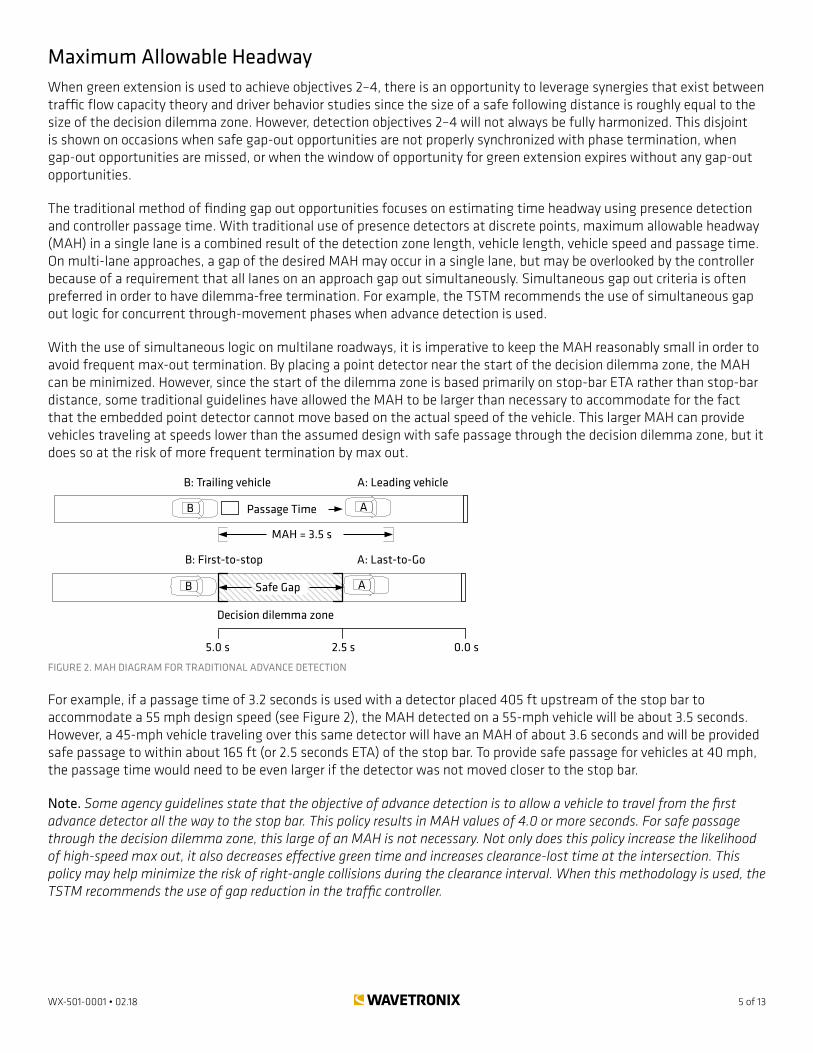
Maximum Allowable HeadwayWhen green extension is used to achieve objectives 2–4, there is an opportunity to leverage synergies that exist between traffic flow capacity theory and driver behavior studies since the size of a safe following distance is roughly equal to the size of the decision dilemma zone. However, detection objectives 2–4 will not always be fully harmonized. This disjoint is shown on occasions when safe gap-out opportunities are not properly synchronized with phase termination, when gap-out opportunities are missed, or when the window of opportunity for green extension expires without any gap-out opportunities.
The traditional method of finding gap out opportunities focuses on estimating time headway using presence detection and controller passage time. With traditional use of presence detectors at discrete points, maximum allowable headway (MAH) in a single lane is a combined result of the detection zone length, vehicle length, vehicle speed and passage time. On multi-lane approaches, a gap of the desired MAH may occur in a single lane, but may be overlooked by the controller because of a requirement that all lanes on an approach gap out simultaneously. Simultaneous gap out criteria is often preferred in order to have dilemma-free termination. For example, the TSTM recommends the use of simultaneous gap out logic for concurrent through-movement phases when advance detection is used.
With the use of simultaneous logic on multilane roadways, it is imperative to keep the MAH reasonably small in order to avoid frequent max-out termination. By placing a point detector near the start of the decision dilemma zone, the MAH can be minimized. However, since the start of the dilemma zone is based primarily on stop-bar ETA rather than stop-bar distance, some traditional guidelines have allowed the MAH to be larger than necessary to accommodate for the fact that the embedded point detector cannot move based on the actual speed of the vehicle. This larger MAH can provide vehicles traveling at speeds lower than the assumed design with safe passage through the decision dilemma zone, but it does so at the risk of more frequent termination by max out.
Phase
Controller
Backplate
Rack Card
Surge Cabinet
CTAD
Queue Detector Channel: < 35 mphAdvance Detector Channel: >35 mph
21
12
Inputs
B: Trailing vehicle A: Leading vehicle
AB Passage Time
MAH = 3.5 s
AB
1.5 s2.5 s5.0 sETAMAH = 3.5 s
PT
AB Safe Gap
165 ft330 ft
Decision dilemma zone
2.5 s5.0 s 0.0 s
A: Last-to-GoB: First-to-stop
200 ft405 ft
(@45 mph)
(@55 mph)
FIgURe 2. MAH DIAgRAM FOR TRADITIONAl ADVANCe DeTeCTION
For example, if a passage time of 3.2 seconds is used with a detector placed 405 ft upstream of the stop bar to accommodate a 55 mph design speed (see Figure 2), the MAH detected on a 55-mph vehicle will be about 3.5 seconds. However, a 45-mph vehicle traveling over this same detector will have an MAH of about 3.6 seconds and will be provided safe passage to within about 165 ft (or 2.5 seconds ETA) of the stop bar. To provide safe passage for vehicles at 40 mph, the passage time would need to be even larger if the detector was not moved closer to the stop bar.
Note. Some agency guidelines state that the objective of advance detection is to allow a vehicle to travel from the first advance detector all the way to the stop bar. This policy results in MAH values of 4.0 or more seconds. For safe passage through the decision dilemma zone, this large of an MAH is not necessary. Not only does this policy increase the likelihood of high-speed max out, it also decreases effective green time and increases clearance-lost time at the intersection. This policy may help minimize the risk of right-angle collisions during the clearance interval. When this methodology is used, the TSTM recommends the use of gap reduction in the traffic controller.

6 of 13WX-501-0001 • 02.18
CTAD CTAD is an alternative technology released subsequent to the latest edition of the Traffic Detector Handbook. A CTAD has the ability to continuously track the changing range, speed, ETA and qualified count of multiple vehicles as they approach an intersection stop bar. CTAD sensors can be programmed to signal a traffic controller to place a call to extend green only when specific criteria are met. By basing signal control on multiple criteria (see Figure 3), the effectiveness of signal control can adapt in real time to account for the dynamics in driver behavior that change as the distribution of speeds on the roadway change.
ETA
Qualified Count
Criteria MetRange
Speed
FIgURe 3. MUlTI-CRITeRIA BASeD SIgNAlINg
The benefits of CTADs have been approximated in the past by using multiple advance detectors in a series of setback distances. The TSTM highlights a multiple-detector design with as many as three setback locations on the highest speed approaches. As with CTAD detection, the increased detection coverage of a multiple-detector design allows for more responsive operations. The TSTM states:
“This design is well-suited to approaches with a significant percentage of turning vehicles because it is likely these vehicles will gap out as the vehicle slows to make the turn at the intersection or upstream driveway.”
With the continuous coverage of CTAD detection, the speed and ETA of turning vehicles is actually tracked so that green extension can be determined based upon the needs of each vehicle.
SmartSensor Advance (model SS200) is the most advanced CTAD sensor customized for traffic signal control applications. Classified as an LR-CTAD because of its long range of detection (up to 500 ft), the sensor is uniquely suited for advance detection on through movements.
Technology StackFigure 4 shows the technology stack from the CTAD physical layer to the phase layer of the traffic controller. To provide real-time updates from the physical layer, the default settings achieve a communication latency to the controller inputs of 72.5 milliseconds on average. This latency is realized over wired communication distances up to 600 ft and can be decreased by reprogramming the serial baud rate and output message push rate. Both power and dual port communications are brought to the sensor over a standard multi-conductor cable.
The CTAD physical layer is a 10.525 GHz implementation of FMCW Digital Wave Radar technology. FMCW Digital Wave Radar is a range-based, presence-sensing technology that performs consistently and accurately in harsh conditions including fog, snow, dust, rain and sun glare. The FMCW pulses are transmitted over 200 times a second and received using an elliptical antenna beam with a 70° elevation and 12° azimuth half-power bandwidth.

7 of 13WX-501-0001 • 02.18
PhaseDetector Input
Contact Closure Output
Communication layers
SafeArrival logic layers
Signal Processing layers
Physical layer
Traffic Controller
Contact Module
CTAD
Serial Input
Serial Outputs
Channel
Alert
Zone
Passing Vehicle logic
Tracked Detection Filter
RVA Tracking ModelPassage Detection
FMCW Digital Wave Radar
FIgURe 4. TeCHNOlOgY STACK
The tall elevation angle accommodates the long range of detection, while the narrow azimuth angle focuses the radar energy on the lanes of interest (see Figure 5). For approaches with more than one lane, two lanes can be detected 50 ft from the sensor, and three lanes can be detected about 100 ft from the sensor depending on the selected alignment. Consult the SmartSensor Advance User Guide for instruction on placement, mounting, alignment and sensitivity configuration. Based on the configured sensitivity, trucks, cars, motorcycles, bicycles and pedestrians can be monitored.
~50 ft
FIgURe 5. BeAM AlIgNMeNT VISUAlIZATION
Above the physical layer, the CTAD has several signal processing layers that provide for reliable tracking of vehicles even with roadside background clutter. A passage detection layer filters out stationary background objects (as well as stopped vehicles). A three-state (range, velocity and acceleration) tracking model monitors the propagation of up to 25 objects moving in sequence. A tracked detection filter helps eliminate unwanted monitoring of multipath detections or detections in the opposite direction so that the CTAD reports only objects moving in the selected traffic direction (either incoming or outgoing). A passing vehicle logic layer is also used to hold on to detections if vehicles pass each other or if they are momentarily occluded.

8 of 13WX-501-0001 • 02.18
Above the signal processing layer are SafeArrival™ Technology logic layers. The zone layer processes the estimated range, speed, ETA and qualified count of detections to determine if each zone output is active. The alert and channel layers can provide additional conditioning of the CTAD’s eight outputs before their status is transmitted via serial and contact closure communications to the traffic controller. For a detailed understanding of all the flexibility in the channel, alert and zone layers, please refer to the SmartSensor Advance User Guide.
The outputs of the contact closure cards allow for simple integration with standard TS-1, TS-2, 170, and 2070 systems. Each sensor supports up to eight detection channels, but in most advance detection applications only a single 2-channel card per sensor is necessary. In addition, the sensor protocol is an open standard for tighter integration with software programmable controllers.
SafeArrival TechnologyThe following flowchart shows the basic algorithm which is the core of SafeArrival Technology.
New radar pulse
For vehicles v=1 to 25, estimate: (1) Current range to stop line (2) Current speed (3) Current estimate time-of-arrival (ETA) to stop line
Current ETA[v] > Min&
Current ETA [v] < Max
Yes
Yes
v > 25
v = 1Qualified Count = 0
v++
Qualified Count ++
Yes
Current Speed[v] > Min&
Current Speed [v] < Max
Current Range[v] > Min&
Current Range [v] < Max
Yes
Qualified Count > Min&
Qualified Count < Max
No
No
No
Yes
No
Zone Output = True Zone Output = False
No
FIgURe 6. DeTeCTION ZONe FIlTeRINg FlOWCHART
Based upon the status of the zone outputs, the CTAD sets that state of its eight channel outputs. Each channel output is true (call active) while the selected criteria of range, speed, and ETA are satisfied for the specified number of vehicles. The output state of each channel is sent to the traffic controller at a programmable rate (default is about 10 Hz).
The zone output criteria are specified using upper and lower bounds. This specification flexibility allows for tight control of the criteria that warrant green extension in order to provide more gap out opportunities and superior prevention of high-speed max out.

9 of 13WX-501-0001 • 02.18
eTA-based extensionBy specifying a minimum and maximum ETA, a CTAD can both tightly control MAH and locate the extents of safe passage based upon actual vehicle speeds (instead of an assumed design speed). This has the efficiency benefit of equalizing MAH for vehicles at all free-flow speeds. By keeping the MAH short and tailoring the extents of safe passage to individual vehicle speeds, dilemma zone protection can actually be increased without the overprotection that commonly causes point detector–based systems to become inefficient with low-to-moderate levels of capacity usage.
In addition, ETA of a vehicle to the stop bar is the best predictor of dilemma zone incursions. ETA is a better predictor than the position or speed of the vehicle alone, and with SmartSensor Advance acceleration it also tracked in order to increase ETA accuracy. When all detected ETAs are outside the times that characterize the decision dilemma zone for a specific approach, then a safe gap in traffic has been detected.
The size of a safe gap can be defined using the sensor configuration software based on driver stopping probabilities. This allows for simple site specific customization. The nominal size of a safe gap is about 2.5 seconds, located 2.5 to 5 seconds upstream of the stop bar.
This relatively safe gap in traffic exists because multiple driver behavior studies have reported that the size of the decision dilemma zone is approximately 2.5 seconds in length. These studies report that when the light changes to yellow, 85% of drivers will attempt to clear the intersection if they are within 2.5 seconds of the intersection stop bar; and 85% of drivers will try to stop if they are more than five seconds away.
This level of certainty is also a strong deterrent to red-light running because less than 15% of drivers will attempt to clear when beyond 5 seconds from the stop bar. Even fewer will be likely to run the red light if the far boundary of the safe gap is increased to 5.5 or more seconds.
Advance Detector ChannelAn advance detector channel is configured to achieve TSTM objectives 3 and 4. This channel uses its first zone to estimate capacity usage and provide efficient dilemma zone protection. It is often recommended to use a queue detector channel in combination with the advance detector channel. The queue detector channel is promptly inhibited after vehicle speeds are detected at free-flow levels.
The advance detector channel is configured by setting minimum and maximum bounds for vehicle ETA, speed and range. Here are some suggested settings:
˿ ETA minimum = 3.0 seconds
˿ ETA maximum = 5.0 seconds
˿ Speed minimum = 35 mph
˿ Speed maximum = 100 mph
˿ Range minimum = 100 feet
˿ Range maximum = 500 feet
If any one of the vehicles on the approach is detected to meet these criteria, then the zone output will be true (and the Qualified Count will be at least 1).
For an advanced detector channel, it is usually recommended to use the phase passage timer for output extension because it has the flexibility to be used with the controller gap reduction feature if necessary. A default minimum of 1.0 seconds of phase passage time is suggested.
When used with low-speed filtering, passage time will help verify that the changes in vehicle speeds with the advance

10 of 13WX-501-0001 • 02.18
detection zone are persistent. When used with ETA detection, passage time will help extend safe passage beyond the minimum ETA specified for the advance detector channel and will help interpolate in the event of momentary detection drop-outs.
Note. Extend timers include the following: the passage timer associated with each traffic controller phase, the extend timer associated with each traffic controller input, and the extend timer associated with each CTAD channel output. It is important to determine which extend timers will be used for each application in order to prevent overextension induced by programming extension in multiple places.
By using ETA-based extension in combination with an extend timer, the MAH becomes the combination of the ETA headway and the extension time if the CTAD assumes a vehicle length of 0 ft. (By default the CTAD assumes a vehicle length of 20 ft, adding 0.25 seconds for a 55 mph vehicle.)
The following figure illustrates that with an ETA headway of 2.5 seconds and a passage time of 1.0 seconds, the resulting MAH is 3.5 seconds.
Phase
Controller
Backplate
Rack Card
Surge Cabinet
CTAD
Queue Detector Channel: < 35 mphAdvance Detector Channel: >35 mph
21
12
Inputs
B: Trailing vehicle A: Leading vehicle
AB Passage Time
MAH = 3.5 s
AB
1.5 s2.5 s5.0 sETAMAH = 3.5 s
PT
AB Safe Gap
165 ft330 ft
Decision dilemma zone
2.5 s5.0 s 0.0 s
A: Last-to-GoB: First-to-stop
200 ft405 ft
(@45 mph)
(@55 mph)
FIgURe 7. MAH DIAgRAM FOR eTA-BASeD ADVANCe DeTeCTION
Since the minimum ETA is set at 2.5 seconds and the maximum at 5.5 seconds, safe passage will be provided by the CTAD from 330 to 165 ft for a 45-mph vehicle. Then the passage timer will count down while the vehicle travels another 66 ft so that it is about 100 ft from the stop bar. For a vehicle traveling at 55 mph, safe passage will be provided by the CTAD from 405 ft to 200 ft. Then the passage timer will count down while the vehicle travels another 81 ft so that it is about 120 ft from the stop bar.
The above example serves as an illustration of what can be done to control the MAH and dilemma zone protection with a CTAD-enabled system. If the MAH needs to be smaller or larger at a particular intersection, or if dilemma zone protection warrants adjustment, customizations can be made using the configuration software.
For example, on trucking corridors it may be more appropriate to set the ETA bounds from 6.5 down to 3.5 seconds and specify 1 second of passage time. This would result in a MAH of about 4 seconds and justify the use of gap reduction.
The SmartSensor Advance – SafeArrival Technology brochure illustrates how CTAD dilemma zone protection provides added priority for high-momentum vehicles like trucks and buses. In fact, if the intersections along the corridor are actuated, all standard controllers can be programmed to incrementally increase priority for large high-speed vehicles (when compared to smaller high-speed vehicles). This can be done using the gap-reduction feature. Near the beginning of green, a sizable amount of passage time can be used to prevent momentary occlusion of small vehicles from causing gap out. But then as the green time persists and no dilemma-free condition has been detected, the passage time can be decreased to favor termination with a small high-speed vehicle in the dilemma zone, as opposed to a large high-speed vehicle that may be occluding it.

11 of 13WX-501-0001 • 02.18
Dynamic Dilemma Zone ProtectionSince the advance detector channel uses ETA detection, it provides a dynamic form of dilemma zone protection that has both safety and efficiency benefits. As speeds increase, the need for high-speed protection moves further back on the approach. In addition, the size of a safe gap in traffic necessary to safely terminate a phase also grows. Conversely, when speeds decrease, the size of a safe gap shrinks, and its location on the roadway moves closer to the stop bar.
With SmartSensor Advance, high-speed protection can be actively adjusted as far away as 500 ft from the sensor. This dynamic zone placement and sizing based upon ETA provides additional safety when speeds reach their most dangerous levels, especially when compared to a single point detector located about 300 or 400 ft upstream of the stop bar.
60mph
500 ft 100 ft
500 ft 100 ft
500 ft 100 ft
50mph
40mph40mph 40mph
50mph50mph
60mph 60mph
Stop Bar
Stop Bar
Stop Bar
Safe Gap
Safe Gap
Safe Gap
5 sec. 3 sec.
5 sec. 3 sec.
5 sec. 3 sec.
FIgURe 8. PROTeCTION AUTOMATICAllY ADJUSTS FOR SPeeD
Dynamic dilemma zone protection based upon ETA simplifies and validates design of advance detection. No longer do point detectors need to be relocated when the 85th percentile or posted speeds on an approach change.
Max-out PreventionIn order for an advance detection system to be most effective it must minimize the number of cycles required to max out the traffic phase with high-speed vehicles in the dilemma zone. During moderate levels of congestion this can be very challenging for systems that use embedded presence detectors at discrete point locations. Inherently, embedded presence detectors do not have the ability to (1) dynamically change zone placement, and (2) detect vehicle speed.
With CTAD advance detector channels, calls for green extension can be constrained, using ETA, to situations where vehicles are over the areas of the roadway that need to be protected. If a leading vehicle is traveling fast and a following vehicle is traveling slowly, this area of protection can be very small (see SmartSensor Advance – SafeArrival Technology Brochure).
Furthermore, when speeds drop to lower levels during moderate congestion, the use of speed-based detection will decrease the likelihood of terminating the phase by max out. With CTAD detection, green extension can be limited to vehicles traveling above a critical speed (e.g. 35 mph). This means that if speed drops low enough, green extension is no longer critical for safety, and the intersection can be controlled primarily based upon the theories of capacity flow through an intersection rather than driver behavior.
effective green-time RecoveryOne benefit of ETA-based advance detection is that it reliably predicts which motorists will go through the light even after it turns yellow. When a phase terminates by gap out with a vehicle 2.5 seconds away from the stop bar, this driver will have an 85% probability of clearing the intersection. In addition, any drivers ahead of this vehicle are also very likely to clear the intersection. Some traffic researchers claim that the light is effectively green for these drivers within 2.5 seconds of the stop bar.

12 of 13WX-501-0001 • 02.18
Consider that if stop-bar detection is used instead of advance detection, this extra-effective green time is not realized. In fact, with stop bar–only detection, it is actually expected that no vehicles will cross the stop bar in the last few seconds of green. So in comparison to stop-bar detection, a CTAD advance detection channel can regularly increase effective green time near the clearance interval transition from 2.5 to 5.0 seconds. And in comparison to other forms of advance detection, CTAD sensors do a better job of tracking arriving vehicles in order to help increase effective green time across a broad range of high speeds.
Queue Detector ChannelOften high-speed through movements are on minimum recall. Since these major movements are automatically called by the controller, there is no need for stop-bar detectors in these lanes. However, in some cases stop-bar detection is used to call minor high-speed through movements. On these minor movements the TSTM recommends programming the stop-bar detectors as queue detectors so that they disconnect after detection objective 2 is satisfied.
If you already have stop-bar detection on your high-speed approaches, you may not need to use the CTAD to achieve TSTM objective 2. However, configuring a queue detector channel with the CTAD can be very cost-effective for through movements on recall because stop-bar detection is no longer necessary.
The queue detector channel can be configured using the first zone of the second channel of the CTAD. With the passage timer set at 1.0 seconds, this zone is configured to extend green with MAH of 2.6 seconds for vehicles traveling at 30 mph. The detection range of the zone can be 100 to 150 ft from the stop bar. A vehicle traveling at 30 mph will activate this 50-ft zone for approximately 1.6 seconds (with the default vehicle length set at 20 ft). Slower vehicles will experience a larger MAH which is useful during the startup period of queue dissipation.
The queue detector channel’s zone will not use ETA criteria or discriminate based on qualified count, but it will use speed in order to inhibit the detector once free flow is reached on the high-speed movement. To do this the minimum speed bound will be set at 1 mph and the maximum speed bound will be set at 35 mph. Speed-based deactivation of the queue clearance channel is used instead of programming the associated controller detector input as a queue-detector type.
By placing the zone about 100 ft back from the stop bar, you can get the benefits of setback detection. With setback detection, green extension is performed for vehicles that are still approaching the intersection, rather than vehicles that are already at the intersection. This setup helps recover some of the lost time between traffic phases, in the event that free-flow speeds are not reached on the high-speed approach.
When free-flow speeds are reached, the CTAD will stop signaling calls on the queue detector channel and start signaling calls on the advance detector channel. This speed-based deactivation and activation of channels is unique to a CTAD and is not something you get with embedded point detector systems. With embedded systems the queue detector channel will sometimes remain active and errantly force max out long after high-speeds are reached.
It is possible to decrease the size of the zone and increase the extension time if necessary on a particular approach. However, remember that once a queue detector channel is assigned to a phase it inherits that base amount of extension time. So if the phase passage timer is set to 1.0 seconds and an additional 1.0 seconds is added to the controller input extend timer, then the total extension time experienced by queue detector channel will be 2.0 seconds (and the MAH would be even greater depending on the zone size).
Normally, it is not recommended to configure the controller so that CTAD’s queue detector channel will disconnect. Rather, the channel will be inhibited when speeds rise to free-flow level (e.g. 35 mph).
Minimum greenThe TSTM provides guidance on setting the minimum green time for different types of facilities. On a major arterial, 10 to 15 seconds of minimum green time is necessary to satisfy driver expectancy. The TSTM also indicates that 15 seconds is sufficient green time for the queue to clear when the nearest upstream detector is 126 to 150 ft from the stop bar.

13 of 13
© 2018 Wavetronix LLC. All rights reserved. Protected in the US by patents viewable at www.wavetronix.com/en/legal. Protected by Canadian Patent Nos. 2461411; 2434756; 2512689; and European Patent Nos. 1435036; 1438702; 1611458. Other US and international patents pending. Wavetronix, SmartSensor, Click, Command and all associated logos are trademarks of Wavetronix LLC. All other product or brand names as they appear are trademarks or regis-tered trademarks of their respective holders. Product specifications are subject to change without notice. This material is provided for informational purposes only; Wavetronix assumes no liability related to its use.
WX-501-0001 • 02.18
Since the CTAD is a passage detector, it is recommended that the minimum green time be 15–20 seconds when used on a major arterial without stop-bar detectors. This will allow sufficient time for the vehicles that were stopped in the range of the queue clearance detector to begin moving.
It is also possible to use the CTAD’s advance detection channel to activate volume-density functions that help adjust the initial green. However, when configuring these functions, keep in mind that the CTAD’s advanced detection channel has not been configured for volume counting and will appear to under count. In essence the channel will merge closely following vehicles because its output remains active as long as there is at least one vehicle that satisfies the specified criteria. To reduce under counting you may chose to reduce the ETA headway by increasing the minimum ETA bound. However, you will want to remember to increase the passage time if you want to maintain the same MAH.
If you are using the CTAD on a high-speed minor movement, it is likely that you will have stop-bar detectors to call the phase. If you do not, it is possible to mount the CTAD to detect vehicles at the stop bar. This will allow you to place the queue detector channel’s zone right at the stop bar so that the minimum green time can be reduced. In this case you may also be able to use a latched channel to call the phase (see the SmartSensor Advance User Guide for more information on latched channels).
For questions regarding the maximum green time and other signal timing questions, consult the TSTM.
Hardware IntegrationWavetronix supplies a SmartSensor Basic Preassembled Traffic Cabinet backplate, Click contact closure modules, SmartSensor cable, and SmartSensor Pole-mount Surge Preassembled Cabinets for hassle-free integration of SmartSensor Advance into your signalized intersection. For more information on the integration process, consult the SmartSensor Advance Quick-start Guide, the SmartSensor Advance User Guide and the Wavetronix Product Catalog.
Device SpecificationsFor large vehicles like truck trailers, CTAD detection accuracy often exceeds 95% and the nominal detection accuracy is 90% for all vehicles within the first 400 ft (see Figure 9). The detection accuracy drops off at further ranges depending upon the mounting height, vehicle type and lead-vehicle occlusion. Multiple detections of large vehicles like truck-trailer combinations are common and useful.
Range of earliest detection (feet)
100%
90%
80%
70%
60%
50%
40%
30%
20%
10%
0%100 200 300 400 500 600
Trucks/TrailersNon-Truck/Trailers
Prop
ortio
n of
veh
icle
s
FIgURe 9. RANge OF DeTeCTION gRAPH
The nominal mean time of failure for the SmartSensor Advance is 10 years. It can be purchased with a 5-year warranty option. The CTAD is constructed with solid state electronics and has no batteries. For more information and up-to-date specifications related to CTAD accuracy consult the SmartSensor Advance datasheet.