adv200 - welcome to amicon drive systems,...
TRANSCRIPT

.... Functions description and parameters list
SIEI
Driv
eField oriented vector AC Drive
ADV200
� ADV200 • Functions description and parameters list
Informationaboutthismanual
This manual explains the functions and the description of the parameters.The informations about mechanical installation, electrical connection and fast start-up can be found on the ADV200 Quick start guide. The whole set of manuals (included the expansions and field bus manuals) can be found on the CD provided with the dirve.
SoftwareversionThis manual is updated according the software version V 1.0XX.Variation of the number replacing “X” have no influence on the functionality of thedevice.
The identification number of the software version is indicated on the identification plate of the drive or can be checked with the Firmware ver.rel - PAR 490 parameter, menu 2.5.
Generalinformation
Note ! In industry, the terms “Inverter”, “Regulator” and “Drive” are sometimes interchanged. In this document, the term “Drive” will be used.
Before using the product, read the safety instruction section carefully. Keep the manual in a safe place and available to engineering and installation personnel during the product functioning period.Gefran S.p.A has the right to modify products, data and dimensions without notice. The data can only be used for the product description and they can not be understood as legally stated properties.
Thank you for choosing this Gefran product.We will be glad to receive any possible information which could help us improvingthis manual. The e-mail ad-dress is the following: [email protected] rights reserved

ADV200 • Functions description and parameters list �
TableofContents
Informationaboutthismanual..................................................................................................................�Symbols used in the manual...................................................................................................................................4
A–Programming.......................................................................................................................................5A.1 Menu display modes ........................................................................................................................................5A.2 Programming of “function block” analog and digital input signals ....................................................................5A.3 Variable interconnections mode .......................................................................................................................5
B–Parametersandfunctionsdescription(Expertlist).........................................................................7Legend ....................................................................................................................................................................71 – MONITOR .........................................................................................................................................................82 – DRIVE INFO ...................................................................................................................................................113 – STARTUP WIZARD ........................................................................................................................................144 – DRIVE CONFIG ..............................................................................................................................................155 – REFERENCES ...............................................................................................................................................206 – RAMPS ...........................................................................................................................................................277 – MULTI REFERENCE ......................................................................................................................................318 – MOTORPOTENTIOMETER ...........................................................................................................................349 – JOG FUNCTION .............................................................................................................................................4110 – SPEED MONITOR FUNC .............................................................................................................................4211 – COMMANDS .................................................................................................................................................4512 – DIGITAL INPUTS .........................................................................................................................................5313 – DIGITAL OUTPUTS ......................................................................................................................................5514 – ANALOG INPUTS .........................................................................................................................................5715 – ANALOG OUTPUTS ....................................................................................................................................6616 – MOTOR DATA ...............................................................................................................................................7117 – ENCODER CONFIG .....................................................................................................................................7518 – SPEED REG GAINS.....................................................................................................................................7719 – REGULATOR PARAM ..................................................................................................................................8020 – TORQUE CONFIG .......................................................................................................................................8421 – FV PARAMETERS ........................................................................................................................................8722 – FUNCTIONS .................................................................................................................................................93
22.1 – FUNCTIONS/SPEED RATIO .....................................................................................................................................9322.2 – FUNCTIONS/DROOP ...............................................................................................................................................9322.3 – FUNCTIONS/INERTIA COMP ...................................................................................................................................9522.4 – FUNCTIONS/DC BRAKING ......................................................................................................................................9622.5 – FUNCTIONS/MOTOR OVERLOAD ..........................................................................................................................9822.6 – FUNCTIONS/BRES OVERLOAD ..............................................................................................................................9822.7 – FUNCTIONS/DOUBLE PAR SET ..............................................................................................................................9922.8 – FUNCTIONS/SPEED CAPTURE ............................................................................................................................10122.9 – FUNCTIONS/POWER LOSS ..................................................................................................................................10222.10 – FUNCTIONS/COMPARE .......................................................................................................................................10522.11 – FUNCTIONS/PADS ...............................................................................................................................................107
23 – COMMUNICATION .....................................................................................................................................10823.1 – COMMUNICATION/RS485 ......................................................................................................................................10823.2 – COMMUNICATION/FIELDBUS CONFIG ...............................................................................................................10923.3 – COMMUNICATION/FIELDBUS M2S ...................................................................................................................... 11123.4 – COMMUNICATION/FIELDBUS S2M ....................................................................................................................... 11323.5 – COMMUNICATION/WORD COMP.......................................................................................................................... 11623.6 – COMMUNICATION/WORD DECOMP..................................................................................................................... 117
24 – ALARM CONFIG .........................................................................................................................................11825 – ALARM LOG ...............................................................................................................................................12726 – APPLICATION ............................................................................................................................................128PARAMETERS ON SELECTION LISTS, BUT NOT DISPLATED ON KEYPAD ...............................................129
C–SELECTIONLISTS...........................................................................................................................1�6L_ANOUT ...........................................................................................................................................................................136L_CMP ................................................................................................................................................................................136L_DIGSEL1 ........................................................................................................................................................................137L_DIGSEL2 ........................................................................................................................................................................137L_DIGSEL3 ........................................................................................................................................................................137L_FBS2M ............................................................................................................................................................................138L_LIM ..................................................................................................................................................................................139L_MLTREF .........................................................................................................................................................................139L_REF ................................................................................................................................................................................139L_SCOPE ...........................................................................................................................................................................140L_VREF ..............................................................................................................................................................................140L_WDECOMP ....................................................................................................................................................................140
D–TROUBLESHOOTING......................................................................................................................141E–MESSAGES......................................................................................................................................146
4 ADV200 • Functions description and parameters list
Symbolsusedinthemanual
Indicates a procedure, condition, or statement that, if not strictly observed, could result in personal injury or death.Indique le mode d’utilisation, la procédure et la condition d’exploitation. Si ces consignes ne sont passtricte-ment respectées, il y a des risques de blessures corporelles ou de mort.
Indicates a procedure, condition, or statement that, if not strictly observed, could result in damage to or destruc-tion of equipment.Indique et le mode d’utilisation, la procédure et la condition d’exploitation. Si ces consignes ne sont pas stricte-ment respectées, il y a des risques de détérioration ou de destruction des appareils.
Indicates that the presence of electrostatic discharge could damage the appliance. When handling the boards, always wear a grounded bracelet.Indique que la présence de décharges électrostatiques est susceptible d’endommager l’appareil. Toujours porter un bracelet de mise à la terre lors de la manipulation des cartes.
Indicates a procedure, condition, or statement that should be strictly followed in order to optimize these applica-tions.Indique le mode d’utilisation, la procédure et la condition d’exploitation. Ces consignes doivent êtrerigoureuse-ment respectées pour optimiser ces applications.
Note ! Indicates an essential or important procedure, condition, or statement. Indiqueunmoded’utilisation,deprocédureetdeconditiond’exploitationessentielsouimportants
WarningWarning
CautionCaution
ImportantImportant
F-BlòckDiagrams.................................................................................................................................149MPot ...................................................................................................................................................................149Jog ......................................................................................................................................................................150Ramp Ref - Reference skip ................................................................................................................................151Ramp ..................................................................................................................................................................152FRC ....................................................................................................................................................................153Multi Reference ...................................................................................................................................................154Speed Reference ................................................................................................................................................155Speed Zero .........................................................................................................................................................156Gain Adapt ..........................................................................................................................................................157Analog Inpus Standard .......................................................................................................................................158Analog Outputs ...................................................................................................................................................159Digital Inputs .......................................................................................................................................................160Digital Outputs ....................................................................................................................................................161Commands .........................................................................................................................................................162DC Braking .........................................................................................................................................................163Analog Inputs Expansion Card ...........................................................................................................................164Torque control - flux vector CL/OL ......................................................................................................................165Control V/F ..........................................................................................................................................................166Inertia Compensation..........................................................................................................................................167Compare .............................................................................................................................................................168Speed Monitor Function......................................................................................................................................169Droop ..................................................................................................................................................................170Power loss ..........................................................................................................................................................171
ADV200 • Functions description and parameters list 5
A–Programming
A.1Menudisplaymodes
The programming menu can be displayed in two modes, which can be selected using the Accessmode pa-rameter (04 - DRIVE CONFIG menu): • Easy(default) only the main parameters are displayed.• Expert all the parameters are displayed A.�Programmingof“functionblock”analoganddigitalinputsignals
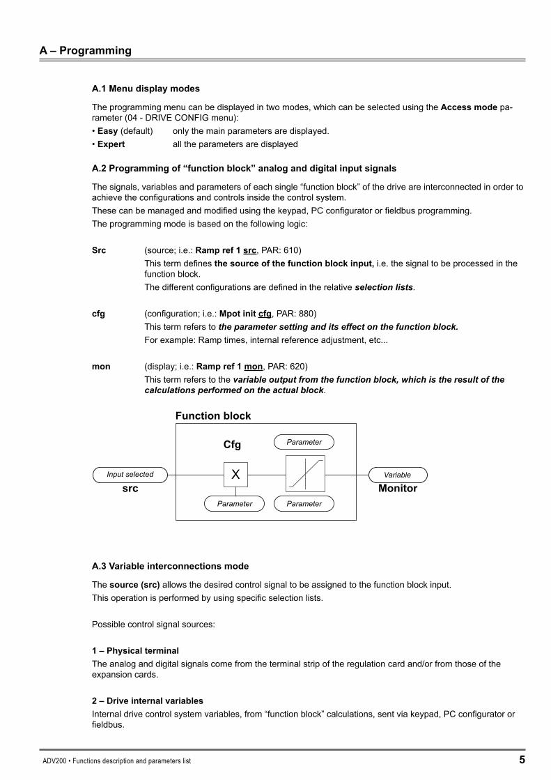
The signals, variables and parameters of each single “function block” of the drive are interconnected in order to achieve the configurations and controls inside the control system.These can be managed and modified using the keypad, PC configurator or fieldbus programming.The programming mode is based on the following logic:
Src (source; i.e.: Rampref1src, PAR: 610) This term definesthesourceofthefunctionblockinput, i.e. the signal to be processed in the
function block. The different configurations are defined in the relative selection lists.
cfg (configuration; i.e.: Mpotinitcfg, PAR: 880) This term refers to the parameter setting and its effect on the function block. For example: Ramp times, internal reference adjustment, etc...
mon (display; i.e.: Rampref1mon, PAR: 620) This term refers to the variable output from the function block, which is the result of the
calculations performed on the actual block.
Input selected
Parameter
Parameter
Parameter
Variable
Cfg
src Monitor
Function block
A.�Variableinterconnectionsmode
Thesource(src) allows the desired control signal to be assigned to the function block input. This operation is performed by using specific selection lists.
Possible control signal sources:
1–PhysicalterminalThe analog and digital signals come from the terminal strip of the regulation card and/or from those of the expansion cards.
�–DriveinternalvariablesInternal drive control system variables, from “function block” calculations, sent via keypad, PC configurator or fieldbus.

6 ADV200 • Functions description and parameters list
PracticalexampleThe following examples illustrate the philosophies and methods with which more or less complex operations are performed in the single “function blocks”, the results of which represent the output of the block.
• Example: Changing the Speed Reference sourceThe main drive reference (in the default configuration) Rampref1mon(PAR: 620) is generated by the output of the function block “RampsetpointBlock”.
Its default source is the Analoginput1mon signal (PAR: 1500), from the output of the function block “Analoginput1Block”, which in this case refers to analog input 1 of the signal terminal strip.
To change the reference source from the analog input to a digital reference inside the drive, the input signal must be changed to “RampsetpointBlock”.
Enter the Rampref1srcparameter (PAR: 610)and set a new reference, selecting it from among those listed in the L_MLTREF selection list, for example Digrampref1(PAR: 600).
• Example: Inverting the analog reference signalTo invert the “Analoginput1Block” output signal, the value of the Aninp1signsrcparameter (PAR: 1526), which has a default setting of Null (no operation), must be changed by selecting the source of the command signal from among those listed in the L_DIGSEL 2 selection list, for example DigitalinputXmon, One(func-tion always enabled), etc.
+1
-1
* -1
* +1
Null
Null
An inp 1 sign srcNull An inp 1 alt sel src
Analog input 1 monAnalog input 1 Block
Ramp Setpoint Block
Terminal input
Ramp ref 1 monRamp ref 1 src
An inp 1 alt value
Ramp ref invert src
The diagrams above illustrate the internal processing philosophy of the single “function blocks” and the result of these changes on the other interconnected “function blocks”.
Note ! This section contains a brief description of the functions of the other parameters in the function blocks not included for the changes in the example
The Aninp1altselsrc parameter (PAR: 1528) can be used to select an alternative reference for the Analoginput1mon(PAR: 1500) output.The Aninp1altvalueparameter (PAR: 1524) determines the alternative reference value for the Analoginput1mon(PAR: 1500) output.The Ramprefinvertsrc parameter (PAR: 616) can be used to select the source for the command to reverse the “Rampsetpoint” function block output.The output signal from the “Rampsetpoint” block is displayed in the Rampref1monparameter (PAR: 620).

ADV200 • Functions description and parameters list 7
B–Parametersandfunctionsdescription(Expertlist)
Legend
Menu PAR Description UM Type FB BIT Def Min Max Acc Mod
1-MONITOR1.1 250 Outputcurrent A FLOAT 16/32 0.0 0.0 0.0 R FVS1.2 252 Outputvoltage V FLOAT 16/32 0.0 0.0 0.0 R FVS
��.1-FUNCTIONS/SPEEDRATIO22.01.01 3000 Digspeedratio perc INT16 16/32 100 50 200 ERW FVS22.01.02 3002 Speedratiosrc LINK 16/32 3000 0 16384 ERW FVS L_VREF (SelectionList)[*]
(Level1menu)
(Level2menu)
Indexing of the menu and parameter
Parameter identifier
Parameter description
UM: unit of measure
Type of parameter
BIT Boolean, from modbus seen as 16 bitsENUM Selection list, from modbus seen as 16 bitsFLOAT Real, from modbus seen as 32 bitsINT16 Integer with sign 16 bits, from modbus seen as 16 bitsINT32 Integer with sign 32 bits, from modbus seen as 32 bitsILINK Selection list, from modbus seen as 16 bitsLINK Selection list, from modbus seen as 16 bitsUINT16 Integer without sign 16 bits, from modbus seen as 16 bitsUINT32 Integer without sign 32 bits, from modbus seen as 32 bits
Format of data exchanged on Fieldbus (16BIT, 32BIT)
Default value
Minimum value
Maximum value
Accessibility :E ExpertR ReadS Size (set value depending on the size of the device)W WriteZ parameters that can be modified ONLY with the drive disabled
Available in regulation mode:V = V/f ControlS = Vect Flux OLF = Vect Flux CL
[*]
Selectionlists:The “... src” format parameters are linked to a selection list. The source of the signal that will control the parameter can be selected from the list indicated.The lists are indicated in paragraph C of this manual.

� ADV200 • Functions description and parameters list
1–MONITORThe monitor menu displays the measured values of the sizes and of the drive operating parameters..
Menu PAR Description UM Type FB BIT Def Min Max Acc Mod
1.1 250 Outputcurrent A FLOAT 16/32 0.0 0.0 0.0 R FVSThe drive output current is displayed.
Menu PAR Description UM Type FB BIT Def Min Max Acc Mod
1.2 252 Outputvoltage V FLOAT 16/32 0.0 0.0 0.0 R FVSThe drive line voltage output is displayed.
Menu PAR Description UM Type FB BIT Def Min Max Acc Mod
1.3 254 Outputvoltage Hz FLOAT 16/32 0 0 0 R FVSThe drive output voltage is displayed.
Menu PAR Description UM Type FB BIT Def Min Max Acc Mod
1.4 628 Rampsetpoint rpm INT16 16/32 0 0 0 R FVSThe ramp reference is displayed. This is the speed value the drive must reach at the end of the ramp.
Menu PAR Description UM Type FB BIT Def Min Max Acc Mod
1.5 664 Speedsetpoint rpm INT16 16/32 0 0 0 R FVSThe speed reference is displayed. This is the value measured at the output of the speed reference circuit.
Menu PAR Description UM Type FB BIT Def Min Max Acc Mod
1.6 260 Motorspeed rpm INT16 16/32 0 0 0 R FVSThe actual output speed of the motor is displayed.
Menu PAR Description UM Type FB BIT Def Min Max Acc Mod
1.7 270 DClinkvoltage V FLOAT 16/32 0.0 0.0 0.0 ER FVSThe direct voltage of the intermediate circuit capacitors is displayed (DC-Bus).
Menu PAR Description UM Type FB BIT Def Min Max Acc Mod
1.8 272 Heatsinktemperature degC INT16 16 0 0 0 ER FVSThe temperature measured on the drive heatsink is displayed.
Menu PAR Description UM Type FB BIT Def Min Max Acc Mod
1.9 280 Torquecurrentref A FLOAT 16/32 0.0 0.0 0.0 ER F_SThe current reference used for torque control is displayed (in the sensorless vector and field-oriented vector modes).
Menu PAR Description UM Type FB BIT Def Min Max Acc Mod
1.10 282 Magnetcurrentref A FLOAT 16/32 0.0 0.0 0.0 ER F_SThe magnetizing current reference is displayed (in the sensorless vector and field-oriented vector modes).
Menu PAR Description UM Type FB BIT Def Min Max Acc Mod
1.11 284 Torquecurrent A FLOAT 16/32 0.0 0.0 0.0 ER FVSThe actual torque current value is displayed.

ADV200 • Functions description and parameters list 9
Menu PAR Description UM Type FB BIT Def Min Max Acc Mod
1.12 286 Magnetcurrent A FLOAT 16/32 0.0 0.0 0.0 ER FVSThe actual magnetizing current value is displayed.
Menu PAR Description UM Type FB BIT Def Min Max Acc Mod
1.13 3212 Motoroverloadaccum perc UINT16 16/32 0 0 100 ER FVSThe motor overload level is displayed (100% = alarm threshold).
Menu PAR Description UM Type FB BIT Def Min Max Acc Mod
1.14 368 Driveoverloadaccum perc UINT16 16/32 0 0 100 ER FVSThe drive overload level is displayed. An instantaneous overload of 180% of the drive rated current is allowed for 0.5s. The thermal image I²t adjusts the drive output current thresholds. During normal operation, the instan-taneous output current value can reach 180% of the drive rated current. After 0.5s at 180%, the output current threshold is reduced to 150%. When the overload level par.�6�Driveoverloadaccum reaches 100%, the output current threshold is reduced to 100% of the rated current, and stays at that value until the I²t integrator cycle is complete. At this point the 180% instantaneous overload is re-enabled.
Menu PAR Description UM Type FB BIT Def Min Max Acc Mod
1.15 3260 Bresoverloadaccum perc UINT16 16/32 0 0 100 ER FVSThe braking resistor overload limit is displayed (100% = alarm threshold).
Menu PAR Description UM Type FB BIT Def Min Max Acc Mod
1.16 1066 Enablestatemon BIT 16 0 0 1 R FVSThe drive Enable command status is displayed. Voltage must be present on terminal 7. The FR Forwardstart command is needed to start the inverter.
0 Disableddrive disabled1 Enableddrive enabled
Menu PAR Description UM Type FB BIT Def Min Max Acc Mod
1.17 1068 Startstatemon BIT 16 0 0 1 R FVSThe drive Start command status is displayed.
Menu PAR Description UM Type FB BIT Def Min Max Acc Mod
1.18 1070 FastStopstatemon BIT 16 0 0 1 R FVSThe drive FastStop command status is displayed.
Menu PAR Descripttion UM Type FB BIT Def Min Max Acc Mod
1.19 1100 Digitalinputmon UINT16 16 0 0 0 R FVSThe status of the digital inputs on the drive is displayed. It can also be read via a serial line or fieldbus. The data are contained in a word, where each bit is 1 if voltage is supplied to the corresponding input terminal.
1 Input enabled.0 Input disabled.
I.e. :
000000000011
Attivo DI 1Attivo DI 2

10 ADV200 • Functions description and parameters list
Menu PAR Description UM Type FB BIT Def Min Max Acc Mod
1.20 1300 Digitaloutputmon UINT16 0 0 0 R FVSThe status of the digital outputs on the drive is displayed. It can also be read via a serial line or fieldbus. The data are contained in a word, where each bit is 1 if voltage is supplied to the corresponding input terminal.
1 Output enabled.0 Output disabled.
I.e. :
000000000011
Attiva DO 1Attiva DO 2
Menu PAR Description UM Type FB BIT Def Min Max Acc Mod
1.21 1200 DigitalinputXmon UINT16 16 0 0 0 R FVSThe status of the digital inputs of the expansion card is displayed. It can also be read via a serial line or field-bus. The data are contained in a word, where each bit is 1 if voltage is supplied to the corresponding input terminal.
1 Input enabled.0 Input disabled.
I.e. :
000000000011
Attivo DI 1Attivo DI 2
Menu PAR Description UM Type FB BIT Def Min Max Acc Mod
1.22 1400 DigitaloutputXmon UINT16 0 0 0 R FVSThe status of the digital outputs of the expansion card is displayed. It can also be read via a serial line or fieldbus. The data are contained in a word, where each bit is 1 if voltage is supplied to the corresponding input terminal.
1 Output enabled.0 Output disabled.
I.e. :
000000000011
Attiva DO 1Attiva DO 2

ADV200 • Functions description and parameters list 11
�–DRIVEINFOThis menu displays the information for identifying and configuring the drive.
Menu PAR Description UM Type FB BIT Def Min Max Acc Mod
2.1 482 Drivesize UINT16 No Power 0 0 RThe drive size identification code is displayed.
Menu PAR Description UM Type FB BIT Def Min Max Acc Mod
2.2 484 Drivefamily ENUM No Power 0 0 RS FVSThe available mains voltage is displayed (e.g. 400V). The undervoltage alarm refers to this voltage value.The condition Ness power occurs when the regulation board has just left from production and has never been configured for any power. The configuration adjustment for a given power is achieved by linking it to a power board and running a Saveparameters.
0 No Power1 380V…480V� 500V…575V� 690V4 230V
Menu PAR Description UM Type FB BIT Def Min Max Acc Mod
2.3 486 Driveregion ENUM EU 0 1 R FVSSetting of the geographical area in which the drive is to be used (Europe or USA). This setting determines the factory voltage and power supply frequency values (e.g. when set to 0 the default voltage is 400V and frequen-cy 50Hz).
0 EU1 USA
Menu PAR Description UM Type FB BIT Def Min Max Acc Mod
2.4 488 Drivecontcurrent A FLOAT CALCF 0.0 0.0 RZS FVSThe current that the drive can deliver continuously according to size, supply voltage and programmed switching frequency is displayed.
Menu PAR Description UM Type FB BIT Def Min Max Acc Mod
2.5 490 Firmwarever.rel UINT16 0 0 0 R FVSThe version number and release number of the drive firmware are displayed. On the keypad these are dis-played in the version.release format. The parameter reading from the serial communication device or fieldbus returns the version in the high byte and the release in the low byte.
Menu PAR Description UM Type FB BIT Def Min Max Acc Mod
2.6 496 Firmwaretype UINT16 0 0 0 R FVSThe type of firmware installed in the drive is displayed.
Menu PAR Description UM Type FB BIT Def Min Max Acc Mod
2.7 504 Applicationver.rel UINT16 0 0 0 ER FVSThe version number and release number of the application are displayed.
Menu PAR Description UM Type FB BIT Def Min Max Acc Mod
2.8 506 Applicationtype UINT16 0 0 0 ER FVSThe type of application currently used by the drive is displayed.
1� ADV200 • Functions description and parameters list
Menu PAR Description UM Type FB BIT Def Min Max Acc Mod
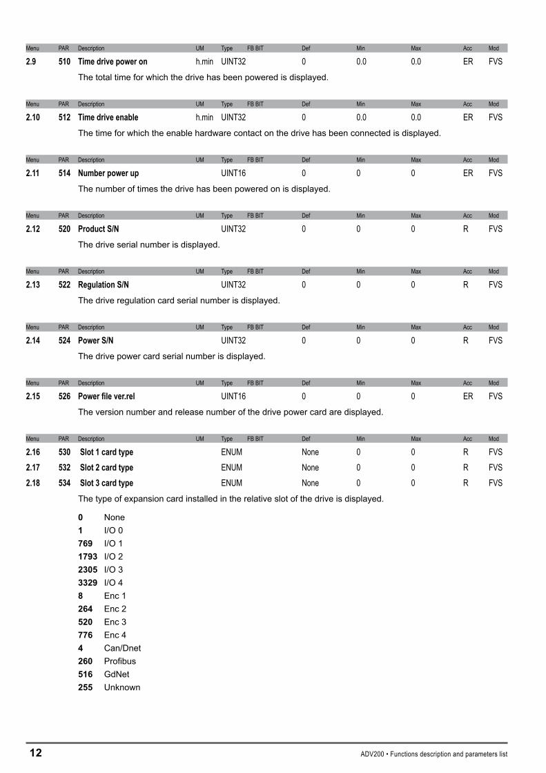
2.9 510 Timedrivepoweron h.min UINT32 0 0.0 0.0 ER FVSThe total time for which the drive has been powered is displayed.
Menu PAR Description UM Type FB BIT Def Min Max Acc Mod
2.10 512 Timedriveenable h.min UINT32 0 0.0 0.0 ER FVSThe time for which the enable hardware contact on the drive has been connected is displayed.
Menu PAR Description UM Type FB BIT Def Min Max Acc Mod
2.11 514 Numberpowerup UINT16 0 0 0 ER FVSThe number of times the drive has been powered on is displayed.
Menu PAR Description UM Type FB BIT Def Min Max Acc Mod
2.12 520 ProductS/N UINT32 0 0 0 R FVSThe drive serial number is displayed.
Menu PAR Description UM Type FB BIT Def Min Max Acc Mod
2.13 522 RegulationS/N UINT32 0 0 0 R FVSThe drive regulation card serial number is displayed.
Menu PAR Description UM Type FB BIT Def Min Max Acc Mod
2.14 524 PowerS/N UINT32 0 0 0 R FVSThe drive power card serial number is displayed.
Menu PAR Description UM Type FB BIT Def Min Max Acc Mod
2.15 526 Powerfilever.rel UINT16 0 0 0 ER FVSThe version number and release number of the drive power card are displayed.
Menu PAR Description UM Type FB BIT Def Min Max Acc Mod
2.16 530 Slot1cardtype ENUM None 0 0 R FVS2.17 532 Slot2cardtype ENUM None 0 0 R FVS2.18 534 Slot3cardtype ENUM None 0 0 R FVS
The type of expansion card installed in the relative slot of the drive is displayed.
0 None1 I/O 0769 I/O 1179� I/O 2��05 I/O 3���9 I/O 4� Enc 1�64 Enc 25�0 Enc 3776 Enc 44 Can/Dnet�60 Profibus516 GdNet�55 Unknown

ADV200 • Functions description and parameters list 1�
Menu PAR Description UM Type FB BIT Def Min Max Acc Mod
2.19 536 Slot1cardS/N UINT32 0 0 0 R FVS2.20 538 Slot2cardS/N UINT32 0 0 0 R FVS2.21 540 Slot3cardS/N UINT32 0 0 0 R FVS
The serial number of the expansion card installed in the relative slot of the drive is displayed.

14 ADV200 • Functions description and parameters list
�–STARTUPWIZARDThe startup wizard menu suggests a procedure for commissioning the drive quickly with a reduced number of settings. Advanced customization requires the use of the single parameters relating to the specific performance levels. See the procedure described in the previous Startupwizard chapter.

ADV200 • Functions description and parameters list 15
4–DRIVECONFIG
Menu PAR Description UM Type FB BIT Def Min Max Acc Mod
4.1 550 Saveparameters BIT 0 0 1 RW FVSAny changes to parameter values immediately affect drive operations, but are not automatically saved in the permanent memory.The “Save Parameters” command is used to save current parameter values in the permanent memory.Any changes that are not saved will be lost when the drive is switched off.To save parameters follow the procedure described in STEP6 of the Startupwizard.
Menu PAR Description UM Type FB BIT Def Min Max Acc Mod
4.2 552 Regulationmode ENUM V/f control 0 3 RWZ FVSThe ADV200 is capable of operating with different control modes:
0 V/f control1 Flux vector OL� Flux vector CL� Autotune
The open loopV/f(V/fcontrol) mode is the simplest type of asynchronous motor control, as the only param-eters required are the rated voltage, current and frequency of the motor.The open loop V/F control mode is factory-set and does not require any speed feedback. The natural varia-tion in speed generated by machine load induction (slippage) can be compensated using Slipcomp and Slipcomp filter.In V/f mode a single drive can be used to control several asynchronous motors, even of different sizes, con-nected in parallel, provided the sum of the currents of the single motors is less than the drive rated current. If using several motors connected in parallel, be sure to provide adequate thermal protection for each single motor.Closed loop control is also possible in the V/f mode. It requires a speed reading by a digital encoder on the mo-tor shaft; to enable encoder feedback, you must set parameter �444Slipcompmode=1. The optional EXP-ENC card is necessary in order to acquire the encoder signals. The speed feedback supplied by the encoder is used to compensate motor slippage in the different load conditions, to achieve accurate control and greater precision of the actual motor speed. With the sensorlessvectorcontrol(FluxvectorOL) mode, high speed and torque precision can be achieved at low motor rpm. The drive has a powerful algorithm that uses a self-tuning procedure to obtain all the electric measurements of the motor. This allows the speed and position of the motor shaft to be estimated, enabling operation similar to that of a drive with feedback, both in terms of the response in torque to load variations, and of the regularity of rotation even at very low rmp.
In the field oriented vector mode (Flux vector CL) an encoder is required for closed loop feedback. With this mode it is possible to achieve extremely high dynamic responses thanks to the regulation bandwidth, maximum torque even with the rotor blocked, speed and torque control. Numerous regulation parameters can be used to adjust the drive to each specific application, for instance adaptive gains, system inertia compensation, etc..
If the Startupwizardprocedure is not used, self-tuning of the motor parameters is possible in the self-tuningmode(Autotune). To execute the command the hardware enabling contact between terminals 7 and S2 must be opened. Then set the RegulationMode parameter to Autotune. If not already in Local mode, press the Lo-cal key (the LOC LED lights up) and close the hardware enabling contact (terminals 7 and S3). Self-tuning can now be enabled (refer to parameters �0�� or ���4). At the end of the self-tuning procedure, open the contact between terminals 7 and S3 again and restore the parameters that were changed.
This procedure must be used for both self-tuning with the engine standing still and with the motor turning.

16 ADV200 • Functions description and parameters list
Menu PAR Description UM Type FB BIT Def Min Max Acc Mod
4.3 554 Accessmode ENUM Easy 0 1 RW FVSWith this parameter you can restrict access to advanced configuration. 0 Easy1 Expert
The Easy mode gives access to a list of parameters that can be used for rapid drive commissioning. This type of configuration is suitable for the majority of applications.
Setting the parameter to Expert gives access to all the parameters in the firmware. This mode allows an ex-tremely high level of customization to be achieved in order to exploit the potential of the ADV200 to the full.
Menu PAR Description UM Type FB BIT Def Min Max Acc Mod
4.4 556 Controlmodeselect ENUM Ramp 0 2 ERWZ F_SSelection of the drive control mode.
0 Torque1 Speed� Ramp
In torquecontrol(0-Torque)the reference and load of the motor determine its speed and direction of rota-tion. Symmetrical torque limits can be set, for each direction of rotation and for motor/generator operation. This type of control is only available in the FluxvectorCL control mode. In this mode the Ramp function is not used to generate the drive speed reference so it can be used in stand-alone mode.
In speedcontrol(1-Speed) the reference arrives straight after the ramp circuit, enabling an extremely rapid response to signal variations. This is ideal for applications that require a highly dynamic response. This type of control is available in the FluxvectorOL and FluxvectorCL control modes. In this mode the Ramp function is not used to generate the drive speed reference so it can be used in stand-alone mode.
In controlwithramp(�-Ramp) the speed reference is applied to the input of the “Ramp” block and is pro-duced by the “Rampref” block. This allows setting of both the acceleration/deceleration times and the ramp time (linear or S-shaped with customizable jerks). This type of control is available in all control.
Menu PAR Description UM Type FB BIT Def Min Max Acc Mod
4.5 558 Applicationselect ENUM None 0 2 ERWZ FVSSelection of which IEC 61131-3-compliant application to make operational.
0 None1 Application 1� Application 2
The drive is supplied already incorporating a number of applications developed in the IEC 61331-3 environ-ment. To use these, configure the desired application, run save parameter, switch the drive off and then on again.
NOTE! The LoadDefaultcommand (par. 580) does not modify this parameter

ADV200 • Functions description and parameters list 17
Menu PAR Description UM Type FB BIT Def Min Max Acc Mod
4.6 560 Mainsvoltage ENUM 400 V SIZE SIZE ERWZS FVSSetting of the available mains voltage value in Volts. Detection of the undervoltage alarm refers to this value.
0 None1 230 V� 380 V� 400 V4 415 V5 440 V6 460 V7 480 V� 575 V9 690 V
Menu PAR Description UM Type FB BIT Def Min Max Acc Mod
4.7 562 Switchingfrequency ENUM SIZE SIZE SIZE ERWS FVSSetting of the switching frequency value in kHz. The maximum value that can be set depends on the size of the drive.
0 1 kHz1 2 kHz� 4 kHz� 6 kHz4 8 kHz5 10 kHz6 12 kHz7 16 kHz
Menu PAR Description UM Type FB BIT Def Min Max Acc Mod
4.8 564 Ambienttemperature ENUM 40 degC 0 1 ERWZ FVSSetting of the ambient temperature value. This parameter is used to set the output current derating factor (1% for every °C above 40°C).
0 40 degC The inverter is capable of delivering direct current continuously with ambient temperatures of up to 40°C.
1 50 degC The inverter is capable of delivering direct current continuously with ambient temperatures of up to 50°C.
If the value is set to 1 the drive output current will be 10% less than the rated current at 40°C.
Menu PAR Description UM Type FB BIT Def Min Max Acc Mod
4.9 566 Driveoverloadmode ENUM Heavy duty 1 2 ERWZ FVSSetting of the overload that can be supplied by the drive, depending on the application.
0 None1 Heavy duty� Light duty
None = no drive current limitation setting.
Set Heavyduty when a large overload is requested: the drive can supply 180% of the rated current for 0.5 seconds and 150% for 1 minute every 5 minutes.
Select Lightduty to enable the drive to deliver a current of 110% of the rated current for 1 minute every 5 minutes.
1� ADV200 • Functions description and parameters list
Menu PAR Description UM Type FB BIT Def Min Max Acc Mod
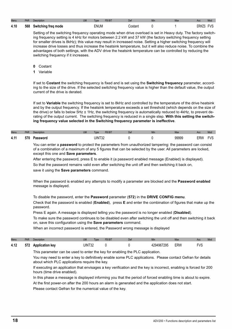
4.10 568 Switchingfreqmode ENUM Costant 0 1 ERWZS FVSSetting of the switching frequency operating mode when drive overload is set in Heavy duty. The factory switch-ing frequency setting is 4 kHz for motors between 2.2 kW and 37 kW (the factory switching frequency setting for smaller drives is 8kHz); this value may result in increased noise. Setting a higher switching frequency will increase drive losses and thus increase the heatsink temperature, but it will also reduce noise. To combine the advantages of both settings, with the ADV drive the heatsink temperature can be controlled by reducing the switching frequency if it increases.
0 Costant1 Variable
If set to Costant the switching frequency is fixed and is set using the Switchingfrequency parameter, accord-ing to the size of the drive. If the selected switching frequency value is higher than the default value, the output current of the drive is derated.
If set to Variable the switching frequency is set to 8kHz and controlled by the temperature of the drive heatsink and by the output frequency. If the heatsink temperature exceeds a set threshold (which depends on the size of the drive) or falls to below 5Hz ± 1Hz, the switching frequency is automatically reduced to 4kHz, to prevent de-rating of the output current. The switching frequency is reduced in a single step. Withthissettingtheswitch-ingfrequencyvalueselectedintheSwitchingfrequencyparameterisineffective.
Menu PAR Description UM Type FB BIT Def Min Max Acc Mod
4.11 570 Password UINT32 0 0 99999 ERW FVSYou can enter a password to protect the parameters from unauthorized tampering: the password can consist of a combination of a maximum of any 5 figures that can be selected by the user. All parameters are locked, except this one and Saveparameters.After entering the password, press E to enable it (a password enabled message (Enabled) is displayed).So that the password remains valid even after switching the unit off and then switching it back on,save it using the Saveparameters command.
When the password is enabled any attempts to modify a parameter are blocked and the Passwordenabled message is displayed.
To disable the password, enter the Password parameter (57�) in the DRIVECONFIG menu. Check that the password is enabled (Enabled), press E and enter the combination of figures that make up the password.Press E again. A message is displayed telling you the password is no longer enabled (Disabled).To make sure the password continues to be disabled even after switching the unit off and then switching it back on, save this configuration using the Saveparameters command.When an incorrect password is entered, the Password wrong message is displayed
Menu PAR Description UM Type FB BIT Def Min Max Acc Mod
4.12 572 Applicationkey UINT32 0 0 4294967295 ERW FVSThis parameter can be used to enter the key for enabling the PLC application.You may need to enter a key to definitively enable some PLC applications. Please contact Gefran for details about which PLC applications require the key.If executing an application that envisages a key verification and the key is incorrect, enabling is forced for 200 hours (time drive enabled). In this phase a message is displayed informing you that the period of forced enabling time is about to expire.At the first power-on after the 200 hours an alarm is generated and the application does not start.Please contact Gefran for the numerical value of the key.
ADV200 • Functions description and parameters list 19
Menu PAR Description UM Type FB BIT Def Min Max Acc Mod
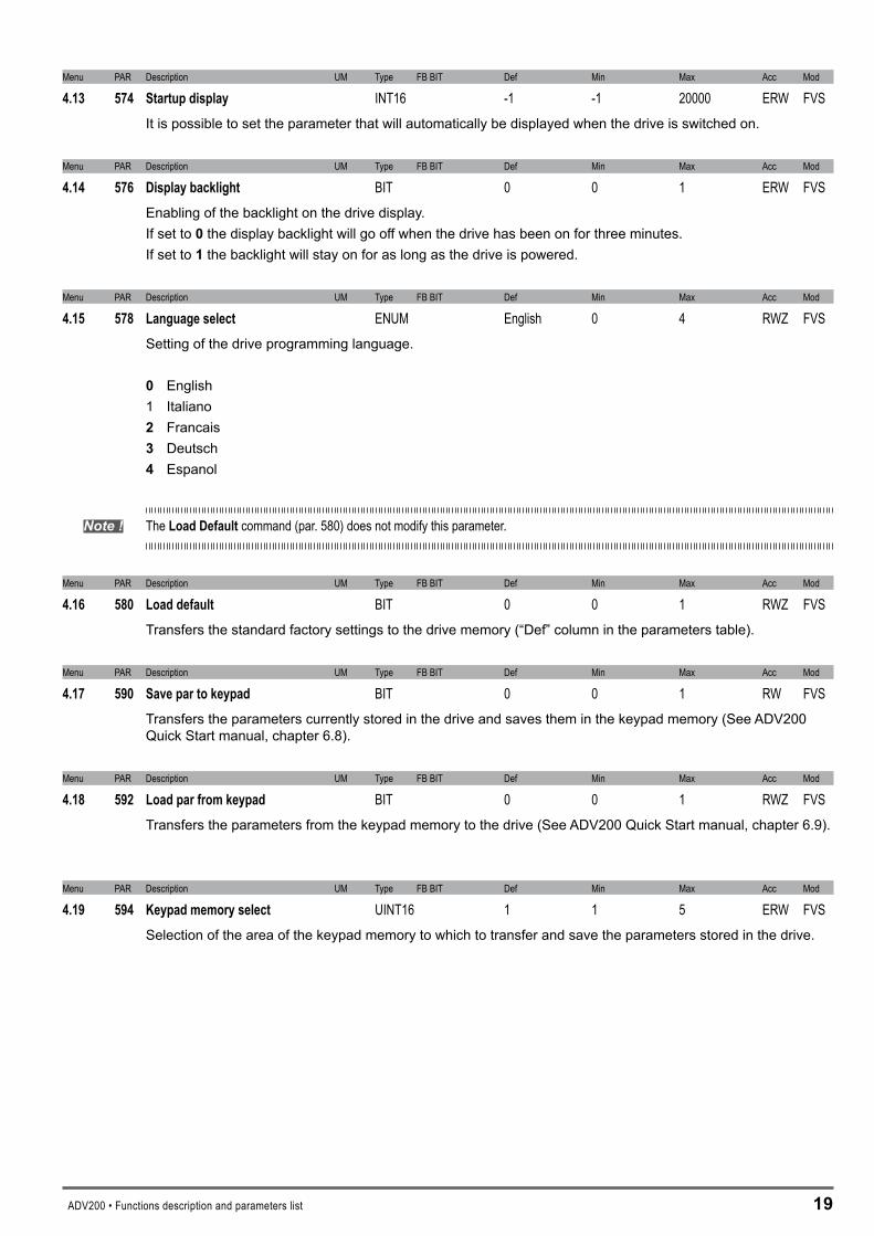
4.13 574 Startupdisplay INT16 -1 -1 20000 ERW FVSIt is possible to set the parameter that will automatically be displayed when the drive is switched on.
Menu PAR Description UM Type FB BIT Def Min Max Acc Mod
4.14 576 Displaybacklight BIT 0 0 1 ERW FVSEnabling of the backlight on the drive display. If set to 0 the display backlight will go off when the drive has been on for three minutes. If set to 1 the backlight will stay on for as long as the drive is powered.
Menu PAR Description UM Type FB BIT Def Min Max Acc Mod
4.15 578 Languageselect ENUM English 0 4 RWZ FVSSetting of the drive programming language.
0 English 1 Italiano � Francais � Deutsch 4 Espanol
Note ! The LoadDefaultcommand (par. 580) does not modify this parameter.
Menu PAR Description UM Type FB BIT Def Min Max Acc Mod
4.16 580 Loaddefault BIT 0 0 1 RWZ FVSTransfers the standard factory settings to the drive memory (“Def” column in the parameters table).
Menu PAR Description UM Type FB BIT Def Min Max Acc Mod
4.17 590 Savepartokeypad BIT 0 0 1 RW FVSTransfers the parameters currently stored in the drive and saves them in the keypad memory (See ADV200 Quick Start manual, chapter 6.8).
Menu PAR Description UM Type FB BIT Def Min Max Acc Mod
4.18 592 Loadparfromkeypad BIT 0 0 1 RWZ FVSTransfers the parameters from the keypad memory to the drive (See ADV200 Quick Start manual, chapter 6.9).
Menu PAR Description UM Type FB BIT Def Min Max Acc Mod
4.19 594 Keypadmemoryselect UINT16 1 1 5 ERW FVSSelection of the area of the keypad memory to which to transfer and save the parameters stored in the drive.
�0 ADV200 • Functions description and parameters list
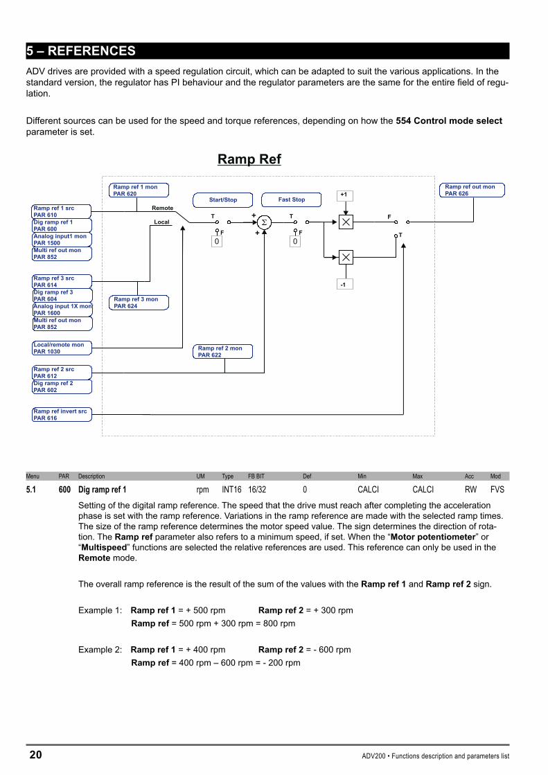
5–REFERENCESADV drives are provided with a speed regulation circuit, which can be adapted to suit the various applications. In the standard version, the regulator has PI behaviour and the regulator parameters are the same for the entire field of regu-lation.
Different sources can be used for the speed and torque references, depending on how the 554Controlmodeselect parameter is set.
T
F
T
F
F
T
Ramp Ref
Ramp ref 1 src610PAR
Ramp ref 2 src612PAR
+
+
+1
-1
Dig ramp ref 1600PAR
Dig ramp ref 2602PAR
Ramp ref 1 mon620PAR
Ramp ref 3 mon624PAR
Ramp ref invert src616PAR
Ramp ref out mon626PAR
Fast Stop
0
Start/Stop
0Analog input1 mon
1500PARMulti ref out monPAR 852
Ramp ref 3 srcPAR 614Dig ramp ref 3PAR 604Analog input 1X mon
1600PARMulti ref out monPAR 852
Ramp ref 2 mon622PAR
Local
Remote
Menu PAR Description UM Type FB BIT Def Min Max Acc Mod
5.1 600 Digrampref1 rpm INT16 16/32 0 CALCI CALCI RW FVSSetting of the digital ramp reference. The speed that the drive must reach after completing the acceleration phase is set with the ramp reference. Variations in the ramp reference are made with the selected ramp times. The size of the ramp reference determines the motor speed value. The sign determines the direction of rota-tion. The Rampref parameter also refers to a minimum speed, if set. When the “Motorpotentiometer” or “Multispeed” functions are selected the relative references are used. This reference can only be used in the Remote mode.
The overall ramp reference is the result of the sum of the values with the Rampref1 and Rampref� sign.
Example 1: Rampref1 = + 500 rpm Rampref�= + 300 rpm Rampref= 500 rpm + 300 rpm = 800 rpm
Example 2: Rampref1 = + 400 rpm Rampref� = - 600 rpm Rampref = 400 rpm – 600 rpm = - 200 rpm

ADV200 • Functions description and parameters list �1
Menu PAR Description UM Type FB BIT Def Min Max Acc Mod
5.2 602 Digrampref2 rpm INT16 16/32 0 CALCI CALCI ERW FVSSetting of the digital ramp reference. The speed that the drive must reach after completing the acceleration phase is set with the ramp reference. Variations in the ramp reference are made with the selected ramp times. The size of the ramp reference determines the motor speed value. The sign determines the direction of rota-tion. The Rampref parameter also refers to a minimum speed, if set. When the “Motorpotentiometer” or “Multispeed” functions are selected the relative references are used.
In Remote mode the overall ramp reference is the result of the sum of the values with the Ramp ref 1 and Ramp ref 2 sign.
Example 1: Rampref1 = + 500 rpm Rampref� = + 300 rpm Rampref = 500 rpm + 300 rpm = 800 rpm
Example 2: Rampref1 = + 400 rpm Rampref� = - 600 rpm Rampref= 400 rpm – 600 rpm = - 200 rpm
In Local mode the overall ramp reference is the result of the sum of the values with the Rampref� and Rampref� sign.
Example 1: Rampref� = + 500 rpm Rampref� = + 300 rpm Rampref = 500 rpm + 300 rpm = 800 rpm
Example 2: Rampref� = + 400 rpm Rampref� = - 600 rpm Rampref = 400 rpm – 600 rpm = - 200 rpm
Menu PAR Description UM Type FB BIT Def Min Max Acc Mod
5.3 604 Digrampref3 rpm INT16 16/32 0 CALCI CALCI ERW FVSSetting of the digital ramp reference. The speed that the drive must reach after completing the acceleration phase is set with the ramp reference. Variations in the ramp reference are made with the selected ramp times. The size of the ramp reference determines the motor speed value. The sign determines the direction of rota-tion. The Rampref parameter also refers to a minimum speed, if set. When the “Motorpotentiometer” or “Multispeed” functions are selected the relative references are used. This reference can only be used in the Local mode.
The overall ramp reference is the result of the sum of the values with the Rampref� and Rampref� sign.
Example 1: Rampref� = + 500 rpm Rampref� = + 300 rpm Rampref = 500 rpm + 300 rpm = 800 rpm
Example 2: Rampref� = + 400 rpm Rampref� = - 600 rpm Rampref = 400 rpm – 600 rpm = - 200 rpm
Menu PAR Description UM Type FB BIT Def Min Max Acc Mod
5.4 610 Rampref1src LINK 16/32 852 0 16384 RW FVS5.5 612 Rampref2src LINK 16/32 602 0 16384 ERW FVS5.6 614 Rampref3src LINK 16/32 894 0 16384 ERW FVS
Selection of the origin (source) of the reference signals on the input of the ramp function block, that defines the main drive speed. The ramp reference values can be selected from among those listed in the “L_MLTREF” selection list.When assigning the reference via terminals, signals with ±10V, 0 ...10V, 0... 20 mA and 4 ... 20 mA can be used.
�� ADV200 • Functions description and parameters list
Menu PAR Description UM Type FB BIT Def Min Max Acc Mod
5.7 616 Ramprefinvertsrc LINK 16 1050 0 16384 ERW FVSSelection of the origin (source) of the signal that inverts the ramp reference output from the “Ramp ref” block. The signal that can be used for this function can be selected from among those listed in the “L_DIGSEL�” selection list.
Menu PAR Description UM Type FB BIT Def Min Max Acc Mod
5.8 620 Rampref1mon rpm INT16 0 0 0 R FVS5.9 622 Rampref2mon rpm INT16 0 0 0 ER FVS5.10 624 Rampref3mon rpm INT16 0 0 0 ER FVS
The value of the relative ramp reference on the output of the relative function block is displayed.

ADV200 • Functions description and parameters list ��
Reference Skip
Reference skip set630PAR
Reference skip band632PAR Reference in
Reference out
Ramp setpoint628PAR
Ramp ref out mon626PAR
In a system comprising a drive and motor, vibrations may be generated at certain frequencies, due to mechani-cal resonance. This phenomenon can be limited by entering a prohibited speed at which the drive cannot oper-ate.
Menu PAR Description UM Type FB BIT Def Min Max Acc Mod
5.11 630 Referenceskipset rpm INT16 0 0 CALCI ERW FVSSetting of the prohibited speed threshold at which the drive cannot operate.
Menu PAR Description UM Type FB BIT Def Min Max Acc Mod
5.12 632 Referenceskipband rpm INT16 0 0 CALCI ERW FVSSetting of the prohibited bandwidth.
Par. 630
Reference out
Reference in
Par6
32
Par. 630
Par. 632 Par. 632
Example: A) Increase in the reference by values of less than Par. 630
Par. 630 = 300 rpm (prohibited speed threshold)Par. 632 = 10 rpm (thus prohibited band: 290rpm.310rpm)Set speed reference = 295 rpmHzOutput speed = 290 rpmSet speed reference = 305 rpmOutput speed = 290 rpm
�4 ADV200 • Functions description and parameters list
B) Decrease in the reference by values above Par. 630
Par.630 = 300 rpm (prohibited speed threshold)Par.632 = 10 rpm (thus tolerance band: 290 rpm…310 rpm)
Set speed reference = 305 rpmOutput frequency = 310 rpm Set speed reference = 295 rpm Output frequency = 310 rpm
The user can thus set any reference value, but if the set value is within the prohibited range, the drive automati-cally maintains the speed outside the limits defined by the tolerance band.During ramp phases the prohibited speed is passed freely and there are no points of discontinuity in the gen-eration of the output frequency.

ADV200 • Functions description and parameters list �5
T
+
+
+
+
+1
-1
F
T0
F
0
FFrom Ramp output
From Jog output
Speed Reference
Speed ref 1 monPAR 660
Speed ref 2 monPAR 662
Speed ref bottom limPAR 672
Speed ref top limPAR 670
Speed setpointPAR 664
Speed ratio monPAR 3004
Start/Stop
Speed ref 1 srcPAR 650
Dig speed ratioPAR 3000
Dig speed ref 1PAR 640
Dig speed ref 2PAR 642
Speed ratio srcPAR 3002
Speed ref invert srcPAR 654
Control mode selectPAR 556
Fast Stop
Speed ref 2 srcPAR 652
Speed ratio outPAR 3004
The speed reference supplies the desired speed to the drive, which directly follows the reference pattern. This only happens when the available torque is sufficient. In this case the drive functions at its current limit, until reaching the set speed. The speed reference value determines the motor speed value. The sign determines the direction of rotation.
Menu PAR Description UM Type FB BIT Def Min Max Acc Mod
5.13 640 Digspeedref1 rpm INT16 16/32 0 CALCI CALCI ERW FVS5.14 642 Digspeedref2 rpm INT16 16/32 0 CALCI CALCI ERW FVS
Setting of the digital speed references. The overall speed reference is the result of the sum of the values with the respective signs, of Digspeedref1 and Digspeedref�. The digital speed references are linked to the ramp circuit output.
The overall speed reference is the result of the sum of the values, with sign, of Speedref1 and Speedref�.
Example 1: Speedref1 = + 500 rpm Speedref� = + 300 rpm Speedref = 500 rpm + 300 rpm = 800 rpm
Example 2: Speedref1 = + 400 rpm Speedref� = - 600 rpm Speedref= 400 rpm – 600 rpm = - 200 rpm
Menu PAR Description UM Type FB BIT Def Min Max Acc Mod
5.15 650 Speedref1src LINK 16/32 640 0 16384 ERW FVS5.16 652 Speedref2src LINK 16/32 642 0 16384 ERW FVS
Selection of the origin (source) of the drive speed reference signals. The values that can be used as speed references can be selected from those listed in the “L_MLTREF” selection list. When assigning the reference via terminals, signals with ±10V, 0 ...10V, 0... 20 mA and 4 ... 20 mA can be used.
Menu PAR Description UM Type FB BIT Def Min Max Acc Mod
5.17 654 Speedrefinvertsrc LINK 16 6000 0 16384 ERWZ FVSSelection of the origin (source) of the signal that inverts the speed reference output from the regulator. The ter-minal that can be used for this function can be selected from among those listed in the “L_DIGSEL�” selection list.
Menu PAR Description UM Type FB BIT Def Min Max Acc Mod
5.18 660 Speedref1mon rpm INT16 0 0 0 ER FVS5.19 662 Speedref2mon rpm INT16 0 0 0 ER FVS
The value of the relative speed reference is displayed.

�6 ADV200 • Functions description and parameters list
Menu PAR Description UM Type FB BIT Def Min Max Acc Mod
5.20 670 Speedreftoplim rpm INT16 CALCI 0 CALCI RWZ FVSSetting of the upper speed reference limit. If the speed reference exceeds the limits, the motor speed remains at the set limit value in any case. Speed limits cannot be more than 200% of the value set in the Fullscalespeed parameter (REFENCES menu par. 680).
Menu PAR Description UM Type FB BIT Def Min Max Acc Mod
5.21 672 Speedrefbottomlim rpm INT16 CALCI CALCI 0 RWZ FVSSetting of the lower speed reference limit. If the speed reference exceeds the limits, the motor speed remains at the set limit value in any case. Speed limits cannot be more than 200% of the value set in the Fullscalespeed parameter (REFERENCES menu par. 680).
Menu PAR Description UM Type FB BIT Def Min Max Acc Mod
5.22 680 Fullscalespeed rpm INT16 CALCI 50 32000 RWZ FVSSetting of the reference value for all speed percentage data (References, Speed adaptives ...) corresponding to 100 % of the actual speed. This parameter can only be changed with the inverter blocked (Enable drive = Disabled). The recommended setting for the value of this parameter is the motor rated speed. If altered, the self-tuning procedure should be repeated.Fullscalespeed does not define the maximum possible speed. In any case, the maximumspeed percentage value is ± 200 % of the Fullscalespeed value.

ADV200 • Functions description and parameters list �7
6–RAMPS
0
Linear
Shape
0
ToSpeed setpoint
input
F
T
Bypass
Ramp function
CTRL
0
off
F
T
Ramp
Multi Ramp
Ramp setpoint628PAR
Ramp in zero src750PAR
Ramp out zero src752PAR
Ramp out zero srcPAR 752
Ramp freeze src754PAR
Acceleration time 0700PAR
Deceleration time 0702PAR
Accel jerk time 0730PAR
Decel jerk time 0PAR 732
Acceleration time 3712PAR
Deceleration time 3714PAR
Accel jerk time 3742PAR
Decel jerk time 3744PAR
Acceleration time 2708PAR
Deceleration time 2710PAR
Accel jerk time 2738PAR
Decel jerk time 2740PAR
Multi ramp sel 0 src722PAR
Multi ramp sel 1 src724PAR
Multi ramp sel monIPA726
Ramp type720PAR
Mlt ramp sel
Acceleration time 1704PAR
Deceleration time 1706PAR
Accel jerk time 1734PAR
Decel jerk time 1PAR 736
The ramp (reference integrator) determines the acceleration and deceleration times of the drive. Times can be set independently.
The ramp times of Fast stop command are set on Acceleration time 3 and Deceleration time 3. The command can be enabled from the terminal strip..
The ramp can be linear or S-shaped, as preferred.
The references can be set in different ways:- with the Ramp ref 1 and / or Ramp ref 2 references- with the Multi speed function- with the Motor potentiometer function- with the Jog function
The ramp generator can be used in the “stand alone” mode. When disabled (Ramptype=Off), the “Enable drive, Start/Stop and Fast stop” commands do not affect the ramp generator. In this condition the ramp generator can be used separately.
�� ADV200 • Functions description and parameters list
Menu PAR Description UM Type FB BIT Def Min Max Acc Mod
6.1 700 Accelerationtime0 s FLOAT 10.00 0.01 1000.00 RW FVS6.2 702 Decelerationtime0 s FLOAT 10.00 0.01 1000.00 RW FVS6.3 704 Accelerationtime1 s FLOAT 10.00 0.01 1000.00 ERW FVS6.4 706 Decelerationtime1 s FLOAT 10.00 0.01 1000.00 ERW FVS6.5 708 Accelerationtime2 s FLOAT 10.00 0.01 1000.00 ERW FVS6.6 710 Decelerationtime2 s FLOAT 10.00 0.01 1000.00 ERW FVS6.7 712 Accelerationtime3 s FLOAT 10.00 0.01 1000.00 ERW FVS6.8 714 Decelerationtime3 s FLOAT 10.00 0.01 1000.00 ERW FVS
The acceleration and deceleration ramp times are used to avoid sudden changes in the drive output frequency, which could cause mechanical shocks, excessive current on the motor and excessive DC-bus voltage values. The acceleration times (6.1,6.�,6.5,6.7) are expressed as the time necessary to bring the frequency from zero to the maximum value set in the Fullscalespeed(5.��). On the other hand, the deceleration times (6.�,6.4,6.6,6.�) are expressed as the time necessary to bring the frequency from the maximum value set in the Fullscalespeed(5.��) parameter to zero. Each of the 4 available ramp selections can be selected using one or two digital inputs programmed asMultirampsel.
Menu PAR Description UM Type FB BIT Def Min Max Acc Mod
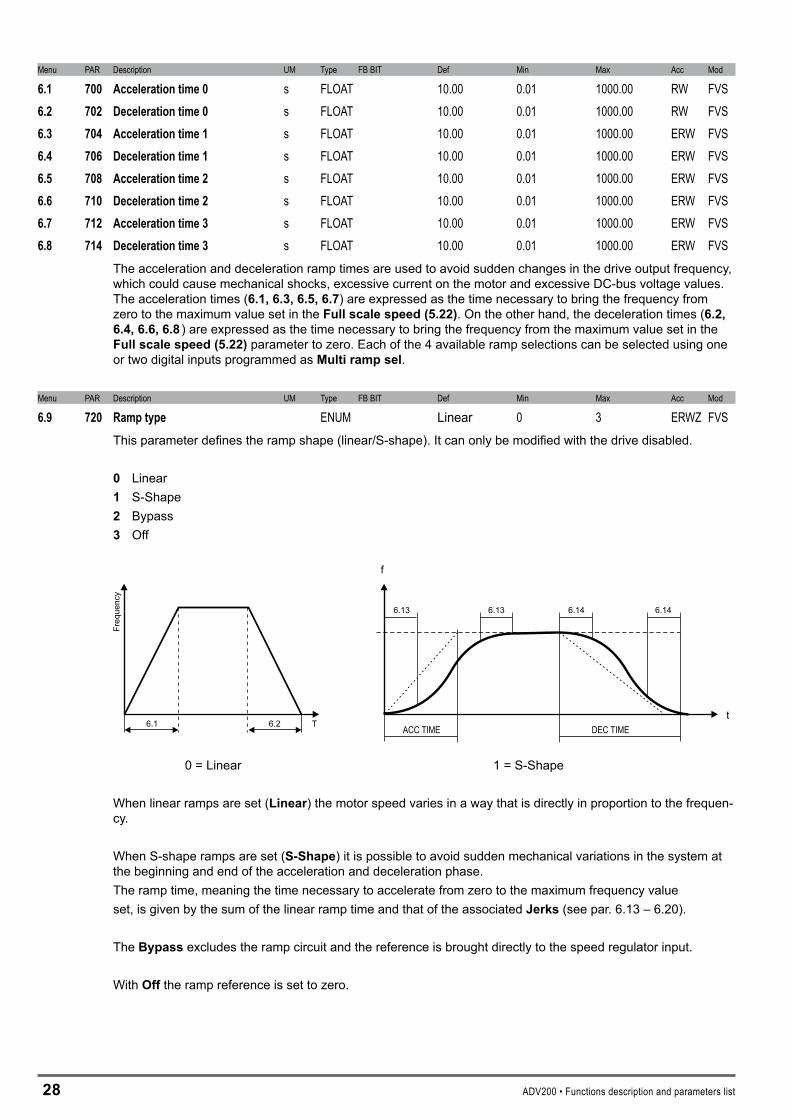
6.9 720 Ramptype ENUM Linear 0 3 ERWZ FVSThis parameter defines the ramp shape (linear/S-shape). It can only be modified with the drive disabled.
0 Linear 1 S-Shape � Bypass � Off
f
tACC TIME DEC TIME6.1 6.2
Freq
uenc
y
T
6.13 6.13 6.14 6.14
0 = Linear 1 = S-Shape
When linear ramps are set (Linear) the motor speed varies in a way that is directly in proportion to the frequen-cy.
When S-shape ramps are set (S-Shape) it is possible to avoid sudden mechanical variations in the system at the beginning and end of the acceleration and deceleration phase. The ramp time, meaning the time necessary to accelerate from zero to the maximum frequency valueset, is given by the sum of the linear ramp time and that of the associated Jerks (see par. 6.13 – 6.20).
The Bypass excludes the ramp circuit and the reference is brought directly to the speed regulator input.
With Off the ramp reference is set to zero.

ADV200 • Functions description and parameters list �9
Menu PAR Description UM Type FB BIT Def Min Max Acc Mod
6.10 722 Multirampsel0 LINK 6000 0 16384 ERWZ FVS6.11 724 Multirampsel1 LINK 6000 0 16384 ERWZ FVS
1 or 2 digital inputs can be used to select one of the 4 available sets of ramps. The origin (source) of the command to enable the ramp selection function can be selected from the “L_DIG-SEL�” selection list.
The following table describes the ramp selection procedure:
Enabledramptime Multirampsel0 Multirampsel1
Acceleration time 0Deceleration time 0 0 0
Acceleration time 1Deceleration time 1 1 0
Acceleration time 2Deceleration time 2 0 1
Acceleration time 3Deceleration time 3 1 1
Menu PAR Description UM Type FB BIT Def Min Max Acc Mod
6.12 726 Multirampselmon UINT16 0 0 3 ER FVSThe set of acceleration/deceleration ramps selected using the digital inputs is displayed.
Menu PAR Description UM Type FB BIT Def Min Max Acc Mod
6.13 730 Acceljerktime0 s FLOAT 1.0 0.02 10.0 ERW FVS6.14 732 Deceljerktime0 s FLOAT 1.0 0.02 10.0 ERW FVS6.15 734 Acceljerktime1 s FLOAT 1.0 0.02 10.0 ERW FVS6.16 736 Deceljerktime1 s FLOAT 1.0 0.02 10.0 ERW FVS6.17 738 Acceljerktime2 s FLOAT 1.0 0.02 10.0 ERW FVS6.18 740 Deceljerktime2 s FLOAT 1.0 0.02 10.0 ERW FVS6.19 742 Acceljerktime3 s FLOAT 1.0 0.02 10.0 ERW FVS6.20 744 Deceljerktime3 s FLOAT 1.0 0.02 10.0 ERW FVS
Jerks are variations of acceleration in time. They are used when there is a need to dampen the beginning and end of the ramp. The Jerk value is added, regardless of the variation in speed, to the linear ramp time.
f
tACC TIME DEC TIME
6.13 6.13 6.14 6.14

�0 ADV200 • Functions description and parameters list
Menu PAR Description UM Type FB BIT Def Min Max Acc Mod
6.21 750 Rampinzerosrc LINK 16 6000 0 16384 ERW FVSSelection of the origin (source) of the signal that blocks the ramp input and moves the reference to zero. If the ramp input is enabled, the Rampref parameter corresponds to the set reference. If the ramp input is blocked, the drive slows down with the set deceleration time until reaching zero speed. The terminal to be associated with this function can be selected from the “L_DIGSEL�” selection list.
Menu PAR Description UM Type FB BIT Def Min Max Acc Mod
6.22 752 Rampoutzerosrc LINK 16 6000 0 16384 ERW FVSSelection of the origin (source) of the signal that brings the ramp to 0 (Rampref1/Rampref�=0). When the ramp output is set to zero using Rampoutzero, the drive brakes with the maximum available torque; in this case the ramp is disabled. The terminal to be associated with this function can be selected from the “L_DIG-SEL�” selection list.
Menu PAR Description UM Type FB BIT Def Min Max Acc Mod
6.23 754 Rampfreezesrc LINK 16 6000 0 16384 ERW FVSSelection of the origin (source) of the signal that temporarily freezes the ramp output value, regardless of any changes in the input reference. The terminal to be associated with this function can be selected from the “L_DIGSEL�” selection list.
Ramp freeze
Ramp Output(Motor speed)
ADV200 • Functions description and parameters list �1
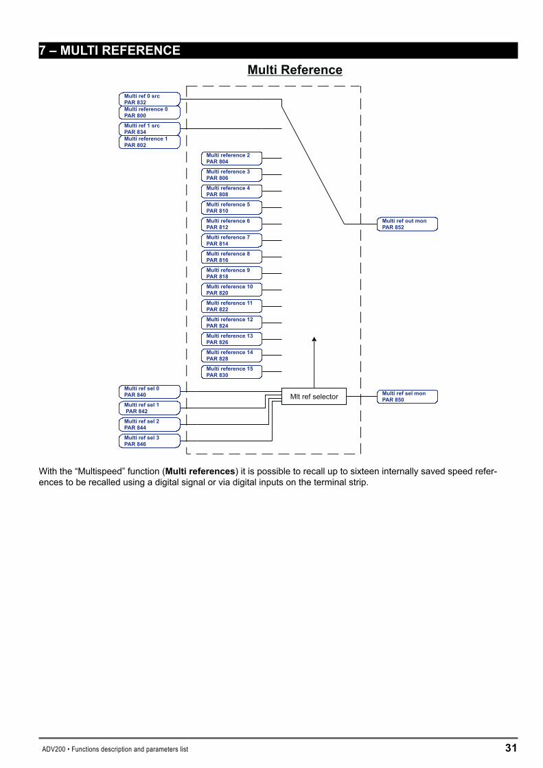
7–MULTIREFERENCEMulti Reference
Multi ref 0 srcPAR 832
Multi ref 1 srcPAR 834
Multi reference 2PAR 804
Multi reference 3PAR 806
Multi reference 4PAR 808
Multi reference 5PAR 810
Multi reference 6PAR 812
Multi reference 7PAR 814
Multi reference 8PAR 816
Multi reference 9PAR 818
Multi reference 10PAR 820
Multi reference 11PAR 822
Multi reference 12PAR 824
Multi reference 13PAR 826
Multi reference 14PAR 828
Multi reference 15PAR 830
Multi ref out monPAR 852
Multi ref sel 0PAR 840
Multi ref sel 1PAR 842
Multi ref sel 2PAR 844
Multi ref sel 3PAR 846
Mlt ref selector Multi ref sel monPAR 850
Multi reference 0PAR 800
Multi reference 1PAR 802
With the “Multispeed” function (Multireferences) it is possible to recall up to sixteen internally saved speed refer-ences to be recalled using a digital signal or via digital inputs on the terminal strip.
�� ADV200 • Functions description and parameters list
Menu PAR Description UM Type FB BIT Def Min Max Acc Mod
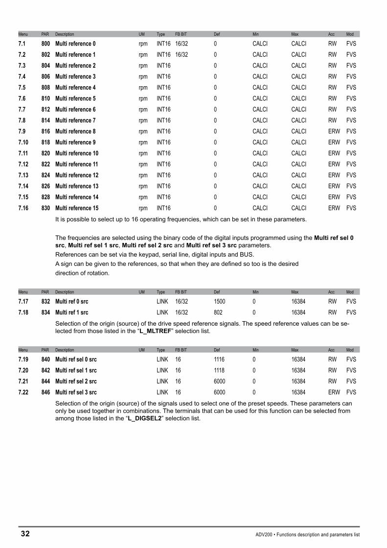
7.1 800 Multireference0 rpm INT16 16/32 0 CALCI CALCI RW FVS7.2 802 Multireference1 rpm INT16 16/32 0 CALCI CALCI RW FVS7.3 804 Multireference2 rpm INT16 0 CALCI CALCI RW FVS7.4 806 Multireference3 rpm INT16 0 CALCI CALCI RW FVS7.5 808 Multireference4 rpm INT16 0 CALCI CALCI RW FVS7.6 810 Multireference5 rpm INT16 0 CALCI CALCI RW FVS7.7 812 Multireference6 rpm INT16 0 CALCI CALCI RW FVS7.8 814 Multireference7 rpm INT16 0 CALCI CALCI RW FVS7.9 816 Multireference8 rpm INT16 0 CALCI CALCI ERW FVS7.10 818 Multireference9 rpm INT16 0 CALCI CALCI ERW FVS7.11 820 Multireference10 rpm INT16 0 CALCI CALCI ERW FVS7.12 822 Multireference11 rpm INT16 0 CALCI CALCI ERW FVS7.13 824 Multireference12 rpm INT16 0 CALCI CALCI ERW FVS7.14 826 Multireference13 rpm INT16 0 CALCI CALCI ERW FVS7.15 828 Multireference14 rpm INT16 0 CALCI CALCI ERW FVS7.16 830 Multireference15 rpm INT16 0 CALCI CALCI ERW FVS
It is possible to select up to 16 operating frequencies, which can be set in these parameters.
The frequencies are selected using the binary code of the digital inputs programmed using the Multirefsel0src, Multirefsel1src, Multirefsel�src and Multirefsel�src parameters.References can be set via the keypad, serial line, digital inputs and BUS.A sign can be given to the references, so that when they are defined so too is the desireddirection of rotation.
Menu PAR Description UM Type FB BIT Def Min Max Acc Mod
7.17 832 Multiref0src LINK 16/32 1500 0 16384 RW FVS7.18 834 Multiref1src LINK 16/32 802 0 16384 RW FVS
Selection of the origin (source) of the drive speed reference signals. The speed reference values can be se-lected from those listed in the “L_MLTREF” selection list.
Menu PAR Description UM Type FB BIT Def Min Max Acc Mod
7.19 840 Multirefsel0src LINK 16 1116 0 16384 RW FVS7.20 842 Multirefsel1src LINK 16 1118 0 16384 RW FVS7.21 844 Multirefsel2src LINK 16 6000 0 16384 RW FVS7.22 846 Multirefsel3src LINK 16 6000 0 16384 ERW FVS
Selection of the origin (source) of the signals used to select one of the preset speeds. These parameters can only be used together in combinations. The terminals that can be used for this function can be selected from among those listed in the “L_DIGSEL�” selection list.
ADV200 • Functions description and parameters list ��
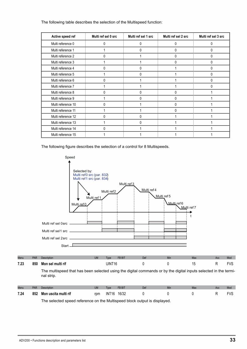
The following table describes the selection of the Multispeed function:
Activespeedref Multirefsel0src Multirefsel1src Multirefsel2src Multirefsel3src
Multi reference 0 0 0 0 0Multi reference 1 1 0 0 0Multi reference 2 0 1 0 0Multi reference 3 1 1 0 0Multi reference 4 0 0 1 0Multi reference 5 1 0 1 0Multi reference 6 0 1 1 0Multi reference 7 1 1 1 0Multi reference 8 0 0 0 1Multi reference 9 1 0 0 1Multi reference 10 0 1 0 1Multi reference 11 1 1 0 1Multi reference 12 0 0 1 1Multi reference 13 1 0 1 1Multi reference 14 0 1 1 1Multi reference 15 1 1 1 1
The following figure describes the selection of a control for 8 Multispeeds.
Multi ref sel 0src
Multi ref sel1 src
Multi ref sel 2src
Start
Speed
t
Multi ref 0
Multi ref 1
Multi ref2
Multi ref 3Multi ref 4
Multi ref 5
Multi ref 6Multi ref 7
Selected by:Multi ref0 src (par. 832)Multi ref1 src (par. 834)
Menu PAR Description UM Type FB BIT Def Min Max Acc Mod
7.23 850 Monselmultirif UINT16 0 0 15 R FVSThe multispeed that has been selected using the digital commands or by the digital inputs selected in the termi-nal strip.
Menu PAR Description UM Type FB BIT Def Min Max Acc Mod
7.24 852 Monuscitamultirif rpm INT16 16/32 0 0 0 R FVSThe selected speed reference on the Multispeed block output is displayed.

�4 ADV200 • Functions description and parameters list
�–MOTORPOTENTIOMETER
Mpot
MPOTCTRL
Mpot invert srcPAR 888
Mpot preset srcPAR 890
Mpot output mon890PAR
Mpot init cfg880PAR
Mpot preset cfg882PAR
Mpot mode892PAR
Mpot bottom lim878PAR
Mpot top lim876PAR
Mpot accelerationPAR 872
Mpot deceleration874PAR
DownFast stop
Start/stop
Preset ctrl
+1
-1
Acc
Dec
Controlmode select556PAR
Mpot up src884PAR
Mpot down src886PAR
Mpot setpoint870PAR
The Motor potentiometer function allows the speed reference of the drive to be changed by pressing buttons with which the UP and DOWN commands are associated.The UP and DOWN commands can be sent from the keypad, by digital inputs, the serial line or fieldbus.To send the UP and DOWN commands from the keypad, enter the MPotsetpointparameter modify mode and press the UP and DOWN keys.The UP and DOWN commands increase or decrease the speed of the motor for as long as they are present. The simultaneous presence of both commands will not produce any change (see time chart).The speed changes according to the set ramp times and within the set lower and upper limits.The value of the Motor potentiometer function output at drive power-on can be configured.The preset command can be used to force a preset value for the input and output of the Motor potentiometer function.The invert command can be used to force an inversion of the reference sign of the Motor potentiometer function.In the default condition, the speed reference produced by the Motor potentiometer function is connected in input to the Ramp function. For direct control of the motor speed, the Acceleration time and Deceleration time parameters in the RAMP menu should be set = 0.
Note ! The Motor potentiometer function produces a speed reference. Therefore a RUN command must always be sent to start motor rotation.
Mpot top lim
Mpot bottom lim
Up
Down
Mpot output mon

ADV200 • Functions description and parameters list �5
Menu PAR Description UM Type FB BIT Def Min Max Acc Mod
8.1 870 Mpotsetpoint rpm INT16 16/32 0 CALCI CALCI R FVSThe speed reference value of the Motor potentiometer function is displayed.Enter this parameter to send the UP and DOWN commands from the keypad.
Menu PAR Description UM Type FB BIT Def Min Max Acc Mod
8.2 872 Mpotacceleration s FLOAT 5.0 0.01 1000.00 RW FVS8.3 874 Mpotdeceleration s FLOAT 5.0 0.01 1000.00 RW FVS
Setting of the acceleration/deceleration ramp times (in seconds) used with the Motor potentiometer function.
Menu PAR Description UM Type FB BIT Def Min Max Acc Mod
8.4 876 Mpottoplim rpm INT16 1500 CALCI CALCI ERW FVSSetting of the top limit for the speed reference output from the motor potentiometer.
Menu PAR Description UM Type FB BIT Def Min Max Acc Mod
8.5 878 Mpotbottomlimit rpm INT16 0 CALCI CALCI ERW FVSSetting of the bottom limit for the speed reference output from the motor potentiometer.
Menu PAR Description UM Type FB BIT Def Min Max Acc Mod
8.6 880 Mpotinitcfg ENUM Zero 0 3 ERW FVSUse this parameter to configure the output value of the Motor potentiometer at drive start-up. 0 Last power off 1 Zero � Lower Limit � Upper Limit
When set to Lastpoweroff, the motor potentiometer output starts from the last frequency that was set before the drive was switched off.
When set to Zero the motor potentiometer output starts from a value of 0.
When set to Lowerlimit the output of the motor potentiometer starts from the value of the lower limit set in the Mpotbottomlimit parameter. When set to Upperlimit the output of the motor potentiometer starts from the value of the upper limit set in the Mpottoplimit parameter.

�6 ADV200 • Functions description and parameters list
Menu PAR Description UM Type FB BIT Def Min Max Acc Mod
8.7 882 Mpotpresetcfg ENUM None 0 11 ERW FVSThis parameter can be used to configure the preset of the Motor potentiometer function, i.e. to configure the value at which the Motor potentiometer input and output are set when the Preset command is enabled.The Preset command has priority over the Up command and the Down command.The Up and Down commands are enabled again when the Preset command is disabled.
0 None1 Input = 0� Input = low lim � Input & ref = 04 Input & ref = low lim5 Output = 0 6 Output = low lim 7 Output & ref = 0 � Output & ref = low lim9 Input = upp lim10 Input & ref = upp lim11 Freeze input
When set to None, no setting is executed.
Input=0 sets input = 0 i.e. a temporary reference setting is performed and the previous reference value is maintained. The output of the Motor potentiometer function varies with the set ramp times. The previous refer-ence value is restored when the preset command is removed.
Input=lowlim sets Inp = low lim i.e. a temporary reference setting is performed and the previous reference value is maintained. The output of the Motor potentiometer function varies with the set ramp times. The previ-ous reference value is restored when the preset command is removed.
Input&ref=0 sets Inp = 0 and Ref = 0 i.e. a definitive reference setting is performed. The output of the Motor potentiometer function varies with the set ramp times.
Input&ref=lowlim sets Inp = low lim and Ref = low lim i.e. a definitive reference setting is performed. The output of the Motor potentiometer function varies with the set ramp times.
Output=0 sets Out = 0 i.e. a temporary output setting for the Motor potentiometer function is performed. The previous reference value is maintained. If the preset command is enabled, the output of the Motor potentiom-eter function continues to be = 0, if the preset command is not enabled the output of the Motor potentiometer function varies with the set ramp times.
Output=lowlim sets Out = low lim i.e. a temporary setting for the output of the Motor potentiometer function is performed. Il precedente valore di riferimento viene mantenuto .The previous reference value is maintained. If the preset command is enabled, the output of the Motor potentiometer function continues to be = low lim, if the preset command is not enabled the output of the Motor potentiometer function varies with the set ramp times.
Output&ref=0 sets Out = 0 i.e. a definitive setting for the output of the Motor potentiometer function is per-formed.
Output&ref=low lim sets Out = low lim i.e. a definitive setting for the output of the Motor potentiometer func-tion is performed.
Input=upplim sets Inp = upp lim i.e. a temporary setting for the reference is performed and the previous ref-erence value is maintained. The output of the Motor potentiometer function varies with the set ramp times. The previous reference value is restored when the preset command is removed.
Input&ref=upplim sets Inp = upp lim and Ref = upp lim i.e. a definitive reference setting is performed. The output of the Motor potentiometer function varies with the set ramp times.
When Freezeinput is set, the Up and Down commands are temporarily disabled.
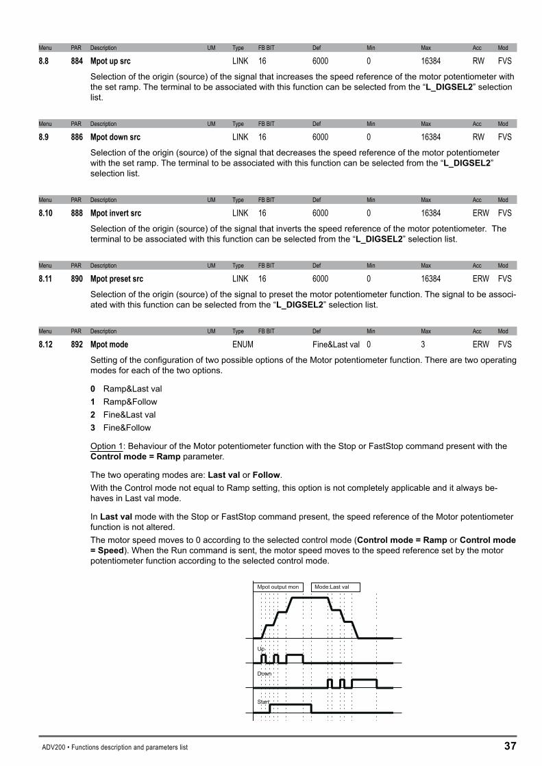
ADV200 • Functions description and parameters list �7
Menu PAR Description UM Type FB BIT Def Min Max Acc Mod
8.8 884 Mpotupsrc LINK 16 6000 0 16384 RW FVSSelection of the origin (source) of the signal that increases the speed reference of the motor potentiometer with the set ramp. The terminal to be associated with this function can be selected from the “L_DIGSEL�” selection list.
Menu PAR Description UM Type FB BIT Def Min Max Acc Mod
8.9 886 Mpotdownsrc LINK 16 6000 0 16384 RW FVSSelection of the origin (source) of the signal that decreases the speed reference of the motor potentiometer with the set ramp. The terminal to be associated with this function can be selected from the “L_DIGSEL�” selection list.
Menu PAR Description UM Type FB BIT Def Min Max Acc Mod
8.10 888 Mpotinvertsrc LINK 16 6000 0 16384 ERW FVSSelection of the origin (source) of the signal that inverts the speed reference of the motor potentiometer. The terminal to be associated with this function can be selected from the “L_DIGSEL�” selection list.
Menu PAR Description UM Type FB BIT Def Min Max Acc Mod
8.11 890 Mpotpresetsrc LINK 16 6000 0 16384 ERW FVSSelection of the origin (source) of the signal to preset the motor potentiometer function. The signal to be associ-ated with this function can be selected from the “L_DIGSEL�” selection list.
Menu PAR Description UM Type FB BIT Def Min Max Acc Mod
8.12 892 Mpotmode ENUM Fine&Last val 0 3 ERW FVSSetting of the configuration of two possible options of the Motor potentiometer function. There are two operating modes for each of the two options.
0 Ramp&Last val 1 Ramp&Follow � Fine&Last val � Fine&Follow
Option 1: Behaviour of the Motor potentiometer function with the Stop or FastStop command present with the Controlmode=Ramp parameter.
The two operating modes are: Lastval or Follow.With the Control mode not equal to Ramp setting, this option is not completely applicable and it always be-haves in Last val mode.
In Lastval mode with the Stop or FastStop command present, the speed reference of the Motor potentiometer function is not altered.The motor speed moves to 0 according to the selected control mode (Controlmode=Ramp or Controlmode=Speed). When the Run command is sent, the motor speed moves to the speed reference set by the motor potentiometer function according to the selected control mode.
Up
Down
Mpot output mon Mode:Last val
Start

�� ADV200 • Functions description and parameters list
In Follow mode with the Stop or FastStop command present, the Down command is simulated, i.e. the output of the Motor potentiometer function moves to 0 with the set ramp time.If the Run command is sent when the 0 speed has been reached, it is maintained until the Up command is sent. If the Run command is sent before the motor reaches the 0 speed, the speed at that moment is taken as the new reference.
Up
Down
Monitor uscita Mpot Mod.:Seguente
Start
Option 2: Ramp behaviour
The two operating modes are: Ramp or FineIn Ramp mode, each time the Up or Down commands are enabled, the output of the Motor potentiometer func-tion increases or decreases with the set ramp. When the Up or Down command is removed, the last value that was reached is maintained.
Up
Down
Monitor uscita Mpot Mod.:Rampa
In Fine mode, each time the Up or Down commands are enabled, the output of the Motor potentiometer func-tion increases or decreases by 1 rpm. If the command persists for less than 1 second, no other changes are made on the output.If the command persists for more than 1 second, the output increases or decreases with the set ramp. The vari-ation with the set ramp is performed gradually (1 second). When the Up or Down command is removed the last value that was reached is maintained.
Up
Down
Monitor uscita Mpot
1s 1s
1rpm
1rpm
Mod.:Precis

ADV200 • Functions description and parameters list �9
Mpotmode RampbehaviourBehaviour of the Motor potentiometer function with
the Stop or FastStop command present with the Controlmode=Ramp parameter.
0 Ramp Last val1 Ramp Follow2 Fine Last val3 Fine Follow
Menu PAR Description UM Type FB BIT Def Min Max Acc Mod
8.13 894 Mpotoutputmon rpm INT16 16/32 0 0 0 ER FVSThe value of the output of the motor potentiometer function is displayed.
Two examples of application of the motor potentiometer function are shown below.
Manualspeedcontrolwithcommandsentfromcontroldesk.
M
ADV
Mpot up
Mpot down
UP DOWN
Speed
Command console
The Up and Down keys are used to adjust the speed of a motor.For fine-tuning of the speed reference value the recommended settings are MpotMode=Fine&Follow or Fine&LastVal. Each time they are pressed for 1 second, the speed increases by 1 rpm. For an immediate ef-fect on motor speed, the Acceleration time and Deceleration time parameters should be set to short times.

40 ADV200 • Functions description and parameters list
Automaticspeedcontrolforrudimentarydancercontrol.
M
ADV1
M
ADV2
0V
10V
Center
Bottom
Top24V
24V
Mpot up
Mpot down
Ramp ref
The limit switches at the ends of dancer travel ranges are connected to the Up and Down commands in the mo-tor potentiometer function. If the dancer presses the bottom limit switch, this means motor 2 is running slowly and the Up command must be sent. If the dancer presses the top limit switch, this means motor 2 is running quickly and the Down command must be sent.Connect the line reference to Rampref1src on both drives, connect the motor potentiometer function output to Speedref1src on drive 2.To change the motor speed immediately, the recommended settings are MpotMode=Ramp&Follow or Rampa&LastVal.
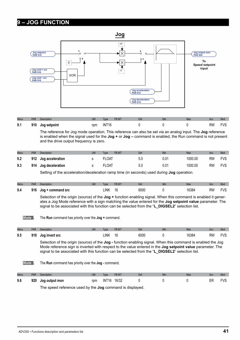
ADV200 • Functions description and parameters list 41
9–JOGFUNCTION
Jog
Jog setpointPAR 910
Jog cmd + srcPAR 916
+1
-1
Jog accelerationPAR 912
Jog decelerationPAR 914
Jog output monPAR 920
Jog cmd - srcPAR 916
0
F
TF
T
ToSpeed setpoint
input
XOR
Menu PAR Description UM Type FB BIT Def Min Max Acc Mod
9.1 910 Jogsetpoint rpm INT16 0 0 0 RW FVSThe reference for Jog mode operation. This reference can also be set via an analog input. The Jog reference is enabled when the signal used for the Jog+or Jog– command is enabled, the Run command is not present and the drive output frequency is zero.
Menu PAR Description UM Type FB BIT Def Min Max Acc Mod
9.2 912 Jogacceleration s FLOAT 5.0 0.01 1000.00 RW FVS9.3 914 Jogdeceleration s FLOAT 5.0 0.01 1000.00 RW FVS
Setting of the acceleration/deceleration ramp time (in seconds) used during Jog operation.
Menu PAR Description UM Type FB BIT Def Min Max Acc Mod
9.4 916 Jog+commandsrc LINK 16 6000 0 16384 RW FVSSelection of the origin (source) of the Jog+ function enabling signal. When this command is enabled it gener-ates a Jog Mode reference with a sign matching the value entered for the Jogsetpointvalue parameter. The signal to be associated with this function can be selected from the “L_DIGSEL�” selection list.
Note ! The Run command has priority over the Jog+ command.
Menu PAR Description UM Type FB BIT Def Min Max Acc Mod
9.5 918 Joginvertsrc LINK 16 6000 0 16384 RW FVSSelection of the origin (source) of the Jog- function enabling signal. When this command is enabled the Jog Mode reference sign is inverted with respect to the value entered in the Jogsetpointvalue parameter. The signal to be associated with this function can be selected from the “L_DIGSEL�” selection list.
Note ! The Run command has priority over the Jog-command.
Menu PAR Description UM Type FB BIT Def Min Max Acc Mod
9.6 920 Jogoutputmon rpm INT16 16/32 0 0 0 ER FVSThe speed reference used by the Jog command is displayed.

4� ADV200 • Functions description and parameters list
10–SPEEDMONITORFUNC
Spee
d/R
efer
ence
Spee
d/R
efer
ence
isze
roSp
eed/
Ref
eren
ceis
zero
dela
y
Zero delay
Zero thr
Speed Zero
Speed 0 thrPAR 940
Speed 0 delayPAR 942
Reference 0 thrPAR 930
Reference 0 delayPAR 932
Speed is zero delayPAR 946
Speed is zeroPAR 944
Ref is zero delayPAR 936
Ref is zeroPAR 934
Menu PAR Description UM Type FB BIT Def Min Max Acc Mod
10.1 930 Reference0thr rpm INT16 30 0 CALCI RW FVSSetting of the threshold for recognition of the speed = 0 reference. The value is valid for both directions of rota-tion.
Menu PAR Description UM Type FB BIT Def Min Max Acc Mod
10.2 932 Reference0delay ms UINT16 400 0 10000 RW FVSSetting of the delay in milliseconds after which the reference = 0 reached signal is enabled.
Menu PAR Description UM Type FB BIT Def Min Max Acc Mod
10.3 940 Speed0thr rpm INT16 30 0 CALCI RW FVSSetting of the threshold for recognizing speed value = 0. The value is valid for both directions of rotation.
Menu PAR Description UM Type FB BIT Def Min Max Acc Mod
10.4 942 Speed0delay ms UINT16 400 0 10000 RW FVSSetting of the delay in milliseconds after which the speed = 0 reached signal is enabled.
When the motor reaches a speed that is below the zero speed threshold, it stops and the n=0 LED lights up
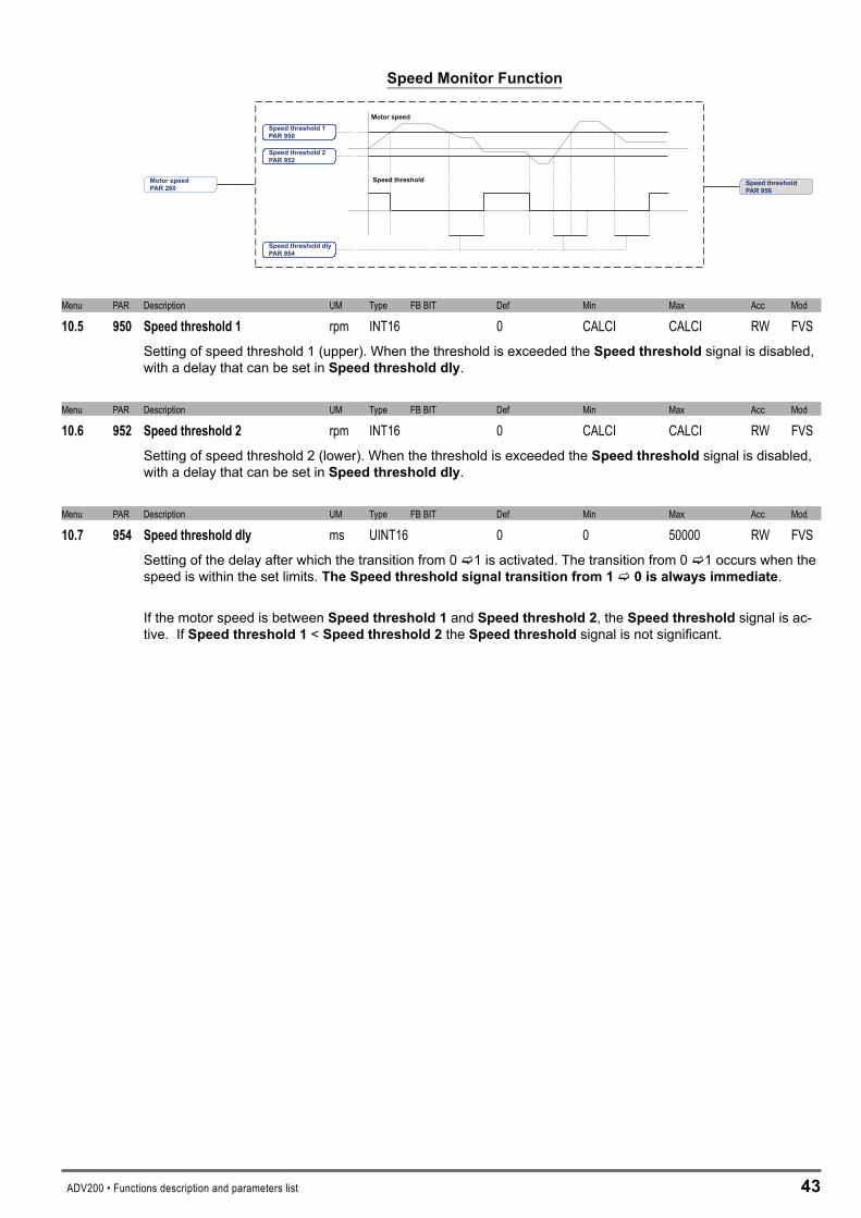
ADV200 • Functions description and parameters list 4�
Speed Monitor Function
Speed threshold 1PAR 950
Speed threshold 2PAR 952
Speed threshold dlyPAR 954
Motor speed
Speed threshold Speed thresholdPAR 956
Motor speedPAR 260
Menu PAR Description UM Type FB BIT Def Min Max Acc Mod
10.5 950 Speedthreshold1 rpm INT16 0 CALCI CALCI RW FVSSetting of speed threshold 1 (upper). When the threshold is exceeded the Speedthreshold signal is disabled, with a delay that can be set in Speedthresholddly.
Menu PAR Description UM Type FB BIT Def Min Max Acc Mod
10.6 952 Speedthreshold2 rpm INT16 0 CALCI CALCI RW FVSSetting of speed threshold 2 (lower). When the threshold is exceeded the Speedthreshold signal is disabled, with a delay that can be set in Speedthresholddly.
Menu PAR Description UM Type FB BIT Def Min Max Acc Mod
10.7 954 Speedthresholddly ms UINT16 0 0 50000 RW FVSSetting of the delay after which the transition from 0 c1 is activated. The transition from 0 c1 occurs when the speed is within the set limits.TheSpeedthresholdsignaltransitionfrom1c0isalwaysimmediate.
If the motor speed is between Speedthreshold1 and Speedthreshold�, the Speedthresholdsignal is ac-tive. If Speedthreshold1 < Speedthreshold� the Speedthresholdsignal is not significant.
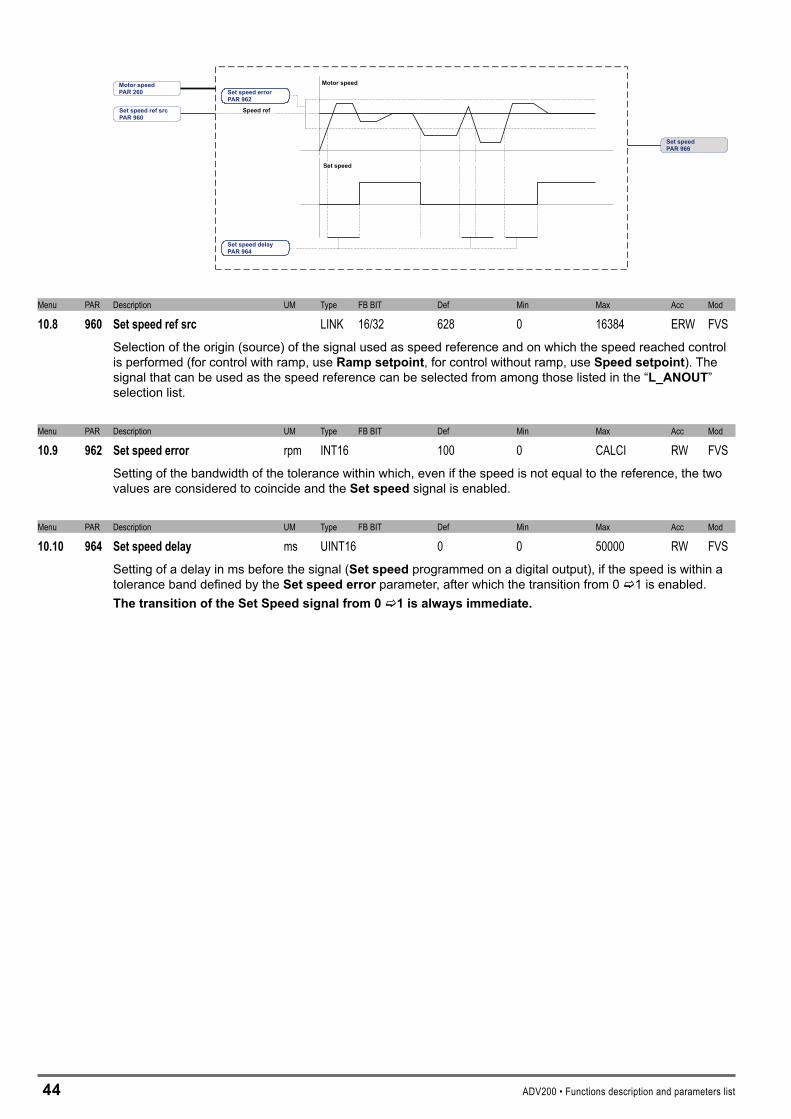
44 ADV200 • Functions description and parameters list
Set speed errorPAR 962
Motor speed
Set speed
Set speed ref srcPAR 960
Set speedPAR 966
Set speed delayPAR 964
Speed ref
Motor speedPAR 260
Menu PAR Description UM Type FB BIT Def Min Max Acc Mod
10.8 960 Setspeedrefsrc LINK 16/32 628 0 16384 ERW FVSSelection of the origin (source) of the signal used as speed reference and on which the speed reached control is performed (for control with ramp, use Rampsetpoint, for control without ramp, use Speedsetpoint). The signal that can be used as the speed reference can be selected from among those listed in the “L_ANOUT” selection list.
Menu PAR Description UM Type FB BIT Def Min Max Acc Mod
10.9 962 Setspeederror rpm INT16 100 0 CALCI RW FVSSetting of the bandwidth of the tolerance within which, even if the speed is not equal to the reference, the two values are considered to coincide and the Setspeed signal is enabled.
Menu PAR Description UM Type FB BIT Def Min Max Acc Mod
10.10 964 Setspeeddelay ms UINT16 0 0 50000 RW FVSSetting of a delay in ms before the signal (Setspeed programmed on a digital output), if the speed is within a tolerance band defined by the Setspeederror parameter, after which the transition from 0 c1 is enabled. ThetransitionoftheSetSpeedsignalfrom0c1isalwaysimmediate.
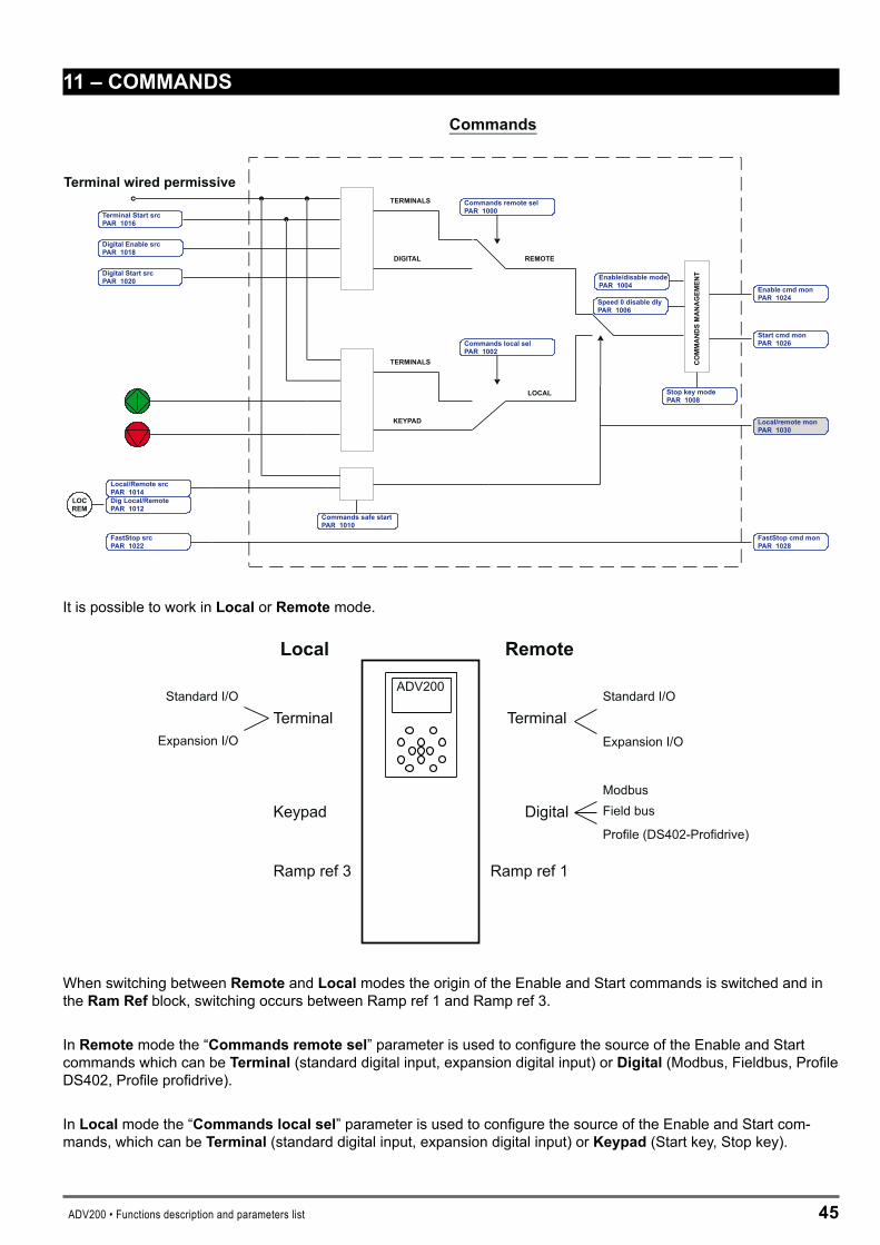
ADV200 • Functions description and parameters list 45
11–COMMANDS
Commands
Terminal wired permissive
DIGITAL
KEYPAD
Start cmd monPAR 1026
FastStop cmd monPAR 1028
LOCREM
FastStop srcPAR 1022
COMMANDSMANAGEMENTEnable/disable mode
PAR 1004
Speed 0 disable dlyPAR 1006
TERMINALS
Digital Enable srcPAR 1018
Terminal Start srcPAR 1016
Digital Start srcPAR 1020
REMOTE
Commands remote selPAR 1000
TERMINALS
LOCAL
Commands localR 1002
selPA
Local/Remote srcPAR 1014Dig Local/RemotePAR 1012
Local/remote monPAR 1030
Commands safe startPAR 1010
Stop key modePAR 1008
It is possible to work in Local or Remote mode.
ADV200
Local Remote
Keypad
TerminalStandard I/O
Expansion I/O
ModbusField bus
Profile (DS402-Profidrive)
TerminalStandard I/O
Expansion I/O
Digital
Ramp ref 3 Ramp ref 1
When switching between Remote and Local modes the origin of the Enable and Start commands is switched and in the RamRef block, switching occurs between Ramp ref 1 and Ramp ref 3.
In Remote mode the “Commandsremotesel” parameter is used to configure the source of the Enable and Start commands which can be Terminal (standard digital input, expansion digital input) or Digital (Modbus, Fieldbus, Profile DS402, Profile profidrive).
In Local mode the “Commandslocalsel” parameter is used to configure the source of the Enable and Start com-mands, which can be Terminal (standard digital input, expansion digital input) or Keypad (Start key, Stop key).
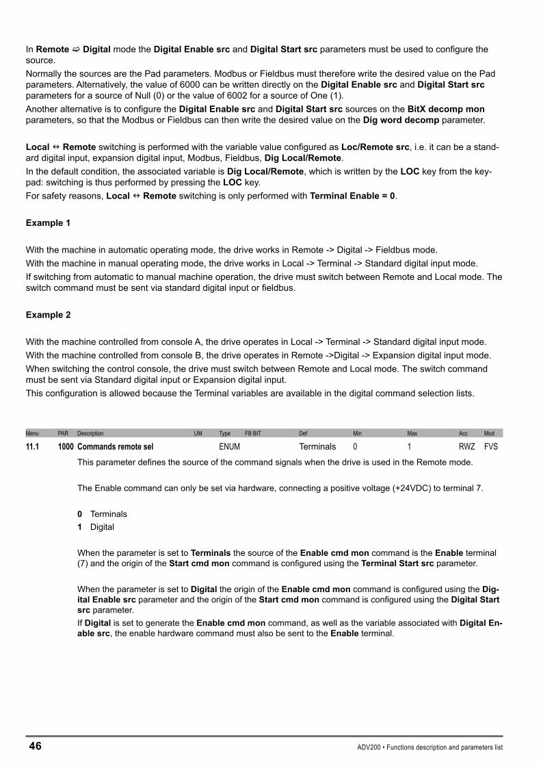
46 ADV200 • Functions description and parameters list
In RemotecDigital mode the DigitalEnablesrc and DigitalStartsrc parameters must be used to configure the source.Normally the sources are the Pad parameters. Modbus or Fieldbus must therefore write the desired value on the Pad parameters. Alternatively, the value of 6000 can be written directly on the DigitalEnablesrc and DigitalStartsrc parameters for a source of Null (0) or the value of 6002 for a source of One (1). Another alternative is to configure the DigitalEnablesrc and DigitalStartsrc sources on the BitXdecompmon parameters, so that the Modbus or Fieldbus can then write the desired value on the Digworddecomp parameter.
LocalnRemote switching is performed with the variable value configured as Loc/Remotesrc, i.e. it can be a stand-ard digital input, expansion digital input, Modbus, Fieldbus, DigLocal/Remote.In the default condition, the associated variable is DigLocal/Remote, which is written by the LOC key from the key-pad: switching is thus performed by pressing the LOC key.For safety reasons,LocalnRemote switching is only performed with TerminalEnable=0.
Example1
With the machine in automatic operating mode, the drive works in Remote -> Digital -> Fieldbus mode.With the machine in manual operating mode, the drive works in Local -> Terminal -> Standard digital input mode.If switching from automatic to manual machine operation, the drive must switch between Remote and Local mode. The switch command must be sent via standard digital input or fieldbus.
Example�
With the machine controlled from console A, the drive operates in Local -> Terminal -> Standard digital input mode.With the machine controlled from console B, the drive operates in Remote ->Digital -> Expansion digital input mode.When switching the control console, the drive must switch between Remote and Local mode. The switch command must be sent via Standard digital input or Expansion digital input.This configuration is allowed because the Terminal variables are available in the digital command selection lists.
Menu PAR Description UM Type FB BIT Def Min Max Acc Mod
11.1 1000 Commandsremotesel ENUM Terminals 0 1 RWZ FVSThis parameter defines the source of the command signals when the drive is used in the Remote mode.
The Enable command can only be set via hardware, connecting a positive voltage (+24VDC) to terminal 7.
0 Terminals1 Digital
When the parameter is set to Terminals the source of the Enablecmdmon command is the Enable terminal (7) and the origin of the Startcmdmon command is configured using the TerminalStartsrc parameter.
When the parameter is set to Digital the origin of the Enablecmdmon command is configured using the Dig-italEnablesrc parameter and the origin of the Startcmdmon command is configured using the DigitalStartsrc parameter. If Digital is set to generate the Enablecmdmon command, as well as the variable associated with DigitalEn-ablesrc, the enable hardware command must also be sent to the Enable terminal.

ADV200 • Functions description and parameters list 47
Menu PAR Description UM Type FB BIT Def Min Max Acc Mod
11.2 1002 Commandslocalsel ENUM Keypad 0 2 ERWZ FVSThis parameter defines the source of the command signals when the drive is used in the Local mode.
0 Terminals � Keypad
When the parameter is set to Terminals the source of the Enablecmdmon command is the Enable terminal (7) and the origin of theStartcmdmon command is configured using the TerminalStartsrc parameter.
When the parameter is set to Keypad the origin of the Enablecmdmon and Startcmdmon commands is the Start key. When Keypad is set to generate the Enablecmdmon command, as well as the Start key the enable hardware command must also be sent to the Enable terminal.
Menu PAR Description UM Type FB BIT Def Min Max Acc Mod
11.3 1004 Enable/disablemode ENUM Stop/FS&Spd=0 0 3 ERW FVSThis parameter is used to define the generation of Enablecmdmon, i.e. to configure the type of control used for enabling and disabling the drive.
0 Off 1 Stop/FS&Spd = 0 � Stop&Spd = 0 � FS&Spd = 0
If set to 0Off:
In Terminal mode the drive is enabled and disabled via the Enable terminal.In Digital mode the drive is enabled and disabled when the signal on the Enable terminal and the DigitalEn-able command are present simultaneously.In Keypad mode the drive is enabled if the hardware is enabled on the Enable terminal and the Start key is pressed.In Keypad mode it is disabled if the hardware is not enabled on the Enable terminal or if the Stop key is pressed twice.
If 1Stop/FS&Spd=0 is set:
In Terminal mode the drive is enabled when the hardware is enabled on the Enable terminal, on the terminal programmed as TerminalStart and the FastStop terminal must not be enabled.In Terminal mode the drive is instantly disabled if there is no signal on the Enable terminal, or when speed=0 is reached if the Startcommand is disabled or the terminal programmed as FastStop is enabled.In Digital mode the drive is enabled when the hardware is enabled on the Enable terminal, the DigitalEnable, In Digital mode the drive is instantly disabled if there is no signal on the Enable terminal, or when speed=0 is reached if the DigitalStart command is disabled or the terminal programmed as FastStop is enabled.In Keypad mode the drive is enabled if the hardware is enabled on the Enable terminal and the Start key is pressed, with the command disabled on the FastStop terminal.In Keypad mode the drive is disabled instantly if the signal is not present on the Enable terminal or the Stop key is pressed twice.
4� ADV200 • Functions description and parameters list
If �Stop&Spd=0is set:
In Terminal mode the drive is enabled if the hardware is enabled on the Enable terminal and the signal is ena-bled on the terminal programmed as TerminalStart.In Terminal mode the drive is instantly disabled if there is no signal on the Enable terminal, or if, upon reaching the speed=0, the TerminalStart command is disabled.In Digital mode the drive is enabled when the hardware is enabled on the Enable terminal and the DigitalEn-able and DigitalStart signals are present.In Digital mode the drive is instantly disabled if the signal is not present on the Enable terminal, or the DigitalEnable command is not present, or upon reaching the speed=0 if the DigitalStart command is set to 0.In Keypad mode the drive is enabled when the hardware is enabled on the Enable terminal and the Start key is pressed.In Keypad mode the drive is instantly disabled if the signal is not present on the Enable terminal or the Stop key is pressed twice, or when the speed=0 is reached if the Stop key is pressed.
If �FS&Spd=0 is set:
In Terminal mode the drive is enabled when the hardware is enabled on the Enable terminal and the FastStopterminal is not enabled.In Terminal mode the drive is instantly disabled if there is no signal on the Enable terminal, or when the speed=0 is reached if the terminal programmed as FastStopis enabled.In Digital mode the drive is enabled if the hardware is enabled on the Enable terminal and the DigitalEnable signal is present, with the command on the FastStop terminal disabled.In Digital mode the drive is instantly disabled if there is no signal on the Enable terminal, or no DigitalEnable command, or when the speed=0 is reached if the DigitalStart command is set to 0.In Keypad mode the drive is enabled if the hardware is enabled on the Enable terminal and the Startkey is pressed, with the FastStop command disabled.In Keypad mode the drive is instantly disabled if there is no signal on the Enable terminal or the Stop key is pressed twice, or if, when the speed=0 is reached, the terminal programmed as FastStop is enabled.
Menu PAR Description UM Type FB BIT Def Min Max Acc Mod
11.4 1006 Speed0disabledly ms UINT16 1000 0 10000 ERW FVSSetting of a delay in milliseconds between reaching the zero speed and disabling the drive when Enable/Dis-ablemode is set to a value other than Off.
Menu PAR Description UM Type FB BIT Def Min Max Acc Mod
11.5 1008 Stopkeymode ENUM Inactive 0 1 ERW FVSSetting of the stop key functioning on the keypad in case of Remote->Terminal or Remote->Digital or Local->Terminal mode. In Local -> Keypad mode this configuration is ineffective.
0 Inactive 1 EmgStop&Alarm
If the command is set to Inactive, pressing the Stop key on the keypad is ineffective.If the command is set to EmgStop&Alarm, when the Stop key is pressed the motor stops in FastStop mode and the Emgstopalarm is generated. When the motor reaches the speed=0, the drive is automatically disa-bled and waits for the Faultreset command. The Faultreset command must be sent twice to reset the drive.
ADV200 • Functions description and parameters list 49
Menu PAR Description UM Type FB BIT Def Min Max Acc Mod
11.6 1010 Commandssafestart BIT 0 0 1 ERW FVSThis parameter is used to define whether the safe start command is disabled or enabled at drive power-on.
0 Off1 On
If set to Off, the safe start command is disabled. If the drive is powered-on with the hardware enabled on the Enable terminal, the motor could start rotating.When set to On, the safe start command is enabled. If the drive is powered-on with the hardware enabled on the Enable terminal, the motor will not rotate. To set the drive to accept subsequent commands, open the hard-ware enabling contact on the Enable terminal and then close it again.
Menu PAR Description UM Type FB BIT Def Min Max Acc Mod
11.7 1012 Diglocal/remote ENUM 16 Remote 0 1 ERW FVSSetting Local or Remote operating mode.
0 Local 1 Remote
Writing this parameter is only effective if it is associated with Local/Remotesrc and if performed without the hardware enabled on the Enable terminal. Press LOC to modify the value of this parameter 0<->1. To disable the LOC key, set Local/Remotesrc to a value other than Diglocal/remote.
Menu PAR Description UM Type FB BIT Def Min Max Acc Mod
11.8 1014 Local/remotesrc LINK 16 1012 0 16384 ERW FVSSelection of the origin (source) of the signal that switches between Remote and Local. Switching can only be performed if the hardware is not enabled on the Enable terminal.The signal to be associated with this function can be selected from the “L_DIGSEL�” selection list.
0 Local 1 Remote
In Remote mode the “Commandsremotesel” parameter is used to configure the source of the Enable and Start commands, which can be Terminal (standard digital input, expansion digital input) or Digital (Modbus, Fieldbus, Profile DS402, Profile profidrive).
In Local mode the “Commandslocalsel” parameter is used to configure the source of the Enable and Start commands, which can be Terminal (standard digital input, expansion digital input) or Keypad (Start key, Stop key).
Menu PAR Description UM Type FB BIT Def Min Max Acc Mod
11.9 1016 TerminalStartsrc LINK 16 1048 0 16384 ERW FVSSelection of the origin (source) of the TerminalStart signal. Switching can only be performed if the hardware is not enabled on the Enable terminal.The signal to be associated with this function can be selected from the “L_DIGSEL�” selection list.
In the default condition, the origin of the Terminal Start signal is the Start output of the ForwardReverseControl (FRC) block.

50 ADV200 • Functions description and parameters list
Menu PAR Description UM Type FB BIT Def Min Max Acc Mod
11.10 1018 DigitalEnablesrc LINK 16 6000 0 16384 ERW FVSSelection of the origin (source) of the signal that defines the enabling of the drive when the commands are sent via serial line or fieldbus. The command to be associated with this function can be selected from the “L_DIG-SEL�” selection list.
Menu PAR Description UM Type FB BIT Def Min Max Acc Mod
11.11 1020 DigitalStartsrc LINK 16 6000 0 16384 ERW FVSSelection of the origin (source) of the Digital Start signal. The signal to be associated with this function can be selected from the “L_DIGSEL�” selection list.
Menu PAR Description UM Type FB BIT Def Min Max Acc Mod
11.12 1022 FastStopsrc LINK 16 6000 0 16384 ERW FVSSelection of the origin (source) for the fast stop signal (FastStop). The terminal to be associated with this func-tion can be selected from the “L_DIGSEL�” selection list. During the execution of the FastStop command the ramps used are Accelerationtime� and Decelerationtime�.
Menu PAR Description UM Type FB BIT Def Min Max Acc Mod
11.13 1024 Enablecmdmon BIT 16 0 0 1 R FVSThe status of the enable command is displayed.
Menu PAR Description UM Type FB BIT Def Min Max Acc Mod
11.14 1026 Startcmdmon BIT 16 0 0 1 R FVSThe status of the Start command is displayed.
Menu PAR Description UM Type FB BIT Def Min Max Acc Mod
11.15 1028 FastStopcmdmon BIT 16 0 0 1 R FVSThe status of the FastStop command is displayed.
Menu PAR Description UM Type FB BIT Def Min Max Acc Mod
11.16 1040 FRmode ENUM Normal 0 2 ERWZ FVSSetting of the operating mode of the Forward Reverse Control (FRC) block.
0 Normal 1 Two wire Controllo a due fili� Three wire Controllo a tre fili
The default use of the FRC block is shown below.The Start command is linked to the Start terminal and the Reverse command is linked to Ramp ref invert.
FRC
FR start mon
FR reverse mon
FR cmd mon
COMMANDS
FR forward src
FR reverse src
FR stop src
Terminal start srcStart cmd mon
RAMP REF
Ramp ref invert src

ADV200 • Functions description and parameters list 51
The function diagrams of the 3 modes are shown below.
Normal
Two wire
Three wire
Forwardstart
Forwardstart
Reverse
Start
Start
Stop
MotorSpeed
MotorSpeed
MotorSpeed
Reverse
Reverse
Forwardstart
Start
FRC
FR forward src1042PAR
FR reverse src1044PAR
FR *stop src1046PAR
FR mode1040PAR
FR start monPAR 1048
FR reverse monPAR 1050
FR cmd monPAR 1052
When 0-Normal control is set the motor only starts rotating when the FRForward command is sent. If the FRReverse command is present the motor rotates in the reverse direction, The FRstartmon output repeats the status of the FRForward command, while the FRreversemon output repeats the status of theFRReverse command.
When set to 1-Twowire control, the motor only rotates if the FRForward command or FRReverse com-mand is present. The simultaneous presence of the FRForward and FRReverse commands causes the motor to stop.The FRstartmon output is enabled if the FRForward and FRReverse commands are not present simultaneously.The FRreversemon output repeats the status of the FRReverse command.
For �-Threewire control the FR*stop command must be present on a digital input programmed via the FR*stopsrc parameter (not present in the default condition). When set to Threewire control, the motor starts upon receiving an impulse of not less than 50 msec on the FRForward terminal. Once the motor has started the command is no longer necessary on the FRForward terminal. To reverse the direction of rotation enable the FR Reverse command: the motor will be brought to the zero speed with the set ramp and will restart in the opposite direction of rotation. The motor rotates in the Reverse direction for as long as the FR Reverse signal is enabled. If the FRReverse signal is disabled the motor rotates in the Forward direction. To stop the motor open the FR *stop contact.
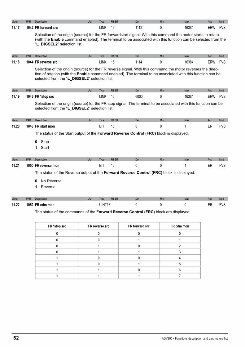
5� ADV200 • Functions description and parameters list
Menu PAR Description UM Type FB BIT Def Min Max Acc Mod
11.17 1042 FRforwardsrc LINK 16 1112 0 16384 ERW FVSSelection of the origin (source) for the FR forwardstart signal. With this command the motor starts to rotate (with the Enable command enabled). The terminal to be associated with this function can be selected from the “L_DIGSEL�” selection list.
Menu PAR Description UM Type FB BIT Def Min Max Acc Mod
11.18 1044 FRreversesrc LINK 16 1114 0 16384 ERW FVSSelection of the origin (source) for the FR reverse signal. With this command the motor reverses the direc-tion of rotation (with the Enable command enabled). The terminal to be associated with this function can be selected from the “L_DIGSEL�” selection list.
Menu PAR Description UM Type FB BIT Def Min Max Acc Mod
11.19 1046 FR*stopsrc LINK 16 6000 0 16384 ERW FVSSelection of the origin (source) for the FR stop signal. The terminal to be associated with this function can be selected from the “L_DIGSEL�” selection list.
Menu PAR Description UM Type FB BIT Def Min Max Acc Mod
11.20 1048 FRstartmon BIT 16 0 0 1 ER FVSThe status of the Start output of the ForwardReverseControl(FRC) block is displayed.
0 Stop 1 Start
Menu PAR Description UM Type FB BIT Def Min Max Acc Mod
11.21 1050 FRreversemon BIT 16 0 0 1 ER FVSThe status of the Reverse output of the ForwardReverseControl(FRC) block is displayed.
0 No Reverse 1 Reverse
Menu PAR Description UM Type FB BIT Def Min Max Acc Mod
11.22 1052 FRcdmmon UINT16 0 0 0 ER FVSThe status of the commands of the ForwardReverseControl(FRC)block are displayed.
FR*stopsrc FRreversesrc FRforwardsrc FRcdmmon
0 0 0 00 0 1 10 1 0 20 1 1 31 0 0 41 0 1 51 1 0 61 1 1 7
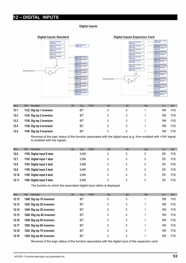
ADV200 • Functions description and parameters list 5�
1�–DIGITALINPUTS
F
T
F
T
Terminal inputs Std
Terminal input Exp
Digital Inputs
Dig inp 1 inversionPAR 1132
Dig inp 2 inversionPAR 1134
Dig inp 3 inversionPAR 1136
Dig inp 4 inversionPAR 1138
Dig inp 5 inversionPAR 1140
Dig inp 1X inversionPAR 1240
Dig inp 2X inversionPAR 1242
Dig inp 3X inversionPAR 1244
Dig inp 4X inversionPAR 1246
Dig inp 5X inversionPAR 1248
Dig inp 6X inversionPAR 1250
Dig inp 7X inversionPAR 1252
Dig inp 8X inversionPAR 1254
Digital Inputs Standard Digital Inputs Expansion Card
Digital input E destPAR 1150
Digital input E monPAR 1110
Digital input 1 destPAR 1152
Digital input 1 monPAR 1112
Digital input 2 destPAR 1154
Digital input 2 monPAR 1114
Digital input 3 destPAR 1156
Digital input 3 monPAR 1116
Digital input 4 destPAR 1158
Digital input 4 monPAR 1118
Digital input 5 destPAR 1160
Digital input 5 monPAR 1120
Dig input 1X destPAR 1270
Digital input 1X monPAR 1210
Dig input 2X destPAR 1272
Digital input 2X monPAR 1212
Dig input 3X destPAR 1274
Digital input 3X monPAR 1214
Dig input 4X destPAR 1276
Digital input 4X monPAR 1216
Dig input 5X destPAR 1278
Digital input 5X monPAR1218
Dig input 6X destPAR 1280
Digital input X6 monPAR 1220
Dig input 8X destPAR 1282
Digital input 7X monPAR 1222
Dig input 9X destPAR 1284
Digital input 8X monPAR 1224
Digital input monPAR 1100
Digital input X monPAR 1200
Menu PAR Description UM Type FB BIT Def Min Max Acc Mod
12.1 1132 Diginp1inversion BIT 0 0 1 RW FVS12.2 1134 Diginp2inversion BIT 0 0 1 RW FVS12.3 1136 Diginp3inversion BIT 0 0 1 RW FVS12.4 1138 Diginp4inversion BIT 0 0 1 RW FVS12.5 1140 Diginp5inversion BIT 0 0 1 RW FVS
Reversal of the logic status of the function associated with the digital input (e.g. from enabled with +24V signal to enabled with low signal).
Menu PAR Description UM Type FB BIT Def Min Max Acc Mod
12.6 1150 DigitalinputEdest ILINK 0 0 0 ER FVS12.7 1152 Digitalinput1dest ILINK 0 0 0 ER FVS12.8 1154 Digitalinput2dest ILINK 0 0 0 ER FVS12.9 1156 Digitalinput3dest ILINK 0 0 0 ER FVS12.10 1158 Digitalinput4dest ILINK 0 0 0 ER FVS12.11 1160 Digitalinput5dest ILINK 0 0 0 ER FVS
The function to which the associated digital input refers is displayed.
Menu PAR Description UM Type FB BIT Def Min Max Acc Mod
12.12 1240 Diginp1Xinversion BIT 0 0 1 RW FVS12.13 1242 Diginp2Xinversion BIT 0 0 1 RW FVS12.14 1244 Diginp3Xinversion BIT 0 0 1 RW FVS12.15 1246 IDiginp4Xinversion BIT 0 0 1 RW FVS12.16 1248 Diginp5Xinversion BIT 0 0 1 RW FVS12.17 1250 Diginp6Xinversion BIT 0 0 1 RW FVS12.18 1252 Diginp7Xinversion BIT 0 0 1 RW FVS12.19 1254 Diginp8Xinversion BIT 0 0 1 RW FVS
Reversal of the logic status of the function associated with the digital input of the expansion card.

54 ADV200 • Functions description and parameters list
Menu PAR Description UM Type FB BIT Def Min Max Acc Mod
12.20 1270 Diginput1Xdest ILINK 0 0 0 ER FVS12.21 1272 Diginput2Xdest ILINK 0 0 0 ER FVS12.22 1274 Diginput3Xdest ILINK 0 0 0 ER FVS12.23 1276 Diginput4Xdest ILINK 0 0 0 ER FVS12.24 1278 Diginput5Xdest ILINK 0 0 0 ER FVS12.25 1280 Diginput6Xdest ILINK 0 0 0 ER FVS12.26 1282 Diginput7Xdest ILINK 0 0 0 ER FVS12.27 1284 Diginput8Xdest ILINK 0 0 0 ER FVS
Selection of the destination of the associated digital input of the expansion card.
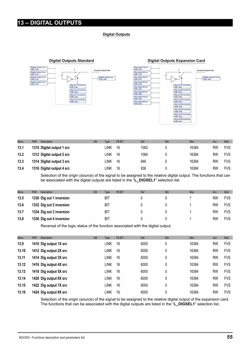
ADV200 • Functions description and parameters list 55
1�–DIGITALOUTPUTS
F
T
Terminal Outputs Std F
T
Terminal Outputs Exp
Digital Outputs
Dig out 1 inversionPAR 1330
Dig out 2 inversionPAR 1332
Dig out 3 inversionPAR 1334
Dig out 4 inversionPAR 1336
Digital Outputs StandardDigital output 1 srcPAR 1310
Digital output 2 srcPAR 1312
Digital output 3 srcPAR 1314
Digital output 4 srcPAR 1316 Dig out 1X inversion
PAR 1430
Dig out 2X inversionPAR 1432
Dig out 3X inversionPAR 1434
Dig out 4X inversionPAR 1436
Dig output 2X srcPAR 1412
DigAR 1414
output 3X srcP
DigAR 1416
output 4X srcP
Digital Outputs Expansion Card
DigAR 1418
output 5X srcP
DigAR 1420
output 6X srcP
DigAR 1422
output 7X srcP
DigAR 1424
output 8X srcP Dig out 5X inversion
PAR 1438
Dig out 6X inversionPAR 1440
Dig out 7X inversionPAR 1442
Dig out 8X inversionPAR 1444
Digital output monPAR 1300
Digital output X monPAR 1400
Dig output 1X srcPAR 1410
Menu PAR Description UM Type FB BIT Def Min Max Acc Mod
13.1 1310 Digitaloutput1src LINK 16 1062 0 16384 RW FVS13.2 1312 Digitaloutput2src LINK 16 1064 0 16384 RW FVS13.3 1314 Digitaloutput3src LINK 16 946 0 16384 RW FVS13.4 1316 Digitaloutput4src LINK 16 936 0 16384 RW FVS
Selection of the origin (source) of the signal to be assigned to the relative digital output. The functions that can be associated with the digital outputs are listed in the “L_DIGSEL1” selection list.
Menu PAR Description UM Type FB BIT Def Min Max Acc Mod
13.5 1330 Digout1inversion BIT 0 0 1 RW FVS13.6 1332 Digout2inversion BIT 0 0 1 RW FVS13.7 1334 Digout3inversion BIT 0 0 1 RW FVS13.8 1336 Digout4inversion BIT 0 0 1 RW FVS
Reversal of the logic status of the function associated with the digital output.
Menu PAR Description UM Type FB BIT Def Min Max Acc Mod
13.9 1410 Digoutput1Xsrc LINK 16 6000 0 16384 RW FVS13.10 1412 Digoutput2Xsrc LINK 16 6000 0 16384 RW FVS13.11 1414 Digoutput3Xsrc LINK 16 6000 0 16384 RW FVS13.12 1416 Digoutput4Xsrc LINK 16 6000 0 16384 RW FVS13.13 1418 Digoutput5Xsrc LINK 16 6000 0 16384 RW FVS13.14 1420 Digoutput6Xsrc LINK 16 6000 0 16384 RW FVS13.15 1422 Digoutput7Xsrc LINK 16 6000 0 16384 RW FVS13.16 1424 Digoutput8Xsrc LINK 16 6000 0 16384 RW FVS
Selection of the origin (source) of the signal to be assigned to the relative digital output of the expansion card. The functions that can be associated with the digital outputs are listed in the “L_DIGSEL1” selection list.
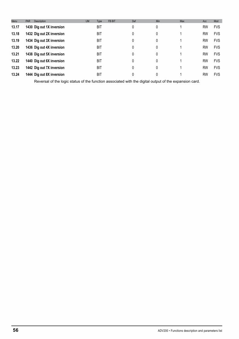
56 ADV200 • Functions description and parameters list
Menu PAR Description UM Type FB BIT Def Min Max Acc Mod
13.17 1430 Digout1Xinversion BIT 0 0 1 RW FVS13.18 1432 Digout2Xinversion BIT 0 0 1 RW FVS13.19 1434 Digout3Xinversion BIT 0 0 1 RW FVS13.20 1436 Digout4Xinversion BIT 0 0 1 RW FVS13.21 1438 Digout5Xinversion BIT 0 0 1 RW FVS13.22 1440 Digout6Xinversion BIT 0 0 1 RW FVS13.23 1442 Digout7Xinversion BIT 0 0 1 RW FVS13.24 1444 Digout8Xinversion BIT 0 0 1 RW FVS
Reversal of the logic status of the function associated with the digital output of the expansion card.
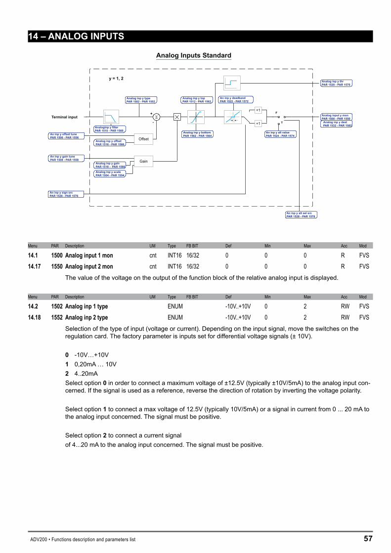
ADV200 • Functions description and parameters list 57
14–ANALOGINPUTS
Terminal input+
- +1
+1F
T
y = 1, 2
Offset
Gain
Analog Inputs Standard
Analog inp y typePAR 1502 - PAR 1552
An inp y offset tunePAR 1506 - PAR 1556
Analog inp y offsetPAR 1516 - PAR 1566
An inp y gain tunePAR 1508 - PAR 1558
Analog inp y gainPAR 1518 - PAR 1568
Analog inp y scalePAR 1504 - PAR 1554
Analog inp y bottomPAR 1562 - PAR 1564
Analog inp y topPAR 1512 - PAR 1562
An inp y alt valuePAR 1524 - PAR 1574
An inp y alt sel srcPAR 1528 - PAR 1578
Analog inp y thrPAR 1520 - PAR 1570
Analog input y monPAR 1500 - PAR 1550Analog inp y destPAR 1532 - PAR 1582Analoginp y filter
PAR 1510 - PAR 1560
An inp y deadbandPAR 1522 - PAR 1572
An inp y sign srcPAR 1526 - PAR 1576
Menu PAR Description UM Type FB BIT Def Min Max Acc Mod
14.1 1500 Analoginput1mon cnt INT16 16/32 0 0 0 R FVS14.17 1550 Analoginput2mon cnt INT16 16/32 0 0 0 R FVS
The value of the voltage on the output of the function block of the relative analog input is displayed.
Menu PAR Description UM Type FB BIT Def Min Max Acc Mod
14.2 1502 Analoginp1type ENUM -10V..+10V 0 2 RW FVS14.18 1552 Analoginp2type ENUM -10V..+10V 0 2 RW FVS
Selection of the type of input (voltage or current). Depending on the input signal, move the switches on the regulation card. The factory parameter is inputs set for differential voltage signals (± 10V).
0 -10V…+10V 1 0,20mA … 10V � 4..20mA Select option 0 in order to connect a maximum voltage of ±12.5V (typically ±10V/5mA) to the analog input con-cerned. If the signal is used as a reference, reverse the direction of rotation by inverting the voltage polarity.
Select option 1 to connect a max voltage of 12.5V (typically 10V/5mA) or a signal in current from 0 ... 20 mA to the analog input concerned. The signal must be positive.
Select option � to connect a current signal of 4...20 mA to the analog input concerned. The signal must be positive.
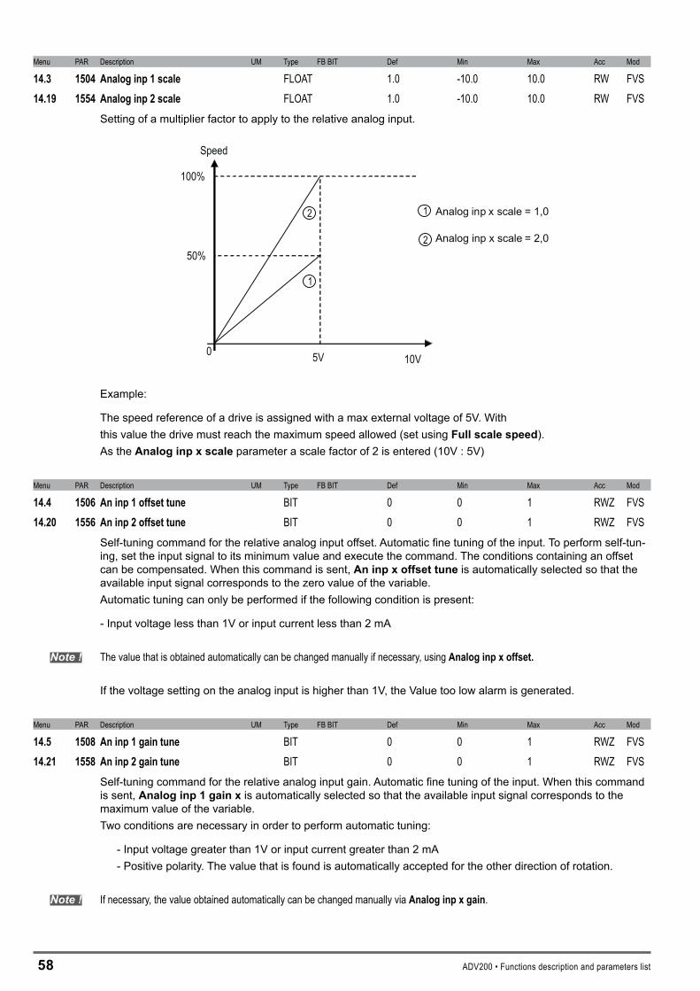
5� ADV200 • Functions description and parameters list
Menu PAR Description UM Type FB BIT Def Min Max Acc Mod
14.3 1504 Analoginp1scale FLOAT 1.0 -10.0 10.0 RW FVS14.19 1554 Analoginp2scale FLOAT 1.0 -10.0 10.0 RW FVS
Setting of a multiplier factor to apply to the relative analog input.
1
2 1
2
Analog inp x scale = 1,0
Analog inp x scale = 2,0
0 10V
100%
50%
5V
Speed
Example:
The speed reference of a drive is assigned with a max external voltage of 5V. Withthis value the drive must reach the maximum speed allowed (set using Fullscalespeed).As the Analoginpxscale parameter a scale factor of 2 is entered (10V : 5V)
Menu PAR Description UM Type FB BIT Def Min Max Acc Mod
14.4 1506 Aninp1offsettune BIT 0 0 1 RWZ FVS14.20 1556 Aninp2offsettune BIT 0 0 1 RWZ FVS
Self-tuning command for the relative analog input offset. Automatic fine tuning of the input. To perform self-tun-ing, set the input signal to its minimum value and execute the command. The conditions containing an offset can be compensated. When this command is sent, Aninpxoffsettune is automatically selected so that the available input signal corresponds to the zero value of the variable.Automatic tuning can only be performed if the following condition is present:
- Input voltage less than 1V or input current less than 2 mA
Note ! The value that is obtained automatically can be changed manually if necessary, using Analoginpxoffset.
If the voltage setting on the analog input is higher than 1V, the Value too low alarm is generated.
Menu PAR Description UM Type FB BIT Def Min Max Acc Mod
14.5 1508 Aninp1gaintune BIT 0 0 1 RWZ FVS14.21 1558 Aninp2gaintune BIT 0 0 1 RWZ FVS
Self-tuning command for the relative analog input gain. Automatic fine tuning of the input. When this command is sent, Analoginp1gainx is automatically selected so that the available input signal corresponds to the maximum value of the variable.Two conditions are necessary in order to perform automatic tuning:
- Input voltage greater than 1V or input current greater than 2 mA - Positive polarity. The value that is found is automatically accepted for the other direction of rotation.
Note ! If necessary, the value obtained automatically can be changed manually via Analoginpxgain.

ADV200 • Functions description and parameters list 59
To perform self-tuning, set the input signal to its maximum value and execute the command. A multiplier factor is calculated to apply to the input signal value (not considering the Analoginpscale parameter) to reach the full scale value.
If the voltage setting on the analog input is less than 1V, the Value too low alarm is generated.
Menu PAR Description UM Type FB BIT Def Min Max Acc Mod
14.6 1510 Analoginp1filter ms FLOAT 10.0 1.0 100.0 ERW FVS14.22 1560 Analoginp2filter ms FLOAT 10.0 1.0 100.0 ERW FVS
Filter on the measurement of the corresponding analog input. This parameter can be used to control the re-sponse of the analog input and reduce any possible noise and interference.
Menu PAR Description UM Type FB BIT Def Min Max Acc Mod
14.7 1512 Analoginp1top cnt INT16 16384 -32768 32767 ERW FVS14.23 1562 Analoginp2top cnt INT16 16384 -32768 32767 ERW FVS
Setting of the upper speed reference limit as a function of the voltage (or current) of the relative analog refer-ence.
Menu PAR Description UM Type FB BIT Def Min Max Acc Mod
14.8 1514 Analoginp1bottom cnt INT16 -16384 -32768 32767 ERW FVS14.24 1564 Analoginp2bottom cnt INT16 -16384 -32768 32767 ERW FVS
Setting of the lower speed reference limit as a function of the voltage (or current) of the relative analog refer-ence.
Menu PAR Description UM Type FB BIT Def Min Max Acc Mod
14.9 1516 Offsetingan1 cnt INT16 0 -32768 32767 ERW FVS14.25 1566 Offsetingan2 cnt INT16 0 -32768 32767 ERW FVS
Setting of a value to compensate the condition in which the analog signal contains an offset, or when the vari-able assigned to the input already has a value even though no signal is connected.
0 10V
100%
Analog inp x offset {

60 ADV200 • Functions description and parameters list
Menu PAR Description UM Type FB BIT Def Min Max Acc Mod
14.10 1518 Analoginp1gain FLOAT 1.0 -10.0 10.0 ERW FVS14.26 1568 Analoginp2gain FLOAT 1.0 -10.0 10.0 ERW FVS
This parameter contains the value of the multiplier factor to apply to the analog reference calculated using the Analoginpgaintune function.
Example:
An external analog reference only reaches a maximum of 9.8V instead of 10V. 1.020 (10V : 9.8V) is entered as the Analoginpxgain parameter.
The same result can be achieved using the Aninpxgaintune function. This parameter can be selected from the keypad menu. The maximum analog value available (in this case 9.8V) must be present on the terminal, with positive polarity. Press the Enter key on the keypad to start analog reference self-tuning.
Menu PAR Description UM Type FB BIT Def Min Max Acc Mod
14.11 1520 Analoginp1thr INT16 0 -16384 16383 ERW FVS14.27 1570 Analoginp2thr INT16 0 -16384 16383 ERW FVS
Setting of the analog input threshold for the speednotexceeded signal, which allows enabling of the digital outputs Analoginp1<thr(par. 1530) and Analoginp�<thr(par.1580).
Analog inp x thr
x = 1, 2
Analog inp x <thr
Analog inp x thr
Analog inp x <thr
x = 1, 2

ADV200 • Functions description and parameters list 61
Menu PAR Description UM Type FB BIT Def Min Max Acc Mod
14.12 1522 Aninp1deadband perc FLOAT 0 0 100.0 ERW FVS14.28 1572 Aninp2deadband perc FLOAT 0 0 100.0 ERW FVS
Deadband referring to the analog input signal. When the value on the input terminal is below the threshold de-fined by the parameter, the output signal of the analog input block is forced to zero. Outside the deadband, the block output varies linearly from zero to 100%.
AnInp Drive
AnInp Terminal100%
-100%10V
-10V
100%
-100%
Par.1522=50%
Par.1522=50%
Menu PAR Description UM Type FB BIT Def Min Max Acc Mod
14.13 1524 Aninp1altvalue cnt INT16 16/32 0 -16384 16384 ERW FVS14.29 1574 Aninp2altvalue cnt INT16 16/32 0 -16384 16384 ERW FVS
Setting of a fixed alternative value for the relative analog input, which can be selected via a command enabled by a digital input programmed with the Aninpaltselsrc parameter.
Menu PAR Description UM Type FB BIT Def Min Max Acc Mod
14.14 1526 Aninp1signsrc LINK 16 6000 0 16384 ERW FVS14.30 1576 Aninp2signsrc LINK 16 6000 0 16384 ERW FVS
Selection of the origin (source) of the signal to be assigned to the relative digital input for selecting the direction of rotation of the motor. The functions that can be associated with the digital outputs are listed in the “L_DIG-SEL�” selection list.
Menu PAR Description UM Type FB BIT Def Min Max Acc Mod
14.15 1528 Aninp1altselsrc LINK 16 6000 0 16384 ERW FVS14.31 1578 Aninp2altselsrc LINK 16 6000 0 16384 ERW FVS
Selection of the origin (source) of the signal to be assigned to the relative digital input for selecting the alterna-tive analog reference. The functions that can be associated with the digital outputs are listed in the “L_DIG-SEL�” selection list.
Menu PAR Description UM Type FB BIT Def Min Max Acc Mod
14.16 1532 Analoginp1dest ILINK 0 0 0 ER FVS14.32 1582 Analoginp2dest ILINK 0 0 0 ER FVS
The function for which the relative analog input has been programmed and on which it acts is displayed.
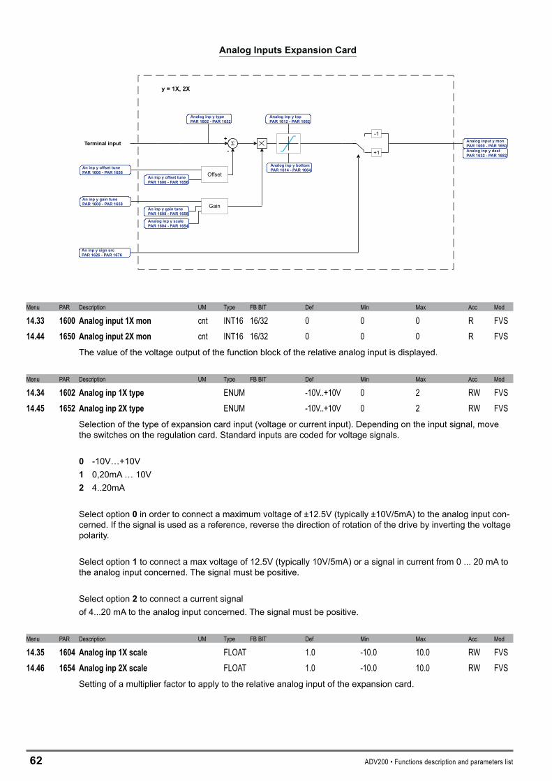
6� ADV200 • Functions description and parameters list
+
- +1
-1
y = 1X, 2X
Offset
Gain
Analog Inputs Expansion Card
Terminal input
Analog inp y typePAR 1602 - PAR 1652
An inp y offset tunePAR 1606 - PAR 1656
An inp y offset tunePAR 1606 - PAR 1656
An inp y gain tunePAR 1608 - PAR 1658
An tunePAR 1608 - PAR 1658
inp y gain
Analog inp y scalePAR 1604 - PAR 1654
Analog inp y bottomPAR 1614 - PAR 1664
Analog inp y topPAR 1612 - PAR 1662
Analog input y monPAR 1600 - PAR 1650Analog inp y destPAR 1632 - PAR 1682
An inp y sign srcPAR 1626 - PAR 1676
Menu PAR Description UM Type FB BIT Def Min Max Acc Mod
14.33 1600 Analoginput1Xmon cnt INT16 16/32 0 0 0 R FVS14.44 1650 Analoginput2Xmon cnt INT16 16/32 0 0 0 R FVS
The value of the voltage output of the function block of the relative analog input is displayed.
Menu PAR Description UM Type FB BIT Def Min Max Acc Mod
14.34 1602 Analoginp1Xtype ENUM -10V..+10V 0 2 RW FVS14.45 1652 Analoginp2Xtype ENUM -10V..+10V 0 2 RW FVS
Selection of the type of expansion card input (voltage or current input). Depending on the input signal, move the switches on the regulation card. Standard inputs are coded for voltage signals.
0 -10V…+10V 1 0,20mA … 10V � 4..20mA
Select option 0 in order to connect a maximum voltage of ±12.5V (typically ±10V/5mA) to the analog input con-cerned. If the signal is used as a reference, reverse the direction of rotation of the drive by inverting the voltage polarity.
Select option 1 to connect a max voltage of 12.5V (typically 10V/5mA) or a signal in current from 0 ... 20 mA to the analog input concerned. The signal must be positive.
Select option � to connect a current signal of 4...20 mA to the analog input concerned. The signal must be positive.
Menu PAR Description UM Type FB BIT Def Min Max Acc Mod
14.35 1604 Analoginp1Xscale FLOAT 1.0 -10.0 10.0 RW FVS14.46 1654 Analoginp2Xscale FLOAT 1.0 -10.0 10.0 RW FVS
Setting of a multiplier factor to apply to the relative analog input of the expansion card.

ADV200 • Functions description and parameters list 6�
1
2 1
2
Analog inp xX scale = 1,0
Analog inp xX scale = 2,0
0 10V
100%
50%
5V
Speed
Example:
The speed reference of a drive is assigned with a max external voltage of 5V. Withthis value the drive must reach the maximum speed allowed (set using Fullscalespeed).As the AnaloginpXscaleparameter the scale factor of 2 is entered (10V : 5V)
Menu PAR Description UM Type FB BIT Def Min Max Acc Mod
14.36 1606 Aninp1Xoffsettune BIT 0 0 1 RWZ FVS14.47 1656 Aninp2Xoffsettune BIT 0 0 1 RWZ FVS
Self-tuning command for the offset of the relative analog input of the expansion card. Automatic fine tuning of the input. To perform self-tuning, set the input signal to its minimum value and execute the command. The conditions containing an offset can be compensated. When this command is sent, AninpxXoffsettuneis automatically selected so that the available input signal corresponds to the zero value of the variable.Automatic tuning can only be performed if the following condition is present:
- Input voltage less than 1V or input current less than 2 mA
Note ! The value that is obtained automatically can be changed manually, if necessary, using AninpoffsetxX.
If the voltage setting on the analog input is higher than 1V, the Value too low alarm is generated.
Menu PAR Description UM Type FB BIT Def Min Max Acc Mod
14.37 1608 Targuadingan1X BIT 0 0 1 RWZ FVS14.48 1658 Targuadingan2X BIT 0 0 1 RWZ FVS
Self-tuning command for the relative analog input gain. Automatic fine tuning of the input. When this command is sent, Analoginp1gainx is automatically selected so that the available input signal corresponds to the maximum value of the variable.Two conditions are necessary in order to perform automatic tuning:
- Input voltage greater than 1V or input current greater than 2 mA- Positive polarity. The value that is found is automatically accepted forthe other direction of rotation.
Note ! If necessary, the value obtained automatically can be changed manually via AnaloginpXxgain.
To perform self-tuning, set the input signal to its maximum value and execute the command. A multiplier factor is calculated to apply to the input signal value (not considering the Analoginpscaleparameter) to reach the full scale value.
If the voltage setting on the analog input is less than 1V, the Value too low alarm is generated.

64 ADV200 • Functions description and parameters list
Menu PAR Description UM Type FB BIT Def Min Max Acc Mod
14.38 1612 Analoginp1Xtop cnt INT16 16384 -32768 32767 ERW FVS14.49 1662 Analoginp2Xtop cnt INT16 16384 -32768 32767 ERW FVS
Setting of the upper speed reference limit as a function of the voltage (or current) of the relative analog refer-ence of the expansion card.
Menu PAR Description UM Type FB BIT Def Min Max Acc Mod
14.39 1614 Analoginp1Xbottom cnt INT16 -16384 -32768 32767 ERW FVS14.50 1664 Analoginp2Xbottom cnt INT16 -16384 -32768 32767 ERW FVS
Setting of the lower speed reference limit as a function of the voltage (or current) of the relative analog refer-ence of the expansion card.
Menu PAR Description UM Type FB BIT Def Min Max Acc Mod
14.40 1616 Analoginp1Xoffset cnt INT16 0 -32768 32767 ERW FVS14.51 1666 Analoginp2Xoffset cnt INT16 0 -32768 32767 ERW FVS
Setting of an offset value to algebrically add to the relative analog input of the expansion card.
0 10V
100%
Analog inp xX offset {
Menu PAR Description UM Type FB BIT Def Min Max Acc Mod
14.41 1618 Analoginp1Xgain FLOAT 1.0 -10.0 10.0 ERW FVS14.52 1668 Analoginp2Xgain FLOAT 1.0 -10.0 10.0 ERW FVS
This parameter contains the value of the multiplier factor to apply to the analog reference of the expansion card calculated using the Analoginpgaintunefunction.
Example:
An external analog reference only reaches a maximum of 9.8V instead of 10V. 1.020 (10V : 9.8V) is entered as the Analoginpxgain parameter.
The same result can be achieved using the Analoginpxgaintune function. This parameter can be selected from the keypad menu. The maximum analog value available (in this case 9.8V) must be present on the termi-nal, with positive polarity. Press the Enter key on the keypad to start analog reference self-tuning.
Menu PAR Description UM Type FB BIT Def Min Max Acc Mod
14.42 1626 Aninp1Xsignsrc LINK 16 6000 0 16384 ERW FVS14.53 1676 Aninp2Xsignsrc LINK 16 6000 0 16384 ERW FVS
Selection of the origin (source) of the signal to be assigned to the relative digital input of the expansion card for selecting the direction of rotation of the motor. The functions that can be associated with the digital outputs are listed in the “L_DIGSEL�” selection list.
ADV200 • Functions description and parameters list 65
Menu PAR Description UM Type FB BIT Def Min Max Acc Mod
14.43 1632 Analoginp1Xdest ILINK 0 0 0 ER FVS14.54 1682 Analoginp2Xdest ILINK 0 0 0 ER FVS
The function for which the relative analog input of the expansion card has been programmed and on which it acts is displayed.
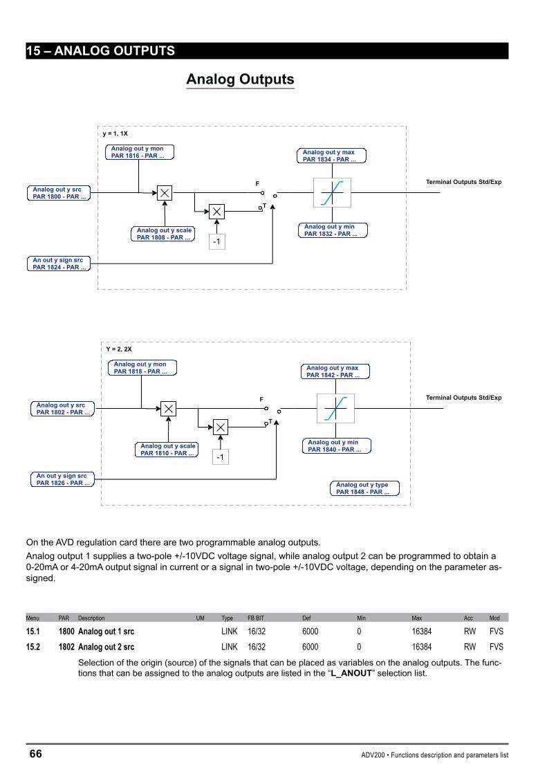
66 ADV200 • Functions description and parameters list
15–ANALOGOUTPUTS
-1
F
T
Y = 2, 2X
-1
F
T
y = 1, 1X
Analog Outputs
Analog out y srcPAR 1802 - PAR ...
Analog out y scalePAR 1810 - PAR ...
An out y sign srcPAR 1826 - PAR ...
Analog out y minPAR 1840 - PAR ...
Analog out y maxPAR 1842 - PAR ...
Analog out y typePAR 1848 - PAR ...
Analog out y srcPAR 1800 - PAR ...
Analog out y scalePAR 1808 - PAR ...
An out y sign srcPAR 1824 - PAR ...
Analog out y minPAR 1832 - PAR ...
Analog out y maxPAR 1834 - PAR ...
Analog out y monPAR 1816 - PAR ...
Analog out y monPAR 1818 - PAR ...
Terminal Outputs Std/Exp
Terminal Outputs Std/Exp
On the AVD regulation card there are two programmable analog outputs.Analog output 1 supplies a two-pole +/-10VDC voltage signal, while analog output 2 can be programmed to obtain a 0-20mA or 4-20mA output signal in current or a signal in two-pole +/-10VDC voltage, depending on the parameter as-signed.
Menu PAR Description UM Type FB BIT Def Min Max Acc Mod
15.1 1800 Analogout1src LINK 16/32 6000 0 16384 RW FVS15.2 1802 Analogout2src LINK 16/32 6000 0 16384 RW FVS
Selection of the origin (source) of the signals that can be placed as variables on the analog outputs. The func-tions that can be assigned to the analog outputs are listed in the “L_ANOUT” selection list.
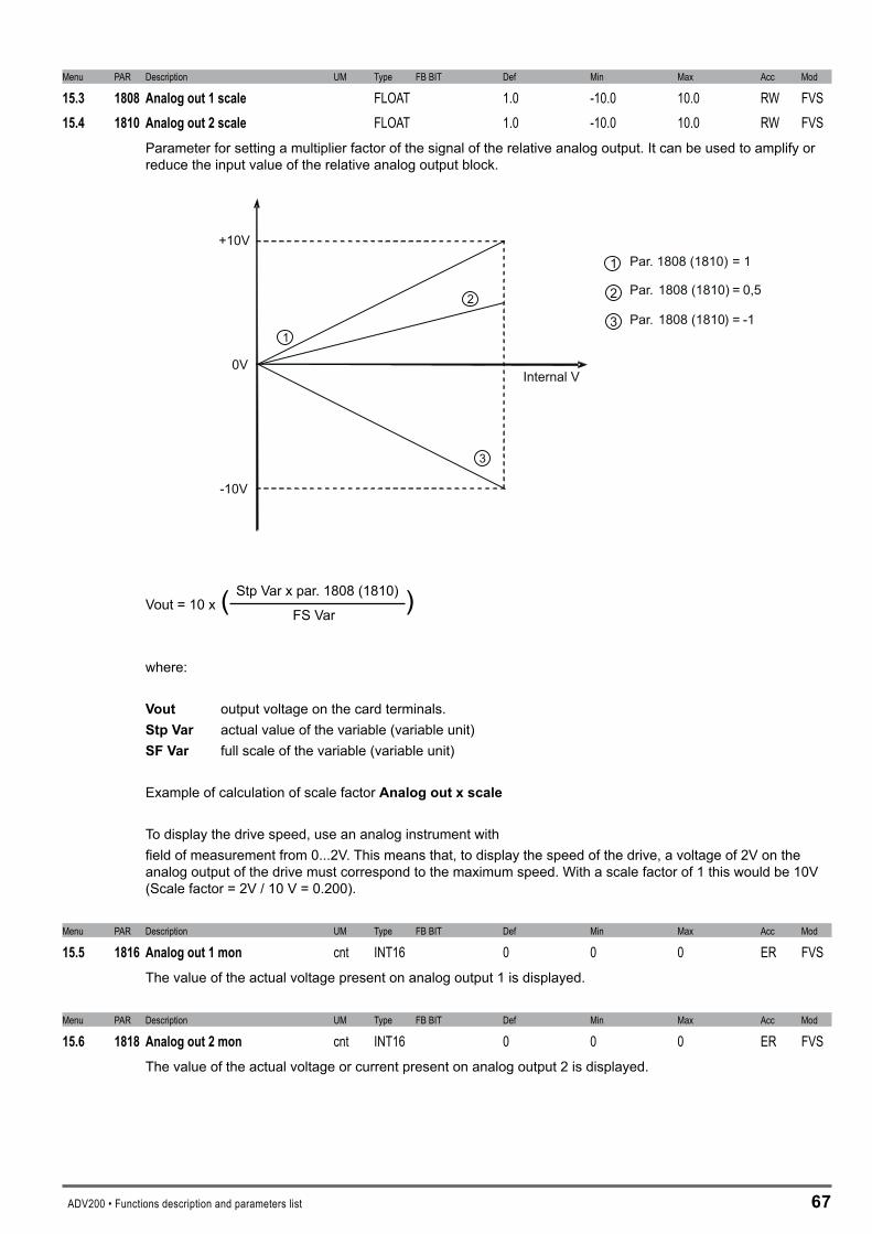
ADV200 • Functions description and parameters list 67
Menu PAR Description UM Type FB BIT Def Min Max Acc Mod
15.3 1808 Analogout1scale FLOAT 1.0 -10.0 10.0 RW FVS15.4 1810 Analogout2scale FLOAT 1.0 -10.0 10.0 RW FVS
Parameter for setting a multiplier factor of the signal of the relative analog output. It can be used to amplify or reduce the input value of the relative analog output block.
1
2
3
+10V
-10V
0VInternal V
1
2
3
Par. 1808 (1810) = 1
Par. 1808 (1810) = 0,5
Par. 1808 (1810) = -1
Stp Var x par. 1808 (1810)
Vout = 10 x ( )
FS Var
where:
Vout output voltage on the card terminals.StpVar actual value of the variable (variable unit)SFVar full scale of the variable (variable unit)
Example of calculation of scale factor Analogoutxscale
To display the drive speed, use an analog instrument withfield of measurement from 0...2V. This means that, to display the speed of the drive, a voltage of 2V on the analog output of the drive must correspond to the maximum speed. With a scale factor of 1 this would be 10V (Scale factor = 2V / 10 V = 0.200).
Menu PAR Description UM Type FB BIT Def Min Max Acc Mod
15.5 1816 Analogout1mon cnt INT16 0 0 0 ER FVSThe value of the actual voltage present on analog output 1 is displayed.
Menu PAR Description UM Type FB BIT Def Min Max Acc Mod
15.6 1818 Analogout2mon cnt INT16 0 0 0 ER FVSThe value of the actual voltage or current present on analog output 2 is displayed.

6� ADV200 • Functions description and parameters list
Menu PAR Description UM Type FB BIT Def Min Max Acc Mod
15.7 1824 Anout1signsrc LINK 16 6000 0 16384 ERW FVS15.8 1826 Anout2signsrc LINK 16 6000 0 16384 ERW FVS
Selection of the origin (source) for the signal that determines the sign of the relative analog output. The terminal to be associated with this function can be selected from the “L_DIGSEL�” selection list.
Menu PAR Description UM Type FB BIT Def Min Max Acc Mod
15.9 1832 Analogout1min cnt INT16 -16384 -32768 32767 ERW FVS15.10 1834 Analogout1max cnt INT16 16384 -32768 32767 ERW FVS
Setting of the minimum and maximum values for the analog output for the voltage present on analog output 1
Menu PAR Description UM Type FB BIT Def Min Max Acc Mod
15.11 1840 Analogout2min cnt INT16 -16384 -32768 32767 ERW FVS15.12 1842 Analogout2max cnt INT16 16384 -32768 32767 ERW FVS
Setting of the minimum and maximum values for the analog output for the voltage present on analog output 2
Menu PAR Description UM Type FB BIT Def Min Max Acc Mod
15.13 1848 Analogout2type ENUM -10V..+10V 0 2 ERW FVSSelection of the type of output (in voltage or current). Depending on the output signal, move the switch on the regulation card. The standard output is coded for the signal in voltage.
0 -10V..+10V 1 0,20mA … 10V � 4..20mA Select option 0 in order to apply a maximum voltage of ±12.5V (typically ±10V/5mA) to analog output 2.
Select option 1 in order to apply a maximum voltage of +10V or a signal in current of 0 ... 20 mA to analog output 2. The signal must be positive.
Select option � to apply a signal in current of 4...20 mA to analog output 2.
Menu PAR Description UM Type FB BIT Def Min Max Acc Mod
15.14 1850 Analogout1Xsrc LINK 16/32 6000 0 16384 RW FVS15.15 1852 Analogout2Xsrc LINK 16/32 6000 0 16384 RW FVS
Selection of the origin (source) of the signals that can be placed as variables on the analog outputs of the ex-pansion card. The functions that can be assigned to the analog outputs are listed in the “L_ANOUT” selection list.
Menu PAR Description UM Type FB BIT Def Min Max Acc Mod
15.16 1858 Analogout1Xscale FLOAT 1.0 -10.0 10.0 RW FVS15.17 1860 Analogout2Xscale FLOAT 1.0 -10.0 10.0 RW FVS
Parameter for setting a multiplier factor of the signal of the relative analog output of the expansion card. It can be used to amplify or reduce the input value of the relative analog output block.
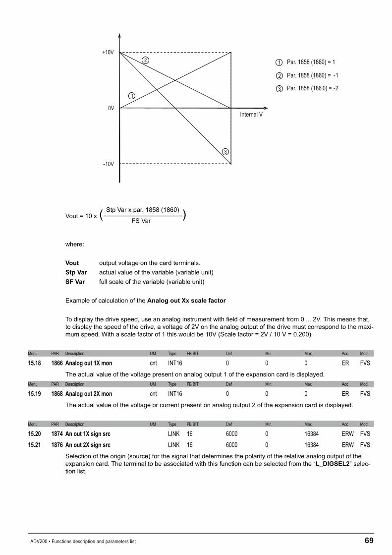
ADV200 • Functions description and parameters list 69
1
2
3
+10V
-10V
0VInternal V
1
2
3
Par. 1858 (1860) = 1
Par. 1858 (1860) = -1
Par. 1858 (186 0) = -2
Stp Var x par. 1858 (1860)
Vout = 10 x ( )
FS Var
where:
Vout output voltage on the card terminals.StpVar actual value of the variable (variable unit)SFVar full scale of the variable (variable unit)
Example of calculation of the AnalogoutXxscalefactor
To display the drive speed, use an analog instrument with field of measurement from 0 ... 2V. This means that, to display the speed of the drive, a voltage of 2V on the analog output of the drive must correspond to the maxi-mum speed. With a scale factor of 1 this would be 10V (Scale factor = 2V / 10 V = 0.200).
Menu PAR Description UM Type FB BIT Def Min Max Acc Mod
15.18 1866 Analogout1Xmon cnt INT16 0 0 0 ER FVSThe actual value of the voltage present on analog output 1 of the expansion card is displayed.
Menu PAR Description UM Type FB BIT Def Min Max Acc Mod
15.19 1868 Analogout2Xmon cnt INT16 0 0 0 ER FVSThe actual value of the voltage or current present on analog output 2 of the expansion card is displayed.
Menu PAR Description UM Type FB BIT Def Min Max Acc Mod
15.20 1874 Anout1Xsignsrc LINK 16 6000 0 16384 ERW FVS15.21 1876 Anout2Xsignsrc LINK 16 6000 0 16384 ERW FVS
Selection of the origin (source) for the signal that determines the polarity of the relative analog output of the expansion card. The terminal to be associated with this function can be selected from the “L_DIGSEL�” selec-tion list.
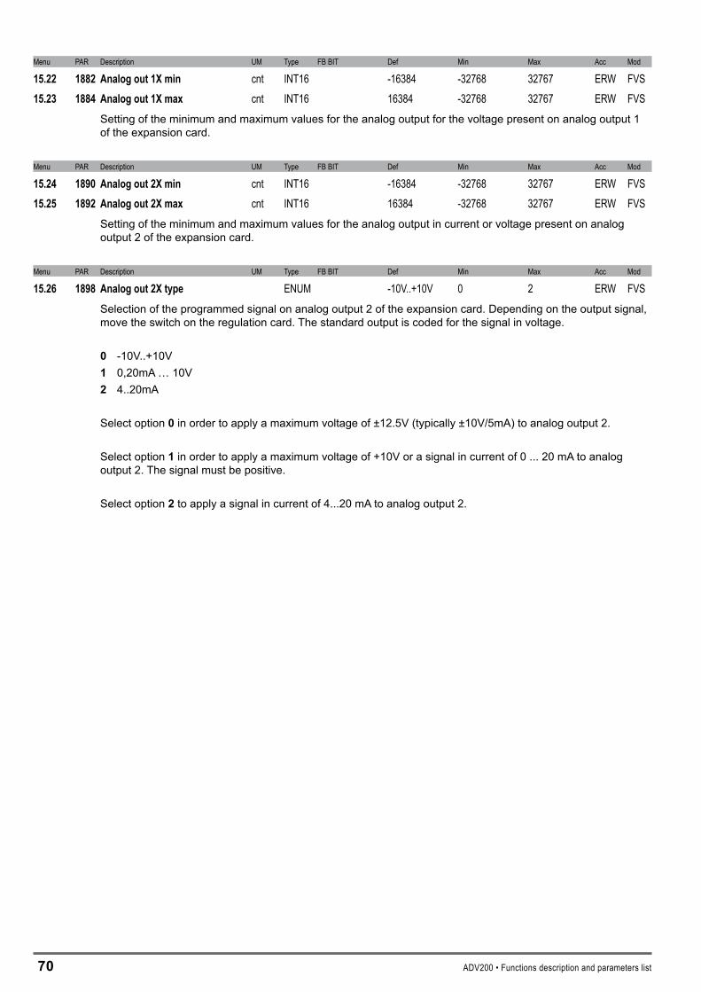
70 ADV200 • Functions description and parameters list
Menu PAR Description UM Type FB BIT Def Min Max Acc Mod
15.22 1882 Analogout1Xmin cnt INT16 -16384 -32768 32767 ERW FVS15.23 1884 Analogout1Xmax cnt INT16 16384 -32768 32767 ERW FVS
Setting of the minimum and maximum values for the analog output for the voltage present on analog output 1 of the expansion card.
Menu PAR Description UM Type FB BIT Def Min Max Acc Mod
15.24 1890 Analogout2Xmin cnt INT16 -16384 -32768 32767 ERW FVS15.25 1892 Analogout2Xmax cnt INT16 16384 -32768 32767 ERW FVS
Setting of the minimum and maximum values for the analog output in current or voltage present on analog output 2 of the expansion card.
Menu PAR Description UM Type FB BIT Def Min Max Acc Mod
15.26 1898 Analogout2Xtype ENUM -10V..+10V 0 2 ERW FVSSelection of the programmed signal on analog output 2 of the expansion card. Depending on the output signal, move the switch on the regulation card. The standard output is coded for the signal in voltage.
0 -10V..+10V 1 0,20mA … 10V � 4..20mA Select option 0 in order to apply a maximum voltage of ±12.5V (typically ±10V/5mA) to analog output 2.
Select option 1 in order to apply a maximum voltage of +10V or a signal in current of 0 ... 20 mA to analog output 2. The signal must be positive.
Select option � to apply a signal in current of 4...20 mA to analog output 2.

ADV200 • Functions description and parameters list 71
16–MOTORDATA
From this menu you can enter the motor plate data and “basic” values for the voltage/frequency characteristics. It is important to enter the correct data in order to optimize drive operation and that of the application as a whole. These data are required in order to obtain:
a) Computation of the normalization factors necessary for regulation b) Computation of the estimated values for the motor parameters necessary for regulation
Rated voltage, Rated speed, Rated frequency, Rated current, Cos phi, Basic voltage and Basic frequency must be en-tered (the Cos phi default value can be used if this value it not present on the plate). After entering these parameters, send a Take motor par command to calculate (a) and (b) above. The motor cannot be enabled until the Take motor par command has been set. If some results are inconsistent, or if the motor is much smaller than the inverter, an error message is displayed indicating a numerical capacity overflow and the previous set of parameters is restored in the “Mot plate data” sub-menu.
P.2006 P.2000 P.2002
P.2012
P.2006 P.2000 P.2002
P.2012
3 kW
Motor: 3 phase
1420 rpm
Motor & Co.Type: ABCDE
400 V
IP54
Made in ..............
6.7 A
IEC 34-1 / VDE 0530
Iso Kl F
Nr. 12345-91
S1
50 Hz
Power factor 0.8I nomRated voltage
Rated power
Rated speed (n )N
2 Hp
Motor: 3 phase
1750 rpm
Motor & Co.Type: ABCDE
575 V
IP54
Made in ..............
2 A
IEC 34-1 / VDE 0530
Iso Kl F
Nr. 12345-91
S1
60 Hz
Power factor 0.83I nomRated voltage
Rated power
Rated speed (n )N Efficiency 86.5
kW and HP motor data plates
Menu PAR Description UM Type FB BIT Def Min Max Acc Mod
16.1 2000 Ratedvoltage V FLOAT SIZE 50.0 690.0 RWZS FVSSet the motor rated voltage as indicated on the data plate. This is the voltage the drive must supplyat the motor rated frequency.
Menu PAR Description UM Type FB BIT Def Min Max Acc Mod
16.2 2002 Ratedcurrent A FLOAT SIZE 1.0 1000.0 RWZS FVSThe motor rated current at its rated power (kW / Hp) and voltage (indicated on the motor data plate).If using a single drive to control several motors connected in parallel (only possible in the V/f mode), enter a value that corresponds to the sum of the rated currents of all the motors; in this case do not perform any self-tuning operations.
Menu PAR Description UM Type FB BIT Def Min Max Acc Mod
16.3 2004 Ratedspeed rpm FLOAT SIZE 10.0 32000.0 RWZS FVSRated speed of the motor with full load in rpm (rpm = m-1). In some motors the synchronous speed (e.g. 1500 rpm for a 4-pole motor) and slippage, i.e. the loss of revolutions between the motor idling condition and the rated load condition (e.g. 80 rpm), is indicated. Enter the following: synchronous speed - slippage.
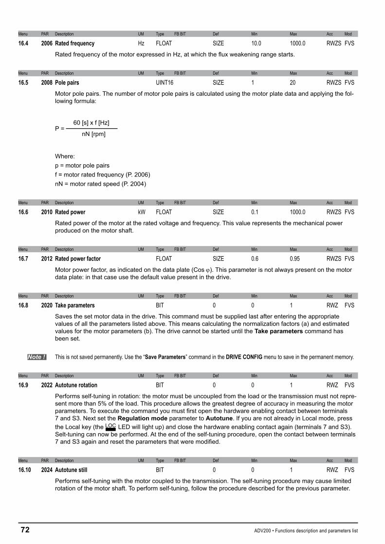
7� ADV200 • Functions description and parameters list
Menu PAR Description UM Type FB BIT Def Min Max Acc Mod
16.4 2006 Ratedfrequency Hz FLOAT SIZE 10.0 1000.0 RWZS FVSRated frequency of the motor expressed in Hz, at which the flux weakening range starts.
Menu PAR Description UM Type FB BIT Def Min Max Acc Mod
16.5 2008 Polepairs UINT16 SIZE 1 20 RWZS FVSMotor pole pairs. The number of motor pole pairs is calculated using the motor plate data and applying the fol-lowing formula:
60 [s] x f [Hz]P = nN [rpm]
Where: p = motor pole pairsf = motor rated frequency (P. 2006)nN = motor rated speed (P. 2004)
Menu PAR Description UM Type FB BIT Def Min Max Acc Mod
16.6 2010 Ratedpower kW FLOAT SIZE 0.1 1000.0 RWZS FVSRated power of the motor at the rated voltage and frequency. This value represents the mechanical power produced on the motor shaft.
Menu PAR Description UM Type FB BIT Def Min Max Acc Mod
16.7 2012 Ratedpowerfactor FLOAT SIZE 0.6 0.95 RWZS FVSMotor power factor, as indicated on the data plate (Cos j). This parameter is not always present on the motor data plate: in that case use the default value present in the drive.
Menu PAR Description UM Type FB BIT Def Min Max Acc Mod
16.8 2020 Takeparameters BIT 0 0 1 RWZ FVSSaves the set motor data in the drive. This command must be supplied last after entering the appropriate values of all the parameters listed above. This means calculating the normalization factors (a) and estimated values for the motor parameters (b). The drive cannot be started until the Takeparameterscommand has been set.
Note ! This is not saved permanently. Use the “SaveParameters” command in the DRIVECONFIGmenu to save in the permanent memory.
Menu PAR Description UM Type FB BIT Def Min Max Acc Mod
16.9 2022 Autotunerotation BIT 0 0 1 RWZ FVSPerforms self-tuning in rotation: the motor must be uncoupled from the load or the transmission must not repre-sent more than 5% of the load. This procedure allows the greatest degree of accuracy in measuring the motor parameters. To execute the command you must first open the hardware enabling contact between terminals 7 and S3. Next set the Regulationmodeparameter to Autotune. If you are not already in Local mode, press the Local key (the LOC LED will light up) and close the hardware enabling contact again (terminals 7 and S3). Selt-tuning can now be performed. At the end of the self-tuning procedure, open the contact between terminals 7 and S3 again and reset the parameters that were modified.
Menu PAR Description UM Type FB BIT Def Min Max Acc Mod
16.10 2024 Autotunestill BIT 0 0 1 RWZ FVSPerforms self-tuning with the motor coupled to the transmission. The self-tuning procedure may cause limited rotation of the motor shaft. To perform self-tuning, follow the procedure described for the previous parameter.
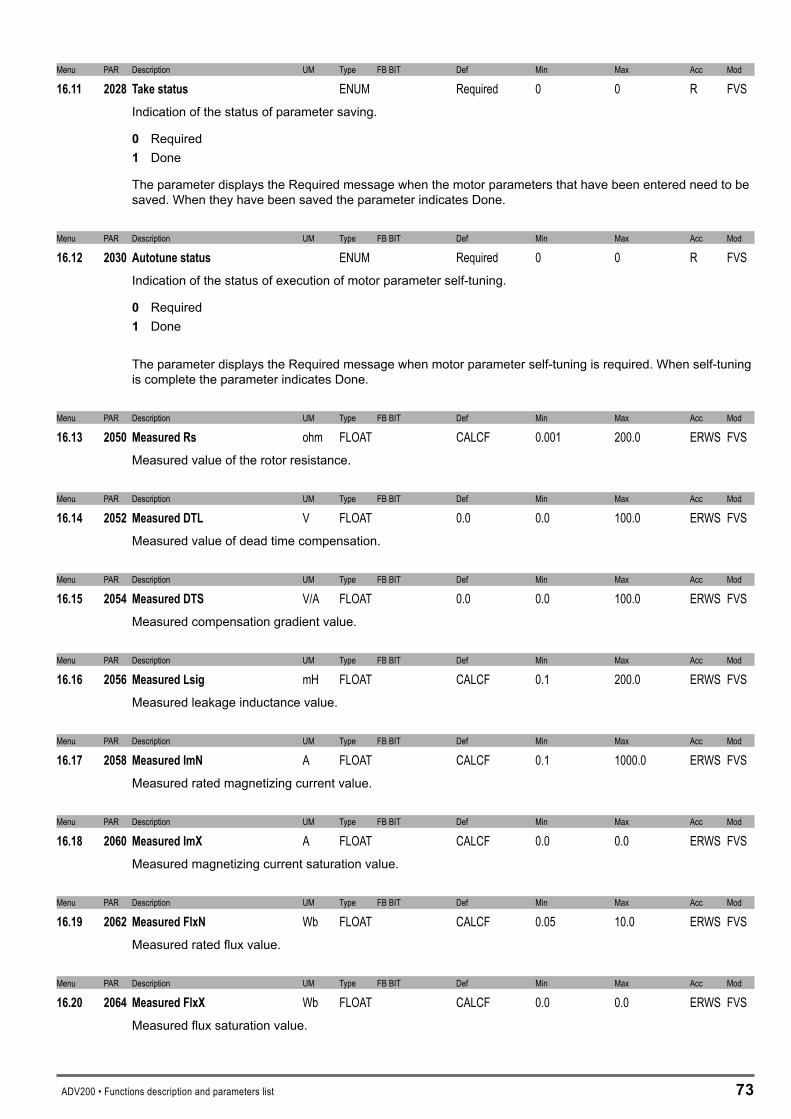
ADV200 • Functions description and parameters list 7�
Menu PAR Description UM Type FB BIT Def Min Max Acc Mod
16.11 2028 Takestatus ENUM Required 0 0 R FVSIndication of the status of parameter saving.
0 Required 1 Done
The parameter displays the Required message when the motor parameters that have been entered need to be saved. When they have been saved the parameter indicates Done.
Menu PAR Description UM Type FB BIT Def Min Max Acc Mod
16.12 2030 Autotunestatus ENUM Required 0 0 R FVSIndication of the status of execution of motor parameter self-tuning.
0 Required 1 Done
The parameter displays the Required message when motor parameter self-tuning is required. When self-tuning is complete the parameter indicates Done.
Menu PAR Description UM Type FB BIT Def Min Max Acc Mod
16.13 2050 MeasuredRs ohm FLOAT CALCF 0.001 200.0 ERWS FVSMeasured value of the rotor resistance.
Menu PAR Description UM Type FB BIT Def Min Max Acc Mod
16.14 2052 MeasuredDTL V FLOAT 0.0 0.0 100.0 ERWS FVSMeasured value of dead time compensation.
Menu PAR Description UM Type FB BIT Def Min Max Acc Mod
16.15 2054 MeasuredDTS V/A FLOAT 0.0 0.0 100.0 ERWS FVSMeasured compensation gradient value.
Menu PAR Description UM Type FB BIT Def Min Max Acc Mod
16.16 2056 MeasuredLsig mH FLOAT CALCF 0.1 200.0 ERWS FVSMeasured leakage inductance value.
Menu PAR Description UM Type FB BIT Def Min Max Acc Mod
16.17 2058 MeasuredImN A FLOAT CALCF 0.1 1000.0 ERWS FVSMeasured rated magnetizing current value.
Menu PAR Description UM Type FB BIT Def Min Max Acc Mod
16.18 2060 MeasuredImX A FLOAT CALCF 0.0 0.0 ERWS FVSMeasured magnetizing current saturation value.
Menu PAR Description UM Type FB BIT Def Min Max Acc Mod
16.19 2062 MeasuredFlxN Wb FLOAT CALCF 0.05 10.0 ERWS FVSMeasured rated flux value.
Menu PAR Description UM Type FB BIT Def Min Max Acc Mod
16.20 2064 MeasuredFlxX Wb FLOAT CALCF 0.0 0.0 ERWS FVSMeasured flux saturation value.
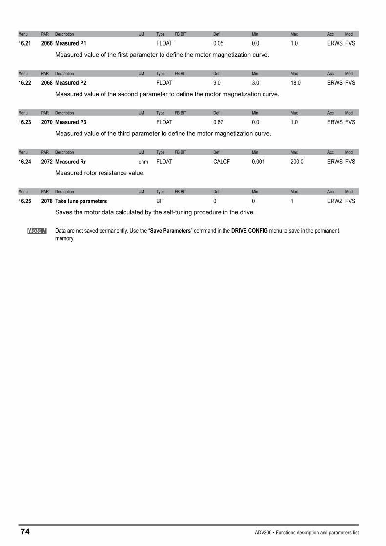
74 ADV200 • Functions description and parameters list
Menu PAR Description UM Type FB BIT Def Min Max Acc Mod
16.21 2066 MeasuredP1 FLOAT 0.05 0.0 1.0 ERWS FVSMeasured value of the first parameter to define the motor magnetization curve.
Menu PAR Description UM Type FB BIT Def Min Max Acc Mod
16.22 2068 MeasuredP2 FLOAT 9.0 3.0 18.0 ERWS FVSMeasured value of the second parameter to define the motor magnetization curve.
Menu PAR Description UM Type FB BIT Def Min Max Acc Mod
16.23 2070 MeasuredP3 FLOAT 0.87 0.0 1.0 ERWS FVSMeasured value of the third parameter to define the motor magnetization curve.
Menu PAR Description UM Type FB BIT Def Min Max Acc Mod
16.24 2072 MeasuredRr ohm FLOAT CALCF 0.001 200.0 ERWS FVSMeasured rotor resistance value.
Menu PAR Description UM Type FB BIT Def Min Max Acc Mod
16.25 2078 Taketuneparameters BIT 0 0 1 ERWZ FVSSaves the motor data calculated by the self-tuning procedure in the drive.
Note ! Data are not saved permanently. Use the “SaveParameters” command in the DRIVECONFIGmenu to save in the permanent memory.

ADV200 • Functions description and parameters list 75
17–ENCODERCONFIG
The closed-loop control mode requires a speed reading by a digital encoder on the motor shaft. The optional EXP-ENC card is necessary in order to acquire the encoder signals. The natural variation in speed generated by machine load induction, known as slippage, can be compensated by the speed feedback supplied by the encoder in V/f mode. In the field oriented vector mode, closed-loop encoder feedback is essential for correct drive operation.
Menu PAR Description UM Type FB BIT Def Min Max Acc Mod
17.1 2100 Encoderpulses ppr UINT16 1024 128 16384 RWZ FVSSetting of the number of feedback encoder impulses.
Menu PAR Description UM Type FB BIT Def Min Max Acc Mod
17.2 2130 Encoderdirection ENUM Not inverted 0 1 RWZ FVSSelection of the encoder direction
0 Not inverted 1 Inverted
By setting 0 the encoder feedback signals are not inverted.
By setting 1 the encoder feedback signals are inverted.
Menu PAR Description UM Type FB BIT Def Min Max Acc Mod
17.3 2132 Encodermode ENUM None 0 3 ERWZ FVSSetting of the method for measuring the speed of the digital encoder connected to the optional card.
0 None 1 Digital FP � Digital F � Sinus 4 Sinus SINCOS 5 Sinus ENDAT 6 Sinus SSI 7 Sinus HIPER� Resolver
When set to 1 the frequency and period measurement method is selected. With this method you can obtain a high level of accuracy and dynamic values at medium and high speeds. When set to � the frequency measurement method is selected. This selection is recommended for applications that require operation at very low motor speeds.
Settings � to � are currently being developed.
Menu PAR Description UM Type FB BIT Def Min Max Acc Mod
17.4 2134 Encoderspeedfilter ms FLOAT 2.0 0.1 20.0 ERW FVSSetting of the time constant of the filter applied to the feedback encoder pulse reading. The parameter affects both the accuracy of the speed measurement and the dynamics obtainable in closed loop control. Long updat-ing times allow greater stability (more filtering) of the speed measurement, as a higher number of encoder pulses are counted at a given speed of rotation. On the other hand, the use of a speed measurement filter introduces delays that do not permit high control loop dynamics. Low settings extend the regulation bandwidth but may accentuate any disturbance.

76 ADV200 • Functions description and parameters list
Menu PAR Description UM Type FB BIT Def Min Max Acc Mod
17.5 2150 Encoderspeed rpm INT16 16/32 0 0 0 ER FVSThe motor speed measured by the encoder is displayed.
Menu PAR Description UM Type FB BIT Def Min Max Acc Mod
17.6 2162 Encoderposition cnt UINT16 16 0 0 0 ER FVSThe encoder position is displayed. The scale is Number of encoder impulses *4.

ADV200 • Functions description and parameters list 77
1�–SPEEDREGGAINS
Ref
Ref
Gain adapt
Speed reg P1 gainPAR 2002
Speed reg I2 timePAR 2206
Speed reg I1 timePAR 2202
Speed reg P2 gainPAR 2204
Gain adapt spd band1 2PAR 2220
Gain adapt spd thr1 2PAR 2218
Gain adapt srcPAR 2216
Spd reg I time InusePAR 2234
Spd reg P gain InusePAR 2232
Speed reg P0 gainPAR 2228
Speed reg I0 timePAR 2230
Gain 0 enablePAR 2226
The speed adaptive allows different speed regulator gains to be obtained according to the speed or another value. The behaviour of the speed regulator can thus be configured in the best way for the specific application requirements.
Note ! Current, flux and voltage regulators can be set using the self-tuning procedure. If this is not successful, current and flux regulators can be tuned manually (this does not apply to voltage regulators, whch must not be modified by the user). The speed regulator must be tuned manually. Gains are usually adjusted according to the drive speed.
Menu PAR Description UM Type FB BIT Def Min Max Acc Mod
18.1 2200 SpeedregP1gain perc INT16 100 0 1000 RW F_S18.2 2202 SpeedregI1time perc INT16 100 0 1000 RW F_S
Setting of the proportional and integral gain of the speed regulator, set 1.
Menu PAR Description UM Type FB BIT Def Min Max Acc Mod
18.3 2204 SpeedregP2gain perc INT16 100 0 1000 ERW F_S18.4 2206 SpeedregI2time perc INT16 100 0 1000 ERW F_S
Setting of the proportional and integral gain of the speed regulator, set 2.
Menu PAR Description UM Type FB BIT Def Min Max Acc Mod
18.5 2216 Gainadaptsrc LINK 16/32 664 0 16384 ERW F_SSelection of the origin (source) of the signal to be used for the adaptive speed gain. The values that can be as-sociated with the function are listed in the “L_REF” selection list.
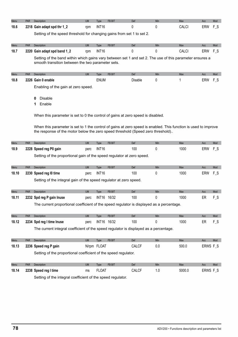
7� ADV200 • Functions description and parameters list
Menu PAR Description UM Type FB BIT Def Min Max Acc Mod
18.6 2218 Gainadaptspdthr1_2 rpm INT16 0 0 CALCI ERW F_SSetting of the speed threshold for changing gains from set 1 to set 2.
Menu PAR Description UM Type FB BIT Def Min Max Acc Mod
18.7 2220 Gainadaptspdband1_2 rpm INT16 0 0 CALCI ERW F_SSetting of the band within which gains vary between set 1 and set 2. The use of this parameter ensures a smooth transition between the two parameter sets.
Menu PAR Description UM Type FB BIT Def Min Max Acc Mod
18.8 2226 Gain0enable ENUM Disable 0 1 ERW F_SEnabling of the gain at zero speed.
0 Disable 1 Enable
When this parameter is set to 0 the control of gains at zero speed is disabled.
When this parameter is set to 1 the control of gains at zero speed is enabled. This function is used to improve the response of the motor below the zero speed threshold (Speed zero threshold)..
Menu PAR Description UM Type FB BIT Def Min Max Acc Mod
18.9 2228 SpeedregP0gain perc INT16 100 0 1000 ERW F_SSetting of the proportional gain of the speed regulator at zero speed.
Menu PAR Description UM Type FB BIT Def Min Max Acc Mod
18.10 2230 SpeedregI0time perc INT16 100 0 1000 ERW F_SSetting of the integral gain of the speed regulator at zero speed.
Menu PAR Description UM Type FB BIT Def Min Max Acc Mod
18.11 2232 SpdregPgainInuse perc INT16 16/32 100 0 1000 ER F_SThe current proportional coefficient of the speed regulator is displayed as a percentage.
Menu PAR Description UM Type FB BIT Def Min Max Acc Mod
18.12 2234 SpdregItimeInuse perc INT16 16/32 100 0 1000 ER F_SThe current integral coefficient of the speed regulator is displayed as a percentage.
Menu PAR Description UM Type FB BIT Def Min Max Acc Mod
18.13 2236 SpeedregPgain N/rpm FLOAT CALCF 0.0 500.0 ERWS F_SSetting of the proportional coefficient of the speed regulator.
Menu PAR Description UM Type FB BIT Def Min Max Acc Mod
18.14 2238 SpeedregItime ms FLOAT CALCF 1.0 5000.0 ERWS F_SSetting of the integral coefficient of the speed regulator.
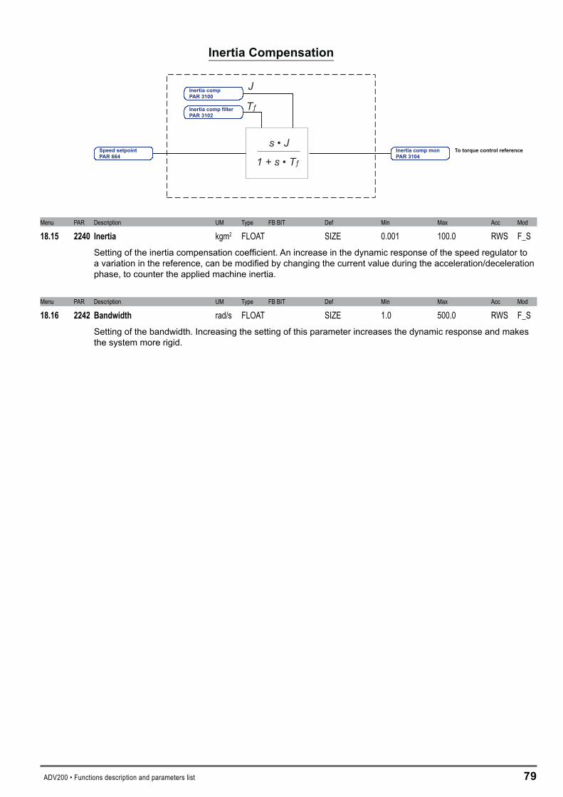
ADV200 • Functions description and parameters list 79
To torque control references • J
1 + s • Tƒ
Tƒ
J
Inertia Compensation
Inertia comp filterPAR 3102
Inertia compPAR 3100
Inertia comp monPAR 3104
Speed setpointPAR 664
Menu PAR Description UM Type FB BIT Def Min Max Acc Mod
18.15 2240 Inertia kgm2 FLOAT SIZE 0.001 100.0 RWS F_SSetting of the inertia compensation coefficient. An increase in the dynamic response of the speed regulator to a variation in the reference, can be modified by changing the current value during the acceleration/deceleration phase, to counter the applied machine inertia.
Menu PAR Description UM Type FB BIT Def Min Max Acc Mod
18.16 2242 Bandwidth rad/s FLOAT SIZE 1.0 500.0 RWS F_SSetting of the bandwidth. Increasing the setting of this parameter increases the dynamic response and makes the system more rigid.

�0 ADV200 • Functions description and parameters list
19–REGULATORPARAM
T
Speed PI regulator
+
+
Torque current limit
To currentcontrol0 F
+
-
From inertia compensation
Torque control - flux vector CL/OL
Speed reg P gainPAR 2236
Speed reg I timePAR 2238
Torque ref 1 srcPAR 2382Dig torque ref 1PAR 2380
Control mode selectPAR 556
Torque curr lim srcPAR 2358
Torque curr lim PosPAR 2350
Torque curr lim NegPAR 2352
Torque curr lim selPAR 2354
Torque lim Pos InusePAR 2360
Torque lim Neg InusePAR 2362
Start/Stop
From Gain adapt
Speed setpointPAR 664
Measured speed
Menu PAR Description UM Type FB BIT Def Min Max Acc Mod
19.1 2250 CurrentregPgain V/A FLOAT CALCF 0.0 0.0 ERWS F_SSetting of the proportional coefficient of the current regulator.
Menu PAR Description UM Type FB BIT Def Min Max Acc Mod
19.2 2252 CurrentregItime ms FLOAT CALCF 0.0 0.0 ERWS F_SSetting of the integral coefficient of the current regulator.
Menu PAR Description UM Type FB BIT Def Min Max Acc Mod
19.3 2260 FluxregPgain A/Wb FLOAT CALCF 0.0 0.0 ERWS F__Setting of the proportional coefficient of the flux regulator.
Menu PAR Description UM Type FB BIT Def Min Max Acc Mod
19.4 2262 FluxregItime ms FLOAT CALCF 0.0 0.0 ERWS F__Setting of the integral coefficient of the flux regulator.
Menu PAR Description UM Type FB BIT Def Min Max Acc Mod
19.5 2264 FluxregPgainOL A/Wb FLOAT CALCF 0.0 0.0 ERWS __SSetting of the flux regulator proportional gain when the drive is used in open loop sensorless vector control mode. This parameter is set automatically by the self-tuning procedure.
Menu PAR Description UM Type FB BIT Def Min Max Acc Mod
19.6 2266 FluxregItimeOL ms FLOAT CALCF 0.0 0.0 ERWS __SSetting of the flux regulator integral time when the drive is used in open loop sensorless vector control mode. This parameter is set automatically by the self-tuning procedure.

ADV200 • Functions description and parameters list �1
Menu PAR Description UM Type FB BIT Def Min Max Acc Mod
19.7 2270 VoltageregPgain Wb/V FLOAT CALCF 0.0 0.0 ERWS F_SSetting of the proportional coefficient of the voltage regulator.
Menu PAR Description UM Type FB BIT Def Min Max Acc Mod
19.8 2272 VoltageregItime s FLOAT CALCF 0.0 0.0 ERWS F_Setting of the integral coefficient of the voltage regulator.
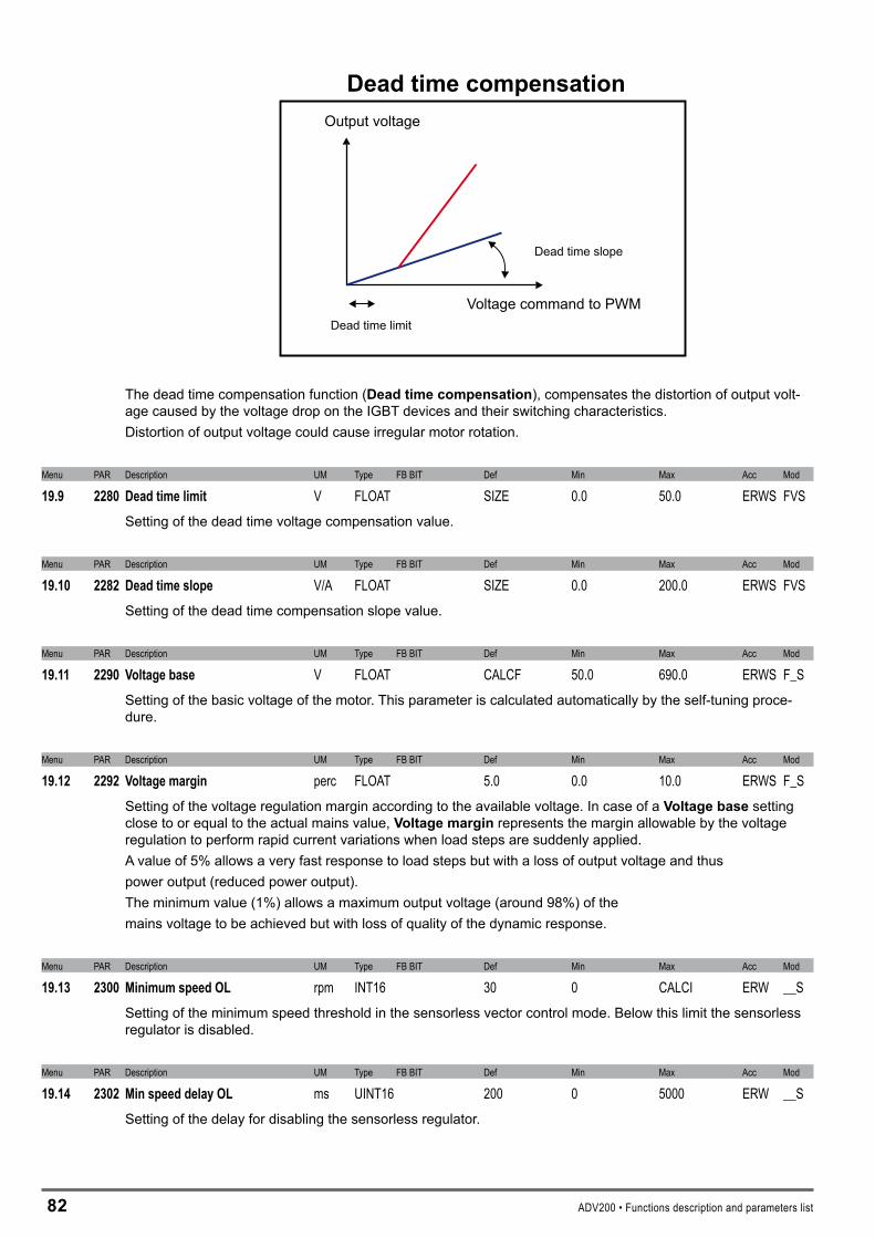
�� ADV200 • Functions description and parameters list
Dead time limit
Dead time slope
Dead time compensationOutput voltage
Voltage command to PWM
The dead time compensation function (Deadtimecompensation), compensates the distortion of output volt-age caused by the voltage drop on the IGBT devices and their switching characteristics.Distortion of output voltage could cause irregular motor rotation.
Menu PAR Description UM Type FB BIT Def Min Max Acc Mod
19.9 2280 Deadtimelimit V FLOAT SIZE 0.0 50.0 ERWS FVSSetting of the dead time voltage compensation value.
Menu PAR Description UM Type FB BIT Def Min Max Acc Mod
19.10 2282 Deadtimeslope V/A FLOAT SIZE 0.0 200.0 ERWS FVSSetting of the dead time compensation slope value.
Menu PAR Description UM Type FB BIT Def Min Max Acc Mod
19.11 2290 Voltagebase V FLOAT CALCF 50.0 690.0 ERWS F_SSetting of the basic voltage of the motor. This parameter is calculated automatically by the self-tuning proce-dure.
Menu PAR Description UM Type FB BIT Def Min Max Acc Mod
19.12 2292 Voltagemargin perc FLOAT 5.0 0.0 10.0 ERWS F_SSetting of the voltage regulation margin according to the available voltage. In case of a Voltagebasesetting close to or equal to the actual mains value, Voltagemarginrepresents the margin allowable by the voltage regulation to perform rapid current variations when load steps are suddenly applied.A value of 5% allows a very fast response to load steps but with a loss of output voltage and thuspower output (reduced power output).The minimum value (1%) allows a maximum output voltage (around 98%) of themains voltage to be achieved but with loss of quality of the dynamic response.
Menu PAR Description UM Type FB BIT Def Min Max Acc Mod
19.13 2300 MinimumspeedOL rpm INT16 30 0 CALCI ERW __SSetting of the minimum speed threshold in the sensorless vector control mode. Below this limit the sensorless regulator is disabled.
Menu PAR Description UM Type FB BIT Def Min Max Acc Mod
19.14 2302 MinspeeddelayOL ms UINT16 200 0 5000 ERW __SSetting of the delay for disabling the sensorless regulator.
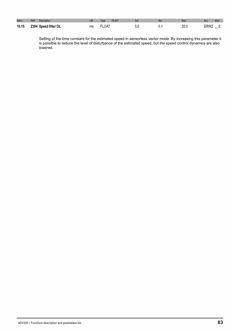
ADV200 • Functions description and parameters list ��
Menu PAR Description UM Type FB BIT Def Min Max Acc Mod
19.15 2304 SpeedfilterOL ms FLOAT 5.0 0.1 20.0 ERWZ __S
Setting of the time constant for the estimated speed in sensorless vector mode. By increasing this parameter it is possible to reduce the level of disturbance of the estimated speed, but the speed control dynamics are also lowered.
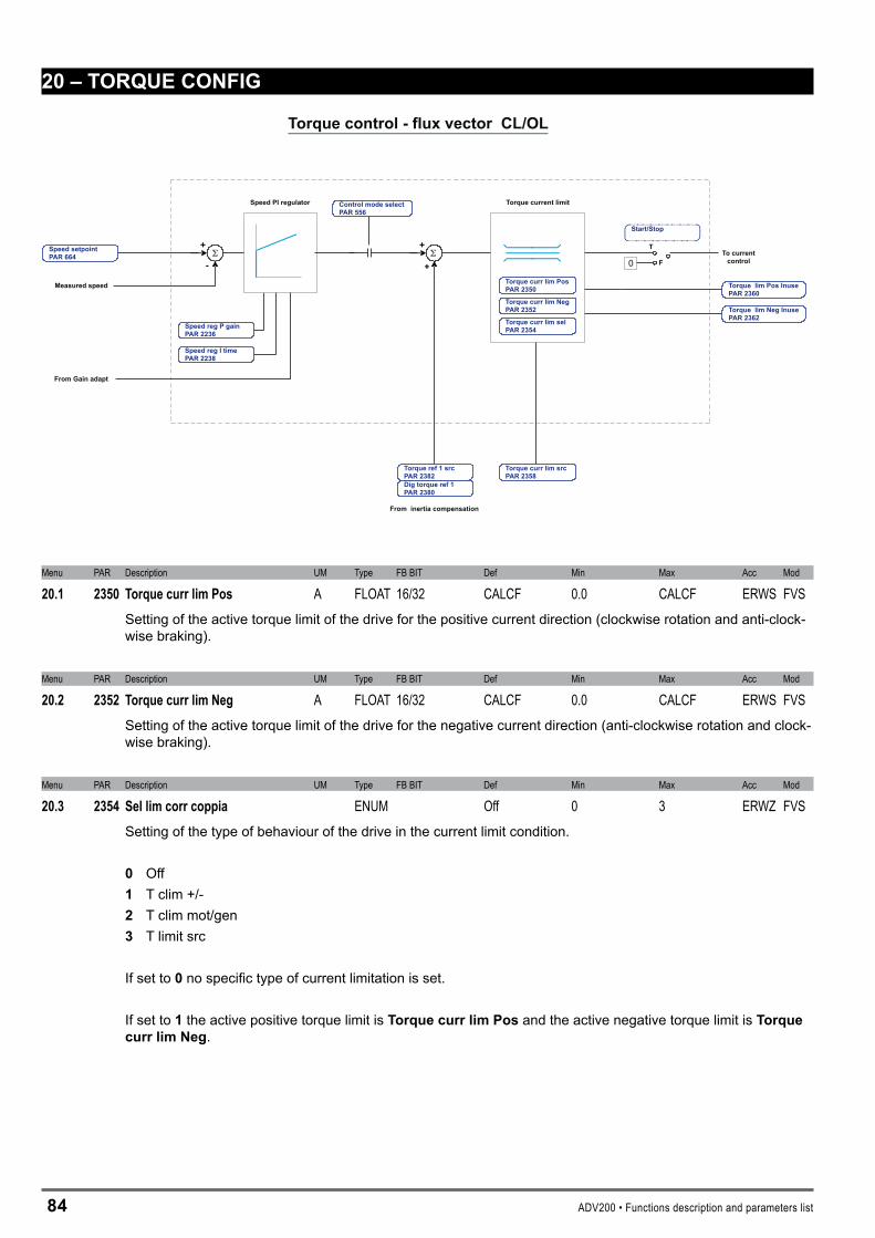
�4 ADV200 • Functions description and parameters list
�0–TORQUECONFIG
T
Speed PI regulator
+
+
Torque current limit
To currentcontrol0 F
+
-
From inertia compensation
Torque control - flux vector CL/OL
Speed reg P gainPAR 2236
Speed reg I timePAR 2238
Torque ref 1 srcPAR 2382Dig torque ref 1PAR 2380
Control mode selectPAR 556
Torque curr lim srcPAR 2358
Torque curr lim PosPAR 2350
Torque curr lim NegPAR 2352
Torque curr lim selPAR 2354
Torque lim Pos InusePAR 2360
Torque lim Neg InusePAR 2362
Start/Stop
From Gain adapt
Speed setpointPAR 664
Measured speed
Menu PAR Description UM Type FB BIT Def Min Max Acc Mod
20.1 2350 TorquecurrlimPos A FLOAT 16/32 CALCF 0.0 CALCF ERWS FVSSetting of the active torque limit of the drive for the positive current direction (clockwise rotation and anti-clock-wise braking).
Menu PAR Description UM Type FB BIT Def Min Max Acc Mod
20.2 2352 TorquecurrlimNeg A FLOAT 16/32 CALCF 0.0 CALCF ERWS FVSSetting of the active torque limit of the drive for the negative current direction (anti-clockwise rotation and clock-wise braking).
Menu PAR Description UM Type FB BIT Def Min Max Acc Mod
20.3 2354 Sellimcorrcoppia ENUM Off 0 3 ERWZ FVSSetting of the type of behaviour of the drive in the current limit condition.
0 Off 1 T clim +/- � T clim mot/gen � T limit src
If set to 0 no specific type of current limitation is set.
If set to 1 the active positive torque limit is TorquecurrlimPos and the active negative torque limit is TorquecurrlimNeg.

ADV200 • Functions description and parameters list �5
speed
Torque curr lim Neg
Torque curr lim Neg
Torque curr lim Pos
Torque curr lim Neg
+1% di Rated speed-1% of Rated speed
speed
torquetorque
Torque curr lim Pos
Torque curr lim Neg
Torque curr lim Pos
Torque curr lim Pos
Torque limits with TorquecurrlimSel = 1 Torque limits with Torquecurrlimsel = 2
If set to � three conditions are possible:
1 - If the motor speed is > +1% of Ratedspeedthe active positive torque limit is TorquecurrlimPos and the active negative torque limit is TorquecurrlimNeg.
2 - If the motor speed is < -1% of Ratedspeedthe active positive torque limit is TorquecurrlimNeg and the active negative torque limit is TorquecurrlimPos.
3 - If -1% of Motor non speed < motor speed < + 1% of Ratedspeedthe active positive torque limit is TorquecurrlimPos and the active negative torque limit is TorquecurrlimNeg
If set to � the torque limits are symmetrical. The torque reference is the value of TorquecurrlimPos. This mode is not managed with V/f control mode.
Menu PAR Description UM Type FB BIT Def Min Max Acc Mod
20.4 2358 Torquecurrlimsrc LINK 16/32 6000 0 16384 ERWZ F_SSelection of the origin (source) of the signal to be used for the torque current limit. The signals that can be as-sociated with the function are listed in the “L_LIM” selection list.
Menu PAR Description UM Type FB BIT Def Min Max Acc Mod
20.5 2360 TorquelimPosInuse A FLOAT 16/32 0.0 0.0 0.0 ER FVSThe positive torque limit value currently being used is displayed.
Menu PAR Description UM Type FB BIT Def Min Max Acc Mod
20.6 2362 TorquelimNegInuse A FLOAT 16/32 0.0 0.0 0.0 ER FVSThe negative torque limit value currently being used is displayed.
Menu PAR Description UM Type FB BIT Def Min Max Acc Mod
20.7 2380 Digtorqueref1 perc FLOAT 16/32 0.0 -300.0 300.0 ERW F_SSetting of a digital torque reference. The current reference value is proportional to the active motor current and determines the torque value. The sign determines the torque direction.
Menu PAR Description UM Type FB BIT Def Min Max Acc Mod
20.8 2382 Torqueref1src LINK 16/32 3104 0.0 16384 ERWZ F_S
Selection of the origin (source) of the signal to be used for the torque reference. The values that can be socia-bili alla funzione sono nella lista di selezione “L_VREF”.

�6 ADV200 • Functions description and parameters list
Menu PAR Description UM Type FB BIT Def Min Max Acc Mod
20.9 2384 Torquereffilter ms FLOAT 1.0 0.1 10.0 ERW F_SSetting of a filter on the torque reference.
Menu PAR Description UM Type FB BIT Def Min Max Acc Mod
20.10 2386 Torqueref perc FLOAT 16/32 0.0 0.0 0.0 ER F_SThe value of the torque reference is displayed.

ADV200 • Functions description and parameters list �7
�1–FVPARAMETERS
Slip comp
Measured speed
Speed setpointPAR 664 Slip comp filter
PAR 2442
Slip compPAR 2440
Slip I gainPAR 2448
Slip P gainPAR 2446
Slip comp modePAR 2444
Vf limit Vf curve
Control V/F
Torque lim Pos InusePAR 2360
Torque lim Neg InusePAR 2362
Torque curr lim PosPAR 2350
Torque curr lim NegPAR 2352
Torque curr lim selPAR 2354
Voltage boostPAR 2400
Vf voltage 1PAR 2410
Vf voltagePAR 2406
Vf frequency 1PAR 2412
Vf frequencyPAR 2408
Vf scale srcPAR 2492Dig Vf scalePAR 2490
Vf shapePAR 2430
Vfcurrent lim I timePAR 2362
Vfcurrent lim P timePAR 2460
Vf curve
Voltage boostPAR 2400
Vf voltage 1PAR 2410
Vf voltagePAR 2406
Vf frequency 1PAR 2412
Vf frequencyPAR 2408
Vf shapePAR 2430
Menu PAR Description UM Type FB BIT Def Min Max Acc Mod
21.1 2400 Voltageboost perc FLOAT 2.0 0.0 15.0 RWS VSetting of the boost voltage. The resistive impedance of the stator windings causes a voltage drop within the motor, which results in a reduction in torque in the lower speed range. This effect can be compensated by boosting the output voltage. If self-tuning is performed, the boost value is calculated automatically.
Menu PAR Description UM Type FB BIT Def Min Max Acc Mod
21.2 2402 Voltageboostgain V/A FLOAT CALCF 0.0 0.0 ERWS VManual setting of the voltage boost gain to apply to the motor terminals for the set V/f characteristic curve.
Menu PAR Description UM Type FB BIT Def Min Max Acc Mod
21.3 2406 Vfvoltage V FLOAT CALCF 10.0 690.0 ERWZS V
Setting of the maximum voltage value to be applied at the motor terminals (usually set according to the motor data plate).
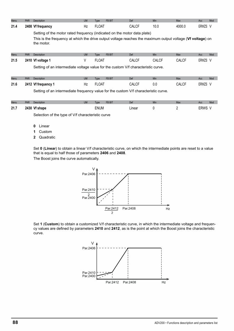
�� ADV200 • Functions description and parameters list
Menu PAR Description UM Type FB BIT Def Min Max Acc Mod
21.4 2408 Vffrequency Hz FLOAT CALCF 10.0 4000.0 ERWZS VSetting of the motor rated frequency (indicated on the motor data plate)This is the frequency at which the drive output voltage reaches the maximum output voltage (Vfvoltage) on the motor.
Menu PAR Description UM Type FB BIT Def Min Max Acc Mod
21.5 2410 Vfvoltage1 V FLOAT CALCF CALCF CALCF ERWZS VSetting of an intermediate voltage value for the custom V/f characteristic curve.
Menu PAR Description UM Type FB BIT Def Min Max Acc Mod
21.6 2412 Vffrequency1 Hz FLOAT CALCF 0.0 CALCF ERWZS VSetting of an intermediate frequency value for the custom V/f characteristic curve.
Menu PAR Description UM Type FB BIT Def Min Max Acc Mod
21.7 2430 Vfshape ENUM Linear 0 2 ERWS VSelection of the type of V/f characteristic curve
0 Linear 1 Custom � Quadratic
Set 0 (Linear) to obtain a linear V/f characteristic curve, on which the intermediate points are reset to a value that is equal to half those of parameters �406 and �40�.The Boost joins the curve automatically.
Par.24122
2
Par.2406
Par.2408
Par.2410
Par.2400
V
Hz
Set 1 (Custom) to obtain a customized V/f characteristic curve, in which the intermediate voltage and frequen-cy values are defined by parameters �410 and �41�, as is the point at which the Boost joins the characteristic curve.
Par.2406
Par.2408
Par.2410Par.2400
Par.2412 Hz
V
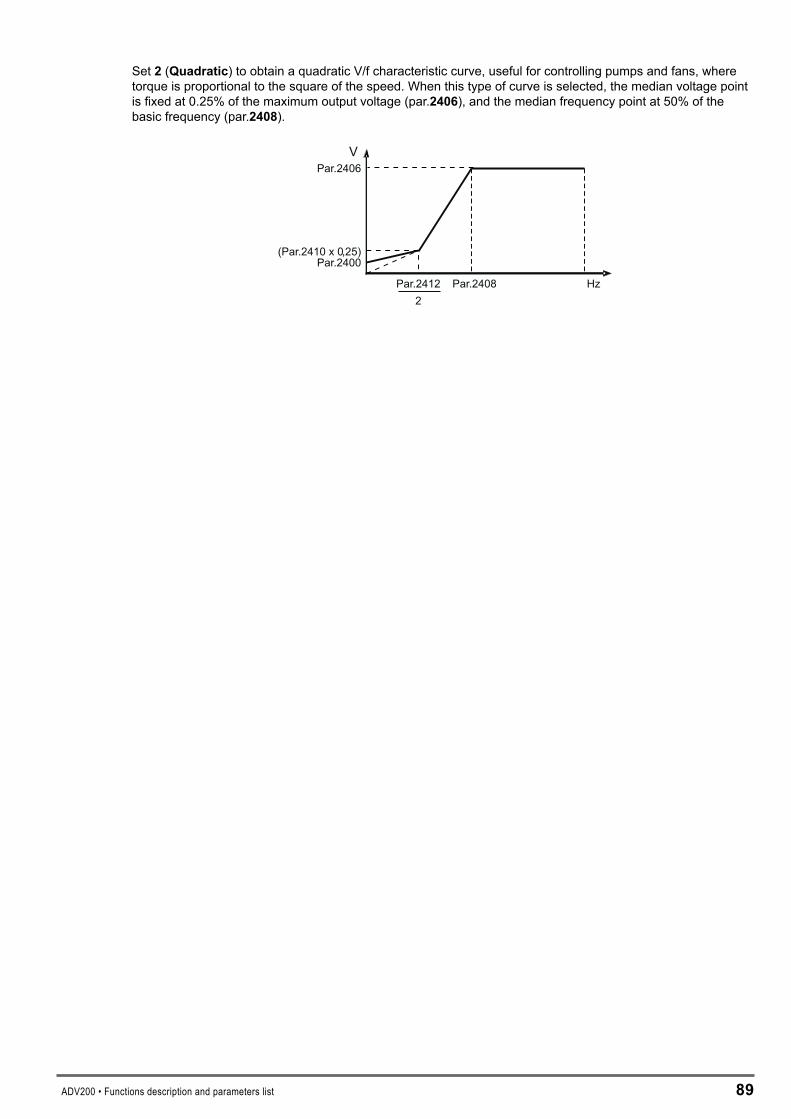
ADV200 • Functions description and parameters list �9
Set � (Quadratic) to obtain a quadratic V/f characteristic curve, useful for controlling pumps and fans, where torque is proportional to the square of the speed. When this type of curve is selected, the median voltage point is fixed at 0.25% of the maximum output voltage (par.�406), and the median frequency point at 50% of the basic frequency (par.�40�).
Par.2406
Par.2408
(Par.2410 x 0,25)Par.2400
Par.24122
V
Hz
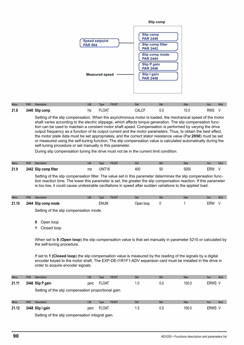
90 ADV200 • Functions description and parameters list
Slip comp
Measured speed
Speed setpointPAR 664 Slip comp filter
PAR 2442
Slip compPAR 2440
Slip I gainPAR 2448
Slip P gainPAR 2446
Slip comp modePAR 2444
Menu PAR Description UM Type FB BIT Def Min Max Acc Mod
21.8 2440 Slipcomp Hz FLOAT CALCF 0.0 10.0 RWS VSetting of the slip compensation. When the asynchronous motor is loaded, the mechanical speed of the motor shaft varies according to the electric slippage, which affects torque generation. The slip compensation func-tion can be used to maintain a constant motor shaft speed. Compensation is performed by varying the drive output frequency as a function of its output current and the motor parameters. Thus, to obtain the best effect, the motor plate data must be set appropriately, and the correct stator resistance value (Par.�050) must be set or measured using the self-tuning function, The slip compensation value is calculated automatically during the self-tuning procedure or set manually in this parameter.During slip compensation tuning the drive must not be in the current limit condition.
Menu PAR Description UM Type FB BIT Def Min Max Acc Mod
21.9 2442 Slipcompfilter ms UINT16 400 50 5000 ERW VSetting of the slip compensation filter. The value set in this parameter determines the slip compensation func-tion reaction time. The lower this parameter is set, the greater the slip compensation reaction. If this parameter is too low, it could cause undesirable oscillations in speed after sudden variations to the applied load.
Menu PAR Description UM Type FB BIT Def Min Max Acc Mod
21.10 2444 Slipcompmode ENUM Open loop 0 1 ERW VSetting of the slip compensation mode.
0 Open loop 1 Closed loop
When set to 0 (Openloop) the slip compensation value is that set manually in parameter 5210 or calculated by the self-tuning procedure.
If set to 1(Closedloop) the slip compensation value is measured by the reading of the signals by a digital encoder keyed to the motor shaft. The EXP-DE-I1R1F1-ADV expansion card must be installed in the drive in order to acquire encoder signals.
Menu PAR Description UM Type FB BIT Def Min Max Acc Mod
21.11 2446 SlipPgain perc FLOAT 1.0 0.0 100.0 ERWS VSetting of the slip compensation proportional gain.
Menu PAR Description UM Type FB BIT Def Min Max Acc Mod
21.12 2448 SlipIgain perc FLOAT 1.5 0.0 100.0 ERWS VSetting of the slip compensation integral gain.

ADV200 • Functions description and parameters list 91
Vf limit
Torque lim Pos InusePAR 2360
Torque lim Neg InusePAR 2362
Torque curr lim PosPAR 2350
Torque curr lim NegPAR 2352
Torque curr lim selPAR 2354
Vfcurrent lim I timePAR 2362
Vfcurrent lim P timePAR 2460
Menu PAR Description UM Type FB BIT Def Min Max Acc Mod
21.13 2460 VfcurrentlimPgain Hz/A FLOAT CALCF 0.0 1000.0 ERWS VSetting of the proportional gain limit in V/f mode. This is calculated automatically if the self-tuning procedure is performed.
Menu PAR Description UM Type FB BIT Def Min Max Acc Mod
21.14 2462 VfcurrentlimItime ms FLOAT CALCF 1.0 50.0 ERWS VSetting of the proportional gain limit in V/f mode. This is calculated automatically if the self-tuning procedure is performed.
Menu PAR Description UM Type FB BIT Def Min Max Acc Mod
21.15 2470 Dampinggain perc UINT16 0 0 100 ERW VSetting of the damping gain. The parameter is used to eliminate any oscillations or faults in the drive output cur-rent, deriving from configurations capable of generating oscillations in the drive/cable/motor system. If oscilla-tions occur, gradually increase the value of this parameter, until they disappear.
Menu PAR Description UM Type FB BIT Def Min Max Acc Mod
21.16 2472 Dampingthreshold1 Hz INT16 20 5 100 ERW VSetting of the first damping gain regulation threshold. These settings are usually effective for intermediate fre-quencies and make it possible to limit motor oscillations.
Menu PAR Description UM Type FB BIT Def Min Max Acc Mod
21.17 2474 Dampingthreshold2 Hz INT16 30 5 100 ERW VSetting of the second damping gain regulation threshold. These settings are usually effective for intermediate frequencies and make it possible to limit motor oscillations.
Menu PAR Description UM Type FB BIT Def Min Max Acc Mod
21.18 2480 Vfminfrequency Hz FLOAT 1.0 0 5.0 ERW VSetting of the minimum frequency in the V/f control mode. This represents the minimum output frequency, below which frequency regulations are ineffective. It is not possible to go below this value, regardless of the reference that has been set.
Menu PAR Description UM Type FB BIT Def Min Max Acc Mod
21.19 2482 Vfminfreqdelay ms UINT16 800 0 5000 ERW VSetting of the delay for the minimum frequency signal in the V/f control mode.
9� ADV200 • Functions description and parameters list
Menu PAR Description UM Type FB BIT Def Min Max Acc Mod
21.20 2490 DigVfscale FLOAT 16/32 1.0 0.0 1.0 ERWZ VSetting of a digital multiplier factor for the drive output voltage in the V/f mode.
Menu PAR Description UM Type FB BIT Def Min Max Acc Mod
21.21 2492 Vfscalesrc LINK 16/32 3374 0 16384 ERW VSelection of the origin (source) of the signal to be used to set a multiplier factor for the drive output voltage. The associable functions are listed in the “L_REF” selection list.
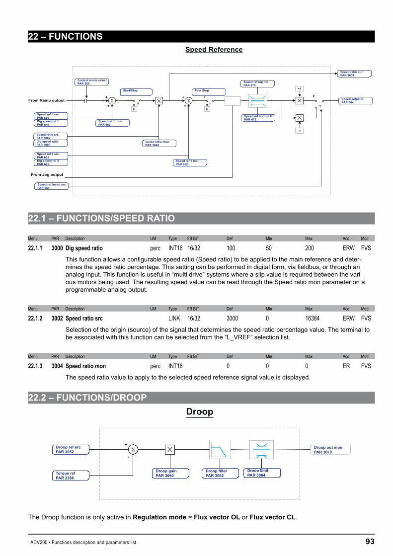
ADV200 • Functions description and parameters list 9�
��–FUNCTIONS
T
+
+
+
+
+1
-1
F
T0
F
0
FFrom Ramp output
From Jog output
Speed Reference
Speed ref 1 monPAR 660
Speed ref 2 monPAR 662
Speed ref bottom limPAR 672
Speed ref top limPAR 670
Speed setpointPAR 664
Speed ratio monPAR 3004
Start/Stop
Speed ref 1 srcPAR 650
Dig speed ratioPAR 3000
Dig speed ref 1PAR 640
Dig speed ref 2PAR 642
Speed ratio srcPAR 3002
Speed ref invert srcPAR 654
Control mode selectPAR 556
Fast Stop
Speed ref 2 srcPAR 652
Speed ratio outPAR 3004
��.1–FUNCTIONS/SPEEDRATIO
Menu PAR Description UM Type FB BIT Def Min Max Acc Mod
22.1.1 3000 Digspeedratio perc INT16 16/32 100 50 200 ERW FVSThis function allows a configurable speed ratio (Speed ratio) to be applied to the main reference and deter-mines the speed ratio percentage. This setting can be performed in digital form, via fieldbus, or through an analog input. This function is useful in “multi drive” systems where a slip value is required between the vari-ous motors being used. The resulting speed value can be read through the Speed ratio mon parameter on a programmable analog output.
Menu PAR Description UM Type FB BIT Def Min Max Acc Mod
22.1.2 3002 Speedratiosrc LINK 16/32 3000 0 16384 ERW FVSSelection of the origin (source) of the signal that determines the speed ratio percentage value. The terminal to be associated with this function can be selected from the “L_VREF” selection list.
Menu PAR Description UM Type FB BIT Def Min Max Acc Mod
22.1.3 3004 Speedratiomon perc INT16 0 0 0 ER FVSThe speed ratio value to apply to the selected speed reference signal value is displayed.
��.�–FUNCTIONS/DROOPDroop
Droop out monPAR 3070
Droop limitPAR 3064
Droop filterPAR 3062
Droop gainPAR 3060
+
-
Droop ref srcPAR 3052
Torque refPAR 2386
The Droop function is only active in Regulationmode= FluxvectorOLor FluxvectorCL.

94 ADV200 • Functions description and parameters list
The block consists of:- a node of comparison between Drooprefsrcconnected to the Analoginpof the master drive torque reference
(set Torque ref nofilter on the master analog output) and slave drive torque reference (Torque ref nofilter produced by the speed regulator).
- a proportional regulator the output of which is added to or subtracted from the reference of the slave drive speed regulator. Set Speedref1src equal to Droopoutmon.
Before it is applied to the reference of the slave drive speed regulator, the adjustment passes through a low-pass filter and a limit.
The Droop function is used to control two coupled motors.The advantage of using the Droop block is that the speed regulator can remain enabled on both drives. If using the Droop function, it can be adjusted to avoid speed regulator saturation on one of the two drives. Should there be a loss of load by one of the two drives, the adjustment provided by the Droop block is limited by the dedicated parameter.
This function is used to scale the current. This block is typically used when two motors are coupled mechanically to one another (for example if they are connected to the same shaft). They must turn at the same speed. If one of the two motors tends to turn faster, the result is a difference in the load conditions which leads to an Overload condition. The second motor acts as a brake. This causes a current unbalance, which can be eliminated by using the Droop function. An adjustment is added to or subtracted from the reference of the slave drive speed regulator (proportional to the load difference) to re-balance the two currents.
Example of machine on which the droop function can be used.
M1
DRIVEMASTER
+
M2
DRIVESLAVE
Analogoutput
Analoginput
LINE SPEED
Parameter configuration:Master drive:Analogoutxsrc connected to Torque ref nofilterSlave drive:Drooprefsrcconnected to Analoginp.Speedref1src connected to Droopoutmon.Set “Droopgain”, Drooplimit, Droop filter.

ADV200 • Functions description and parameters list 95
Menu PAR Description UM Type FB BIT Def Min Max Acc Mod
22.2.1 3052 Drooprefsrc LINK 16/32 6000 0 16384 ERW F_SThis parameter can be used to select the origin (source) of the Drooprefsrcsignal. The signal to be associat-ed with this function can be selected from the “L_LIM” selection list. Select an analog input to which an analog signal from the master drive with information about the torque reference level will be connected.
Menu PAR Description UM Type FB BIT Def Min Max Acc Mod
22.2.2 3060 Droopgain perc FLOAT 0.0 0.0 100.0 ERW F_SUse the Droopgainparameter to tune the proportional regulator gain. Setting this parameter to 0.0 forces the output of the Droop block to 0.
Menu PAR Description UM Type FB BIT Def Min Max Acc Mod
22.2.3 3062 Droopfilter ms UINT16 10 1 100 ERW F_SThe Droop filter parameter can be used to tune the filter time constant.
Menu PAR Description UM Type FB BIT Def Min Max Acc Mod
22.2.4 3064 Drooplimit rpm INT16 16/32 30 0 CALCI ERWZ F_SThe Drooplimitparameter can be used to tune the absolute value of the maximum adjustment applied by the Droop block to the speed reference.
Menu PAR Description UM Type FB BIT Def Min Max Acc Mod
22.2.5 3070 Droopoutmon rpm INT16 16/32 0 0 0 ER F_SThe Droopoutmonparameter can be used to read the size of the adjustment applied by the Droop block.This variable is typically connected to Speedref1src to add or substrat the adjustment by the Droop function to or from the speed reference.This parameter is available in the speed reference, analog output, slave->master and compare selection lists.
��.�–FUNCTIONS/INERTIACOMP
To torque control references • J
1 + s • Tƒ
Tƒ
J
Inertia Compensation
Inertia comp filterPAR 3102
Inertia compPAR 3100
Inertia comp monPAR 3104
Speed setpointPAR 664
An increase in the dynamic response of the speed regulator with a variation in the reference, canbe modified by varying the current value during the acceleration/deceleration phase, to counter the applied inertia of the machine.These parameters are calculated by the speed loop self-tuning procedure but can also be set manually by the user.

96 ADV200 • Functions description and parameters list
Menu PAR Description UM Type FB BIT Def Min Max Acc Mod
22.3.1 3100 Inertiacomp kgm2 FLOAT 0.0 0.0 100.0 ERWS F_STotal value of the inertia on the motor shaft in Kgm² identified during the self-tuning procedure. If known, this value can also be set manually by the user.
Menu PAR Description UM Type FB BIT Def Min Max Acc Mod
22.3.2 3102 Inertiacompfilter ms UINT16 30 1 100 ERW F_SSetting of a filter on the torque compensation. The filter reduces noise due to speed differentiation in the inertia block.
Menu PAR Description UM Type FB BIT Def Min Max Acc Mod
22.3.3 3104 Inertiacompmon perc FLOAT 16/32 0.0 0.0 0.0 ER F_SThe value of inertia compensation on the function block output is displayed.
��.4–FUNCTIONS/DCBRAKING
DC brakecurrent
Speed 0 ref thr
DC brakedelay
DC brakecurrent
Speed ref
Output current
DC brake state
DC brakeduration
DC brakedelay
DC braking cmd src
Output current
DC brake state
AT STOP
ON COMMAND
DC Braking
DC brake modePAR 3152
DC brake delayPAR 3154
DC brake durationPAR 3156
DC brake currentPAR 3158
DC brake statePAR 3160
DC brake modePAR 3152
DC brake statePAR 3160
DC braking cmd srcPAR 3150
DC brake delayPAR 3154
DC brake currentPAR 3158
ADV200 • Functions description and parameters list 97
The drive provides a set of parameters for managing direct current braking (DC brake).When this function is enabled, the drive injects direct current on the stator windings, generating a braking torque. The function can therefore be useful for braking the motor at around zero speed, during START and during STOP phases, or to block the rotor for short periods.It should not be used for intermediate braking operations.The kinetic energy of the machine is dissipated in the motor in the form of heat.These parameters enable complete control of the DC braking function.
Menu PAR Description UM Type FB BIT Def Min Max Acc Mod
22.4.1 3150 DCbrakingcmdsrc LINK 16 6000 0 16384 ERW FVSSelection of the origin (source) of the signal to be used for the DC braking command. The terminal or signal that can be used for this function can be defined from among those available in the “L_DIGSEL�” selection list.
Menu PAR Description UM Type FB BIT Def Min Max Acc Mod
22.4.2 3152 DCbrakemode ENUM Off 0 1 ERW FVSSetting of the direct current braking mode.
0 Off 1 At Stop
If set to 0 direct current braking is not enabled.
If set to 1 direct current braking is enabled. When the “Stop” command is enabled the motor decelerates ac-cording to the selected ramp time. When the zero speed threshold (Speed0refthr) is detected, direct current braking is enabled for the time set in DCbrakeduration.The percentage of current that is injected between the motor phases can be defined using the DCbrakingcur-rentparameter.
Menu PAR Description UM Type FB BIT Def Min Max Acc Mod
22.4.3 3154 DCbrakedelay s FLOAT 0.5 0.01 30.0 ERW FVSSetting of the delay for applying direct current braking. This delay enables the motor to demagnetize, and thus avoid an overcurrent due to the electromotive force of the motor (e.f.m.).
Menu PAR Description UM Type FB BIT Def Min Max Acc Mod
22.4.4 3156 DCbrakeduration s FLOAT 1.0 0.01 30.0 ERW FVSSetting of the duration of injection of direct current into the motor windings.
Menu PAR Description UM Type FB BIT Def Min Max Acc Mod
22.4.5 3158 DCbrakecurrent perc FLOAT 50.0 0.0 150.0 ERW FVSSetting of the direct current braking current value. This is expressed as a percentage of the rated current of the motor at full load (par. �00�Ratedcurrent).
Menu PAR Description UM Type FB BIT Def Min Max Acc Mod
22.4.6 3160 StatofrenaturaDC ENUM 16 Non active 0 1 ER FVSThe status of direct current braking is displayed.
0 Non active 1 Active
Note ! During braking the Enable command must be enabled. If this command is not present or is removed during the braking process, the drive blocks the inverter bridge and the motor stops due to inertia, without braking. Once braking has started the drive ignores the Start command and any Jog commands.

9� ADV200 • Functions description and parameters list
��.5–FUNCTIONS/MOTOROVERLOAD
The overload control function provides integrator logic to protect the motor against thermal overload. This protection presents the characteristic I²t behaviour and is an emulation of the thermal relay of the motor controlled by the ADV drive.
Menu PAR Description UM Type FB BIT Def Min Max Acc Mod
22.5.1 3200 Motorovldenable BIT 0 0 1 ERW FVSEnabling of the motor overload control.
Menu PAR Description UM Type FB BIT Def Min Max Acc Mod
22.5.2 3202 Motorovldfactor perc FLOAT 150.0 110.0 300.0 ERWS FVSSetting of the motor overload value. Percentage value of the motor rated current (par. �00�Ratedcurrent).
Menu PAR Description UM Type FB BIT Def Min Max Acc Mod
22.5.3 3204 Motorovldtime s FLOAT 30.0 10.0 300.0 ERWS FVSSetting of the motor overload duration in seconds. It represents the moment in which the protection (“Motor Overload”) is enabled, if the motor current value is above the overload set in the Motorovldfactorparameter. This alarm can be assigned to a programmable digital output (Motoroverloadtrip). The trip time depends on the motor current value and is as follows:
Motor ovld factor
Rated current
Trip time [s]
Motor current [%]
Menu PAR Description UM Type FB BIT Def Min Max Acc Mod
22.5.4 3206 Motorservicefactor perc FLOAT 100.0 25.0 200.0 ERWS FVSSetting of the motor service factor. This is the difference between the peak current and rated current. It is used to calculate the thermal image of the motor.
��.6–FUNCTIONS/BRESOVERLOAD
Braking resistors may be subject to sudden overloads following failures.Always protect resistors by using thermal protection devices.These devices do not have to interrupt the circuit where the resistor is installed, but their auxiliary contact must interrupt the power supply of the drive power section. If the resistor requires the presence of a protection con-tact, this must be used together with the one belonging to the thermal protection device.
Warning

ADV200 • Functions description and parameters list 99
Menu PAR Description UM Type FB BIT Def Min Max Acc Mod
22.6.1 3250 Brescontrol BIT 0 0 1 ERWZ FVSEnabling of the overload control of the external braking resistor.
Menu PAR Description UM Type FB BIT Def Min Max Acc Mod
22.6.2 3252 Bresvalueohm ohm FLOAT SIZE 10.0 1000.0 ERWS FVSSetting of the ohm value of the external braking resistor.
Menu PAR Description UM Type FB BIT Def Min Max Acc Mod
22.6.3 3254 Brescontpower kW FLOAT SIZE 0.1 100.0 ERWS FVSSetting of the power that can be continuously dissipated by the external braking resistor.
Menu PAR Description UM Type FB BIT Def Min Max Acc Mod
22.6.4 3256 Bresoverloadfactor FLOAT SIZE 1.5 10.0 ERWS FVSSetting of the external resistor overload factor.
Menu PAR Description UM Type FB BIT Def Min Max Acc Mod
22.6.5 3258 Bresoverloadtime s FLOAT SIZE 0.5 50.0 ERWS FVSSetting of the intervention time of the external braking resistor overload.
��.7–FUNCTIONS/DOUBLEPARSET
Set 0 Set 1
Par set 0 to 1 copy
Par set select src
Par set select mon
PAR. 3306
PAR. 3300
PAR. 3302
Two independent sets of parameters can be stored in the ADV200 drive. These can be selected via the keypad or by using an external command.
This makes it possible to change all the drive parameters quickly and automatically according to the various operating requirements. For example, two motors with different characteristics can be controlled alternately.
MDPLC application parameters are not included in the two sets of parameters. This makes it possible to switch be-tween all drive parameters in two separate groups, while having a single set of parameters for the application.
100 ADV200 • Functions description and parameters list
Menu PAR Description UM Type FB BIT Def Min Max Acc Mod
22.7.1 3300 Parsetenable ENUM Disable 0 1 ERW FVSEnabling of management of two parameter sets
0 Disable 1 Enable
When set to 0 only one parameter set is managed (the one used as the default set).
If set to 1 two separate parameter sets can be configured. These can be selected using a command signal on a digital input of the terminal strip.
Menu PAR Description UM Type FB BIT Def Min Max Acc Mod
22.7.2 3302 Parsetselectsrc LINK 16 6000 0 16384 ERWZ FVSSelection of the origin (source) of the signal to be used to select the parameter set to be used. The terminal or digital command that can be associated with this function can be selected from among those available in the “L_DIGSEL�” selection list.
Menu PAR Description UM Type FB BIT Def Min Max Acc Mod
22.7.3 3304 Parsetselectmon ENUM 16 Set 0 0 0 ER FVSThe parameter set currently in use is displayed.
0 Set 0 1 Set 1
Menu PAR Description UM Type FB BIT Def Min Max Acc Mod
22.7.4 3306 Parset0to1copy BIT 0 0 1 ERW FVSProceduresforsettingupandmanagingthedoubleparameterset
Creatingthesecondset:
This function copies parameter set 0 onto set 1. Before enabling management of the double parameter set, the first set should be programmed with the correct values.
When the first set is ready, the second can be activated as follows:
1 Activate management of the double parameter set by enabling parameter ��00Parsetenable.� Copy set 0 onto set 1 using command ��06Parset0to1copy. This creates an initial parameter base in set 1 to which changes can be made. Save the parameters.� Activate set 1 using parameter ��0�Parsetselectsrc. To select set 1 manually, set this parameter to “One”. Otherwise select the desired source.4 Modify the parameters in set 1 as necessary.5 Save the parameters.
You can change the set being used by changing the source selected in parameter ��0�Parsetselectsrc. This can only be changed with the drive disabled.
When the double parameter set is active, the number of the set being used is shown next to the number of each parameter on the keypad.
Modifyingandsavingparameters:
When the double parameter set is active, any parameters that need to be the same in the two sets must be modified in each set separately.
Parameters are only saved in the set that is active at the time. To save both sets, you must first save one and then select and save the other.
Note ! Any changes to the parameters regarding the “parameter sets”, performed when enabled, will be lost at the next switching unless a Parset0to1copy command is sent. To save data permanently (even when the drive is switched off), send the Saveparameters com-mand (DRIVE CONFIG menu).

ADV200 • Functions description and parameters list 101
��.�–FUNCTIONS/SPEEDCAPTURE
Menu PAR Description UM Type FB BIT Def Min Max Acc Mod
22.8.1 3350 Speedcapture ENUM Disable 0 1 ERW FV_Setting of the function that allows the drive to capture a motor that is already rotating.This function enables identification of the speed of an already rotating motor in V/f control mode to permit enabling of the drive without sudden stress in the load. This function can also be used in the case of restart after an alarm condition. The procedure may last several seconds according to motor and setting of the regulation parameters. If the motor has already stopped when this function is enabled, it may accelerate and rotate at a certain speed for a few seconds until the search has been completed and recognition of 0 speed.
0 Disable1 Enable
When set to0 the speed capture function is disabled. When connected the drive starts with a zero frequency.
When set to 1 the speed capture function is enabled. When the drive is connected the motor speed is meas-ured and the output voltage and frequency are set appropriately. The drive then moves to the set reference. This function is only available in the flux oriented vector mode.
Main fields of application:
- Capturing a motor already set in motion by the load (for example pump motors driven by the fluid)- Reconnection after an alarm.- If the speed reference passes through the ramp circuit, the motor speed, with Auto capture = ON, is reached
following the set ramp times.
Note ! If this function is disabled, make sure the motor is not moving when the drive is connected, otherwise the drive could be blocked due to the intervention of the overcurrent or overvoltage protections.
Menu PAR Description UM Type FB BIT Def Min Max Acc Mod
22.8.2 3364 Vfcatchstartfreq Hz FLOAT 50.0 -500.0 500.0 ERWZ VSetting of the starting frequency during catch on-the-fly of a motor in Vf operating mode.
Menu PAR Description UM Type FB BIT Def Min Max Acc Mod
22.8.3 3366 Vfcatchdelay ms UINT16 1000 10 10000 ERWZ VSetting of the delay for motor demagnetization before searching for synchronization.
Menu PAR Description UM Type FB BIT Def Min Max Acc Mod
22.8.4 3368 Vfsearchtime s FLOAT 2.0 1.0 10.0 ERW VDetermines the speed at which the inverter output frequency changes. Represents the time in which the fre-quency would change from zero to the motor rated frequency if the output current were equal to the motor rated current.
Menu PAR Description UM Type FB BIT Def Min Max Acc Mod
22.8.5 3370 VfcatchPgain perc FLOAT 10.0 0.0 100.0 ERW VSetting of the proportional gain during catch on-the-fly of a motor in Vf operating mode.
Menu PAR Description UM Type FB BIT Def Min Max Acc Mod
22.8.6 3372 VfcatchItime ms UINT16 200 200 1000 ERW VSetting of the integral time during catch on-the-fly of a motor in Vf operating mode.

10� ADV200 • Functions description and parameters list
��.9–FUNCTIONS/POWERLOSS
Power loss
Speed setpointPAR 664
Motor speedPAR 260
To torque control
Powerloss nextratioPAR 3446
Powerloss rampdownPAR 3442
Powerloss main srcPAR 3440
Powerloss I timePAR 3422
Powerloss accel timePAR 3402
Powerloss decel timePAR 3404
Powerloss functionPAR 3400
Powerloss P gainPAR 3420
Powerloss nextactivePAR 3448
Voltage detect
Powerloss modePAR 3438
Supply voltage
VDC
Speed ref
The drive is switched off ifthe power supply is notrestored
The power supply is restored while the functionis active
Restart possible when the external sensor detectsthat the supply voltage has been restored.
Speed reference Speed
Ploss staveactive
Powerloss end-of-ramp

ADV200 • Functions description and parameters list 10�
Menu PAR Description UM Type FB BIT Def Min Max Acc Mod
22.9.1 3400 Powerlossfunction ENUM Disable 0 1 ERWZ F__0 Disable1 Enable
The purpose of this function is to prevent the uncontrolled stopping of the machine in case of an interruption to the power supply due to an undervoltage alarm. When the function is enabled the drive controls the motor so as to force regeneration; the kinetic energy from the load is temporarily used to “sustain” the power supply to the drive so that the machine stops under control. The function is only effective with loads that accumulate enough kinetic energy (typically loads with a high mo-ment of inertia). It cannot be used for “passive loads”. If it is important to control machine deceleration very closely, the Powerloss function must be used with a brak-ing resistor and braking control must be enabled.
Slavecontrol In some applications several drives are powered via DC bus. The master drive is usually the one that controls the motor with the highest inertial load. The Powerloss function should be enabled on this drive. The speed of the other slave drives must follow that of the master drive. Together they provide the “sustaining” power supply during braking in case of an interruption in the power supply. In this case the master drive calculates the ratio between its speed and the line speed, sending a signal to the slave drives to adjust their speed to that of the master. The master and slave can be connected via an analog I/O or fieldbus. The calculated ratio signal is used on the slave drives to control the speed ratio.
The following alarms must be set as described below for the function to operate correctly.
Par.455�SpdRefLossactivity=Ignore
Since the current reference and limit are controlled internally, there would be a difference between the speed reference and the motor speed, with activation of the Ref Loss alarm.
Par.4660SpdFbkLossactivity=Ignore
The phase loss may not be properly detected and in any case any alarm sould be ignored.
The Powerloss function can only be used in the field-oriented vector control mode.
Menu PAR Description UM Type FB BIT Def Min Max Acc Mod
22.9.2 3402 Powerlossacctime s FLOAT 10.0 0.01 100.0 ERW F__Setting of the acceleration time used during Powerloss operating mode. The acceleration ramp time is used when restart has been selected and can be adjusted according to machine requirements.
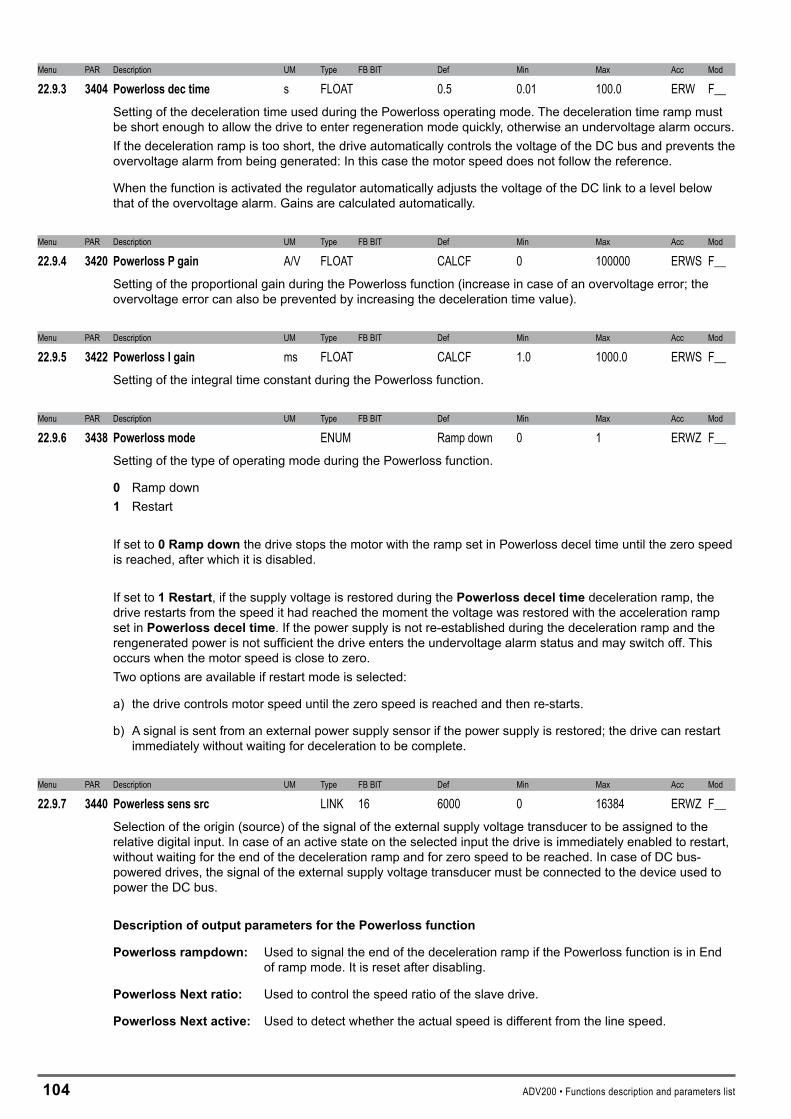
104 ADV200 • Functions description and parameters list
Menu PAR Description UM Type FB BIT Def Min Max Acc Mod
22.9.3 3404 Powerlossdectime s FLOAT 0.5 0.01 100.0 ERW F__Setting of the deceleration time used during the Powerloss operating mode. The deceleration time ramp must be short enough to allow the drive to enter regeneration mode quickly, otherwise an undervoltage alarm occurs. If the deceleration ramp is too short, the drive automatically controls the voltage of the DC bus and prevents the overvoltage alarm from being generated: In this case the motor speed does not follow the reference.
When the function is activated the regulator automatically adjusts the voltage of the DC link to a level below that of the overvoltage alarm. Gains are calculated automatically.
Menu PAR Description UM Type FB BIT Def Min Max Acc Mod
22.9.4 3420 PowerlossPgain A/V FLOAT CALCF 0 100000 ERWS F__Setting of the proportional gain during the Powerloss function (increase in case of an overvoltage error; the overvoltage error can also be prevented by increasing the deceleration time value).
Menu PAR Description UM Type FB BIT Def Min Max Acc Mod
22.9.5 3422 PowerlossIgain ms FLOAT CALCF 1.0 1000.0 ERWS F__Setting of the integral time constant during the Powerloss function.
Menu PAR Description UM Type FB BIT Def Min Max Acc Mod
22.9.6 3438 Powerlossmode ENUM Ramp down 0 1 ERWZ F__Setting of the type of operating mode during the Powerloss function.
0 Ramp down1 Restart
If set to 0Rampdown the drive stops the motor with the ramp set in Powerloss decel time until the zero speed is reached, after which it is disabled.
If set to 1Restart, if the supply voltage is restored during the Powerlossdeceltimedeceleration ramp, the drive restarts from the speed it had reached the moment the voltage was restored with the acceleration ramp set in Powerlossdeceltime. If the power supply is not re-established during the deceleration ramp and the rengenerated power is not sufficient the drive enters the undervoltage alarm status and may switch off. This occurs when the motor speed is close to zero.Two options are available if restart mode is selected:
a) the drive controls motor speed until the zero speed is reached and then re-starts.
b) A signal is sent from an external power supply sensor if the power supply is restored; the drive can restart immediately without waiting for deceleration to be complete.
Menu PAR Description UM Type FB BIT Def Min Max Acc Mod
22.9.7 3440 Powerlesssenssrc LINK 16 6000 0 16384 ERWZ F__Selection of the origin (source) of the signal of the external supply voltage transducer to be assigned to the relative digital input. In case of an active state on the selected input the drive is immediately enabled to restart, without waiting for the end of the deceleration ramp and for zero speed to be reached. In case of DC bus-powered drives, the signal of the external supply voltage transducer must be connected to the device used to power the DC bus.
DescriptionofoutputparametersforthePowerlossfunction
Powerlossrampdown: Used to signal the end of the deceleration ramp if the Powerloss function is in End of ramp mode. It is reset after disabling.
PowerlossNextratio: Used to control the speed ratio of the slave drive.
PowerlossNextactive: Used to detect whether the actual speed is different from the line speed.
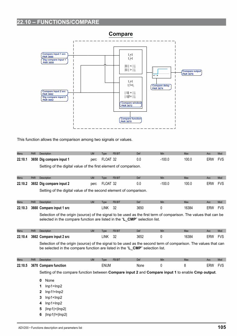
ADV200 • Functions description and parameters list 105
��.10–FUNCTIONS/COMPARE
II
||
12
1 2
1 2
1 2
=!=
| = | ||!= | |
II
IIII
||
II
12
12
1 2
1 2
<>
| < | || > | |
II
IIII
Compare
Compare input 1 srcPAR 3660Dig c 1P
ompare inputAR 3650
Compare input 2 srcPAR 3662Dig compare input 2PAR 3652
Compare functionPAR 3670
Compare delayPAR 3674
Compare outputPAR 3676
Compare windowPAR 3672
This function allows the comparison among two signals or values.
Menu PAR Description UM Type FB BIT Def Min Max Acc Mod
22.10.1 3650 Digcompareinput1 perc FLOAT 32 0.0 -100.0 100.0 ERW FVSSetting of the digital value of the first element of comparison.
Menu PAR Description UM Type FB BIT Def Min Max Acc Mod
22.10.2 3652 Digcompareinput2 perc FLOAT 32 0.0 -100.0 100.0 ERW FVSSetting of the digital value of the second element of comparison.
Menu PAR Description UM Type FB BIT Def Min Max Acc Mod
22.10.3 3660 Compareinput1src LINK 32 3650 0 16384 ERW FVSSelection of the origin (source) of the signal to be used as the first term of comparison. The values that can be selected in the compare function are listed in the “L_CMP” selection list.
Menu PAR Description UM Type FB BIT Def Min Max Acc Mod
22.10.4 3662 Compareinput2src LINK 32 3652 0 16384 ERW FVSSelection of the origin (source) of the signal to be used as the second term of comparison. The values that can be selected in the compare function are listed in the “L_CMP” selection list.
Menu PAR Description UM Type FB BIT Def Min Max Acc Mod
22.10.5 3670 Comparefunction ENUM None 0 8 ERW FVSSetting of the compare function between Compareinput�and Compareinput1to enable Cmpoutput.
0 None 1 Inp1=Inp2 � Inp1!=Inp2 � Inp1<Inp2 4 Inp1>Inp2 5 |Inp1|=|Inp2| 6 |Inp1|!=|Inp2|

106 ADV200 • Functions description and parameters list
7 |Inp1|<|Inp2| � |Inp1|>|Inp2|
If set to 0 the comparator is not enabled
If set to 1 the comparator output is enabled when the value of Comparedigitalinp1 is inside the window resulting from the value of Comparedigitalinp2 ± the tolerance set via the ComparatorWindow.
If set to � the comparator output is enabled when the value of Comparedigitalinp1 is not inside the window resulting from the value of Comparedigitalinp2 ± the tolerance set via the ComparatorWindow.
If set to � the comparator output is enabled when Compareinput1is less than Compareinput�.
If set to 4 the comparator output is enabled when Compareinput1is greater than Compareinput�.
If set to 5 the comparator output is enabled when the value of Comparedigitalinp1 is inside the window resulting from the absolute value of Comparedigitalinp2 ± the tolerance set via the ComparatorWindow.
If set to 6 the comparator output is enabled when the absolute value of Comparedigitalinp1 is not inside the window resulting from the absolute value of Comparedigitalinp� ± the tolerance set via the ComparatorWindow.
If set to 7 the comparator output is enabled when the absolute value of Comparedigitalinp1 is less than the absolute value of Comparedigitalinp�.
If set to � the comparator output is enabled when the absolute value of Digitalcomparinp1 is more than the absolute value of Digitalcomparin�.
Menu PAR Description UM Type FB BIT Def Min Max Acc Mod
22.10.6 3672 Comparewindow perc FLOAT 0.0 0.0 100.0 ERW FVSSetting of the tolerance window for comparing the Compareinput1 and Compareinput� signals.
Menu PAR Description UM Type FB BIT Def Min Max Acc Mod
22.10.7 3674 Comparedelay s FLOAT 0.0 0.0 30.0 ERW FVSSetting of the delay for signalling the result of the comparison.
Menu PAR Description UM Type FB BIT Def Min Max Acc Mod
22.10.8 3676 Compareoutput BIT 16 0 0 1 ER FVSThe status of the comparator output is displayed:
0 The result of the set comparison is negative1 The result of the set comparison is positive
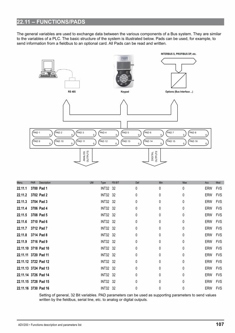
ADV200 • Functions description and parameters list 107
��.11–FUNCTIONS/PADS
The general variables are used to exchange data between the various components of a Bus system. They are similar to the variables of a PLC. The basic structure of the system is illustrated below. Pads can be used, for example, to send information from a fieldbus to an optional card. All Pads can be read and written.
PAD 10
PAD 20
PAD 30
PAD 40
PAD 50
PAD 60
PAD 70
PAD 80
PAD 90
PAD 100
PAD 110
PAD 120
PAD 130
PAD 140
PAD 150
PAD 160
ANAL
OG
OU
TPU
TS
DIG
ITA
LO
UTP
UTS
Options (Bus Interface ...)
INTERBUS S, PROFIBUS DP, etc.
KeypadRS 485
Menu PAR Description UM Type FB BIT Def Min Max Acc Mod
22.11.1 3700 Pad1 INT32 32 0 0 0 ERW FVS22.11.2 3702 Pad2 INT32 32 0 0 0 ERW FVS22.11.3 3704 Pad3 INT32 32 0 0 0 ERW FVS22.11.4 3706 Pad4 INT32 32 0 0 0 ERW FVS22.11.5 3708 Pad5 INT32 32 0 0 0 ERW FVS22.11.6 3710 Pad6 INT32 32 0 0 0 ERW FVS22.11.7 3712 Pad7 INT32 32 0 0 0 ERW FVS22.11.8 3714 Pad8 INT32 32 0 0 0 ERW FVS22.11.9 3716 Pad9 INT32 32 0 0 0 ERW FVS22.11.10 3718 Pad10 INT32 32 0 0 0 ERW FVS22.11.11 3720 Pad11 INT32 32 0 0 0 ERW FVS22.11.12 3722 Pad12 INT32 32 0 0 0 ERW FVS22.11.13 3724 Pad13 INT32 32 0 0 0 ERW FVS22.11.14 3726 Pad14 INT32 32 0 0 0 ERW FVS22.11.15 3728 Pad15 INT32 32 0 0 0 ERW FVS22.11.16 3730 Pad16 INT32 32 0 0 0 ERW FVS
Setting of general, 32 Bit variables. PAD parameters can be used as supporting parameters to send values written by the fieldbus, serial line, etc. to analog or digital outputs.

10� ADV200 • Functions description and parameters list
��–COMMUNICATION
��.1–COMMUNICATION/RS4�5
The ADV200 drive is provided with a standard port (9 pole sub-D connector: XS) for connecting the RS485 serial line used for drive-PC point-to-point communication (via the GF-eXpress configuration software) or for the multidrop con-nection.
The RS485 serial line format is: 8 data bits, no parity and one stop bit.
Menu PAR Description UM Type FB BIT Def Min Max Acc Mod
23.1.1 3800 Driveaddress UINT16 1 1 255 ERW FVSSetting of the address to which the drive responds when connected to the RS485 serial line.
Menu PAR Description UM Type FB BIT Def Min Max Acc Mod
23.1.2 3802 Serialbaudrate ENUM 38400 0 2 ERW FVSSetting of the RS485 serial communication speed (Baud Rate).
0 9600 1 19200 � 38400 � 57600 4 115200
Menu PAR Description UM Type FB BIT Def Min Max Acc Mod
23.1.3 3804 Serialprotocol ENUM Modbus 0 1 ERW FVSSetting of the serial communication protocol:
0 Modbus 1 Jbus Setting to 0 selects the Modbus RTU (Remote Terminal Unit) serial communication protocol.
Setting to 1 selects the Jbus serial communication protocol. The Jbus protocol is functionally identical to the Modbus, except for the different numbering of addresses: in the Modbus these start from zero (0000 = 1st address) while in the JBUS they start from one (0001 = 1st address) and maintain this difference throughout numbering.
Menu PAR Description UM Type FB BIT Def Min Max Acc Mod
23.1.4 3806 Serialdelay ms UINT16 0 0 1000 ERW FVSSetting of the minimum delay between the drive receiving the last byte and starting its response. This delay avoids conflicts on the serial line when the RS485 interface that is used has not been pre-set for automatic Tx/Rx switching. The parameter only concerns the use of the standard RS485 serial line.
Example: if the delay in Tx/Rx switching on the master is a maximum of 20ms, the Ser answer delay parameter must be set to at least 20ms: 22ms
Menu PAR Description UM Type FB BIT Def Min Max Acc Mod
23.1.5 3808 Serialswapdata BIT 0 0 1 ERW FVSThis parameter enables the exchange of the reading of the High and Low parts of the words for FLOAT type parameters when using the Modbus protocol.

ADV200 • Functions description and parameters list 109
��.�–COMMUNICATION/FIELDBUSCONFIG
Menu PAR Description UM Type FB BIT Def Min Max Acc Mod
23.2.1 4000 Fieldbustype ENUM Off 0 5 RW FVSSetting of the type of fieldbus to be used.
0 Off1 CanOpen� DeviceNet� Profibus10 DS402 profile�0 Profidrive profile
If set to 0 no fieldbus is selected.
If set to 1 the CanOpen fieldbus profile is selected.
If set to � the ProfiBus-DP fieldbus profile is selected.
If set to � the DeviceNet fieldbus profile is selected.
If set to 10 the DS402 fieldbus is selected.
If set to �0 the Profidrive fieldbus is selected.
Menu PAR Description UM Type FB BIT Def Min Max Acc Mod
23.2.2 4004 Fieldbusbaudrate ENUM 500k 0 12 RW FVSSetting of the communication network speed (Baud Rate).
0 Automatico1 125k� 250k� 500k4 1M5 96006 192007 93750� 187.5k9 1.5M103M11 6M1�12M
Menu PAR Description UM Type FB BIT Def Min Max Acc Mod
23.2.3 4006 Fieldbusaddress INT16 3 0 255 RW FVSSetting of the node address of the drive when connected to the network.

110 ADV200 • Functions description and parameters list
Menu PAR Description UM Type FB BIT Def Min Max Acc Mod
23.2.4 4010 FieldbusM->Senable ENUM Enable 0 1 ERWZ FVSSetting of fieldbus data updating. 0 Disable1 Enable
If set to 0, the possibility of sending commands and references from the drive PLC via the fieldbus is disabled. If set to 1 the possibility of sending commands and references from the drive PLC via the fieldbus is enabled.
Menu PAR Description UM Type FB BIT Def Min Max Acc Mod
23.2.5 4012 Fieldbusalarmmode INT32 0 0 1 ERWZ FVSSetting of the OptBusFault alarm generation mode. 0 Off1 On If set to0 the alarm is only generated if the drive is enabled. If set to 1 the alarm is generated even with the drive disabled.
Menu PAR Description UM Type FB BIT Def Min Max Acc Mod
23.2.6 4014 Fieldbusstate ENUM Stop 0 7 R FVSThe logic status of the fieldbus connection is displayed. The value depends on the type of bus that is used.
0 Stop1 PreOperational� Operational
These logic states are displayed if the selected fieldbus is CANopen.
� Error4 WaitPRM5 WaitCFG6 DataExchange7 DPError
These logic states are displayed if the selected fieldbus is Profibus.

ADV200 • Functions description and parameters list 111
��.�–COMMUNICATION/FIELDBUSM�S
Menu PAR Description UM Type FB BIT Def Min Max Acc Mod
23.3.1 4020 FieldbusM->S1dest ILINK 0 0 0 R FVS23.3.5 4030 FieldbusM->S2dest ILINK 0 0 0 R FVS23.3.9 4040 FieldbusM->S3dest ILINK 0 0 0 R FVS23.3.13 4050 FieldbusM->S4dest ILINK 0 0 0 R FVS23.3.17 4060 FieldbusM->S5dest ILINK 0 0 0 R FVS23.3.21 4070 FieldbusM->S6dest ILINK 0 0 0 R FVS23.3.25 4080 FieldbusM->S7dest ILINK 0 0 0 R FVS23.3.29 4090 FieldbusM->S8dest ILINK 0 0 0 R FVS23.3.33 4100 FieldbusM->S9dest ILINK 0 0 0 R FVS23.3.37 4110 FieldbusM->S10dest ILINK 0 0 0 R FVS23.3.41 4120 FieldbusM->S11dest ILINK 0 0 0 R FVS23.3.45 4130 FieldbusM->S12dest ILINK 0 0 0 R FVS23.3.49 4140 FieldbusM->S13dest ILINK 0 0 0 R FVS23.3.53 4150 FieldbusM->S14dest ILINK 0 0 0 R FVS23.3.57 4160 FieldbusM->S15dest ILINK 0 0 0 R FVS23.3.61 4170 FieldbusM->S16dest ILINK 0 0 0 R FVS
The src parameter associated with the M->SX channel is displayed. This is useful for quickly understanding where a bus channel is connected. A channel can only be associated with a parameter by modifying the src parameter in its menu.When the src parameter is associated with an M->S bus channel, that channel is automatically programmed with a relative value on the sys parameter of the location of the data written by the Master on the Slave.
Menu PAR Description UM Type FB BIT Def Min Max Acc Mod
23.3.2 4022 FieldbusM->S1sys ENUM Not assigned 0 8 RW FVS23.3.6 4032 FieldbusM->S2sys ENUM Not assigned 0 8 RW FVS23.3.10 4042 FieldbusM->S3sys ENUM Not assigned 0 8 RW FVS23.3.14 4052 FieldbusM->S4sys ENUM Not assigned 0 8 RW FVS23.3.18 4062 FieldbusM->S5sys ENUM Not assigned 0 8 RW FVS23.3.22 4072 FieldbusM->S6sys ENUM Not assigned 0 8 RW FVS23.3.26 4082 FieldbusM->S7sys ENUM Not assigned 0 8 RW FVS23.3.30 4092 FieldbusM->S8sys ENUM Not assigned 0 8 RW FVS23.3.34 4102 FieldbusM->S9sys ENUM Not assigned 0 8 RW FVS23.3.38 4112 FieldbusM->S10sys ENUM Not assigned 0 8 RW FVS23.3.42 4122 FieldbusM->S11sys ENUM Not assigned 0 8 RW FVS23.3.46 4132 FieldbusM->S12sys ENUM Not assigned 0 8 RW FVS23.3.50 4142 FieldbusM->S13sys ENUM Not assigned 0 8 RW FVS23.3.54 4156 FieldbusM->S14div FLOAT 1.0 1.0 1000.0 ERW FVS23.3.58 4162 FieldbusM->S15sys ENUM Not assigned 0 8 RW FVS23.3.62 4172 FieldbusM->S16sys ENUM Not assigned 0 8 RW FVS
Setting of the format of the datum received on the channel. When the src parameter is programmed, the for-mat is automatically programmed on the relative sys. If the src parameter is reset to null, the format does not change. The value of the format can be selected from the following list, according to the parameter selected as the source:

11� ADV200 • Functions description and parameters list
0 Not assigned1 Count 16� Count 32� Fill 164 Fill 325 Mdplc 166 Mdplc 327 Eu� Eu float
If set to 0 the channel is not assigned.If set to 1 the datum is assigned a 16-bit count.If set to � the datum is assigned a 32-bit count.If set to � 16 bits on the channel are reserved for the datum, not used.If set to 4 32 bits on the channel are reserved for the datum, not used.If set to 5 the datum is assigned a 16-bit count used by MDPLC.If set to 6 the datum is assigned a 32-bit count used by MDPLC.If set to 7 the datum is assigned engineering units on a 16-bit integer.If set to � the datum is assigned engineering units on a 32-bit integer.
Note! If the sys parameter is notassigned, none of the subsequent fieldbus channels are read, even if programmed.
Menu PAR Description UM Type FB BIT Def Min Max Acc Mod
23.3.3 4024 FieldbusM->S1mon INT32 32 0 0 0 ER FVS23.3.7 4034 FieldbusM->S2mon INT32 32 0 0 0 ER FVS23.3.11 4044 FieldbusM->S3mon INT32 32 0 0 0 ER FVS23.3.15 4054 FieldbusM->S4mon INT32 32 0 0 0 ER FVS23.3.19 4064 FieldbusM->S5mon INT32 32 0 0 0 ER FVS23.3.23 4074 FieldbusM->S6mon INT32 32 0 0 0 ER FVS23.3.27 4084 FieldbusM->S7mon INT32 32 0 0 0 ER FVS23.3.31 4094 FieldbusM->S8mon INT32 32 0 0 0 ER FVS23.3.35 4104 FieldbusM->S9mon INT32 32 0 0 0 ER FVS23.3.39 4114 FieldbusM->S10mon INT32 32 0 0 0 ER FVS23.3.43 4124 FieldbusM->S11mon INT32 32 0 0 0 ER FVS23.3.47 4134 FieldbusM->S12mon INT32 32 0 0 0 ER FVS23.3.51 4144 FieldbusM->S13mon INT32 32 0 0 0 ER FVS23.3.55 4152 FieldbusM->S14sys ENUM Not assigned 0 8 RW FVS23.3.59 4164 FieldbusM->S15mon INT32 32 0 0 0 ER FVS23.3.63 4174 FieldbusM->S16mon INT32 32 0 0 0 ER FVS
The value received from the bus is displayed. This parameter must be associated with the src parameter to en-able the M->S channel.
The user may modify the M->Sand by S->Msys parameters. The consistency of the sys with the parameter assigned to the channel is checked.
AFieldbusM->SXMonparametercanonlybeassignedtoasingle“src”.Ifassignedtomorethanonesrc, an error signal is generated during fieldbus initialization.

ADV200 • Functions description and parameters list 11�
Menu PAR Description UM Type FB BIT Def Min Max Acc Mod
23.3.4 4026 FieldbusM->S1div FLOAT 1.0 1.0 1000.0 ERW FVS23.3.8 4036 FieldbusM->S2div FLOAT 1.0 1.0 1000.0 ERW FVS23.3.12 4046 FieldbusM->S3div FLOAT 1.0 1.0 1000.0 ERW FVS23.3.16 4056 FieldbusM->S4div FLOAT 1.0 1.0 1000.0 ERW FVS23.3.20 4066 FieldbusM->S5div FLOAT 1.0 1.0 1000.0 ERW FVS23.3.24 4076 FieldbusM->S6div FLOAT 1.0 1.0 1000.0 ERW FVS23.3.28 4086 FieldbusM->S7div FLOAT 1.0 1.0 1000.0 ERW FVS23.3.32 4096 FieldbusM->S8div FLOAT 1.0 1.0 1000.0 ERW FVS23.3.36 4106 FieldbusM->S9div FLOAT 1.0 1.0 1000.0 ERW FVS23.3.40 4116 FieldbusM->S10div FLOAT 1.0 1.0 1000.0 ERW FVS23.3.44 4126 FieldbusM->S11div FLOAT 1.0 1.0 1000.0 ERW FVS23.3.48 4136 FieldbusM->S12div FLOAT 1.0 1.0 1000.0 ERW FVS23.3.52 4146 FieldbusM->S13div FLOAT 1.0 1.0 1000.0 ERW FVS23.3.56 4154 FieldbusM->S14mon INT32 32 0 0 0 ER FVS23.3.60 4166 FieldbusM->S15div FLOAT 1.0 1.0 1000.0 ERW FVS23.3.64 4176 FieldbusM->S16div FLOAT 1.0 1.0 1000.0 ERW FVS
The Div M->Sx fieldbus parameters can be used to increase the resolution of the datum sent on the bus to the drive in the corresponding channel in EU and EU_float exchange mode. The parameter value is used by the drive as the divider of the incoming datum, so that a number with decimal digits can be transferred. N.B.: You must check the size in bits of the datum that is sent to make sure that the maximum value in
bits fits in a 16-bit integer. For example, if specifying the divider as “Fieldbus M->Sn div” = 1000, the maximum value that can be used for the exchanged datum is 32.768 (32768/1000).
.Example: Div M->Sx fieldbus = 10, M->S1 fieldbus par = Ramprefsrc1, Sys M->S1 fieldbus = Eu. If
the PLC sends the decimal value 1000 on the first word the value of rampref1 on the drive is 1000/10 = 100.
��.4–COMMUNICATION/FIELDBUSS�M
Menu PAR Description UM Type FB BIT Def Min Max Acc Mod
23.4.1 4180 FieldbusS->M1src LINK 32 6000 0 16384 RW FVS23.4.5 4190 FieldbusS->M2src LINK 32 6000 0 16384 RW FVS23.4.9 4200 FieldbusS->M3src LINK 32 6000 0 16384 RW FVS23.4.13 4210 FieldbusS->M4src LINK 32 6000 0 16384 RW FVS23.4.17 4220 FieldbusS->M5src LINK 32 6000 0 16384 RW FVS23.4.21 4230 FieldbusS->M6src LINK 32 6000 0 16384 RW FVS23.4.25 4240 FieldbusS->M7src LINK 32 6000 0 16384 RW FVS23.4.29 4250 FieldbusS->M8src LINK 32 6000 0 16384 RW FVS23.4.33 4260 FieldbusS->M9src LINK 32 6000 0 16384 RW FVS23.4.37 4270 FieldbusS->M10src LINK 32 6000 0 16384 RW FVS23.4.41 4280 FieldbusS->M11src LINK 32 6000 0 16384 RW FVS23.4.45 4290 FieldbusS->M12src LINK 32 6000 0 16384 RW FVS23.4.49 4300 FieldbusS->M13src LINK 32 6000 0 16384 RW FVS23.4.53 4310 FieldbusS->M14src LINK 32 6000 0 16384 RW FVS23.4.57 4320 FieldbusS->M15src LINK 32 6000 0 16384 RW FVS23.4.61 4330 FieldbusS->M16src LINK 32 6000 0 16384 RW FVS
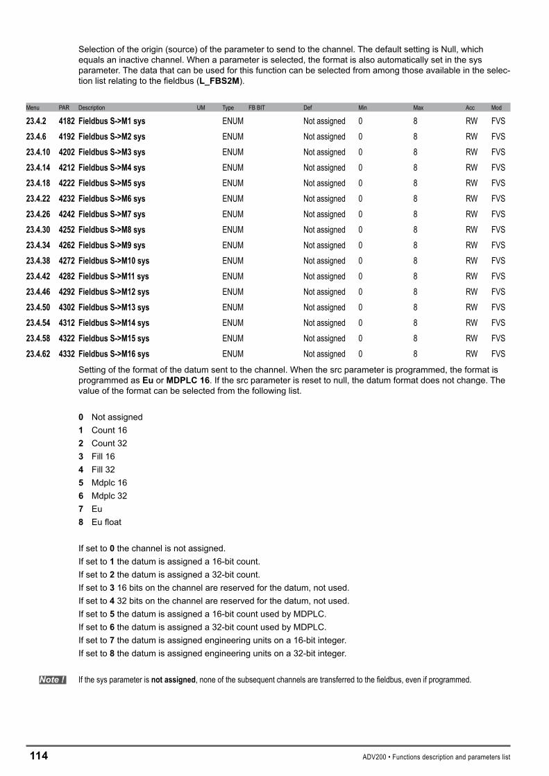
114 ADV200 • Functions description and parameters list
Selection of the origin (source) of the parameter to send to the channel. The default setting is Null, which equals an inactive channel. When a parameter is selected, the format is also automatically set in the sys parameter. The data that can be used for this function can be selected from among those available in the selec-tion list relating to the fieldbus (L_FBS�M).
Menu PAR Description UM Type FB BIT Def Min Max Acc Mod
23.4.2 4182 FieldbusS->M1sys ENUM Not assigned 0 8 RW FVS23.4.6 4192 FieldbusS->M2sys ENUM Not assigned 0 8 RW FVS23.4.10 4202 FieldbusS->M3sys ENUM Not assigned 0 8 RW FVS23.4.14 4212 FieldbusS->M4sys ENUM Not assigned 0 8 RW FVS23.4.18 4222 FieldbusS->M5sys ENUM Not assigned 0 8 RW FVS23.4.22 4232 FieldbusS->M6sys ENUM Not assigned 0 8 RW FVS23.4.26 4242 FieldbusS->M7sys ENUM Not assigned 0 8 RW FVS23.4.30 4252 FieldbusS->M8sys ENUM Not assigned 0 8 RW FVS23.4.34 4262 FieldbusS->M9sys ENUM Not assigned 0 8 RW FVS23.4.38 4272 FieldbusS->M10sys ENUM Not assigned 0 8 RW FVS23.4.42 4282 FieldbusS->M11sys ENUM Not assigned 0 8 RW FVS23.4.46 4292 FieldbusS->M12sys ENUM Not assigned 0 8 RW FVS23.4.50 4302 FieldbusS->M13sys ENUM Not assigned 0 8 RW FVS23.4.54 4312 FieldbusS->M14sys ENUM Not assigned 0 8 RW FVS23.4.58 4322 FieldbusS->M15sys ENUM Not assigned 0 8 RW FVS23.4.62 4332 FieldbusS->M16sys ENUM Not assigned 0 8 RW FVS
Setting of the format of the datum sent to the channel. When the src parameter is programmed, the format is programmed as Eu or MDPLC16. If the src parameter is reset to null, the datum format does not change. The value of the format can be selected from the following list. 0 Not assigned1 Count 16� Count 32� Fill 164 Fill 325 Mdplc 166 Mdplc 327 Eu� Eu float
If set to 0 the channel is not assigned.If set to 1 the datum is assigned a 16-bit count.If set to � the datum is assigned a 32-bit count.If set to� 16 bits on the channel are reserved for the datum, not used.If set to 4 32 bits on the channel are reserved for the datum, not used.If set to5 the datum is assigned a 16-bit count used by MDPLC.If set to 6 the datum is assigned a 32-bit count used by MDPLC.If set to 7 the datum is assigned engineering units on a 16-bit integer.If set to � the datum is assigned engineering units on a 32-bit integer.
Note ! If the sys parameter is notassigned, none of the subsequent channels are transferred to the fieldbus, even if programmed.

ADV200 • Functions description and parameters list 115
Menu PAR Description UM Type FB BIT Def Min Max Acc Mod
23.4.3 4184 DigFieldbusS->M1 INT32 32 0 0 0 ERW FVS23.4.7 4194 DigFieldbusS->M2 INT32 32 0 0 0 ERW FVS23.4.11 4204 DigFieldbusS->M3 INT32 32 0 0 0 ERW FVS23.4.15 4214 DigFieldbusS->M4 INT32 32 0 0 0 ERW FVS23.4.19 4224 DigFieldbusS->M5 INT32 32 0 0 0 ERW FVS23.4.23 4234 DigFieldbusS->M6 INT32 32 0 0 0 ERW FVS23.4.27 4244 DigFieldbusS->M7 INT32 32 0 0 0 ERW FVS23.4.31 4254 DigFieldbusS->M8 INT32 32 0 0 0 ERW FVS23.4.35 4264 DigFieldbusS->M9 INT32 32 0 0 0 ERW FVS23.4.39 4274 DigFieldbusS->M10 INT32 32 0 0 0 ERW FVS23.4.43 4284 DigFieldbusS->M11 INT32 32 0 0 0 ERW FVS23.4.47 4294 DigFieldbusS->M12 INT32 32 0 0 0 ERW FVS23.4.51 4304 DigFieldbusS->M13 INT32 32 0 0 0 ERW FVS23.4.55 4314 DigFieldbusS->M14 INT32 32 0 0 0 ERW FVS23.4.59 4324 DigFieldbusS->M15 INT32 32 0 0 0 ERW FVS23.4.63 4334 DigFieldbusS->M16 INT32 32 0 0 0 ERW FVS
If associated with the relative src, the value of this parameter is sent to the bus.
The user may modify the M->S and by S->M sys parameters. The consistency of the sys with the parameter assigned to the channel is checked.
Menu PAR Description UM Type FB BIT Def Min Max Acc Mod
23.4.4 4186 FieldbusS->M1mul FLOAT 1.0 1.0 1000.0 ERW FVS23.4.8 4196 FieldbusS->M2mul FLOAT 1.0 1.0 1000.0 ERW FVS23.4.12 4206 FieldbusS->M3mul FLOAT 1.0 1.0 1000.0 ERW FVS23.4.16 4216 FieldbusS->M4mul FLOAT 1.0 1.0 1000.0 ERW FVS23.4.20 4226 FieldbusS->M5mul FLOAT 1.0 1.0 1000.0 ERW FVS23.4.24 4236 FieldbusS->M6mul FLOAT 1.0 1.0 1000.0 ERW FVS23.4.28 4246 FieldbusS->M7mul FLOAT 1.0 1.0 1000.0 ERW FVS23.4.32 4256 FieldbusS->M8mul FLOAT 1.0 1.0 1000.0 ERW FVS23.4.36 4266 FieldbusS->M9mul FLOAT 1.0 1.0 1000.0 ERW FVS23.4.40 4276 FieldbusS->M10mul FLOAT 1.0 1.0 1000.0 ERW FVS23.4.44 4286 FieldbusS->M11mul FLOAT 1.0 1.0 1000.0 ERW FVS23.4.48 4296 FieldbusS->M12mul FLOAT 1.0 1.0 1000.0 ERW FVS23.4.52 4306 FieldbusS->M13mul FLOAT 1.0 1.0 1000.0 ERW FVS23.4.56 4316 FieldbusS->M14mul FLOAT 1.0 1.0 1000.0 ERW FVS23.4.60 4326 FieldbusS->M15mul FLOAT 1.0 1.0 1000.0 ERW FVS23.4.64 4336 FieldbusS->M16mul FLOAT 1.0 1.0 1000.0 ERW FVS
The “FieldbusS->Mxmul” parameters are multipliers that the drive applies to the datum before sending it to the bus. It is therefore possible to increase the resolution of some values read in EU and EU_float mode, also using decimal digits.N.B.: The drive does not check that the multiplied parameter expressed in bits fits in a 16-bit integer. You must make sure that the multiplier is compatible with the maximum value of the exchanged parameter and that it does not exceed the maximum size of 32768.
Example: FieldbusS->Mxmul = 10, S->M1 fieldbus par = Motorspeed, Sys S->M1 fieldbus = Eu. If the motor is running at 100 rpm, the PLC reads the value 100 * 10 = 1000 on the first word that is exchanged.

116 ADV200 • Functions description and parameters list
��.5–COMMUNICATION/WORDCOMP
Menu PAR Description UM Type FB BIT Def Min Max Acc Mod
23.5.1 4400 Wordbit0src LINK 16 6000 0 16384 ERW FVS23.5.2 4402 Wordbit1src LINK 16 6000 0 16384 ERW FVS23.5.3 4404 Wordbit2src LINK 16 6000 0 16384 ERW FVS23.5.4 4406 Wordbit3src LINK 16 6000 0 16384 ERW FVS23.5.5 4408 Wordbit4src LINK 16 6000 0 16384 ERW FVS23.5.6 4410 Wordbit5src LINK 16 6000 0 16384 ERW FVS23.5.7 4412 Wordbit6src LINK 16 6000 0 16384 ERW FVS23.5.8 4414 Wordbit7src LINK 16 6000 0 16384 ERW FVS23.5.9 4416 Wordbit8src LINK 16 6000 0 16384 ERW FVS23.5.10 4418 Wordbit9src LINK 16 6000 0 16384 ERW FVS23.5.11 4420 Wordbit10src LINK 16 6000 0 16384 ERW FVS23.5.12 4422 Wordbit11src LINK 16 6000 0 16384 ERW FVS23.5.13 4424 Wordbit12src LINK 16 6000 0 16384 ERW FVS23.5.14 4426 Wordbit13src LINK 16 6000 0 16384 ERW FVS23.5.15 4428 Wordbit14src LINK 16 6000 0 16384 ERW FVS23.5.16 4430 Wordbit15src LINK 16 6000 0 16384 ERW FVS
Selection of the origin (source) of the signal to be used for coding in Wordcomp. This function allows the user to compose a single word composed of 16 signals, each of which can be selected from among those listed in the “L_DIGSEL1” selection list.The values of the sectioned sizes are converted into a single word.
Word bit0 src
Word bit1 src
Word bit14 src
Word bit15 src
Word comp monWORD_0BIT_0
BIT_1
BIT_14
BIT_15
BIT_1
.........................
Menu PAR Description UM Type FB BIT Def Min Max Acc Mod
23.5.17 4432 Wordcompmon UINT32 16 0 0 0 ER FVSThe hexadecimal value of the Word comp output is displayed.
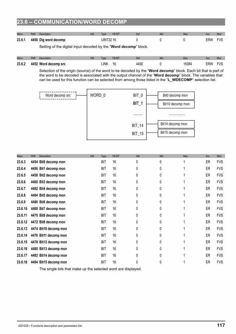
ADV200 • Functions description and parameters list 117
��.6–COMMUNICATION/WORDDECOMP
Menu PAR Description UM Type FB BIT Def Min Max Acc Mod
23.6.1 4450 Digworddecomp UINT32 16 0 0 0 ERW FVSSetting of the digital input decoded by the “Worddecomp” block.
Menu PAR Description UM Type FB BIT Def Min Max Acc Mod
23.6.2 4452 Worddecompsrc LINK 16 4450 0 16384 ERW FVSSelection of the origin (source) of the word to be decoded by the “Worddecomp” block. Each bit that is part of the word to be decoded is associated with the output channel of the “Worddecomp” block. The variables that can be used for this function can be selected from among those listed in the “L_WDECOMP” selection list.
Word decomp src Bit0 decomp monWORD_0 BIT_0
BIT_1
BIT_14
BIT_15
BIT_1
......... ................
Bit10 decomp mon
Bit14 decomp mon
Bit15 decomp mon
Menu PAR Description UM Type FB BIT Def Min Max Acc Mod
23.6.3 4454 Bit0decompmon BIT 16 0 0 1 ER FVS23.6.4 4456 Bit1decompmon BIT 16 0 0 1 ER FVS23.6.5 4458 Bit2decompmon BIT 16 0 0 1 ER FVS23.6.6 4460 Bit3decompmon BIT 16 0 0 1 ER FVS23.6.7 4462 Bit4decompmon BIT 16 0 0 1 ER FVS23.6.8 4464 Bit5decompmon BIT 16 0 0 1 ER FVS23.6.9 4466 Bit6decompmon BIT 16 0 0 1 ER FVS23.6.10 4468 Bit7decompmon BIT 16 0 0 1 ER FVS23.6.11 4470 Bit8decompmon BIT 16 0 0 1 ER FVS23.6.12 4472 Bit9decompmon BIT 16 0 0 1 ER FVS23.6.13 4474 Bit10decompmon BIT 16 0 0 1 ER FVS23.6.14 4476 Bit11decompmon BIT 16 0 0 1 ER FVS23.6.15 4478 Bit12decompmon BIT 16 0 0 1 ER FVS23.6.16 4480 Bit13decompmon BIT 16 0 0 1 ER FVS23.6.17 4482 Bit14decompmon BIT 16 0 0 1 ER FVS23.6.18 4484 Bit15decompmon BIT 16 0 0 1 ER FVS
The single bits that make up the selected word are displayed.
11� ADV200 • Functions description and parameters list
�4–ALARMCONFIG
In the ALARMCONFIG menu the type of effect any alarm signals have on the driveis determined:
- The alarm status is saved- How must the drive react to the alarm signal?- Auto restart- Alarm reset
For some alarms, behaviour can be configured separately for each signal, while for the others the Disabledriveis executed. Individual signals can also be sent to a programmable digital output.
Activity Ignore The alarm is not included in the list of alarms, it is not included in the alarm log, it is not signalled on the digital outputs, no drive commands are modified.
Warning The alarm is included in the list of alarms, it is included in the alarm log, it is signalled on the digital outputs, the First alarm information is updated, the Alarm enabled information is updated, no drive commands are modified.
Disable drive The alarm is included in the list of alarms, it is included in the alarm log, it is signalled on the digital outputs, the First alarm information is updated, the Alarm enabled information is updated, a command is sent to stop and disable the mo-tor, which stops due to inertia.
Stop The alarm is included in the list of alarms, it is included in the alarm log, it is signalled on the digital outputs, the First alarm information is updated, the Alarm enabled information is updated, a Stop command is sent. When the zero speed is reached the drive is disabled. If Ramp control mode is enabled, the drive moves to the zero speed with the set ramp time; when the Speeddelay0 sig-nal is activated the drive is disabled. If Speed control mode is enabled, the drive moves to the zero speed with the maximum current possible; when the Speeddelay0 signal is activated the drive is disabled. If Torque control mode is ena-bled, the drive moves to the zero speed with the time set by the load; when the Speeddelay0 signal is activated the drive is disabled.
Fast stop The alarm is included in the list of alarms, it is included in the alarm log, it is signalled on the digital outputs, the First alarm information is updated, the Alarm enabled information is updated, a Fast Stop command is sent. When the zero speed is reached the drive is disabled. If Ramp control mode is enabled, the drive moves to the zero speed with the set fast stop ramp time (decelera-tion time 3); when the Speeddelay0 signal is activated the drive is disabled. If Speed control mode is enabled, the drive moves to the zero speed with the maximum current possible; when the Speeddelay0 signal is activated the drive is disabled. If Torque control mode is enabled, the drive moves to the zero speed with the set load time; when the Speeddelay0 signal is activated the drive is disabled.
n alarms with Activity = Ignore or Warning can be enabled at the same time.If an alarm with Activity = Stop or Fast Stop is enabled and another alarm with an Activity other than Ignore or Warning is enabled, the drive stops and is disabled.

ADV200 • Functions description and parameters list 119
Not all alarms allow the controlled stopping of the drive. The following table shows the possibility of setting the Activi-ties for the individual alarm signals.
Alarm Ignore Warning Disabledrive Stop Faststop
ExtFlt ü ü ü ü ü
Motor OT ü ü ü ü ü
Overspeed ü ü ü ü ü
SpdRefLoss ü ü ü ü ü
SpdFbkLoss ü ü ü ü ü
Drive ovld ü ü ü ü ü
Motor ovld ü ü ü ü ü
Bres ovld ü ü ü ü ü
HTsens - - ü ü ü
InAir ü ü ü ü ü
Desat - - ü - -
IOverC - - ü - -
OverV - - ü - -
UnderV - - ü - -
PhLoss ü ü ü ü ü
GroundFault thr - - ü - -
Menu PAR Description UM Type FB BIT Def Min Max Acc Mod
24.1 4500 Faultresetsrc LINK 16 1120 0 16384 RW FVSSelection of the origin (source) of the signal to be used for the command to reset the drive after an alarm. The terminal that can be used for this function can be selected from among those listed in the “L_DIGSEL�” selec-tion list.
Menu PAR Description UM Type FB BIT Def Min Max Acc Mod
24.2 4502 ExtFltsrc LINK 16 6000 0 16384 RW FVSSelection of the origin (source) of the signal to be used as the input for the drive external fault alarm ExtFlt. The terminal that can be used for this function can be selected from among those listed in the “L_DIGSEL�” selection list.
Menu PAR Description UM Type FB BIT Def Min Max Acc Mod
24.3 4504 ExtFltactivity ENUM Disable 0 4 RW FVSSetting of the behaviour of the drive in the event of an external fault alarm ExtFlt. This alarm indicates the inter-vention of a drive external protection.
0 Ignore 1 Warning � Disable � Stop 4 Fast stop
Menu PAR Description UM Type FB BIT Def Min Max Acc Mod
24.4 4506 ExtFltrestart ENUM Disable 0 1 RW FVSEnabling of automatic restart after the external fault alarm ExtFlt
0 Disable 1 Enable
1�0 ADV200 • Functions description and parameters list
Menu PAR Description UM Type FB BIT Def Min Max Acc Mod
24.5 4508 ExtFltrestarttime ms UINT16 1000 120 30000 RW FVSSetting of the time within which the ExternalFaultalarm must be reset in order to perform automatic restart.
Menu PAR Description UM Type FB BIT Def Min Max Acc Mod
24.6 4510 ExtFltholdoff ms UINT16 0 0 10000 RW FVSSetting of the delay between the signalling of the external fault alarm ExtFlt and enabling of the alarm. If an alarm condition occurs, the drive will wait for the set time before blocking is enabled. If the alarm is removed within the set time, the drive will not indicate any alarm condition.
Menu PAR Description UM Type FB BIT Def Min Max Acc Mod
24.7 4520 MotorOTsrc LINK 16 6000 0 16384 RW FVSSelection of the origin (source) of the signal to be used for the motor overtemperature alarm MotorOT. The terminal that can be used for this function can be selected from among those listed in the “L_DIGSEL�” selec-tion list.
Menu PAR Description UM Type FB BIT Def Min Max Acc Mod
24.8 4522 MotorOTactivity ENUM Warning 0 4 RW FVSSetting of the behaviour of the drive in case of a motor overtemperature alarm MotorOT. This alarm indicates that the motor temperature is too high.
0 Ignore 1 Warning � Disable � Stop 4 Fast stop
Menu PAR Description UM Type FB BIT Def Min Max Acc Mod
24.9 4524 MotorOTrestart ENUM Disable 0 1 RW FVSEnabling of automatic restart after the motor overtemperature alarm MotorOT.
0 Disable 1 Enable
Menu PAR Description UM Type FB BIT Def Min Max Acc Mod
24.10 4526 TMotorOTrestarttime ms UINT16 1000 120 30000 RW FVSSetting of the time within which the MotorOvertemperaturealarm must be reset in order to perform automatic restart.
Menu PAR Description UM Type FB BIT Def Min Max Acc Mod
24.11 4528 MotorOTholdoff ms UINT16 1000 0 30000 RW FVSSetting of the delay between the signalling of the motor overtemperature alarm MotorOT and enabling of the alarm. If an alarm condition occurs, the drive will wait for the set time before enabling the alarm. If the alarm is removed within the set time, the drive will not indicate any alarm condition.
Menu PAR Description UM Type FB BIT Def Min Max Acc Mod
24.12 4540 Overspeedthreshold rpm INT16 CALCI 0 CALCI RW FVSSetting of the threshold above which the overspeed alarm Overspeed is enabled.

ADV200 • Functions description and parameters list 1�1
Menu PAR Description UM Type FB BIT Def Min Max Acc Mod
24.13 4542 Overspeedactivity ENUM Disable 0 4 RW FVSSetting of the behaviour of the drive in case of a motor overspeed alarm Overspeed. This alarm indicates that the motor speed has exceeded the threshold set in the Speedreftoplimand Speedrefbottomlim param-eters in the COMMANDS menu. 0 Ignore 1 Warning � Disable � Stop 4 Fast stop
Menu PAR Description UM Type FB BIT Def Min Max Acc Mod
24.14 4544 Overspeedholdoff ms UINT16 0 0 5000 RW FVSSetting of the delay between the signalling of the motor overspeed alarm Overspeed and enabling of the alarm. If an alarm condition occurs, the drive will wait for the set time before enabling the alarm. If the alarm is removed within the set time, the drive will not indicate any alarm condition.
Menu PAR Description UM Type FB BIT Def Min Max Acc Mod
24.15 4550 SpdRefLossthreshold rpm INT16 100 0 CALCI RW FVSSetting of the threshold below which the speed reference loss alarm SpdRefLoss occurs.
Menu PAR Description UM Type FB BIT Def Min Max Acc Mod
24.16 4552 SpdRefLossactivity ENUM Warning 0 4 RW FVSSetting of the behaviour of the drive in case of a speed reference loss alarm SpdRefLoss. This alarm indicates that the difference between the speed regulator reference and the actual motor speed is more than 100 rpm. This alarm must be disabled (= 0 Ignore) when parameter 556Controlmode is set to Torque (0) or when pa-rameter ��54 is set to a value other than zero.
0 Ignore 1 Warning � Disable � Stop 4 Fast stop
Menu PAR Description UM Type FB BIT Def Min Max Acc Mod
24.17 4554 SpdRefLossholdoff ms UINT16 1000 0 10000 RW FV_ Setting of the delay between the signalling of the speed reference loss alarm condition SpdRefLoss and ena-bling of the alarm. If an alarm condition occurs, the drive will wait for the set time before enabling the alarm. If the alarm is removed within the set time, the drive will not indicate any alarm condition.
Menu PAR Description UM Type FB BIT Def Min Max Acc Mod
24.18 4560 SpdFbkLossactivity ENUM Disable 0 4 RW FV_Setting of the behaviour of the drive in case of a speed feedback loss alarm SpdFbkLoss. This alarm indicates the loss of the encoder feedback signals.
0 Ignore 1 Warning � Disable � Stop 4 Fast stop
1�� ADV200 • Functions description and parameters list
Menu PAR Description UM Type FB BIT Def Min Max Acc Mod
24.19 4562 SpdFbkLossholdoff ms UINT16 200 0 10000 RW FVSSetting of the delay between the signalling of the speed feedback loss alarm condition SpdFbkLoss and the enabling of the alarm. If an alarm condition occurs, the drive will wait for the set time before enabling the alarm. If the alarm is removed within the set time, the drive will not indicate any alarm condition.
Menu PAR Description UM Type FB BIT Def Min Max Acc Mod
24.20 4570 Driveovldactivity ENUM Ignore 0 4 ERW FVSSetting of the behaviour of the drive in case of a drive overload alarm Driveovld. This alarm indicates that the drive overload threshold has been reached.
0 Ignore 1 Warning � Disable � Stop 4 Fast stop
Menu PAR Description UM Type FB BIT Def Min Max Acc Mod
24.21 4572 Motorovldactivity ENUM Warning 0 4 ERW FVSSetting of the behaviour of the drive in case of a motor overload alarm Motorovld. This alarm indicates that the motor overload threshold has been reached.
0 Ignore 1 Warning � Disable � Stop 4 Fast stop
Menu PAR Description UM Type FB BIT Def Min Max Acc Mod
24.22 4574 Bresovldactivity ENUM Disable 0 4 ERW FVSSetting of the behaviour of the drive in case of a braking resistor overload alarm Bresovld. This alarm indi-cates that the braking resistor overload threshold has been reached.
0 Ignore 1 Warning � Disable� Stop 4 Fast stop
Menu PAR Description UM Type FB BIT Def Min Max Acc Mod
24.23 4580 HTsensactivity ENUM Stop 2 4 ERW FVSSetting of the behaviour of the drive in case of a drive heatsink overtemperature alarm HTsens. This alarm indicates that the drive heatsink temperature is too high.
� Disable� Stop4 Fast stop
Menu PAR Description UM Type FB BIT Def Min Max Acc Mod
24.24 4582 HTsensrestart ENUM Disable 0 1 ERW FVSEnabling of automatic restart after the drive heatsink overtemperature alarm HTsens.
0 Disable 1 Enable

ADV200 • Functions description and parameters list 1��
Menu PAR Description UM Type FB BIT Def Min Max Acc Mod
24.25 4584 HTsensrestarttime ms UINT16 1000 120 30000 ERW FVSSetting of the time within which the HTsensoralarm must be reset in order to perform automatic restart.
Menu PAR Description UM Type FB BIT Def Min Max Acc Mod
24.26 4586 HTsensholdoff ms UINT16 1000 800 30000 ERW FVSSetting of the delay between the signalling of the drive heatsink overtemperature alarm HTsens and enabling of the alarm. If an alarm condition occurs, the drive will wait for the set time before enabling the alarm. If the alarm is removed within the set time, the drive will not indicate any alarm condition.
Menu PAR Description UM Type FB BIT Def Min Max Acc Mod
24.27 4600 InAiractivity ENUM Stop 0 4 ERW FVSSetting of the behaviour of the drive in case of an intake air overtemperature alarm InAir. This alarm indicates that the temperature of the intake cooling air is too high.
0 Ignore 1 Warning � Disable � Stop 4 Fast stop
Menu PAR Description UM Type FB BIT Def Min Max Acc Mod
24.28 4602 InAirrestart ENUM Disable 0 1 ERW FVSEnabling of automatic restart after the intake air overtemperature alarm InAir.
0 Disable 1 Enable
Menu PAR Description UM Type FB BIT Def Min Max Acc Mod
24.29 4604 InAirrestarttime ms UINT16 1000 120 30000 ERW FVSSetting of the time within which the HTsensoralarm must be reset in order to perform automatic restart.
Menu PAR Description UM Type FB BIT Def Min Max Acc Mod
24.30 4606 InAirholdoff ms UINT16 10000 0 30000 ERW FVSSetting of the delay between the signalling of the intake air overtemperature alarm InAir and enabling of the alarm. If an alarm condition occurs, the drive will wait for the set time before enabling the alarm. If the alarm is removed within the set time, the drive will not indicate any alarm condition.
Menu PAR Description UM Type FB BIT Def Min Max Acc Mod
24.31 4610 Desatrestart ENUM Disable 0 1 ERW FVSEnabling of automatic restart after the desaturation alarm Desat. This alarm indicates a short circuit between the motor phases or on the power bridge.
0 Disable 1 Enable
Menu PAR Description UM Type FB BIT Def Min Max Acc Mod
24.32 4612 Desatrestarttime ms UINT16 2000 1000 10000 ERW FVS
Setting of the time within which the Desaturation alarm must be reset in order to perform automatic restart. (Time with alarm signal active + 1000 msec).
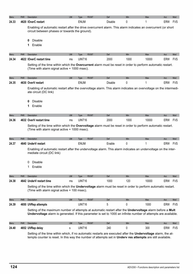
1�4 ADV200 • Functions description and parameters list
Menu PAR Description UM Type FB BIT Def Min Max Acc Mod
24.33 4620 IOverCrestart ENUM Disable 0 1 ERW FVSEnabling of automatic restart after the drive overcurrent alarm. This alarm indicates an overcurrent (or short circuit between phases or towards the ground).
0 Disable 1 Enable
Menu PAR Description UM Type FB BIT Def Min Max Acc Mod
24.34 4622 IOverCrestarttime ms UINT16 2000 1000 10000 ERW FVSSetting of the time within which the Overcurrent alarm must be reset in order to perform automatic restart. (Time with alarm signal active + 1000 msec).
Menu PAR Description UM Type FB BIT Def Min Max Acc Mod
24.35 4630 OverVrestart ENUM Disable 0 1 ERW FVSEnabling of automatic restart after the overvoltage alarm. This alarm indicates an overvoltage on the intermedi-ate circuit (DC link)
0 Disable 1 Enable
Menu PAR Description UM Type FB BIT Def Min Max Acc Mod
24.36 4632 OverVrestarttime ms UINT16 2000 1000 10000 ERW FVSSetting of the time within which the Overvoltage alarm must be reset in order to perform automatic restart. (Time with alarm signal active + 1000 msec).
Menu PAR Description UM Type FB BIT Def Min Max Acc Mod
24.37 4640 UnderVrestart ENUM Enable 0 1 ERW FVSEnabling of automatic restart after the undervoltage alarm. This alarm indicates an undervoltage on the inter-mediate circuit (DC link)
0 Disable 1 Enable
Menu PAR Description UM Type FB BIT Def Min Max Acc Mod
24.38 4642 UnderVrestarttime ms UINT16 1000 120 10000 ERW FVSSetting of the time within which the Undervoltage alarm must be reset in order to perform automatic restart. (Time with alarm signal active + 100 msec).
Menu PAR Description UM Type FB BIT Def Min Max Acc Mod
24.39 4650 UVRepattempts UINT16 5 0 1000 ERW FVSSetting of the maximum number of attempts at automatic restart after the Undervoltage alarm before a MultUndervoltage alarm is generated. If this parameter is set to 1000 an infinite number of attempts are available.
Menu PAR Description UM Type FB BIT Def Min Max Acc Mod
24.40 4652 UVRepdelay s UINT16 240 0 300 ERW FVSSetting of the time within which, if no automatic restarts are executed after the Undervoltage alarm, the at-tempts counter is reset. In this way the number of attempts set in Undervresattempts are still available.
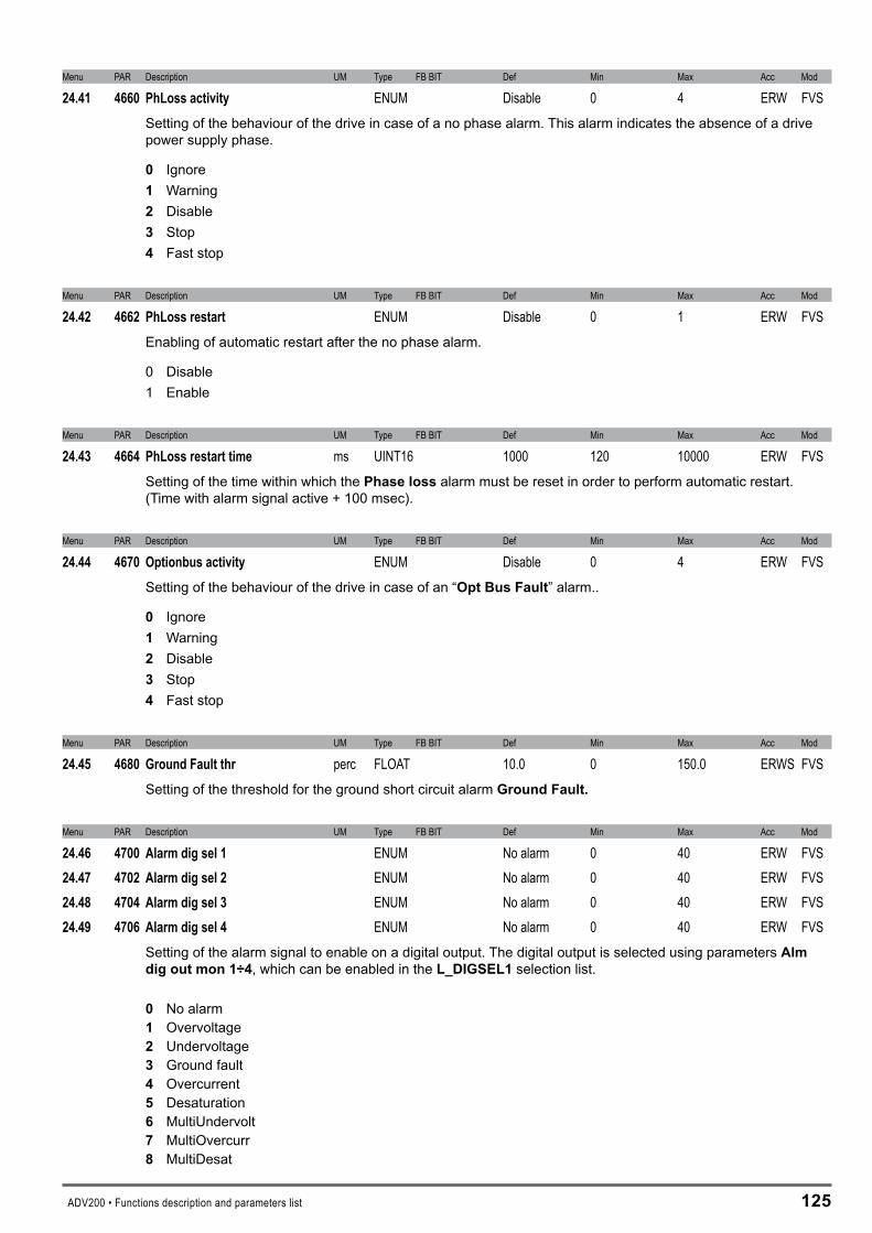
ADV200 • Functions description and parameters list 1�5
Menu PAR Description UM Type FB BIT Def Min Max Acc Mod
24.41 4660 PhLossactivity ENUM Disable 0 4 ERW FVSSetting of the behaviour of the drive in case of a no phase alarm. This alarm indicates the absence of a drive power supply phase.
0 Ignore 1 Warning � Disable � Stop 4 Fast stop
Menu PAR Description UM Type FB BIT Def Min Max Acc Mod
24.42 4662 PhLossrestart ENUM Disable 0 1 ERW FVSEnabling of automatic restart after the no phase alarm.
0 Disable 1 Enable
Menu PAR Description UM Type FB BIT Def Min Max Acc Mod
24.43 4664 PhLossrestarttime ms UINT16 1000 120 10000 ERW FVSSetting of the time within which the Phaselossalarm must be reset in order to perform automatic restart. (Time with alarm signal active + 100 msec).
Menu PAR Description UM Type FB BIT Def Min Max Acc Mod
24.44 4670 Optionbusactivity ENUM Disable 0 4 ERW FVSSetting of the behaviour of the drive in case of an “OptBusFault” alarm..
0 Ignore1 Warning� Disable� Stop 4 Fast stop
Menu PAR Description UM Type FB BIT Def Min Max Acc Mod
24.45 4680 GroundFaultthr perc FLOAT 10.0 0 150.0 ERWS FVSSetting of the threshold for the ground short circuit alarm GroundFault.
Menu PAR Description UM Type FB BIT Def Min Max Acc Mod
24.46 4700 Alarmdigsel1 ENUM No alarm 0 40 ERW FVS24.47 4702 Alarmdigsel2 ENUM No alarm 0 40 ERW FVS24.48 4704 Alarmdigsel3 ENUM No alarm 0 40 ERW FVS24.49 4706 Alarmdigsel4 ENUM No alarm 0 40 ERW FVS
Setting of the alarm signal to enable on a digital output. The digital output is selected using parameters Almdigoutmon1÷4, which can be enabled in the L_DIGSEL1 selection list.
0 No alarm1 Overvoltage� Undervoltage� Ground fault4 Overcurrent5 Desaturation6 MultiUndervolt7 MultiOvercurr� MultiDesat

1�6 ADV200 • Functions description and parameters list
9 Heatsink OT10 HeatsinkS OTUT11 Intakeair OT1� Motor OT1� Drive overload14 Motor overload15 Bres overload16 Phaseloss17 Opt Bus fault1� Opt 1 IO fault19 Opt 2 IO fault�0 Opt Enc fault�1 External fault�� Speed fbk loss�� Overspeed�4 Speed ref loss�5 Emg stop alarm�6 Power down�7 Not Used1�� Not Used2�9 Not Used3�0 Not Used4�1 Not Used5�� Not Used6�� Plc1 fault�4 Plc2 fault�5 Plc3 fault�6 Plc4 fault�7 Plc5 fault�� Plc6 fault�9 Plc7 fault40 Plc8 fault41 Watchdog4� Trap error4� System error44 User error45 Param error46 Load def par47 Plc cfg error4� Load def plc49 Key failed
Menu PAR Description UM Type FB BIT Def Min Max Acc Mod
24.50 4720 Almautoresettime s FLOAT 0 0 60.0 ERW FVSSetting of the time interval that must pass before executing an automatic reset.If no alarms are enabled the drive is set to restart.If some alarms are still enabled the drive is set to execute a new attempt at automatic reset.At each attempted reset a counter increases. If the limit set in the Alm autoreset number parameter is reached the drive is set to make no more attempts at reset and waits for a user reset.The counter is set to zero when an automatic reset or user reset is performed and no alarms are enabled.If the parameter is 0 the function is disabled.
Menu PAR Description UM Type FB BIT Def Min Max Acc Mod
24.51 4722 Almautoresetnumber UINT16 20 0 100 ERW FVSSetting of the maximum number of attempted automatic resets.

ADV200 • Functions description and parameters list 1�7
�5–ALARMLOG
This is the menu in which the log of previous alarms is saved, with the time the alarm occurred (in relation to the Timedrivepoweron parameter). The alarms are displayed starting from the most recent (No. 1) up to the furthest back in time (No. 30). Up to 30 alarm signals can be displayed. The sub-code is used by service technicians to identify the specific type of alarm. Press the ▲ and ▼ keys to scroll the screen pages of the alarm log. The alarm log cannot be deleted.
3 SpdFbkLoss
4 Overspeed110:20 0000H
109:25 0000H
T+ T- EN LOC Ilim n=0 AL
1 PhaseLoss
2 Undervoltage110:32 0000H
110:25 0000H
T+ T- EN LOC Ilim n=0 AL
Alarm description
Sub-code
Alarm number
Time alarmoccurred

1�� ADV200 • Functions description and parameters list
�6–APPLICATION
This menu is designed to host two applications (e.g. PID control, etc.) using the MDPlc program, currently in progress. It will not be possible to use both applications simultaneously. The 55�Applicationselectparameter in the DRIVE CONFIG menu must be used to select between the two possible applications.
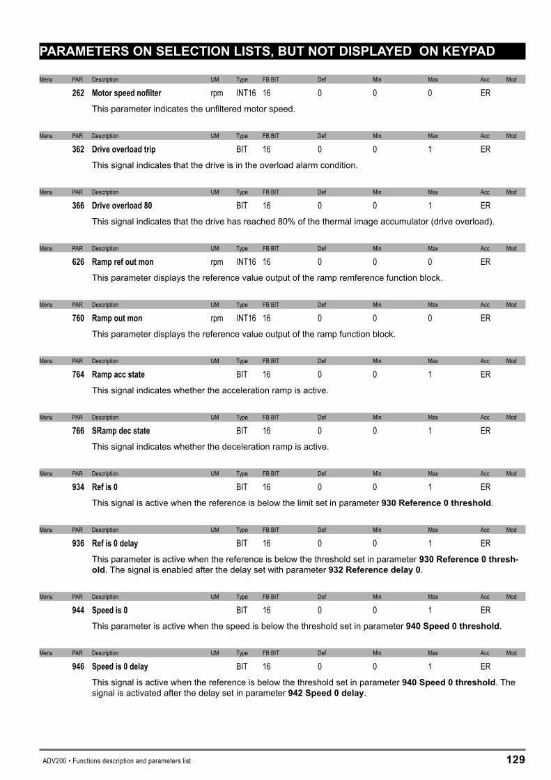
ADV200 • Functions description and parameters list 1�9
PARAMETERSONSELECTIONLISTS,BUTNOTDISPLAYEDONKEYPAD
Menu PAR Description UM Type FB BIT Def Min Max Acc Mod
262 Motorspeednofilter rpm INT16 16 0 0 0 ER This parameter indicates the unfiltered motor speed.
Menu PAR Description UM Type FB BIT Def Min Max Acc Mod
362 Driveoverloadtrip BIT 16 0 0 1 ER This signal indicates that the drive is in the overload alarm condition.
Menu PAR Description UM Type FB BIT Def Min Max Acc Mod
366 Driveoverload80 BIT 16 0 0 1 ER This signal indicates that the drive has reached 80% of the thermal image accumulator (drive overload).
Menu PAR Description UM Type FB BIT Def Min Max Acc Mod
626 Ramprefoutmon rpm INT16 16 0 0 0 ER This parameter displays the reference value output of the ramp remference function block.
Menu PAR Description UM Type FB BIT Def Min Max Acc Mod
760 Rampoutmon rpm INT16 16 0 0 0 ER This parameter displays the reference value output of the ramp function block.
Menu PAR Description UM Type FB BIT Def Min Max Acc Mod
764 Rampaccstate BIT 16 0 0 1 ER This signal indicates whether the acceleration ramp is active.
Menu PAR Description UM Type FB BIT Def Min Max Acc Mod
766 SRampdecstate BIT 16 0 0 1 ER This signal indicates whether the deceleration ramp is active.
Menu PAR Description UM Type FB BIT Def Min Max Acc Mod
934 Refis0 BIT 16 0 0 1 ER This signal is active when the reference is below the limit set in parameter 9�0Reference0threshold.
Menu PAR Description UM Type FB BIT Def Min Max Acc Mod
936 Refis0delay BIT 16 0 0 1 ER This parameter is active when the reference is below the threshold set in parameter 9�0Reference0thresh-old. The signal is enabled after the delay set with parameter9��Referencedelay0.
Menu PAR Description UM Type FB BIT Def Min Max Acc Mod
944 Speedis0 BIT 16 0 0 1 ER This parameter is active when the speed is below the threshold set in parameter 940Speed0threshold.
Menu PAR Description UM Type FB BIT Def Min Max Acc Mod
946 Speedis0delay BIT 16 0 0 1 ER This signal is active when the reference is below the threshold set in parameter940Speed0threshold. The signal is activated after the delay set in parameter 94�Speed0delay.
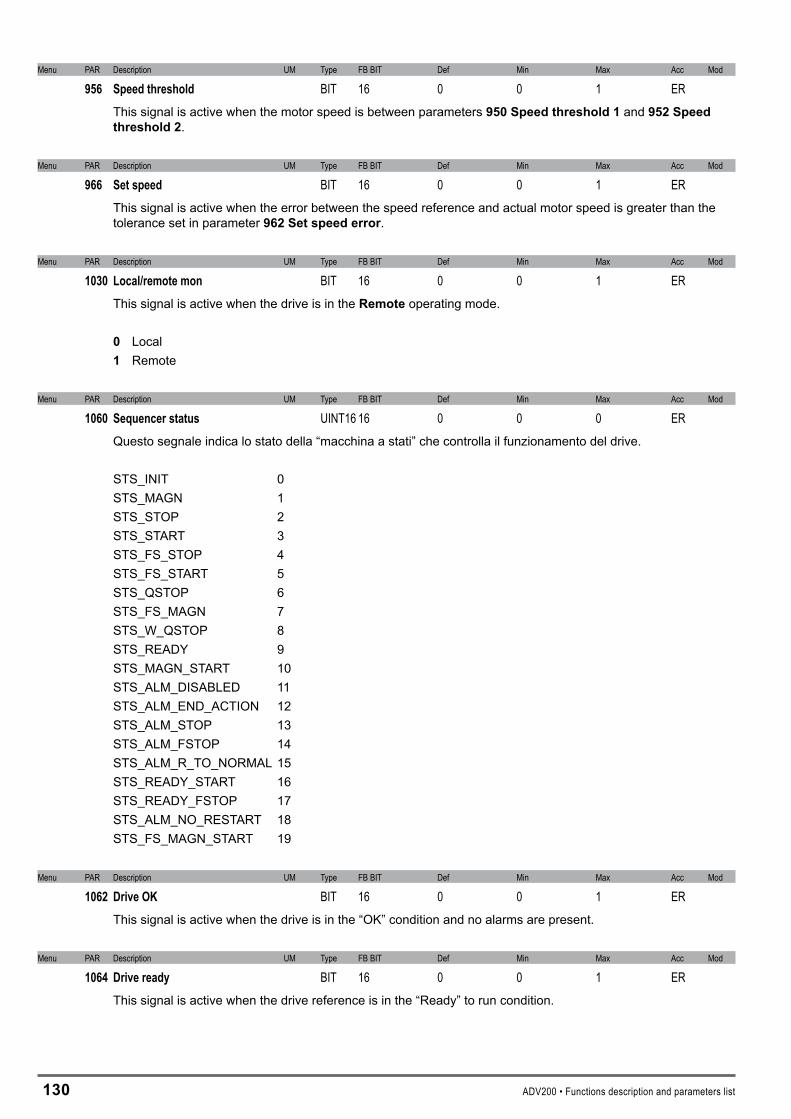
1�0 ADV200 • Functions description and parameters list
Menu PAR Description UM Type FB BIT Def Min Max Acc Mod
956 Speedthreshold BIT 16 0 0 1 ER This signal is active when the motor speed is between parameters 950Speedthreshold1 and 95�Speedthreshold�.
Menu PAR Description UM Type FB BIT Def Min Max Acc Mod
966 Setspeed BIT 16 0 0 1 ER This signal is active when the error between the speed reference and actual motor speed is greater than the tolerance set in parameter 96�Setspeederror.
Menu PAR Description UM Type FB BIT Def Min Max Acc Mod
1030 Local/remotemon BIT 16 0 0 1 ER This signal is active when the drive is in the Remote operating mode.
0 Local1 Remote
Menu PAR Description UM Type FB BIT Def Min Max Acc Mod
1060 Sequencerstatus UINT16 16 0 0 0 ER Questo segnale indica lo stato della “macchina a stati” che controlla il funzionamento del drive.
STS_INIT 0STS_MAGN 1STS_STOP 2STS_START 3STS_FS_STOP 4STS_FS_START 5STS_QSTOP 6STS_FS_MAGN 7STS_W_QSTOP 8STS_READY 9STS_MAGN_START 10STS_ALM_DISABLED 11STS_ALM_END_ACTION 12STS_ALM_STOP 13STS_ALM_FSTOP 14STS_ALM_R_TO_NORMAL 15STS_READY_START 16STS_READY_FSTOP 17STS_ALM_NO_RESTART 18STS_FS_MAGN_START 19
Menu PAR Description UM Type FB BIT Def Min Max Acc Mod
1062 DriveOK BIT 16 0 0 1 ER This signal is active when the drive is in the “OK” condition and no alarms are present.
Menu PAR Description UM Type FB BIT Def Min Max Acc Mod
1064 Driveready BIT 16 0 0 1 ER This signal is active when the drive reference is in the “Ready” to run condition.
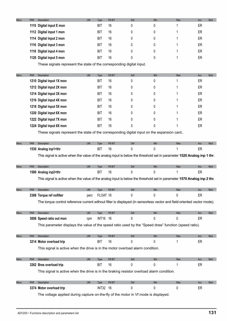
ADV200 • Functions description and parameters list 1�1
Menu PAR Description UM Type FB BIT Def Min Max Acc Mod
1110 DigitalinputEmon BIT 16 0 0 1 ER 1112 Digitalinput1mon BIT 16 0 0 1 ER 1114 Digitalinput2mon BIT 16 0 0 1 ER 1116 Digitalinput3mon BIT 16 0 0 1 ER 1118 Digitalinput4mon BIT 16 0 0 1 ER 1120 Digitalinput5mon BIT 16 0 0 1 ER
These signals represent the state of the corresponding digital input.
Menu PAR Description UM Type FB BIT Def Min Max Acc Mod
1210 Digitalinput1Xmon BIT 16 0 0 1 ER 1212 Digitalinput2Xmon BIT 16 0 0 1 ER 1214 Digitalinput3Xmon BIT 16 0 0 1 ER 1216 Digitalinput4Xmon BIT 16 0 0 1 ER 1218 Digitalinput5Xmon BIT 16 0 0 1 ER 1220 Digitalinput6Xmon BIT 16 0 0 1 ER 1222 Digitalinput7Xmon BIT 16 0 0 1 ER 1224 Digitalinput8Xmon BIT 16 0 0 1 ER
These signals represent the state of the corresponding digital input on the expansion card..
Menu PAR Description UM Type FB BIT Def Min Max Acc Mod
1530 Analoginp1<thr BIT 16 0 0 1 ER This signal is active when the value of the analog input is below the threshold set in parameter 15�0Analoginp1thr.
Menu PAR Description UM Type FB BIT Def Min Max Acc Mod
1580 Analoginp2<thr BIT 16 0 0 1 ER This signal is active when the value of the analog input is below the threshold set in parameter 1570Analoginp�thr.
Menu PAR Description UM Type FB BIT Def Min Max Acc Mod
2388 Torquerefnofilter perc FLOAT 16 0 0 0 ER The torque control reference current without filter is displayed (in sensorless vector and field-oriented vector mode).
Menu PAR Description UM Type FB BIT Def Min Max Acc Mod
3006 Speedratiooutmon rpm INT16 16 0 0 0 ER This parameter displays the value of the speed ratio used by the “Speed draw” function (speed ratio).
Menu PAR Description UM Type FB BIT Def Min Max Acc Mod
3214 Motoroverloadtrip BIT 16 0 0 1 ER This signal is active when the drive is in the motor overload alarm condition.
Menu PAR Description UM Type FB BIT Def Min Max Acc Mod
3262 Bresoverloadtrip BIT 16 0 0 1 ER This signal is active when the drive is in the braking resistor overload alarm condition.
Menu PAR Description UM Type FB BIT Def Min Max Acc Mod
3374 Motoroverloadtrip INT32 16 0 0 0 ER The voltage applied during capture on-the-fly of the motor in Vf mode is displayed.
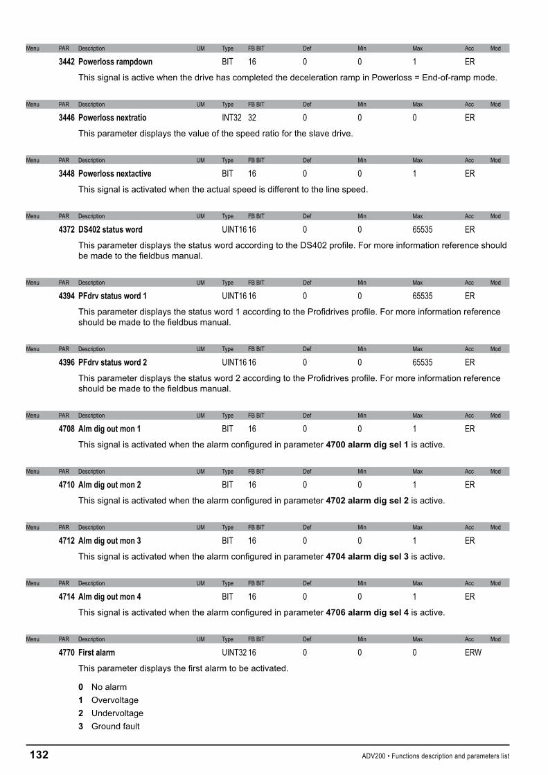
1�� ADV200 • Functions description and parameters list
Menu PAR Description UM Type FB BIT Def Min Max Acc Mod
3442 Powerlossrampdown BIT 16 0 0 1 ER This signal is active when the drive has completed the deceleration ramp in Powerloss = End-of-ramp mode.
Menu PAR Description UM Type FB BIT Def Min Max Acc Mod
3446 Powerlossnextratio INT32 32 0 0 0 ER This parameter displays the value of the speed ratio for the slave drive.
Menu PAR Description UM Type FB BIT Def Min Max Acc Mod
3448 Powerlossnextactive BIT 16 0 0 1 ER This signal is activated when the actual speed is different to the line speed.
Menu PAR Description UM Type FB BIT Def Min Max Acc Mod
4372 DS402statusword UINT16 16 0 0 65535 ERThis parameter displays the status word according to the DS402 profile. For more information reference should be made to the fieldbus manual.
Menu PAR Description UM Type FB BIT Def Min Max Acc Mod
4394 PFdrvstatusword1 UINT16 16 0 0 65535 ERThis parameter displays the status word 1 according to the Profidrives profile. For more information reference should be made to the fieldbus manual.
Menu PAR Description UM Type FB BIT Def Min Max Acc Mod
4396 PFdrvstatusword2 UINT16 16 0 0 65535 ERThis parameter displays the status word 2 according to the Profidrives profile. For more information reference should be made to the fieldbus manual.
Menu PAR Description UM Type FB BIT Def Min Max Acc Mod
4708 Almdigoutmon1 BIT 16 0 0 1 ER This signal is activated when the alarm configured in parameter 4700alarmdigsel1 is active.
Menu PAR Description UM Type FB BIT Def Min Max Acc Mod
4710 Almdigoutmon2 BIT 16 0 0 1 ER This signal is activated when the alarm configured in parameter 470�alarmdigsel� is active.
Menu PAR Description UM Type FB BIT Def Min Max Acc Mod
4712 Almdigoutmon3 BIT 16 0 0 1 ER This signal is activated when the alarm configured in parameter 4704alarmdigsel�is active.
Menu PAR Description UM Type FB BIT Def Min Max Acc Mod
4714 Almdigoutmon4 BIT 16 0 0 1 ER This signal is activated when the alarm configured in parameter 4706alarmdigsel4 is active.
Menu PAR Description UM Type FB BIT Def Min Max Acc Mod
4770 Firstalarm UINT32 16 0 0 0 ERW This parameter displays the first alarm to be activated.
0 No alarm 1 Overvoltage� Undervoltage� Ground fault
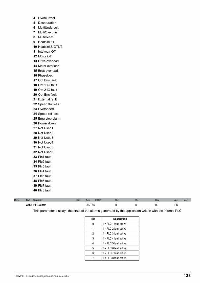
ADV200 • Functions description and parameters list 1��
4 Overcurrent5 Desaturation6 MultiUndervolt7 MultiOvercurr� MultiDesat9 Heatsink OT10 HeatsinkS OTUT11 Intakeair OT1� Motor OT1� Drive overload14 Motor overload15 Bres overload16 Phaseloss17 Opt Bus fault1� Opt 1 IO fault19 Opt 2 IO fault�0 Opt Enc fault�1 External fault�� Speed fbk loss�� Overspeed�4 Speed ref loss�5 Emg stop alarm�6 Power down�7 Not Used1�� Not Used2�9 Not Used3�0 Not Used4�1 Not Used5�� Not Used6�� Plc1 fault�4 Plc2 fault�5 Plc3 fault�6 Plc4 fault�7 Plc5 fault�� Plc6 fault�9 Plc7 fault40 Plc8 fault
Menu PAR Description UM Type FB BIT Def Min Max Acc Mod
4780 PLCalarm UINT16 0 0 0 ER This parameter displays the state of the alarms generated by the application written with the internal PLC
Bit Description0 1 = PLC 1 fault active 1 1 = PLC 2 fault active2 1 = PLC 3 fault active3 1 = PLC 4 fault active4 1 = PLC 5 fault active5 1 = PLC 6 fault active6 1 = PLC 7 fault active7 1 = PLC 8 fault active
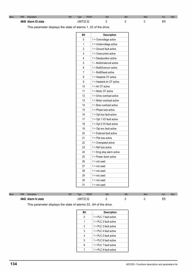
1�4 ADV200 • Functions description and parameters list
Menu PAR Description UM Type FB BIT Def Min Max Acc Mod
4840 AlarmlOstate UINT32 32 0 0 0 ERThis parameter displays the state of alarms 1..32 of the drive.
Bit Description0 1 = Overvoltage active1 1 = Undervoltage active2 1 = Ground fault active3 1 = Overcurrent active4 1 = Desaturation active5 1 – MultiUndervolt active6 1 = MultiOvercurr active7 1 – MultiDesat active8 1 = Heatsink OT active9 1 = Heatsink lin OT active
10 1 = Air OT active11 1 = Motor OT active12 1 = Drive overload active13 1 = Motor overload active14 1 = Bres overload active15 1 = Phase loss active16 1 = Opt bus fault active17 1 = Opt 1 I/O fault active18 1 = Opt 2 I/O fault active19 1 = Opt enc fault active20 1 = External fault active21 1 = Fbk loss active22 1 = Overspeed active23 1 = Ref loss active24 1 = Emg stop alarm active25 1 = Power down active26 1 = not used27 1 = not used28 1 = not used29 1 = not used30 1 = not used31 1 = not used
Menu PAR Description UM Type FB BIT Def Min Max Acc Mod
4842 Alarmhistate UINT32 32 0 0 0 ERThis parameter displays the state of alarms 33...64 of the drive.
Bit Description0 1 = PLC 1 fault active 1 1 = PLC 2 fault active2 1 = PLC 3 fault active3 1 = PLC 4 fault active4 1 = PLC 5 fault active5 1 = PLC 6 fault active6 1 = PLC 7 fault active7 1 = PLC 8 fault active

ADV200 • Functions description and parameters list 1�5
Menu PAR Description UM Type FB BIT Def Min Max Acc Mod
6000 Null UINT32 32 0 0 0 ER This signal forces the variable to the zero level (always disabled).
Menu PAR Description UM Type FB BIT Def Min Max Acc Mod
6002 One UINT32 32 1 1 1 ER This signal forces the variable to level one (always active).
Menu PAR Description UM Type FB BIT Def Min Max Acc Mod
6004 Speedlimitstate BIT 16 0 0 1 ER This signal is activated when the drive is in the speed limit condition.
Menu PAR Description UM Type FB BIT Def Min Max Acc Mod
6006 Currentlimitstate BIT 16 0 0 1 ER This signal is activated when the drive is in the current limit condition.
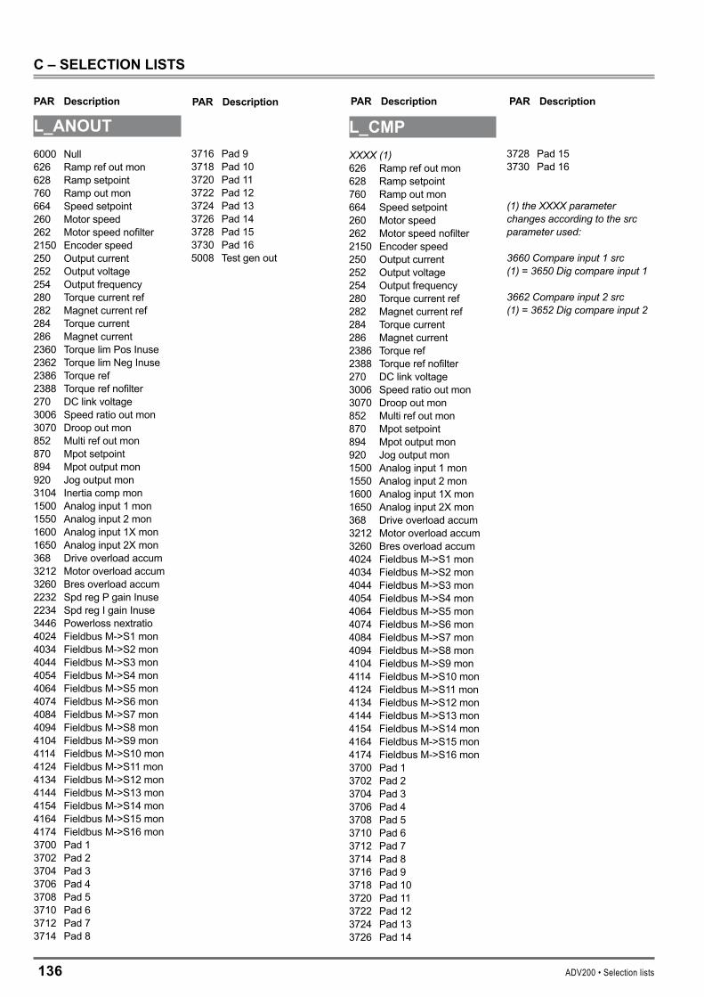
1�6 ADV200 • Selection lists
PAR Description PAR Description PAR Description PAR Description
C–SELECTIONLISTS
L_ANOUT6000 Null626 Ramp ref out mon628 Ramp setpoint760 Ramp out mon664 Speed setpoint260 Motor speed262 Motor speed nofilter2150 Encoder speed250 Output current252 Output voltage254 Output frequency280 Torque current ref282 Magnet current ref284 Torque current286 Magnet current2360 Torque lim Pos Inuse2362 Torque lim Neg Inuse2386 Torque ref2388 Torque ref nofilter270 DC link voltage3006 Speed ratio out mon3070 Droop out mon852 Multi ref out mon870 Mpot setpoint894 Mpot output mon920 Jog output mon3104 Inertia comp mon1500 Analog input 1 mon1550 Analog input 2 mon1600 Analog input 1X mon1650 Analog input 2X mon368 Drive overload accum3212 Motor overload accum3260 Bres overload accum2232 Spd reg P gain Inuse2234 Spd reg I gain Inuse3446 Powerloss nextratio4024 Fieldbus M->S1 mon4034 Fieldbus M->S2 mon4044 Fieldbus M->S3 mon4054 Fieldbus M->S4 mon4064 Fieldbus M->S5 mon4074 Fieldbus M->S6 mon4084 Fieldbus M->S7 mon4094 Fieldbus M->S8 mon4104 Fieldbus M->S9 mon4114 Fieldbus M->S10 mon4124 Fieldbus M->S11 mon4134 Fieldbus M->S12 mon4144 Fieldbus M->S13 mon4154 Fieldbus M->S14 mon4164 Fieldbus M->S15 mon4174 Fieldbus M->S16 mon3700 Pad 13702 Pad 23704 Pad 33706 Pad 43708 Pad 53710 Pad 63712 Pad 73714 Pad 8
3716 Pad 93718 Pad 103720 Pad 113722 Pad 123724 Pad 133726 Pad 143728 Pad 153730 Pad 165008 Test gen out
L_CMPXXXX (1)626 Ramp ref out mon628 Ramp setpoint760 Ramp out mon664 Speed setpoint260 Motor speed262 Motor speed nofilter2150 Encoder speed250 Output current252 Output voltage254 Output frequency280 Torque current ref282 Magnet current ref284 Torque current286 Magnet current2386 Torque ref2388 Torque ref nofilter270 DC link voltage3006 Speed ratio out mon3070 Droop out mon852 Multi ref out mon870 Mpot setpoint894 Mpot output mon920 Jog output mon1500 Analog input 1 mon1550 Analog input 2 mon1600 Analog input 1X mon1650 Analog input 2X mon368 Drive overload accum3212 Motor overload accum3260 Bres overload accum4024 Fieldbus M->S1 mon4034 Fieldbus M->S2 mon4044 Fieldbus M->S3 mon4054 Fieldbus M->S4 mon4064 Fieldbus M->S5 mon4074 Fieldbus M->S6 mon4084 Fieldbus M->S7 mon4094 Fieldbus M->S8 mon4104 Fieldbus M->S9 mon4114 Fieldbus M->S10 mon4124 Fieldbus M->S11 mon4134 Fieldbus M->S12 mon4144 Fieldbus M->S13 mon4154 Fieldbus M->S14 mon4164 Fieldbus M->S15 mon4174 Fieldbus M->S16 mon3700 Pad 13702 Pad 23704 Pad 33706 Pad 43708 Pad 53710 Pad 63712 Pad 73714 Pad 83716 Pad 93718 Pad 103720 Pad 113722 Pad 123724 Pad 133726 Pad 14
3728 Pad 153730 Pad 16
(1) the XXXX parameter changes according to the src parameter used:
3660 Compare input 1 src (1) = 3650 Dig compare input 1
3662 Compare input 2 src (1) = 3652 Dig compare input 2

ADV200 • Selection lists 1�7
PAR Description PAR Description PAR Description PAR Description
L_DIGSEL16000 Null6002 One1110 Digital input E mon1112 Digital input 1 mon1114 Digital input 2 mon1116 Digital input 3 mon1118 Digital input 4 mon1120 Digital input 5 mon1210 Digital input 1X mon1212 Digital input 2X mon1214 Digital input 3X mon1216 Digital input 4X mon1218 Digital input 5X mon1220 Digital input 6X mon1222 Digital input 7X mon1224 Digital input 8X mon1062 Drive OK1064 Drive ready934 Ref is 0936 Ref is 0 delay944 Speed is 0946 Speed is 0 delay956 Speed threshold966 Set speed1066 Enable state mon1068 Start state mon1070 FastStop state mon1024 Enable cmd mon1026 Start cmd mon1028 FastStop cmd mon4708 Alm dig out mon 14710 Alm dig out mon 24712 Alm dig out mon 34714 Alm dig out mon 41530 Analog inp1<thr1580 Analog inp2<thr362 Drive overload trip3214 Motor overload trip3262 Bres overload trip366 Drive overload 801048 FR start mon1050 FR reverse mon4454 Bit0 decomp mon4456 Bit1 decomp mon4458 Bit2 decomp mon4460 Bit3 decomp mon4462 Bit4 decomp mon4464 Bit5 decomp mon4466 Bit6 decomp mon4468 Bit7 decomp mon4470 Bit8 decomp mon4472 Bit9 decomp mon4474 Bit10 decomp mon4476 Bit11 decomp mon4478 Bit12 decomp mon4480 Bit13 decomp mon4482 Bit14 decomp mon4484 Bit15 decomp mon3700 Pad 13702 Pad 23704 Pad 3
3706 Pad 43708 Pad 53710 Pad 63712 Pad 73714 Pad 83716 Pad 93718 Pad 103720 Pad 113722 Pad 123724 Pad 133726 Pad 143728 Pad 153730 Pad 166004 Speed limit state6006 Current limit state764 Ramp acc state766 Ramp dec state1030 Local/remote mon4780 Alarm PLC3676 Compare output3442 Powerloss rampdown3448 Powerloss nextactive
L_DIGSEL�6000 Null6002 One1110 Digital input E mon1112 Digital input 1 mon1114 Digital input 2 mon1116 Digital input 3 mon1118 Digital input 4 mon1120 Digital input 5 mon1210 Digital input 1X mon1212 Digital input 2X mon1214 Digital input 3X mon1216 Digital input 4X mon1218 Digital input 5X mon1220 Digital input 6X mon1222 Digital input 7X mon1224 Digital input 8X mon4454 Bit0 decomp mon4456 Bit1 decomp mon4458 Bit2 decomp mon4460 Bit3 decomp mon4462 Bit4 decomp mon4464 Bit5 decomp mon4466 Bit6 decomp mon4468 Bit7 decomp mon4470 Bit8 decomp mon4472 Bit9 decomp mon4474 Bit10 decomp mon4476 Bit11 decomp mon4478 Bit12 decomp mon4480 Bit13 decomp mon4482 Bit14 decomp mon4484 Bit15 decomp mon3700 Pad 13702 Pad 23704 Pad 33706 Pad 43708 Pad 53710 Pad 63712 Pad 73714 Pad 83716 Pad 93718 Pad 103720 Pad 113722 Pad 123724 Pad 133726 Pad 143728 Pad 153730 Pad 161530 Analog inp1<thr1580 Analog inp2<thr1048 FR start mon1050 FR reverse mon3676 Compare output
L_DIGSEL�XXXX (2)6000 Null6002 One1110 Digital input E mon1112 Digital input 1 mon1114 Digital input 2 mon1116 Digital input 3 mon1118 Digital input 4 mon1120 Digital input 5 mon1210 Digital input 1X mon1212 Digital input 2X mon1214 Digital input 3X mon1216 Digital input 4X mon1218 Digital input 5X mon1220 Digital input 6X mon1222 Digital input 7X mon1224 Digital input 8X mon1062 Drive OK1064 Drive ready934 Ref is 0936 Ref is 0 delay944 Speed is 0946 Speed is 0 delay954 Speed threshold dly966 Set speed1066 Enable state mon1068 Start state mon1070 FastStop state mon1024 Enable cmd mon1026 Start cmd mon1028 FastStop cmd mon4708 Alm dig out mon 14710 Alm dig out mon 24712 Alm dig out mon 34714 Alm dig out mon 41530 Analog inp1<thr1580 Analog inp2<thr362 Drive overload trip3214 Motor overload trip3262 Bres overload trip366 Drive overload 801048 FR start mon1050 FR reverse mon4454 Bit0 decomp mon4456 Bit1 decomp mon4458 Bit2 decomp mon4460 Bit3 decomp mon4462 Bit4 decomp mon4464 Bit5 decomp mon4466 Bit6 decomp mon4468 Bit7 decomp mon4470 Bit8 decomp mon4472 Bit9 decomp mon4474 Bit10 decomp mon4476 Bit11 decomp mon4478 Bit12 decomp mon4480 Bit13 decomp mon4482 Bit14 decomp mon4484 Bit15 decomp mon3700 Pad 13702 Pad 2
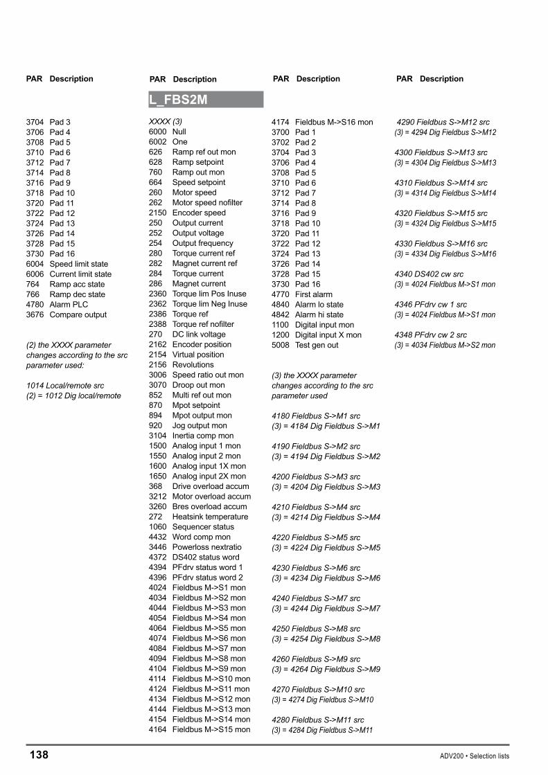
1�� ADV200 • Selection lists
PAR Description PAR Description PAR Description PAR Description
3704 Pad 33706 Pad 43708 Pad 53710 Pad 63712 Pad 73714 Pad 83716 Pad 93718 Pad 103720 Pad 113722 Pad 123724 Pad 133726 Pad 143728 Pad 153730 Pad 166004 Speed limit state6006 Current limit state764 Ramp acc state766 Ramp dec state4780 Alarm PLC3676 Compare output
(2) the XXXX parameter changes according to the src parameter used:
1014 Local/remote src (2) = 1012 Dig local/remote
L_FBS�MXXXX (3)6000 Null6002 One626 Ramp ref out mon628 Ramp setpoint760 Ramp out mon664 Speed setpoint260 Motor speed262 Motor speed nofilter2150 Encoder speed250 Output current252 Output voltage254 Output frequency280 Torque current ref282 Magnet current ref284 Torque current286 Magnet current2360 Torque lim Pos Inuse2362 Torque lim Neg Inuse2386 Torque ref2388 Torque ref nofilter270 DC link voltage2162 Encoder position2154 Virtual position2156 Revolutions3006 Speed ratio out mon3070 Droop out mon852 Multi ref out mon870 Mpot setpoint894 Mpot output mon920 Jog output mon3104 Inertia comp mon1500 Analog input 1 mon1550 Analog input 2 mon1600 Analog input 1X mon1650 Analog input 2X mon368 Drive overload accum3212 Motor overload accum3260 Bres overload accum272 Heatsink temperature1060 Sequencer status4432 Word comp mon3446 Powerloss nextratio4372 DS402 status word4394 PFdrv status word 14396 PFdrv status word 24024 Fieldbus M->S1 mon4034 Fieldbus M->S2 mon4044 Fieldbus M->S3 mon4054 Fieldbus M->S4 mon4064 Fieldbus M->S5 mon4074 Fieldbus M->S6 mon4084 Fieldbus M->S7 mon4094 Fieldbus M->S8 mon4104 Fieldbus M->S9 mon4114 Fieldbus M->S10 mon4124 Fieldbus M->S11 mon4134 Fieldbus M->S12 mon4144 Fieldbus M->S13 mon4154 Fieldbus M->S14 mon4164 Fieldbus M->S15 mon
4174 Fieldbus M->S16 mon3700 Pad 13702 Pad 23704 Pad 33706 Pad 43708 Pad 53710 Pad 63712 Pad 73714 Pad 83716 Pad 93718 Pad 103720 Pad 113722 Pad 123724 Pad 133726 Pad 143728 Pad 153730 Pad 164770 First alarm4840 Alarm lo state4842 Alarm hi state1100 Digital input mon1200 Digital input X mon5008 Test gen out
(3) the XXXX parameter changes according to the src parameter used
4180 Fieldbus S->M1 src (3) = 4184 Dig Fieldbus S->M1
4190 Fieldbus S->M2 src (3) = 4194 Dig Fieldbus S->M2
4200 Fieldbus S->M3 src (3) = 4204 Dig Fieldbus S->M3
4210 Fieldbus S->M4 src (3) = 4214 Dig Fieldbus S->M4
4220 Fieldbus S->M5 src (3) = 4224 Dig Fieldbus S->M5 4230 Fieldbus S->M6 src (3) = 4234 Dig Fieldbus S->M6
4240 Fieldbus S->M7 src (3) = 4244 Dig Fieldbus S->M7
4250 Fieldbus S->M8 src (3) = 4254 Dig Fieldbus S->M8
4260 Fieldbus S->M9 src (3) = 4264 Dig Fieldbus S->M9
4270 Fieldbus S->M10 src (3) = 4274 Dig Fieldbus S->M10 4280 Fieldbus S->M11 src(3) = 4284 Dig Fieldbus S->M11
4290 Fieldbus S->M12 src(3) = 4294 Dig Fieldbus S->M12 4300 Fieldbus S->M13 src (3) = 4304 Dig Fieldbus S->M13 4310 Fieldbus S->M14 src(3) = 4314 Dig Fieldbus S->M14
4320 Fieldbus S->M15 src (3) = 4324 Dig Fieldbus S->M15
4330 Fieldbus S->M16 src (3) = 4334 Dig Fieldbus S->M16 4340 DS402 cw src (3) = 4024 Fieldbus M->S1 mon
4346 PFdrv cw 1 src (3) = 4024 Fieldbus M->S1 mon 4348 PFdrv cw 2 src (3) = 4034 Fieldbus M->S2 mon
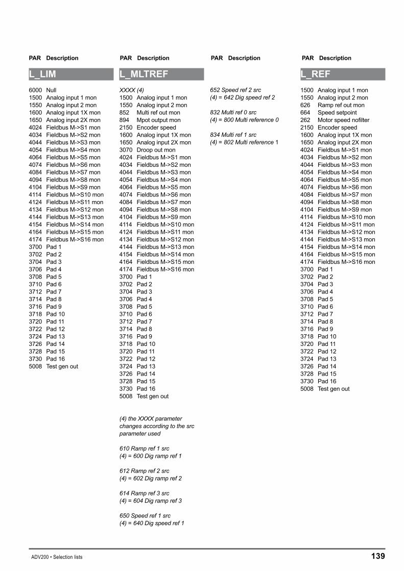
ADV200 • Selection lists 1�9
PAR Description PAR Description PAR Description PAR Description
L_LIM6000 Null1500 Analog input 1 mon1550 Analog input 2 mon1600 Analog input 1X mon1650 Analog input 2X mon4024 Fieldbus M->S1 mon4034 Fieldbus M->S2 mon4044 Fieldbus M->S3 mon4054 Fieldbus M->S4 mon4064 Fieldbus M->S5 mon4074 Fieldbus M->S6 mon4084 Fieldbus M->S7 mon4094 Fieldbus M->S8 mon4104 Fieldbus M->S9 mon4114 Fieldbus M->S10 mon4124 Fieldbus M->S11 mon4134 Fieldbus M->S12 mon4144 Fieldbus M->S13 mon4154 Fieldbus M->S14 mon4164 Fieldbus M->S15 mon4174 Fieldbus M->S16 mon3700 Pad 13702 Pad 23704 Pad 33706 Pad 43708 Pad 53710 Pad 63712 Pad 73714 Pad 83716 Pad 93718 Pad 103720 Pad 113722 Pad 123724 Pad 133726 Pad 143728 Pad 153730 Pad 165008 Test gen out
L_MLTREFXXXX (4)1500 Analog input 1 mon1550 Analog input 2 mon852 Multi ref out mon894 Mpot output mon2150 Encoder speed1600 Analog input 1X mon1650 Analog input 2X mon3070 Droop out mon4024 Fieldbus M->S1 mon4034 Fieldbus M->S2 mon4044 Fieldbus M->S3 mon4054 Fieldbus M->S4 mon4064 Fieldbus M->S5 mon4074 Fieldbus M->S6 mon4084 Fieldbus M->S7 mon4094 Fieldbus M->S8 mon4104 Fieldbus M->S9 mon4114 Fieldbus M->S10 mon4124 Fieldbus M->S11 mon4134 Fieldbus M->S12 mon4144 Fieldbus M->S13 mon4154 Fieldbus M->S14 mon4164 Fieldbus M->S15 mon4174 Fieldbus M->S16 mon3700 Pad 13702 Pad 23704 Pad 33706 Pad 43708 Pad 53710 Pad 63712 Pad 73714 Pad 83716 Pad 93718 Pad 103720 Pad 113722 Pad 123724 Pad 133726 Pad 143728 Pad 153730 Pad 165008 Test gen out
(4) the XXXX parameter changes according to the src parameter used
610 Ramp ref 1 src (4) = 600 Dig ramp ref 1
612 Ramp ref 2 src (4) = 602 Dig ramp ref 2
614 Ramp ref 3 src (4) = 604 Dig ramp ref 3
650 Speed ref 1 src (4) = 640 Dig speed ref 1
652 Speed ref 2 src (4) = 642 Dig speed ref 2
832 Multi ref 0 src (4) = 800 Multi reference 0
834 Multi ref 1 src (4) = 802 Multi reference 1
L_REF1500 Analog input 1 mon1550 Analog input 2 mon626 Ramp ref out mon664 Speed setpoint262 Motor speed nofilter2150 Encoder speed1600 Analog input 1X mon1650 Analog input 2X mon4024 Fieldbus M->S1 mon4034 Fieldbus M->S2 mon4044 Fieldbus M->S3 mon4054 Fieldbus M->S4 mon4064 Fieldbus M->S5 mon4074 Fieldbus M->S6 mon4084 Fieldbus M->S7 mon4094 Fieldbus M->S8 mon4104 Fieldbus M->S9 mon4114 Fieldbus M->S10 mon4124 Fieldbus M->S11 mon4134 Fieldbus M->S12 mon4144 Fieldbus M->S13 mon4154 Fieldbus M->S14 mon4164 Fieldbus M->S15 mon4174 Fieldbus M->S16 mon3700 Pad 13702 Pad 23704 Pad 33706 Pad 43708 Pad 53710 Pad 63712 Pad 73714 Pad 83716 Pad 93718 Pad 103720 Pad 113722 Pad 123724 Pad 133726 Pad 143728 Pad 153730 Pad 165008 Test gen out

140 ADV200 • Selection lists
PAR Description PAR Description PAR Description PAR Description
L_SCOPE6000 Null
L_VREFXXXX (5)3104 Inertia comp mon3374 Vf catch out1500 Analog input 1 mon1550 Analog input 2 mon1600 Analog input 1X mon1650 Analog input 2X mon4024 Fieldbus M->S1 mon4034 Fieldbus M->S2 mon4044 Fieldbus M->S3 mon4054 Fieldbus M->S4 mon4064 Fieldbus M->S5 mon4074 Fieldbus M->S6 mon4084 Fieldbus M->S7 mon4094 Fieldbus M->S8 mon4104 Fieldbus M->S9 mon4114 Fieldbus M->S10 mon4124 Fieldbus M->S11 mon4134 Fieldbus M->S12 mon4144 Fieldbus M->S13 mon4154 Fieldbus M->S14 mon4164 Fieldbus M->S15 mon4174 Fieldbus M->S16 mon3700 Pad 13702 Pad 23704 Pad 33706 Pad 43708 Pad 53710 Pad 63712 Pad 73714 Pad 83716 Pad 93718 Pad 103720 Pad 113722 Pad 123724 Pad 133726 Pad 143728 Pad 153730 Pad 166000 Null5008 Test gen out
(5) the XXXX parameter changes according to the src parameter used
2382 Torque ref 1 src (5) = 2380 Dig torque ref 1
2492 Vf scale src (5) = 2490 Dig Vf scale
3002 Speed ratio src (5) = 3000 Dig speed ratio
L_WDECOMPXXXX (6)6000 Null6002 One4432 Word comp mon4024 Fieldbus M->S1 mon4034 Fieldbus M->S2 mon4044 Fieldbus M->S3 mon4054 Fieldbus M->S4 mon4064 Fieldbus M->S5 mon4074 Fieldbus M->S6 mon4084 Fieldbus M->S7 mon4094 Fieldbus M->S8 mon4104 Fieldbus M->S9 mon4114 Fieldbus M->S10 mon4124 Fieldbus M->S11 mon4134 Fieldbus M->S12 mon4144 Fieldbus M->S13 mon4154 Fieldbus M->S14 mon4164 Fieldbus M->S15 mon4174 Fieldbus M->S16 mon3700 Pad 13702 Pad 23704 Pad 33706 Pad 43708 Pad 53710 Pad 63712 Pad 73714 Pad 83716 Pad 93718 Pad 103720 Pad 113722 Pad 123724 Pad 133726 Pad 143728 Pad 153730 Pad 16
(6) the XXXX parameter changes according to the src parameter use
4452 Word decomp src (6) = 4450 Dig word decomp

ADV200 • Troubleshooting 141
D–TROUBLESHOOTING
Note ! To reset alarms, see Quick start guide, paragraph6.6.1. In the following table, the Code is visible only from serial line.
Code Errormessageshownonthedisplay
Sub-code Description
0 Noalarm Condition:No alarm present
1 OvervoltageCondition:DClinkovervoltagealarmduetoenergyrecoveredfromthemotor.The voltage arriving at the drive power section is too high compared to the maximum threshold relating to the PAR 560 Mainsvoltageparameter setting.Solution:- Extend the deceleration ramp.- Use a braking resistor between terminals BR1 and BR2 to dissipate the recovered energy
2 Undervoltage
Condition:DC link undervoltage alarm. The voltage arriving at the drive power section is too low compared to the minimum threshold relating to the 560 Mains voltage parameter setting due to:.- the mains voltage being too low or overextended voltage drops.- poor cable connections (e.g. loose contactor terminals, inductance, filter, etc. ). Solution:Check the connections.
3 Groundfault Condition:Ground short circuit alarmSolution:- Check drive and motor wiring.- Check that the motor is not grounded.
4 OvercurrentCondition:Instantaneousovercurrentprotectioninterventionalarm.This may be due to the incorrect setting of current regulator parameters or a short circuit between phases or ground fault on the drive output.Solution:- Check the current regulator parameters- Check wiring towards the motor
5 Desaturation Condition:InstantaneousovercurrentintheIGBTbridgealarm.Solution:Switch the drive off and then switch it on again. If the alarm persists, contact the technical service centre.
6 MultiUndervolt Condition:The number of attempted automatic restarts after the Undervoltage alarm has exceeded the set Undervresattempt value in the Undervresdelaytime.Solution:Too many Undervoltage alarms. Adopt the proposed solutions for the Undervoltage alarm.
7 MultiOvercurr Condition:2 attempted automatic restarts after the Overcurrent alarm within 30 seconds. If more than 30 seconds pass after the Overcurrent alarm was generated, the attempt counter is reset.Solution:Too many Overcurrent alarms. Adopt the proposed solutions for the Overcurrent alarm.
8 MultiDesat Condition:2 attempted at automatic restarts after the Desaturation alarm within 30 seconds. If more than 30 seconds pass after the Desaturation alarm was generated, the attempt counter is reset.Solution: Too many Desaturation alarms. Adopt the proposed solutions for the Desaturationalarm.
9 HeatsinkOT Condition:Heatsink temperature too high alarmSolution:- Verify the correct operation of the cooling fan.- Check that the heatsinks are not clogged
10 HeatsinkSOTUTCondition:Heatsink temperature too high or too low alarm The temperature has exceeded the upper or lower limit set for the linear temperature transducer.Solution: Solution:- Verify the correct operation of the cooling fan.- Check that the heatsinks are not clogged- Check that the openings for the cabinet cooling air are not blocked.
11 IntakeairOT Condition:Intake air temperature too high alarm.Solution:Check correct fan operation

14� ADV200 • Troubleshooting
Code Errormessageshownonthedisplay
Sub-code Description
12 MotorOT
Condition:Motor overtemperature alarm. Possible causes:- Load cycle too heavy- The motor is installed in a place where the ambient temperature is too high- If the motor is provided with a blower: the fan is not working- If the motor is not provided with a blower: the load is too high at slow speeds. Cooling the fan on the motor shaft is not sufficient for this load cycle.- The motor is used at less than the rated frequency, causing additional magnetic losses.Solution:- Change the processing cycle.- Use a cooling fan to cool the motor.
13 Driveoverload Condition:Drive overload alarm. The overload threshold of the accumulator of the I²t drive thermal image has been exceeded.Solution:Check that the size of the drive is suitable for the application.
14 MotoroverloadCondition:Motor overload alarm. The current absorbed during operation is greater than that specified on the motor data plate. The overload threshold of the accumulator of the I²t motor thermal image has been exceeded.Solution:- Reduce the motor load.- Increase the size of the motor.
15 BresoverloadCondition:Braking resistor overload alarm. The current absorbed by the resistor is greater than the rated current. The overload threshold of the accumulator of the I²t braking resistor thermal image has been exceeded.Solution:Increase the Watt value of the braking resistor
16 Phaseloss Condition:Power phase loss alarm.Solution:Check the mains voltage and whether any protections upstream of the drive have been tripped.
17 OptBusfault Condition:Error in the configuration stage or communication error.XXXXH-X The XXXXH-X code indicates the reason for the error: make a note of this to discuss it with the
service centre.XXXXH-X The XXXXH-X code indicates the reason for the error: make a note of this to discuss it with the
service centre.XXXXH-X The XXXXH-X code indicates the reason for the error: make a note of this to discuss it with the
service centre.Solution:For configuration errors, check the configuration of the Bus communication, Bus type, Baudrate, address.For communication errors verify wiring, resistance of terminations, interference immunity, timeout settings.
18 Opt1IOfault Condition:Error in the communication between Regulation and I/O expansion card in slot 1Solution:Check that it has been inserted correctly, see chapter 11.5.
19 Opt2IOfault Condition:Error in the communication between Regulation and I/O expansion card in slot 2 or 3Solution:Check that it has been inserted correctly , see chapter 11.5.
20 OptEncfault Condition:Error in the communication between Regulation and Encoder feedback card.Solution:Check that it has been inserted correctly , see chapter 11.5.
21 Externalfault Condition:External alarm present. A digital input has been programmed as an external alarm, but the +24V voltage is not available on the terminal.Solution:Check that the terminal screws are tight

ADV200 • Troubleshooting 14�
Code Errormessageshownonthedisplay
Sub-code Description
22 SpeedfbklossCondition:Speed feedback loss alarm. The encoder is not connected, not connected properly or not powered: verify encoder operation by selecting the Motorspeed parameter in the MONITOR menu.Solution:- Check encoder wiring for integrity.- Check that the encoder is connected to the power supply.- With the drive disabled, turn the motor clockwise (seen from the motor shaft side). A positive value must be displayed.- If the value does not change or values are indicated randomly, check the encoder power supply and cables.- If the value displayed is negative, invert the encoder connections. Change channel A+ and A- or B+ and B-.- Check that the encoder electronics are consistent with those of the relative expansion card.
23 Overspeed Condition:Motor overspeed alarm. The motor speed exceeds the limits set in the Speedreftoplimand Speedrefbottomlimparameters.Solution:- Limit the speed reference.- Check that the motor is not driven in overspeed during rotation.
24 Speedrefloss Condition:Allarme perdita del riferimento di velocità. Causa probabile interruzione dei cavi del riferimento analogico o serraggio allentato dei relativi morsettiSolution:- Controllare il cablaggio del riferimento di velocità- Serrare le viti dei morsetti dell’ingresso analogico
25 EmgstopalarmCondition:Emergency stop alarm. The Stop key on the keypad was pressed with the Stopkeymodeparam-eter set to EmgStop&Alarmin case of Remote->Terminal Strip or Remote->Digital or Local->Terminal Strip mode.Solution:Eliminate the reason for which the Stop key on the keypad was pressed and reset the drive.
26 Powerdown Condition:The drive was enabled with no supply voltage at the power section.Solution:Emergency stop alarm. The Stop key on the keypad was pressed with the Stopkeymodeparameter set to EmgStop&Alarmin case of Remote->Terminal Strip or Remote->Digital or Local->Terminal Strip mode.
27...32NotUsed1
...NotUsed6
33...40Plc1fault
...Plc8fault
Condition:Enabled application developed in the IEC 61131-3 environment has found the conditions for generating this specific alarm to be true. The meaning of the alarm depends on the type of application. For more information, refer to the documentation concerning the specific application..
XXXXH-X The XXXXH-X code indicates the reason for the error: make a note of this to discuss it with the service centre.
Solution:Refer to the documentation concerning the enabled application.
41 Watchdog
Condition:this condition can occur during operation when the watchdog micro protection is enabled; the alarm is included in the list of alarms and alarm log. After this alarm:- the drive automatically runs a reset- motor control is not available.
XXXXH-X The XXXXH-X code indicates the reason for the error: make a note of this to discuss it with the service centre.
Solution:If the alarm was a consequence of a variation to the drive configuration (parameter setting, installation of an option, downloading of a PLC application), remove it.Switch the drive off and then switch it on again.

144 ADV200 • Troubleshooting
Code Errormessageshownonthedisplay
Sub-code Description
42 Traperror
Condition:this condition can occur during operation when the trap micro protection is enabled; the alarm is included in the list of alarms and alarm log. After this alarm:- the drive automatically runs a reset- motor control is not available.
XXXXH-X The XXXXH-X (SubHandler-Class) code indicates the reason for the error: make a note of this to discuss it with the service centre.
Solution: If the alarm was a consequence of a variation to the drive configuration (parameter setting, installa-tion of an option, downloading of a PLC application), remove it.Switch the drive off and then switch it on again.
43 Systemerror
Condition: this condition can occur during operation when the operating system protection is enabled; the alarm is included in the list of alarms and alarm log. After this alarm:- the drive automatically runs a reset- motor control is not available.
XXXXH-X The XXXXH-X (Error-Pid) code indicates the reason for the error: make a note of this to discuss it with the service centre.
Solution:If the alarm was a consequence of a variation to the drive configuration (parameter setting, installa-tion of an option, downloading of a PLC application), remove it.Switch the drive off and then switch it on again.
44 Usererror
Condition:this condition can occur during operation when the software protection is enabled; the alarm is included in the list of alarms and alarm log. After this alarm:- the drive automatically runs a reset- motor control is not available.
XXXXH-X The XXXXH-X (Error-Pid) code indicates the reason for the error: make a note of this to discuss it with the service centre.
Solution:If the alarm was a consequence of a variation to the drive configuration (parameter setting, installation of an option, downloading of a PLC application), remove it.Switch the drive off and then switch it on again.
45 Paramerror Condition:if an error occurs during the enabling of the parameter database saved in the Flash memory; the alarm is included in the list of alarms and alarm log.
XXXXH-X The XXXXH-X code indicates the reason for the error: make a note of this to discuss it with the service centre.
Solution:Set the parameter causing the error to the correct value and run Saveparameter. Switch the drive off and then switch it back on again.
46 Loaddefault
Condition:this can occur during loading of the parameter database saved in the Flash memoryit is normal if it appears in the following conditions: the first time the drive is switched on, when a new version of the firmware is downloaded, when the regulation is installed on a new size, when a new region is entered. If this message appears when the drive is already in use it means there has been a problem in the parameter database saved in the Flash memory.If this message appears the drive automatically runs the Load default command.
0001H-1 The database saved is not valid0002H-2 The database saved is not compatible0003H-3 The saved database refers to a different size and not to the current size0004H-4 The saved database refers to a different region and not to the current region
Solution:Set the parameters to the desired value and run Save parameter

ADV200 • Troubleshooting 145
Code Errormessageshownonthedisplay
Sub-code Description
47 Plccfgerror Condition: this can occur during loading of the MDPLC applicationThe Mdplc application present on the drive is not run.
0004H-4 The application that has been downloaded has a different Crc on the DataBlock and Function table.
0065H-101 The application that has been downloaded has an invalid identification code (Info).0066H-102 The applciation that has been downloaded uses an incorrect task number (Info).0067H-103 The application that has been downloaded has an incorrect software configuration.
0068H-104 The application that has been downloaded has a different Crc on the DataBlock and Function table.
0069H-105
A Trap error or System error has occurred.The drive has automatically executed a Power-up operation.Application not executed.See the Alarm List for more information about an error that has occurred.
006AH-106 The application that has been downloaded has an invalid identification code (Task).006BH-107 The application that has been downloaded uses an incorrect task number (Task).006CH-108 The application that has been downloaded has an incorrect Crc (Tables + Code)
Solution:Remove the MDPLC application or download a correct MDPLC application.
48 Loadpardefplc
Condition:this can occur during loading of the parameter database saved in the Flash memory of the MDPLC application it is normal if it appears the first time the drive is switched on, after downloading a new application. If this mes-sage appears when the drive is already in use it means there has been a problem in the parameter database saved in the Flash memory.If this message appears the drive automatically runs the Load default command.
0001H-1 The database saved is not validSolution:Set the parameters to the desired value and run Save parameter.
49 Keyfailed Condition:Shis may occur at drive power-on if the incorrect enabling key was inserted for a given firmware function.
0001H-1 Incorrect PLC key. PLC application not available.Solution:Ask Gefran for the correct key to enable the desired firmware function.

146 ADV200 • Messages
E–MESSAGES
Note ! For more information see Quick start guide, chapter6.7.
Errormessageshownonthedisplay
Sub-code Description
Autotune Condition:this may occur during the self-tuning procedure0 No error
1 The commands are not configured in Local mode.Solution: Execute the requested configuration
2 The Commands local sel parameter has not been configured from the keypadSolution: Execute the requested configuration
3The motor plate data parameters have changed but the Takeparameterscommand, PAR 2020, has not been executedSolution: Execute the Takeparameters command.
4 The motor is not connectedSolution: Connect the motor
5
While running self-tuning the ESC key was pressed or the enable contact was opened or an alarm occurred. The self-tuning command was sent with the drive in the alarm conditionSolution: Eliminate the reason for the alarm, remove the reason for the opening of the enable contact, reset alarms.
6A setting performed by the self-tuning function produced a parameter value outside the min or max range.Solution: Check the motor plate data or drive and motor sizes have been combined incorrectly.
7 The self-tuning command was sent without being enabled.Solution: Close the enable contact before sending the self-tuning command
8...21 A setting performed by self-tuning has reached a measurement method limitSolution: Check the motor plate data or the drive and motor sizes have been combined incorrectly.
Solution: If the message appears with a value other than 0, follow the instructions supplied for each particular case and repeat self-tuning. This should be performed using the wizard function available from the keypad (STARTUP WIZARD) and the Tool software on the PC.Pay attention to all motor plate data parmaeters, especially:- Ratedspeed, Motorratedspeedin rpm. - Ratedfrequency, Motorratedfrequencyin Hz- Polepairs, MotorpolepairsTake care not to set the Ratedspeedparameter to the synchronous speed. The value of the Ratedspeedparameter must be less than: [(Ratedfrequency * 60) / Polepairs].If the problem persists even after following the instructions supplied, confirm the values of the motor plate data parameters, execute the Takeparameters command but not self-tuning.
Keyexpiring Condition:this may occur at drive power-on if the incorrect enabling key was inserted for a given firmware function. At this stage the firmware function can still be used freely, but this time limit is about to expire.
xxxxH-x Number of hours for which the function can still be used freely.Solution: Ask Gefran for the correct key to enable the desired firmware function.
Loaddefault
Condition:may occur during loading of the parameter database saved in flashnormally appears in the following conditions: at initial power-on when a new firmware version is downloaded, when the regulation is installed on a new size, when the region is changed.If this message is displayed when the drive is already operating, this means that a problem has occurred in the parameter database saved in Flash.If this message is displayed, the drive automatically performs the Load default command.
0001H-1 The database saved is not valid0002H-2 The database saved is not compatible0003H-3 The database saved refers to a different size from the current size0004H-4 The database saved refers to a different region from the current region
Solution:Set the parameters to the value required and perform Saveparameter
Loaddefplc
Condition:may occur during loading of the parameter database saved in the Flash of the Mdplc applicationNormally appears at initial power-on after downloading a new application.If this message is displayed when the drive is already operating, this means that a problem has occurred in the parameter database saved in Flash.If this message appears the drive restores the default database, i.e. the one that was downloaded.
0001H-1 The database saved is not validSolution:Set the parameters to the value required and perform Saveparameter
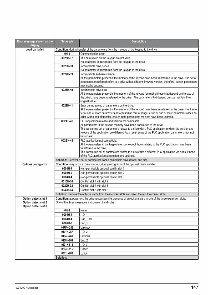
ADV200 • Messages 147
Errormessageshownonthedisplay
Sub-code Description
Loadparfailed Condition:during transfer of the parameters from the memory of the keypad to the drive0H-0 Communication error
0025H-37 The data saved on the keypad are not valid. No parameter is transferred from the keypad to the drive
0026H-38 Incompatible drive series.No parameter is transferred from the keypad to the drive
0027H-39 Incompatible software version.All the parameters present in the memory of the keypad have been transferred to the drive. The set of parameters transferred refers to a drive with a different firmware version; therefore, certain parameters may not be updated.
0028H-40 Incompatible drive size.All the parameters present in the memory of the keypad (excluding those that depend on the size of the drive), have been transferred to the drive. The parameters that depend on size maintain their original value.
0029H-41 Error during saving of parameters on the drive.All the parameters present in the memory of the keypad have been transferred to the drive. The trans-fer of one or more parameters has caused an “out of range” error, or one or more parameters does not exist. At the end of transfer, one or more parameters may not have been updated.
002AH-42 PLC application release and version not compatible.All parameters in the keypad memory have been transferred to the drive.The transferred set of parameters relates to a drive with a PLC application in which the version and release of the application are different. As a result some of the PLC application parameters may not be updated.
002BH-43 PLC application not compatible.All the parameters in the keypad memory except those relating to the PLC applciation have been transferred to the drive.The transferred set of parameters relates to a drive with a different PLC application. As a result none of the PLC application parameters are updated.
Solution:Recover a set of parameters from a compatible drive (model and size)Optionsconfigerror Condition:may occur at drive start-up, during recognition of the optional cards installed
0001H-1 Non-permissible optional card in slot 10002H-2 Non-permissible optional card in slot 20004H-4 Non-permissible optional card in slot 3
0010H-16 Conflict slot 1 with slot 20020H-32 Conflict slot 1 with slot 30040H-64 Conflict slot 2 with slot 3
Solution:Remove the optional cards from the incorrect slots and insert them in the correct slotsOptiondetectslot1Optiondetectslot2Optiondetectslot3
Condition: at power-on, the drive recognizes the presence of an optional card in one of the three expansion slots.One of the three messages is shown on the display
0H-0 None0001H-1 I_O_10004H-4 Can_Dnet0008H-8 Enc_1
00FFH-255 Unknown0101H-257 I_O_20104H-260 Profibus0108H-264 Enc_20201H-513 I_O_30204H-516 Gdnet0301H-769 I_O_4
Solution:
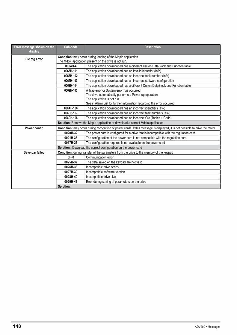
14� ADV200 • Messages
Errormessageshownonthedisplay
Sub-code Description
Plccfgerror Condition:may occur during loading of the Mdplc applicationThe Mdplc application present on the drive is not run.
0004H-4 The application downloaded has a different Crc on DataBlock and Function table0065H-101 The application downloaded has an invalid identifier (Info)0066H-102 The application downloaded has an incorrect task number (Info)0067H-103 The application downloaded has an incorrect software configuration0068H-104 The application downloaded has a different Crc on DataBlock and Function table0069H-105 A Trap error or System error has occurred.
The drive automatically performs a Power-up operation.The application is not run. See in Alarm List for further information regarding the error occurred
006AH-106 The application downloaded has an incorrect identifier (Task)006BH-107 The application downloaded has an incorrect task number (Task)006CH-108 The application downloaded has an incorrect Crc (Tables + Code)
Solution:Remove the Mdplc application or download a correct Mdplc applicationPowerconfig Condition:may occur during recognition of power cards. If this message is displayed, it is not possible to drive the motor.
0020H-32 The power card is configured for a drive that is incompatible with the regulation card0021H-33 The configuration of the power card is not compatible with the regulation card0017H-23 The configuration required is not available on the power card
Solution:Download the correct configuration on the power cardSaveparfailed Condition:during transfer of the parameters from the drive to the memory of the keypad
0H-0 Communication error0025H-37 The data saved on the keypad are not valid0026H-38 Incompatible drive series0027H-39 Incompatible software version0028H-40 Incompatible drive size0029H-41 Error during saving of parameters on the drive
Solution:
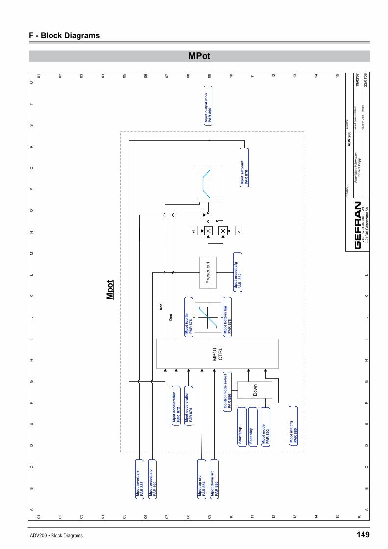
ADV200 • Block Diagrams 149
F-BlockDiagrams
MPot
ADV200
19/02/07
Mpo
t
MPO
TCTR
L
Mpotinvertsrc
PAR888
Mpotp
resetsrc
PAR890
Mpoto
utputm
on890
PAR
Mpotinitcfg
880
PAR
Mpotp
resetcfg
P882
AR
Mpotm
ode
892
PAR
Filena
me:
Issued
Date---
Initials:
RevisionDate--Initials:
01 02 03 04 05 06 07 08 09 10 11 12 13 14 15 16Pr
oprie
tary
Info
rmat
ion
DoNot
Copy
PRODUCT:
01 02 03 04 05 06 07 08 09 10 11 12 13 14 15
AB
CD
EF
GH
IJ
KL
MN
OP
QR
ST
U
AB
CD
EF
GH
IJ
KL
Via
Car
ducc
i,24
I-21040
Gerenzano
VA
Mpotb
ottomlim
878
PAR
Mpottop
lim876
PAR
Mpotacceleration
P872
AR
Mpotd
eceleration
874
PAR
Dow
nFaststop
Start/stop
Preset
ctrl
+1 -1
Acc
Dec
Controlmodeselect
556
PAR
Mpotu
psrc
884
PAR
Mpotd
ownsrc
886
PAR
Mpotsetpoint
870
PAR
22/01/08
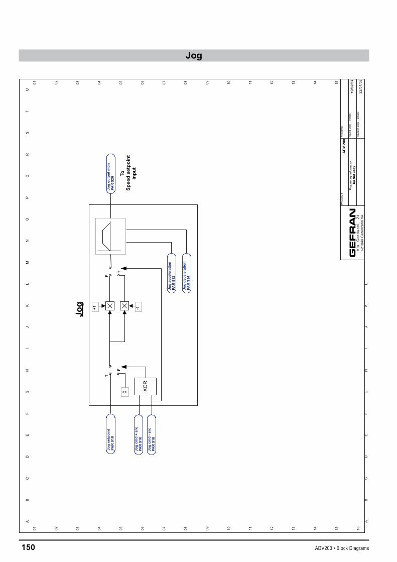
150 ADV200 • Block Diagrams
01 02 03 04 05 06 07 08 09 10 11 12 13 14 15 16
01 02 03 04 05 06 07 08 09 10 11 12 13 14 15
AB
CD
EF
GH
IJ
KL
MN
OP
QR
ST
U
AB
CD
EF
GH
IJ
KL
ADV200
19/02/07
Filena
me:
Issued
Date---
Initials:
RevisionDate--Initials:
Prop
rieta
ryIn
form
atio
nDoNot
Copy
PRODUCT:
Via
Car
ducc
i,24
I-210
40Geren
zano
VA22
/01/08
Jog
Jogsetpoint
PAR910
Jogcm
d+src
PAR916
+1 -1
Jogacceleration
PAR912
Jogdeceleration
PAR914
Jogoutputmon
PAR920
Jogcm
d-src
PAR916
0
F
TF
T
ToSp
eedsetpoint
input
XOR
Jog

ADV200 • Block Diagrams 151
RampRef-Referenceskip
T
F
T
F
F
T
Ram
pRef
Ram
pref1
src
610
PAR
Ram
pref2
src
612
PAR
+ +
+1 -1
Digrampref1
600
PAR
Digrampref2
602
PAR
Reference
Skip
Reference
skipset
630
PAR
Reference
skipband
632
PAR
Reference
in
Reference
out
Ram
psetpoint
628
PAR
Ram
pref1
mon
620
PAR
Ram
pref3
mon
624
PAR
Ram
prefinvertsrc
616
PAR
01 02 03 04 05 06 07 08 09 10 11 12 13 14 15 16
01 02 03 04 05 06 07 08 09 10 11 12 13 14 15
AB
CD
EF
GH
IJ
KL
MN
OP
QR
ST
U
AB
CD
EF
GH
IJ
KL
Ram
prefo
utmon
626
PAR
FastStop 0
Start/S
top
0Analoginput1
mon
1500
PAR
Multirefo
utmon
PAR852
Ram
pref3
src
PAR614
Digrampref3
PAR604
Analoginput1Xmon
1600
PAR
Multirefo
utmon
PAR852
Local/rem
otemon
1030
PAR
Ram
pref2
mon
622
PAR
Local
Rem
ote
ADV200
19/02/07
Filename:
Issued
Date---
Initials:
RevisionDate--Initials:
Prop
rieta
ryIn
form
atio
nDoNot
Copy
PRODUCT:
Via
Car
ducc
i,24
I-210
40Gerenzano
VA22/01/08

15� ADV200 • Block Diagrams
Ramp
0
Line
ar
Shap
e
0
ToSp
eed
setp
oint
inpu
t
F
T
Byp
ass
Ram
pfu
nctio
n
CTR
L
0off
F
T
Ram
p
Mul
tiR
amp
Ram
pse
tpoi
nt62
8PA
R
Ram
pin
zero
src
750
PAR
Ram
pou
tzer
osr
c75
2PA
R
Ram
pou
tzer
osr
cPA
R75
2
Ram
pfr
eeze
src
754
PAR
Acc
eler
atio
ntim
e0
700
PAR
Dec
eler
atio
ntim
e0
702
PAR
Acc
elje
rktim
e0
730
PAR
Dec
elje
rktim
e0
PAR
732
Acc
eler
atio
ntim
e3
712
PAR
Dec
eler
atio
ntim
e3
714
PAR
Acc
elje
rktim
e3
742
PAR
Dec
elje
rktim
e3
744
PAR
Acc
eler
atio
ntim
e2
708
PAR
Dec
eler
atio
ntim
e2
710
PAR
Acc
elje
rktim
e2
738
PAR
Dec
elje
rktim
e2
740
PAR
Mul
tira
mp
sel0
src
722
PAR
Mul
tira
mp
sel1
src
724
PAR
Mul
tira
mp
selm
onIP
A72
6
01 02 03 04 05 06 07 08 09 10 11 12 13 14 15 16
01 02 03 04 05 06 07 08 09 10 11 12 13 14 15
AB
CD
EF
GH
IJ
KL
MN
OP
QR
ST
U
AB
CD
EF
GH
IJ
KL
Ram
pty
pe72
0PA
R
Mltrampsel
Acc
eler
atio
ntim
e1
704
PAR
Dec
eler
atio
ntim
e1
706
PAR
Acc
elje
rktim
e1
734
PAR
Dec
elje
rktim
e1
PAR
736
AD
V20
0
19/0
2/07
Filena
me:
Issued
Date---
Initials:
RevisionDate--Initials:
Prop
rieta
ryIn
form
atio
nD
oN
otC
opy
PRODUCT:
Via
Car
ducc
i,24
I-210
40Geren
zano
VA22
/01/08
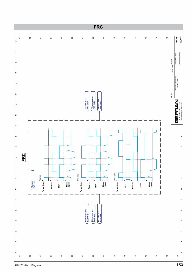
ADV200 • Block Diagrams 15�
FRC
Normal
Twowire
Threewire
Forwardstart
Forwardstart
Reverse
Start
Start
StopMotor
Speed
Motor
Speed
Motor
Speed
Reverse
Reverse
Forwardstart
Start
01 02 03 04 05 06 07 08 09 10 11 12 13 14 15 16
01 02 03 04 05 06 07 08 09 10 11 12 13 14 15
AB
CD
EF
GH
IJ
KL
MN
OP
QR
ST
U
AB
CD
EF
GH
IJ
KL
FRC
FRforwardsrc
1042
PAR
FRreversesrc
1044
PAR
FR*stopsrc
1046
PAR
FRmode
1040
PAR
FRstartm
onPAR1048
FRreversemon
PAR1050
FRcm
dmon
PAR1052
ADV200
19/02/07
Filena
me:
Issued
Date---
Initials:
RevisionDate--Initials:
Prop
rieta
ryIn
form
atio
nDoNotCopy
PRODUCT:
Via
Car
ducc
i,24
I-210
40Geren
zano
VA22
/01/08

154 ADV200 • Block Diagrams
MultiReferenceMultiReference
Multiref0src
PAR832
Multiref1src
PAR834
Multireference2
PAR804
Multireference3
PAR806
Multireference4
PAR808
Multireference5
PAR810
Multireference6
PAR812
Multireference7
PAR814
Multireference8
PAR816
Multireference9
PAR818
Multireference10
PAR820
Multireference11
PAR822
Multireference12
PAR824
Multireference13
PAR826
Multireference14
PAR828
Multireference15
PAR830
Multirefoutmon
PAR852
Multirefsel0
PAR840
Multirefsel1
PAR842
Multirefsel2
PAR844
Multirefsel3
PAR846
Mltrefselector
Multirefselmon
PAR850
Multireference0
PAR800
Multireference1
PAR802
01 02 03 04 05 06 07 08 09 10 11 12 13 14 15 16
01 02 03 04 05 06 07 08 09 10 11 12 13 14 15
AB
CD
EF
GH
IJ
KL
MN
OP
QR
ST
U
AB
CD
EF
GH
IJ
KL
ADV200
19/02/07
Filena
me:
Issued
Date---
Initials:
RevisionDate--Initials:
Prop
rieta
ryIn
form
atio
nDoNotCopy
PRODUCT:
Via
Car
ducc
i,24
I-210
40Geren
zano
VA22
/01/08

ADV200 • Block Diagrams 155
SpeedReference
T
+ +
+ +
+1 -1
F
T0
F
0
FFrom
Ram
pou
tput
From
Jogou
tput
Spee
dReferen
ce
Spee
dref1
mon
PAR66
0
Spee
dref2
mon
PAR66
2
Spee
drefb
ottom
limPA
R67
2
Spee
dreftop
limPA
R67
0
Spee
dse
tpoint
PAR66
4
Spee
dratio
mon
PAR30
04
Start/S
top
01 02 03 04 05 06 07 08 09 10 11 12 13 14 15 16
01 02 03 04 05 06 07 08 09 10 11 12 13 14 15
AB
CD
EF
GH
IJ
KL
MN
OP
QR
ST
U
AB
CD
EF
GH
IJ
KL
Spee
dref1
src
PAR65
0
Dig
spee
dratio
PAR30
00
Dig
spee
dref1
PAR64
0
Dig
speedref2
PAR642
Spee
dratio
src
PAR30
02
Spee
drefinv
erts
rcPA
R65
4
Con
trol
mod
ese
lect
PAR55
6
Fast
Stop
Spee
dref2
src
PAR65
2
ADV20
0
19/02/07
Filena
me:
Issued
Date---
Initials:
RevisionDate--Initials:
Prop
rieta
ryIn
form
atio
nDoNot
Cop
y
PRODUCT:
Via
Car
ducc
i,24
I-210
40Geren
zano
VA22
/01/08
Spee
dratio
out
PAR30
04

156 ADV200 • Block Diagrams
SpeedZero
Speed/ReferenceSpeed/Reference
iszeroSpeed/Reference
iszerodelay
Zero
dela
y
Zero
thr
Sp
ee
dZ
ero
Sp
ee
d0
thr
PA
R940
Sp
ee
d0
dela
y
PA
R942
Refe
ren
ce
0th
r
PA
R930
Refe
ren
ce
0d
ella
yP
AR
932
Sp
eed
iszero
dela
y
PA
R946
Sp
eed
iszero
PA
R944
Ref
iszero
dela
y
PA
R936
Ref
iszero
PA
R934
01 02 03 04 05 06 07 08 09 10 11 12 13 14 15 16
01 02 03 04 05 06 07 08 09 10 11 12 13 14 15
AB
CD
EF
GH
IJ
KL
MN
OP
QR
ST
U
AB
CD
EF
GH
IJ
KL
AD
V200
19/0
2/0
7
Filename:
Issued
Date---
Initials:
RevisionDate--Initials:
Prop
rieta
ryIn
form
atio
nD
oN
ot
Co
py
PRODUCT:
Via
Car
ducc
i,24
I-210
40Geren
zano
VA
On
“L
_D
IGS
EL
1”
an
d“L
_D
IGS
EL
3”
sele
cti
on
lists
22/01/08

ADV200 • Block Diagrams 157
GainAdapt
Ref
Ref
Gainad
apt
Spee
dregP1
gain
PAR20
02
Spee
dregI2
time
PAR22
06
Spee
dregI1
time
PAR22
02
Spee
dregP2
gain
PAR22
04
Gainad
apts
pdba
nd12
PAR22
20
Gainad
apts
pdthr1
2PA
R22
18
Gainad
apts
rcPA
R22
16
SpdregItim
eInus
ePA
R22
34
SpdregPga
inInus
ePA
R22
32
Spee
dregP0
gain
PAR22
28
Spee
dregI0
time
PAR22
30
Gain0en
able
PAR22
26
01 02 03 04 05 06 07 08 09 10 11 12 13 14 15 16
01 02 03 04 05 06 07 08 09 10 11 12 13 14 15
AB
CD
EF
GH
IJ
KL
MN
OP
QR
ST
U
AB
CD
EF
GH
IJ
KL
ADV20
0
19/02/07
Filena
me:
Issued
Date---
Initials:
RevisionDate--Initials:
Prop
rieta
ryIn
form
atio
nDoNot
Cop
y
PRODUCT:
Via
Car
ducc
i,24
I-210
40Geren
zano
VA22
/01/08
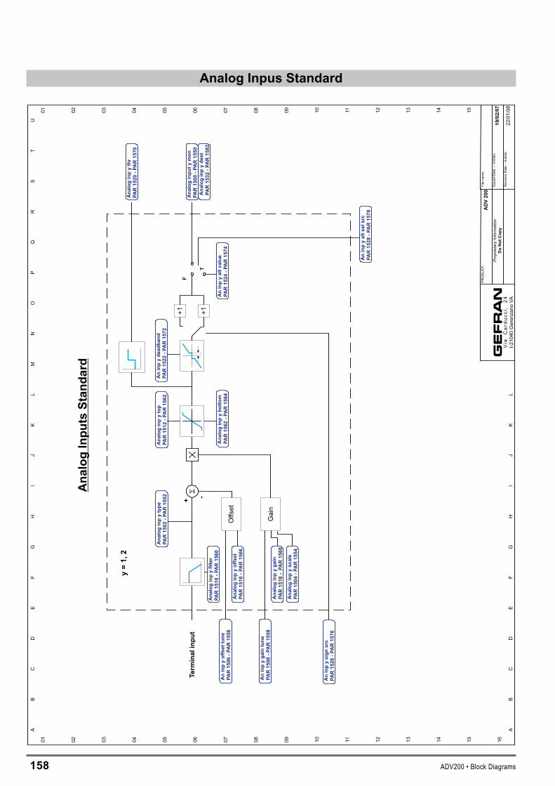
15� ADV200 • Block Diagrams
AnalogInpusStandard
Term
inalinput
+ -+1+1
F
T
y=1,2
Offset
Gain
AnalogInputsStandard
Analoginpytype
PAR1502
-PAR1552
Aninpyoffsettune
PAR1506
-PAR1556
Analoginpyoffset
PAR1516
-PAR1566
Aninpygaintune
PAR1508
-PAR1558
Analoginpygain
PAR1518
-PA
R1568
Analoginpyscale
PAR1504
-PAR1554
Analoginpybo
ttom
PAR1562
-PAR1564
Analoginpytop
PAR1512
-PAR1562
Aninpyaltvalue
PAR1524
-PAR1574
Aninpyaltselsrc
PAR1528
-PAR1578
Analoginpythr
PAR1520
-PAR1570
Analoginpu
tymon
PAR1500
-PAR1550
Analoginpydest
PAR1532
-PAR1582
01 02 03 04 05 06 07 08 09 10 11 12 13 14 15 16
01 02 03 04 05 06 07 08 09 10 11 12 13 14 15
AB
CD
EF
GH
IJ
KL
MN
OP
QR
ST
U
AB
CD
EF
GH
IJ
KL
Analoginpyfilter
PAR1510
-PAR1560
Aninpydeadband
PAR1522
-PAR1572
Aninpysign
src
PAR1526
-PAR1576
ADV200
19/02/07
Filename:
Issued
Date---
Initials:
RevisionDate--Initials:
Prop
rieta
ryIn
form
atio
nDoNot
Copy
PRODUCT:
Via
Car
ducc
i,24
I-210
40Geren
zano
VA22
/01/08

ADV200 • Block Diagrams 159
AnalogOutputs
-1
F
T
Y=2,
2X
-1
F
T
y=1,
1X
Ana
logOutpu
ts
Ana
logou
tysrc
PAR1802
-PAR...
Ana
logou
tyscale
PAR1810
-PAR...
Anou
tysign
src
PAR1826
-PAR...
Ana
logou
tymin
PAR1840
-PAR...
Ana
logou
tymax
PAR1842
-PAR...
Ana
logou
tytype
PAR1848
-PAR...
Ana
logou
tysrc
PAR1800
-PAR...
Ana
logou
tyscale
PAR1808
-PAR...
Anou
tysign
src
PAR1824
-PAR...
Ana
logou
tymin
PAR1832
-PAR...
Ana
logou
tymax
PAR1834
-PAR...
01 02 03 04 05 06 07 08 09 10 11 12 13 14 15 16
01 02 03 04 05 06 07 08 09 10 11 12 13 14 15
AB
CD
EF
GH
IJ
KL
MN
OP
QR
ST
U
AB
CD
EF
GH
IJ
KL
Ana
logou
tymon
PAR1816
-PAR...
Ana
logou
tymon
PAR1818
-PAR...
Term
inal
Outpu
tsStd/Ex
p
Term
inal
Outpu
tsStd/Ex
p
ADV200
19/02/07
Filename:
Issued
Date---
Initials:
RevisionDate--Initials:
Prop
rieta
ryIn
form
atio
nDoNot
Cop
y
PRODUCT:
Via
Car
ducc
i,24
I-21040
Gerenzano
VA22/01/08
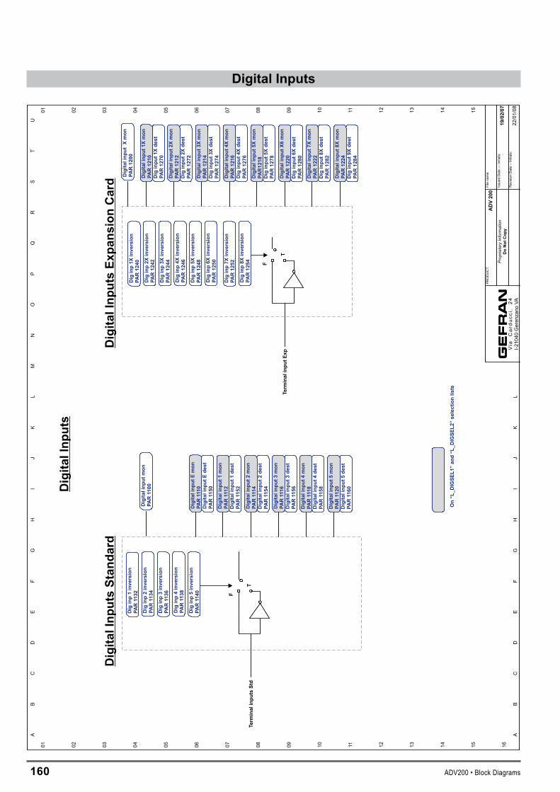
160 ADV200 • Block Diagrams
DigitalInputs
01 02 03 04 05 06 07 08 09 10 11 12 13 14 15
F
T
F
T
Term
inal
inpu
tsSt
d
Term
inal
inpu
tExp
Dig
ital
Inp
uts
Dig
inp
1in
ve
rsio
n
PA
R11
32
Dig
inp
2in
ve
rsio
n
PA
R11
34
Dig
inp
3in
ve
rsio
n
PA
R11
36
Dig
inp
4in
ve
rsio
n
PA
R11
38
Dig
inp
5in
ve
rsio
n
PA
R11
40
Dig
inp
1X
inv
ers
ion
PA
R1
24
0
Dig
inp
2X
inv
ers
ion
PA
R1
24
2
Dig
inp
3X
inv
ers
ion
PA
R1
24
4
Dig
inp
4X
inv
ers
ion
PA
R1
24
6
Dig
inp
5X
inv
ers
ion
PA
R1
24
8
Dig
inp
6X
inv
ers
ion
PA
R1
25
0
Dig
inp
7X
inv
ers
ion
PA
R1
25
2
Dig
inp
8X
inv
ers
ion
PA
R1
25
4
Dig
ital
Inp
uts
Sta
nd
ard
Dig
ital
Inp
uts
Exp
an
sio
nC
ard
01 02 03 04 05 06 07 08 09 10 11 12 13 14 15 16
AB
CD
EF
GH
IJ
KL
MN
OP
QR
ST
U
AB
CD
EF
GH
IJ
KL
Dig
ita
lin
pu
tE
de
st
PA
R11
50
Dig
ita
lin
pu
tE
mo
n
PA
R111
0
Dig
ita
lin
pu
t1
de
st
PA
R11
52
Dig
ita
lin
pu
t1
mo
n
PA
R111
2
Dig
ita
lin
pu
t2
de
st
PA
R11
54
Dig
ita
lin
pu
t2
mo
n
PA
R111
4
Dig
ita
lin
pu
t3
de
st
PA
R11
56
Dig
ita
lin
pu
t3
mo
n
PA
R111
6
Dig
ita
lin
pu
t4
de
st
PA
R11
58
Dig
ita
lin
pu
t4
mo
n
PA
R111
8
Dig
ita
lin
pu
t5
de
st
PA
R11
60
Dig
ita
lin
pu
t5
mo
n
PA
R11
20
Dig
inp
ut
1X
de
st
PA
R1
27
0
Dig
ita
lin
pu
t1
Xm
on
PA
R1
21
0
Dig
inp
ut
2X
de
st
PA
R1
27
2
Dig
ita
lin
pu
t2
Xm
on
PA
R1
21
2
Dig
inp
ut
3X
de
st
PA
R1
27
4
Dig
ita
lin
pu
t3
Xm
on
PA
R1
21
4
Dig
inp
ut
4X
de
st
PA
R1
27
6
Dig
ita
lin
pu
t4
Xm
on
PA
R1
21
6
Dig
inp
ut
5X
de
st
PA
R1
27
8
Dig
ita
lin
pu
t5
Xm
on
PA
R1
21
8
Dig
inp
ut
6X
de
st
PA
R1
28
0
Dig
ita
lin
pu
tX
6m
on
PA
R1
22
0
Dig
inp
ut
8X
de
st
PA
R1
28
2
Dig
ita
lin
pu
t7
Xm
on
PA
R1
22
2
Dig
inp
ut
9X
de
st
PA
R1
28
4
Dig
ita
lin
pu
t8
Xm
on
PA
R1
22
4
Dig
ita
lin
pu
tm
on
PA
R11
00
Dig
ita
lin
pu
tX
mo
n
PA
R1
20
0
AD
V2
00
19
/02
/07
Filename:
Issued
Date---
Initials:
RevisionDate--Initials:
Prop
rieta
ryIn
form
atio
nD
oN
ot
Co
py
PRODUCT:
Via
Car
ducc
i,24
I-21040
Gerenzano
VA
On
“L
_D
IGS
EL
1”
an
d“L
_D
IGS
EL
2”
se
lec
tio
nli
sts
22/01/08

ADV200 • Block Diagrams 161
DigitalOutputs
01 02 03 04 05 06 07 08 09 10 11 12 13 14 15
F
T
Term
inal
Outpu
tsStd
F
T
Term
inal
Outpu
tsEx
p
Digita
lOutpu
ts
Dig
out1
inve
rsion
PAR13
30
Dig
out2
inve
rsion
PAR13
32
Dig
out3
inve
rsion
PAR13
34
Dig
out4
inve
rsion
PAR13
36
Digita
lOutpu
tsStan
dard
Digita
loutpu
t1src
PAR13
10
Digita
loutpu
t2src
PAR13
12
Digita
loutpu
t3src
PAR13
14
Digita
loutpu
t4src
PAR13
16Dig
out1
Xinve
rsion
PAR14
30
Dig
out2
Xinve
rsion
PAR14
32
Dig
out3
Xinve
rsion
PAR14
34
Dig
out4
Xinve
rsion
PAR14
36
Dig
output
2Xsrc
PAR14
12
Dig AR14
14ou
tput
3Xsrc
P Dig AR14
16ou
tput
4Xsrc
P
Digita
lOutpu
tsEx
pans
ionCard
Dig AR14
18ou
tput
5Xsrc
P Dig AR14
20ou
tput
6Xsrc
P Dig AR14
22ou
tput
7Xsrc
P Dig AR14
24ou
tput
8Xsrc
PDig
out5
Xinve
rsion
PAR14
38
Dig
out6
Xinve
rsion
PAR14
40
Dig
out7
Xinve
rsion
PAR14
42
Dig
out8
Xinve
rsion
PAR14
44
01 02 03 04 05 06 07 08 09 10 11 12 13 14 15 16
AB
CD
EF
GH
IJ
KL
MN
OP
QR
ST
U
AB
CD
EF
GH
IJ
KL
Digita
loutpu
tmon
PAR13
00Digita
loutpu
tXmon
PAR14
00
Dig
output
1Xsrc
PAR14
10
ADV20
0
19/02/07
Filena
me:
Issued
Date---
Initials:
RevisionDate--Initials:
Prop
rieta
ryIn
form
atio
nDoNot
Cop
y
PRODUCT:
Via
Car
ducc
i,24
I-210
40Geren
zano
VA22
/01/08
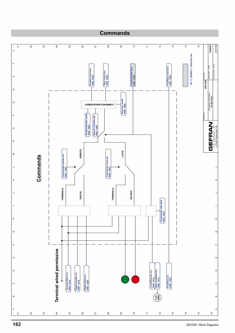
16� ADV200 • Block Diagrams
CommandsCom
man
ds
01 02 03 04 05 06 07 08 09 10 11 12 13 14 15 16
01 02 03 04 05 06 07 08 09 10 11 12 13 14 15
AB
CD
EF
GH
IJ
KL
MN
OP
QR
ST
U
AB
CD
EF
GH
IJ
KL
Term
inal
wire
dpe
rmis
sive
DIG
ITAL
KEY
PAD
Enab
lecm
dm
onPA
R10
24
Star
tcm
dm
onPA
R10
26
Fast
Stop
cmd
mon
PAR
1028
LOC
REM
Fast
Stop
src
PAR
1022
COMMANDSMANAGEMENT
Enab
le/d
isab
lem
ode
PAR
1004
Spee
d0
disa
ble
dly
PAR
1006
TERM
INALS
Dig
ital
En
ab
lesrc
PA
R1018
Term
inal
Sta
rtsrc
PA
R1016
Dig
ital
Sta
rtsrc
PA
R1020
RE
MO
TE
Co
mm
an
ds
rem
ote
sel
PA
R1000
TE
RM
INA
LS
LO
CA
L
Co
mm
an
ds
local
R1002
sel
PA
Lo
cal/R
em
ote
src
PA
R1014
Dig
Lo
cal/R
em
ote
PA
R1012
Lo
cal/re
mo
tem
on
PA
R1030
Co
mm
an
ds
safe
sta
rt
PA
R1010
Sto
pkey
mo
de
PA
R1008
AD
V200
19/0
2/0
7
Filena
me:
Issued
Date---
Initials:
RevisionDate--Initials:
Prop
rieta
ryIn
form
atio
nD
oN
ot
Co
py
PRODUCT:
Via
Car
ducc
i,24
I-210
40Geren
zano
VA
On
“L
_D
IGS
EL
1”
sele
cti
on
list
22/01/08
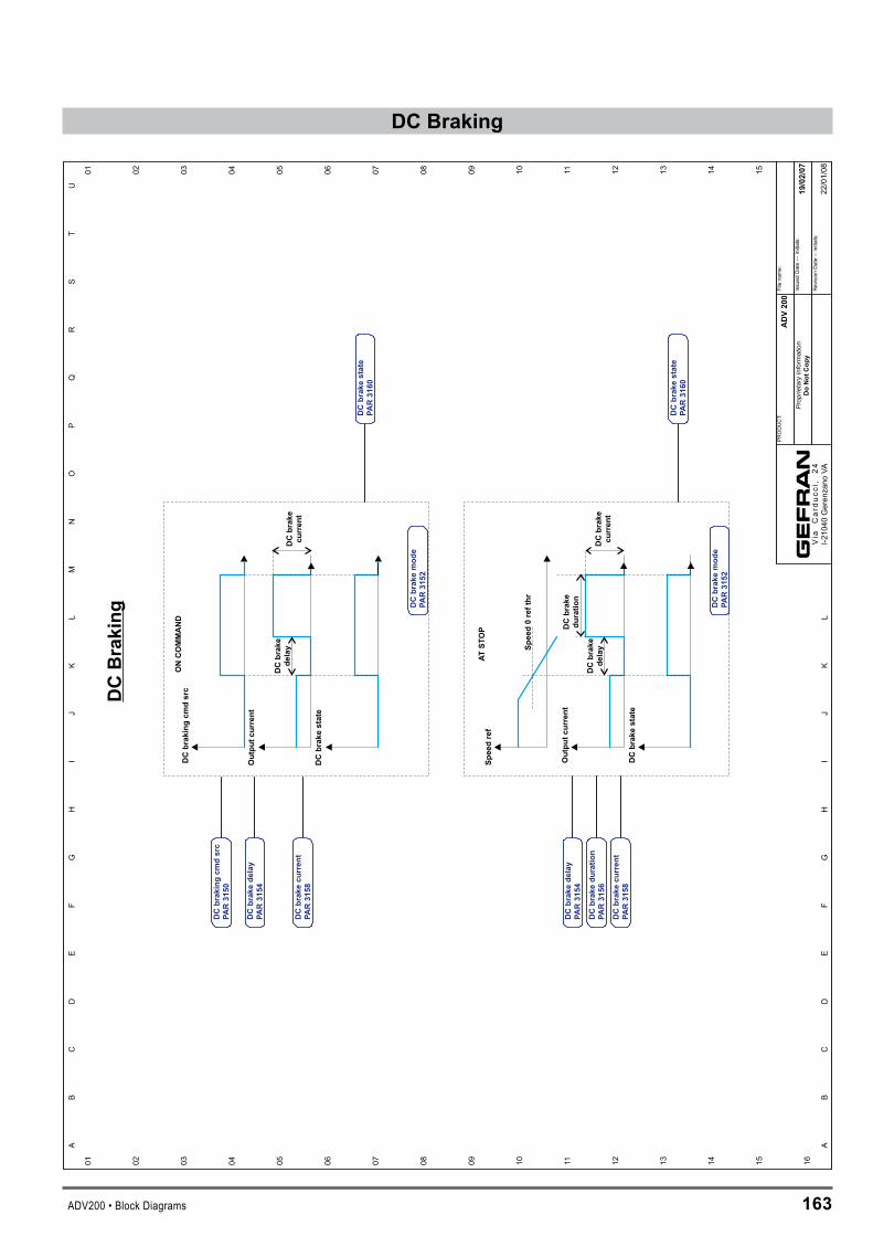
ADV200 • Block Diagrams 16�
DCBraking
DCbrake
current
Speed0refthr
DCbrake
delay
DCbrake
current
Speedref
Outputcurrent
DCbrakestate
DCbrake
duration
DCbrake
delay
DCbrakingcm
dsrc
Outputcurrent
DCbrakestate
ATSTOP
ONCOMMAND
DCBraking
01 02 03 04 05 06 07 08 09 10 11 12 13 14 15 16
01 02 03 04 05 06 07 08 09 10 11 12 13 14 15
AB
CD
EF
GH
IJ
KL
MN
OP
QR
ST
U
AB
CD
EF
GH
IJ
KL
DCbrakemode
PAR3152
DCbrakedelay
PAR3154
DCbrakeduration
PAR3156
DCbrakecurrent
PAR3158
DCbrakestate
PAR3160
DCbrakemode
PAR3152
DCbrakestate
PAR3160
DCbrakingcm
dsrc
PAR3150
DCbrakedelay
PAR3154
DCbrakecurrent
PAR3158
ADV200
19/02/07
Filena
me:
Issued
Date---
Initials:
RevisionDate--Initials:
Prop
rieta
ryIn
form
atio
nDoNotCopy
PRODUCT:
Via
Car
ducc
i,24
I-210
40Geren
zano
VA22
/01/08
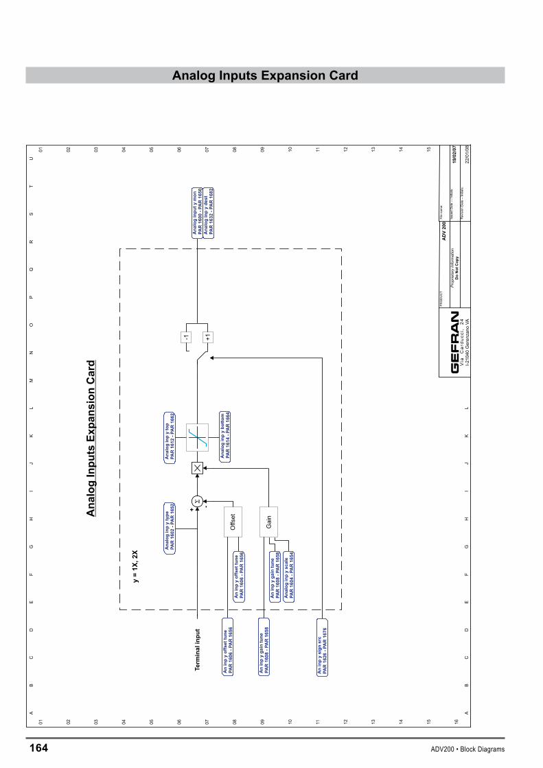
164 ADV200 • Block Diagrams
AnalogInputsExpansionCard
+ -+1-1
y=1X
,2X
Offset
GainAnalogInputsEx
pansionCard
01 02 03 04 05 06 07 08 09 10 11 12 13 14 15 16
01 02 03 04 05 06 07 08 09 10 11 12 13 14 15
AB
CD
EF
GH
IJ
KL
MN
OP
QR
ST
U
AB
CD
EF
GH
IJ
KL
Term
inalinpu
t
Analoginpytype
PAR1602
-PAR1652
Aninpyoffsettune
PAR1606
-PAR1656
Aninpyoffsettune
PAR1606
-PAR1656
Aninpygaintune
PAR1608
-PAR1658
An
tune
PAR1608
-PAR1658
inpygain
Analoginpyscale
PAR1604
-PAR1654
Analoginpybotto
mPA
R1614
-PAR1664
Analoginpytop
PAR1612
-PAR1662
Analoginputy
mon
PAR1600
-PAR1650
Analoginpydest
PAR1632
-PAR1682
Aninpysign
src
PAR1626
-PAR1676
ADV200
19/02/07
Filename:
Issued
Date---
Initials:
RevisionDate--Initials:
Prop
rieta
ryIn
form
atio
nDoNot
Copy
PRODUCT:
Via
Car
ducc
i,24
I-210
40Geren
zano
VA22
/01/08
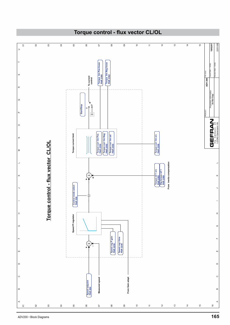
ADV200 • Block Diagrams 165
Torque control - flux vector CL/OL
T
SpeedPI
regu
lator
+ +
Torque
curren
tlim
it
Tocu
rren
tco
ntrol
0F
+ -
From
inertia
compe
nsation
Torque
control-
fluxvector
CL/OL
01 02 03 04 05 06 07 08 09 10 11 12 13 14 15 16
01 02 03 04 05 06 07 08 09 10 11 12 13 14 15
AB
CD
EF
GH
IJ
KL
MN
OP
QR
ST
U
AB
CD
EF
GH
IJ
KL
SpeedregPga
inPA
R2236
SpeedregItim
ePA
R2238
Torque
ref1
src
PAR2382
Dig
torque
ref1
PAR2380
Con
trol
mod
eselect
PAR556
Torque
currlim
src
PAR2358
Torque
currlim
Pos
PAR2350
Torque
currlim
Neg
PAR2352
Torque
currlim
sel
PAR2354
Torque
limPo
sInus
ePA
R2360
Torque
limNeg
Inus
ePA
R2362
Start/S
top
From
Gainad
apt
Speedsetpoint
PAR664
Measu
redsp
eed
ADV200
19/02/07
Filename:
Issued
Date---
Initials:
RevisionDate--Initials:
Prop
rieta
ryIn
form
atio
nDoNot
Cop
y
PRODUCT:
Via
Car
ducc
i,24
I-21040
Gerenzano
VA22/01/08

166 ADV200 • Block Diagrams
ControlV/F
Slip
comp
Measu
redsp
eed
01 02 03 04 05 06 07 08 09 10 11 12 13 14 15 16
01 02 03 04 05 06 07 08 09 10 11 12 13 14 15
AB
CD
EF
GH
IJ
KL
MN
OP
QR
ST
U
AB
CD
EF
GH
IJ
KL
Speedsetpoint
PAR664
Slip
compfilter
PAR2442
Slip
comp
PAR2440
Slip
Igain
PAR2448
Slip
Pga
inPA
R2446
Slip
compmod
ePA
R2444
ADV200
19/02/07
Filename:
Issued
Date---
Initials:
RevisionDate--Initials:
Prop
rieta
ryIn
form
atio
nDoNot
Cop
y
PRODUCT:
Via
Car
ducc
i,24
I-21040
Gerenzano
VA22/01/08
Vflim
itVf
curve
Con
trol
V/F
Torque
limPo
sInus
ePA
R2360
Torque
limNeg
Inus
ePA
R2362
Torque
currlim
Pos
PAR2350
Torque
currlim
Neg
PAR2352
Torque
currlim
sel
PAR2354
Volta
gebo
ost
PAR2400
Vfvo
ltage
1PA
R2410
Vfvo
ltage
PAR2406
Vffreq
uenc
y1
PAR2412
Vffreq
uenc
yPA
R2408
Vfscalesrc
PAR2492
Dig
Vfscale
PAR2490
Volta
gebo
ostg
ain
PAR2402
Vfsh
ape
PAR2430
Vfcu
rren
tlim
Itim
ePA
R2362
Vfcu
rren
tlim
Ptim
ePAR2460
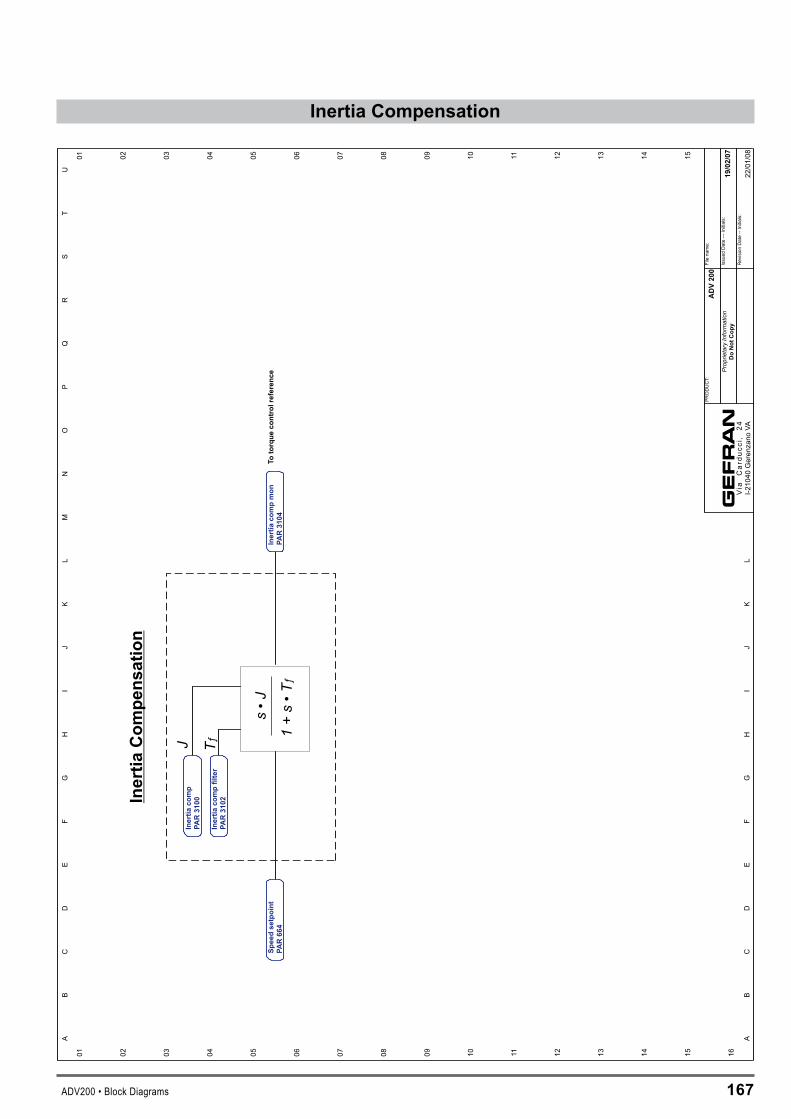
ADV200 • Block Diagrams 167
InertiaCompensation
Totorque
controlreferen
ces
•J
1+
s•
Tƒ
TƒJ
Inertia
Com
pens
ation
01 02 03 04 05 06 07 08 09 10 11 12 13 14 15 16
01 02 03 04 05 06 07 08 09 10 11 12 13 14 15
AB
CD
EF
GH
IJ
KL
MN
OP
QR
ST
U
AB
CD
EF
GH
IJ
KL
Inertia
compfilter
PAR31
02
Inertia
comp
PAR31
00
Inertia
compmon
PAR31
04Sp
eedse
tpoint
PAR66
4
ADV20
0
19/02/07
Filena
me:
Issued
Date---
Initials:
RevisionDate--Initials:
Pro
prie
tary
Info
rma
tio
nDoNot
Cop
y
PRODUCT:
Via
Car
ducc
i,24
I-210
40Geren
zano
VA22
/01/08

16� ADV200 • Block Diagrams
Compare
I I
| |
12
12
12
12
= != |=|
||!=
||
I I
II
II
| |
I I12
12
12
12
< > |<|
||>
||
I I
II
II
Com
pare
01 02 03 04 05 06 07 08 09 10 11 12 13 14 15 16
01 02 03 04 05 06 07 08 09 10 11 12 13 14 15
AB
CD
EF
GH
IJ
KL
MN
OP
QR
ST
U
AB
CD
EF
GH
IJ
KL
Com
pare
inpu
t1src
PAR36
60Dig
c1
Pom
pare
inpu
tAR36
50
Com
pare
inpu
t2src
PAR36
62Dig
compa
reinpu
t2PA
R36
52
Com
pare
func
tion
PAR36
70
Com
pare
delay
PAR36
74
Com
pare
output
PAR36
76
Com
pare
windo
wPA
R36
72
ADV20
0
19/02/07
Filena
me:
Issued
Date---
Initials:
RevisionDate--Initials:
Prop
rieta
ryIn
form
atio
nDoNot
Cop
y
PRODUCT:
Via
Car
ducc
i,24
I-210
40Geren
zano
VA22
/01/08
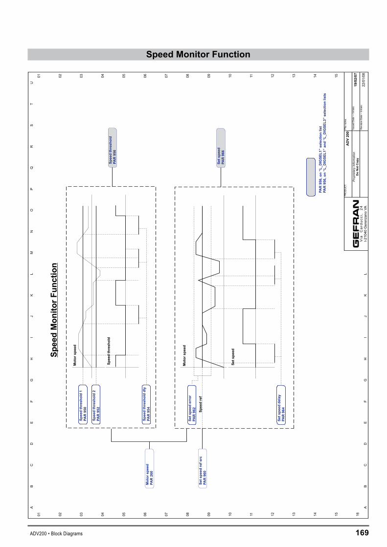
ADV200 • Block Diagrams 169
SpeedMonitorFunctionS
pe
ed
Mo
nit
or
Fu
nc
tio
n
01 02 03 04 05 06 07 08 09 10 11 12 13 14 15 16
01 02 03 04 05 06 07 08 09 10 11 12 13 14 15
AB
CD
EF
GH
IJ
KL
MN
OP
QR
ST
U
AB
CD
EF
GH
IJ
KL
Sp
eed
thre
sh
old
1
PA
R950
Sp
eed
thre
sh
old
2
PA
R952
Sp
eed
thre
sh
old
dly
PA
R954
Mo
tor
sp
eed
Sp
eed
thre
sh
old
Sp
eed
thre
sh
old
PA
R956
Set
sp
eed
err
or
PA
R962
Mo
tor
sp
eed
Set
sp
eed
Set
sp
eed
ref
src
PA
R960
Set
sp
eed
PA
R966
Set
sp
eed
dela
y
PA
R964
Sp
eed
ref
Mo
tor
sp
eed
PA
R260
AD
V200
19/0
2/0
7
Filena
me:
Issued
Date---
Initials:
RevisionDate--Initials:
Prop
rieta
ryIn
form
atio
nD
oN
ot
Co
py
PRODUCT:
Via
Car
ducc
i,24
I-210
40Geren
zano
VA
PA
R956,
on
“L
_D
IGS
EL
1”
sele
cti
on
list
PA
R956,
on
“L
_D
IGS
EL
1”
an
d“L
_D
IGS
EL
3”
sele
cti
on
lists
22/01/08

170 ADV200 • Block Diagrams
Droop
Droop
01 02 03 04 05 06 07 08 09 10 11 12 13 14 15 16
01 02 03 04 05 06 07 08 09 10 11 12 13 14 15
AB
CD
EF
GH
IJ
KL
MN
OP
QR
ST
U
AB
CD
EF
GH
IJ
KL
Droop
outm
onPA
R3070
Droop
limit
PAR3064
Droop
filter
PAR3062
Droop
gain
PAR3060
+ -
Droop
refsrc
PAR3052
Torque
ref
PAR2386
ADV200
19/02/07
Filena
me:
Issued
Date---
Initials:
RevisionDate--Initials:
Prop
rieta
ryIn
form
atio
nDoNot
Cop
y
PRODUCT:
Via
Car
ducc
i,24
I-210
40Geren
zano
VA

ADV200 • Block Diagrams 171
Powerloss
Pow
erlo
ss
01 02 03 04 05 06 07 08 09 10 11 12 13 14 15 16
01 02 03 04 05 06 07 08 09 10 11 12 13 14 15
AB
CD
EF
GH
IJ
KL
MN
OP
QR
ST
U
AB
CD
EF
GH
IJ
KL
Spee
dse
tpoi
ntPA
R66
4
Mot
orsp
eed
PAR
260
Toto
rque
cont
rol
Pow
erlo
ssne
xtra
tioPA
R34
46
Pow
erlo
ssra
mpd
own
PAR
3442
Pow
erlo
ssm
ain
src
PAR
3440
Pow
erlo
ssIt
ime
PAR
3422
Pow
erlo
ssac
celt
ime
PAR
3402
Pow
erlo
ssde
celt
ime
PAR
3404
Pow
erlo
ssfu
nctio
nPA
R34
00Po
wer
loss
Pga
inPA
R34
20
Pow
erlo
ssne
xtac
tive
PAR
3448
Volta
gede
tect
Pow
erlo
ssm
ode
PAR
3438
AD
V20
0
19/0
2/07
Filena
me:
Issued
Date---
Initials:
RevisionDate--Initials:
Prop
rieta
ryIn
form
atio
nD
oN
otC
opy
PRODUCT:
Via
Car
ducc
i,24
I-210
40Geren
zano
VA
Para
met
ers
notp
rese
nton
men
ues


Manu
aleA
DV20
0FP
-EN
Rev.
0.0 -
1-9-
2008
1S9H
51
Gef
ran
wo
rld
wid
e
GEFRAN S.p.A.Via Sebina 7425050 Provaglio d’Iseo (BS) ITALYPh. +39 030 98881Fax +39 030 [email protected]
Drive & Motion Control UnitVia Carducci 2421040 Gerenzano [VA] ITALYPh. +39 02 967601Fax +39 02 [email protected]
GEFRAN BENELUXLammerdries, 14AB-2250 OLENPh. +32 (0) 14248181Fax. +32 (0) [email protected]
GEFRAN BRASILELETROELETRÔNICAAvenida Dr. Altino Arantes,377/379 Vila Clementino04042-032 SÂO PAULO - SPPh. +55 (0) 1155851133Fax +55 (0) [email protected]
GEFRAN DEUTSCHLANDPhilipp-Reis-Straße 9a63500 SELIGENSTADTPh. +49 (0) 61828090Fax +49 (0) [email protected]
GEFRAN SUISSE SARue Fritz Courvoisier 402302 La Chaux-de-FondsPh. +41 (0) 329684955Fax +41 (0) [email protected]
GEFRAN - FRANCE4, rue Jean Desparmet - BP 823769355 LYON Cedex 08Ph. +33 (0) 478770300Fax +33 (0) [email protected]
GEFRAN INCAutomation and Sensors8 Lowell AvenueWINCHESTER - MA 01890Toll Free 1-888-888-4474Ph. +1 (781) 7295249Fax +1 (781) [email protected]
GEFRAN INCMotion Control14201 D South Lakes DriveNC 28273 - CharlottePh. +1 704 3290200Fax +1 704 3290217salescontact@sieiamerica.
SIEI AREG - GERMANYZachersweg, 17D 74376 - GemmrigheimPh. +49 7143 9730Fax +49 7143 [email protected]
GEFRAN SIEI - UK Ltd.7 Pearson Road, Central ParkTELFORD, TF2 9TX Ph. +44 (0) 845 2604555Fax +44 (0) 845 [email protected]
GEFRAN SIEI - ASIABlk. 30 Loyang way 03-19 Loyang Industrial Estate 508769 SINGAPORE Ph. +65 6 8418300 Fax. +65 6 7428300 [email protected]
GEFRAN SIEI ElectricBlock B, Gr.Flr, No.155, Fu Te Xi Yi Road,Wai Gao Qiao Trade Zone 200131 ShanghaiPh. +86 21 5866 7816Ph. +86 21 5866 [email protected]
GEFRAN SIEI DRIVES TECHNOLOGYNo.1265, B1, Hong De Road,Jia Ding District201821 ShanghaiPh. +86 21 69169898Fax +86 21 [email protected]
Technical Assistance : [email protected]
Customer Service : [email protected]. +39 02 96760500Fax +39 02 96760278