adsc/caltrans cidh pile workshop spring 2008 1 overview of structural design and detailing of large...
TRANSCRIPT

ADSC/CALTRANS CIDH Pile Workshop Spring 2008
1
Overview of Structural Design and Detailing
of Large Diameter Drilled Shafts (Caltrans Practice)
Amir M. Malek, PE, PhDSenior Bridge Engineer (Technical Specialist)
Office of Bridge Design Services
California Department of Transportation

ADSC/CALTRANS CIDH Pile Workshop Spring 2008
2
Outline• Types of Large Diameter Shafts and Comparison • Design Highlights and Review of LRFD
Requirements • Communications of Structural and Geotechnical
Designers for LRFD of Shafts • Highlights of Seismic Design and Detailing
Requirements per Caltrans Seismic Design Criteria (SDC)
• Case Study

ADSC/CALTRANS CIDH Pile Workshop Spring 2008
3
Applications and Types
• Used for high seismic loads also where small footprint is desirable
• Most effective where hard layer (rock) is reachable
• Used with/without casing
• Types I & II per SDC classification
Type-I : More ductile performance, advantageous for short columns
Type-II : Easier post-event repair, shaft enlargement of at least 18” (24” under study) to contain inelastic action to the column (SDC 7.7.3.5)

ADSC/CALTRANS CIDH Pile Workshop Spring 2008
4
Test of 6’ diameter Type-I Shaft at UCLA

ADSC/CALTRANS CIDH Pile Workshop Spring 2008
5
Test of 6’ diameter Type-I Shaft at UCLA

ADSC/CALTRANS CIDH Pile Workshop Spring 2008
6
Types of Large Diameter Drilled Shafts (Caltrans SDC)

ADSC/CALTRANS CIDH Pile Workshop Spring 2008
7
LRFD & Seismic Design Highlights• Structural Designer provides Factored Loads for applicable
Limit States • Geotechnical Designer will provide tip elevations based on
Compression, Tension, and Settlement also Factored Nominal Resistance for Service, Strength and Extreme Event Limit States (LRFD)
• Structural Designer performs Stability Analysis and provides tip elevation for Lateral Loads
• Structural Designer analyzes, designs and details the shaft for Seismic Demands according to Caltrans SDC
• Scour, Liquefaction and Lateral Spreading are considered in design (if applicable)

ADSC/CALTRANS CIDH Pile Workshop Spring 2008
8
Review of LRFD Requirements
• Consider Service, Strength and Extreme Event Limit States for Geotechnical and Structural Design of the Shaft
• Follow MTD3-1 for Communications and Transfer of Information between SD and GS as summarized in the following Tables

ADSC/CALTRANS CIDH Pile Workshop Spring 2008
9
Preliminary Design Data Sheet(to be provided by SD)

ADSC/CALTRANS CIDH Pile Workshop Spring 2008
10
General Foundation Information(to be provided by SD)

ADSC/CALTRANS CIDH Pile Workshop Spring 2008
11
Foundation Design Loads(to be provided by SD)
ADSC/CALTRANS CIDH Pile Workshop Spring 2008
12
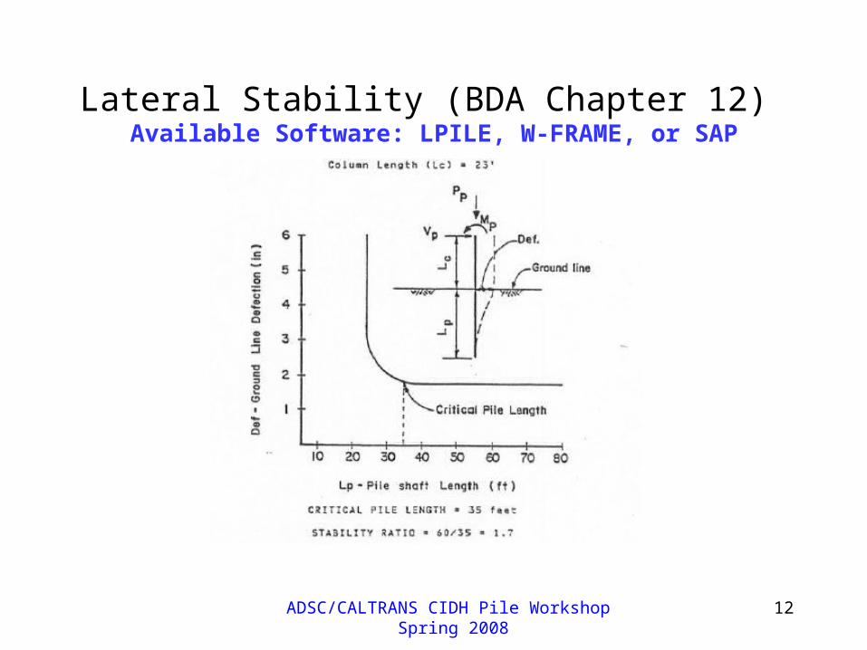
Lateral Stability (BDA Chapter 12) Available Software: LPILE, W-FRAME, or SAP

ADSC/CALTRANS CIDH Pile Workshop Spring 2008
13
General Seismic Design Highlights (Requirements that may be affected by size/type of the shaft)
• Geometrical/Structural Irregularities
• Demand and Capacity
• P-Δ Effect
• Displacement Ductility Limitation
• Minimum Local Displacement Ductility Capacity

ADSC/CALTRANS CIDH Pile Workshop Spring 2008
14
• Geometrical/Structural Irregularities: Balanced Stiffness of Bents (SDC 7.1.1) Balanced Frame Geometry (SDC 7.1.2)
• Demand vs. Capacity (SDC 4.1.1)• P-Δ Effect (SDC 4.2)• Displacement Ductility Demand Limits (1.5-3/5
for bents supported by the shafts, per SDC 2.2.3)• Minimum Local Displacement Ductility Capacity
Limits (SDC 3.1.4.1)

ADSC/CALTRANS CIDH Pile Workshop Spring 2008
15
Structural Analysis for Demand Assessment
• Use Expected Material Properties
• Determine Column/Shaft Plastic Moments from Section Analysis
• Use Mo=1.2Mp
• Use Push-over Analysis and Find Shear and Moment Demands at Collapse
ADSC/CALTRANS CIDH Pile Workshop Spring 2008
16
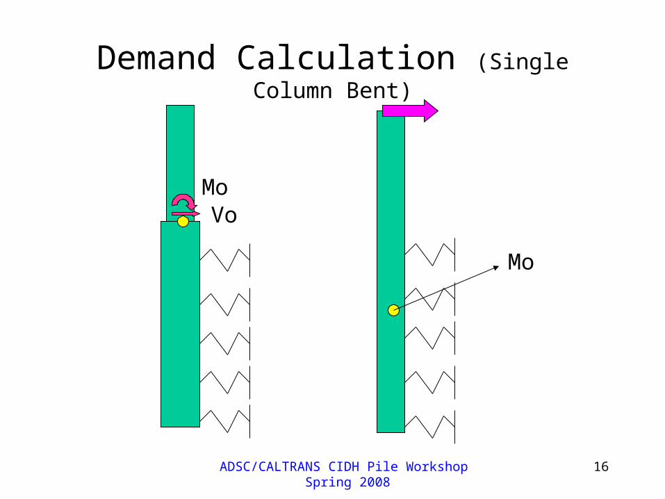
Demand Calculation (Single Column Bent)
MoVo
Mo

ADSC/CALTRANS CIDH Pile Workshop Spring 2008
17
Seismic Demand Calculation (Multi-Column Bent)
Type-I
Mo

ADSC/CALTRANS CIDH Pile Workshop Spring 2008
18
Seismic Demand Calculation (Multi-Column Bent)
Type-II
Mo

ADSC/CALTRANS CIDH Pile Workshop Spring 2008
19
Structural Design of the Shafts
• MneType II >= 1.25 MDemand (SDC 7.7.3.2)
• VnType II >= VDemand (SDC 3.6.7)
• Shear capacity is calculated as a ductile member using SDC 3.6 requirements (for Type-II assume µd=1)

ADSC/CALTRANS CIDH Pile Workshop Spring 2008
20
Detailing Requirements
• No Splice Zones (SDC 8.1.1)
Plastic hinge region and areas of MD>My
• Ultimate Splices (SDC 8.1.2) Ductile members outside “No Splice Zone”• Service Splice (MTD20-9) Capacity Protected Members like Bent Cap • For Hoops and Spirals in Ductile Members Use Ultimate
Splices, Except: No splices in spirals used in “No Splice Zones” (end
anchorage has been used to improve constructability)

ADSC/CALTRANS CIDH Pile Workshop Spring 2008
21
Case Study (Type-II)
Top of the Pile Boundary Conditions:V & M (V=150 kips, M=3,750 k-ft)

ADSC/CALTRANS CIDH Pile Workshop Spring 2008
22
Liquefied Layer

ADSC/CALTRANS CIDH Pile Workshop Spring 2008
23
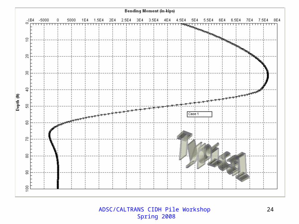
ADSC/CALTRANS CIDH Pile Workshop Spring 2008
24

ADSC/CALTRANS CIDH Pile Workshop Spring 2008
25

ADSC/CALTRANS CIDH Pile Workshop Spring 2008
26

ADSC/CALTRANS CIDH Pile Workshop Spring 2008
27
Case-I Results Competent Not Liquefied
Liquefied (I)
Liquefied (II)
Top Deflection (in.)
0.92 3.4 9.8
12.2
14.4
18.2
Mmax (kip-in.)
(x10-4)
5.3 6.5 7.6
9.2
9.4
11.5
Location of Mmax (ft)
7 14 32
37
42
42
Vmax (kips) 320 268 420
517
420
519
Location of Vmax (ft)
17 32 50
50
55
57
Stable Length (ft)
34 54 65 75
Scour Included

ADSC/CALTRANS CIDH Pile Workshop Spring 2008
28
Summary (Method-I)

ADSC/CALTRANS CIDH Pile Workshop Spring 2008
29

ADSC/CALTRANS CIDH Pile Workshop Spring 2008
30
Thank You