adjustable single weight lifting machine - pmu.edu.sa · adjustable single weight lifting machine...
TRANSCRIPT
1
College of Engineering
Department of Mechanical Engineering
Spring 2016-17
Senior Design Project Report
Adjustable Single Weight Lifting Machine
In partial fulfillment of the requirements for the
Degree of Bachelor of Science in Mechanical Engineering
Team Members
Student Name Student ID
1 Abdul Aziz AlBaker 201301005
2 Mohammed AlZahrani 201000224
3 Mohammed Al Quraisha 201200633
4 Abdulla Fenais 201102616
Project Advisors: Dr. Ragu Raman
Advisor Name: Dr. Nader Sawalhi
Adjustable Single Weight Lifting Machine – PMU/ME
2
Abstract
This project is very helpful because Weight lifting sport is the most popular sport among
bodybuilders and fitness trainers. Most weight lifting machines contains lots of metal weights to
have adjustable weights for the trainers which makes it heavy and expensive. This project will be
done by a group of engineering students who have thought of how this problem could be solved
using physics theory, a design has been prepared to build an advanced light weight lifting
machine that works with one weight bar and give the trainer an adjustable weight from 5 to 80kg.
This project shall be in the domain: A body building machine that can be implemented in gyms
designed for weightlifters works with one weight bar. This project enables us to make an easier
to change weights, cheaper, lighter, and a less space equipper weight lifting machine.
Acknowledgment
This project was done under the supervision of Prince Mohammed bin Fahad University,
Khobar, Saudi Arabia. Many Thanks go to the Mechanical Engineering Department which
prepared us to be qualified mechanical engineers and gave us all the tools needed to serve our
community well and contribute our best in the industry. We especially extend our appreciation to
our advisor Dr. RaguramanKannan and co-advisor: Dr. Nader AlSawalhi for teaching, helping,
and supporting us in our senior project. Their valuable comments and feedbacks helped us to
improve the quality of our senior project. Besides that, we express our gratitude to our out of
campus consultant Eng. Ahmad AlShammari, Saudi Aramco Employee, who had kept
supporting us during the whole semester regarding any manufacturing advice.
Adjustable Single Weight Lifting Machine – PMU/ME
3
List of Tables
Table 1 (Different Ratio Forces) .................................................................................................................. 26
Table 2 (Testing Subsystem 1) .................................................................................................................... 35
Table 3 (Project Plan) .................................................................................................................................. 41
Table 4 (Group Contribution) ...................................................................................................................... 43
Table 5 (Challenges) .................................................................................................................................... 44
Table 6 (Detailed BOM) ............................................................................................................................... 45
List of Figures
Figure 1 (Horizontal Seated Leg Press) ....................................................................................................... 10
Figure 2 (Lat Pull-Down) .............................................................................................................................. 11
Figure 3(Cable Biceps Bar) .......................................................................................................................... 11
Figure 4(Cable Triceps Bar) ......................................................................................................................... 12
Figure 5(Chest Press) .................................................................................................................................. 12
Figure 6(Rowing Machine) .......................................................................................................................... 13
Figure 7(Fixed Pulley) .................................................................................................................................. 16
Figure 8(Movable Pulley) ............................................................................................................................ 16
Figure 9 (Practical compound pulley) ......................................................................................................... 17
Figure 10 (Bicycle Gears) ............................................................................................................................. 18
Figure 11 (Rear Bicycle Gears) .................................................................................................................... 19
Figure 12 (Bicycle Gears) ............................................................................................................................. 19
Figure 13 (Bicycle Gears) ............................................................................................................................. 20
Figure 14 (Bicycle Chain) ............................................................................................................................. 20
Figure 15 (System Basic Design) ................................................................................................................. 24
Figure 16 (System Basic Design) ................................................................................................................. 25
Figure 17 (Mechanism) ............................................................................................................................... 26
Figure 18 (Driver and Driven) ...................................................................................................................... 27
Figure 19(System Components) .................................................................................................................. 27
Figure 20(System Components) .................................................................................................................. 30
Figure 21 (Lifting Arm & Driver Cone) ......................................................................................................... 34
Figure 22 (Testing Lifting Arm & Driver Cone) ............................................................................................ 35
Figure 23 (Driven Cone& Weight Bar)......................................................................................................... 36
Figure 24 (Testing Driven Cone& Weight Bar) ............................................................................................ 37
Figure 25 (Driver & Driven Cones) .............................................................................................................. 37
Figure 26 (Testing Driver & Driven Cones) .................................................................................................. 38
Figure 27 (Overall Testing) .......................................................................................................................... 38
Figure 28 (Actual Cost Analysis) .................................................................................................................. 44
Adjustable Single Weight Lifting Machine – PMU/ME
4
Table of Content
Abstract ......................................................................................................................................................... 2
Acknowledgment .......................................................................................................................................... 2
List of Tables ................................................................................................................................................. 3
Chapter 1: Introduction ................................................................................................................................ 7
1.1 Project definition ................................................................................................................................. 7
1.2 Project Objective ................................................................................................................................. 7
Chapter 2: Literature Review ...................................................................................................................... 10
2.1 Background ....................................................................................................................................... 10
2.2 Previous Work .................................................................................................................................. 13
2.3 Pulley ................................................................................................................................................ 15
2.4 Bicycle Gears .................................................................................................................................... 17
2.5 Aluminum ......................................................................................................................................... 21
Chapter 3: System Design ........................................................................................................................... 23
3.1 Design Constrains ............................................................................................................................. 23
3.2 Design Methodology ......................................................................................................................... 24
3.3 Product Subsystems and Components .............................................................................................. 27
3.4 Implementation ................................................................................................................................. 32
Chapter 4: System Testing and Analysis ..................................................................................................... 34
4.1 Subsystem 1 (Lifting Arm & Driver Cone) ...................................................................................... 34
4.2 Subsystem 2 (Driven Cone& Weight Bar) ................................................................................. 36
4.3 Subsystem 3 (Driver & Driven Cones) ....................................................................................... 37
4.4 Overall Results, Analysis and Discussion ................................................................................... 38
Chapter 5: Project Management ................................................................................................................ 41
5.1 Project Plan ................................................................................................................................. 41
5.2 Contribution of Team Members .................................................................................................. 43
5.3 Project Execution Monitoring ..................................................................................................... 43
5.4 Challenges and Decision Making ............................................................................................... 44
5.5 Project Bill of Materials and Budget ........................................................................................... 44
Adjustable Single Weight Lifting Machine – PMU/ME
5
Chapter 6: Project Analysis ......................................................................................................................... 47
6.1 Lifelong Learning ............................................................................................................................ 47
6.2 Impact of Engineering Solutions ..................................................................................................... 47
Chapter 7: Conclusions and Future Recommendations ............................................................................. 48
7.1 Conclusions ....................................................................................................................................... 48
7.2 Future Recommendations ........................................................................................................... 48
References .................................................................................................................................................. 49
Appendix A: Part Drawings ......................................................................................................................... 50
Adjustable Single Weight Lifting Machine – PMU/ME
6
CHAPTER 1
Introduction & Project Objectives
Adjustable Single Weight Lifting Machine – PMU/ME
7
Chapter 1: Introduction
1.1 Project definition
Bodybuilding sport is highly diffused between people in all ages starting from 16 years old; to
play this sport and start building muscles heavy weights should be lifted. Bodybuilders don’t
have the same power to lift the same weights; it depends on their strength, energy and
experience. In order to give the trainer adjustable weights to make him or her choose the proper
weight a lot of metal should be used in the training machine either for the weights them self or
for the other components to hold the weights. These machines are so heavy, expensive, occupy a
lot of space and are hard to be moved from a location to another. As a group of mechanical
Engineering students we thought of a solution for this problem, The Single Weight Adjustable
Weight Lifting Machine is the solution. Single Weight Adjustable Weight Lifting Machine is a
machine that allows the trainer to lift between 5kg to 80kg by using one weight bar of 20kg only.
The concept design of this machine was adopted from the idea of bicycle gears. Depending on
the gears ratio the load on the user will change from lower to higher to make him or her feel the
difference in the work they apply to train.
1.2 Project Objective
1.2.1 Inventing a New Idea Replaces the Physical Weight Addition Method:
The main objective of building an “Adjustable Weight Lifting Machine” is to find a new idea of
changing the weight rather than the traditional one which we have in gyms nowadays. The
system will be designed based on different gear ratio concept; the new mechanism enables the
user to play with 1:4 ratios to increase or decrease the exercising weight.
1.2.2 Decrease the Cost of Manufacturing:
For one individual machine it may not look feasible to use an adjustable lifting machine depends
on gear ratio concept instead of applying different physical weights, however when we look at
Adjustable Single Weight Lifting Machine – PMU/ME
8
the idea from a mass production view, we notice that it will save a lot of money.
1.2.3 Lightweight machines which can be carried everywhere:
Machines which we see in gyms around the world are difficult to be moved from one place to
another because of the weights attached with the set. Even if we dismantle the exercise machine,
we will need to put extra efforts to carry the weights separately; which will take more time.
However the new system will be much lighter and easy to carry everywhere.
1.2.4 Avoid injuries which may occur while changing the weight:
Using this concept will decrease the chance of hand injuries which may be caused by the
frequent applying of the machine weight. In the traditional method, the trainee needs to change
the weight pin in each set which is very close to the arrayed weights; the trainee finger may get
stuck in between the weights, or any other people who is nearby the lifted weights. However in
the new approach everything will be covered and away from any touch which causes injuries.
1.2.5 Decrease the Space Used for Gym Equipment:
Weightlifting equipment occupies most spaces in gym centers, which is a disadvantage
especially to small space places. This project aims to build a smaller machine, with high
performance. So we can save more space to be utilized in other things.
Adjustable Single Weight Lifting Machine – PMU/ME
9
CHAPTER 2
Literature Review
Adjustable Single Weight Lifting Machine – PMU/ME
10
Chapter 2: Literature Review
2.1 Background
2.1.1 Sport types and exercise mechanism
As we know the sports activities are very important to anyone and we can do the exercise
everywhere. Such as, exercise at home, at work, and at Gym. In this project we bring a new
concept where anyone can change the weight and train with little effort. We created a light
weight lifting machine that varies the weight between light and heavy without the need of
changing weights.
There are seven types of machines that can be used for lifting Weight. Each one of us can have
his own plan and daily activity from the network or any institute. But, unfortunately without
certified trainer and programming director that can have side effect injury and no benefit from
this program. We study 7 Gym Machines for Weight lifting. Figures 1 to 7 show some examples.
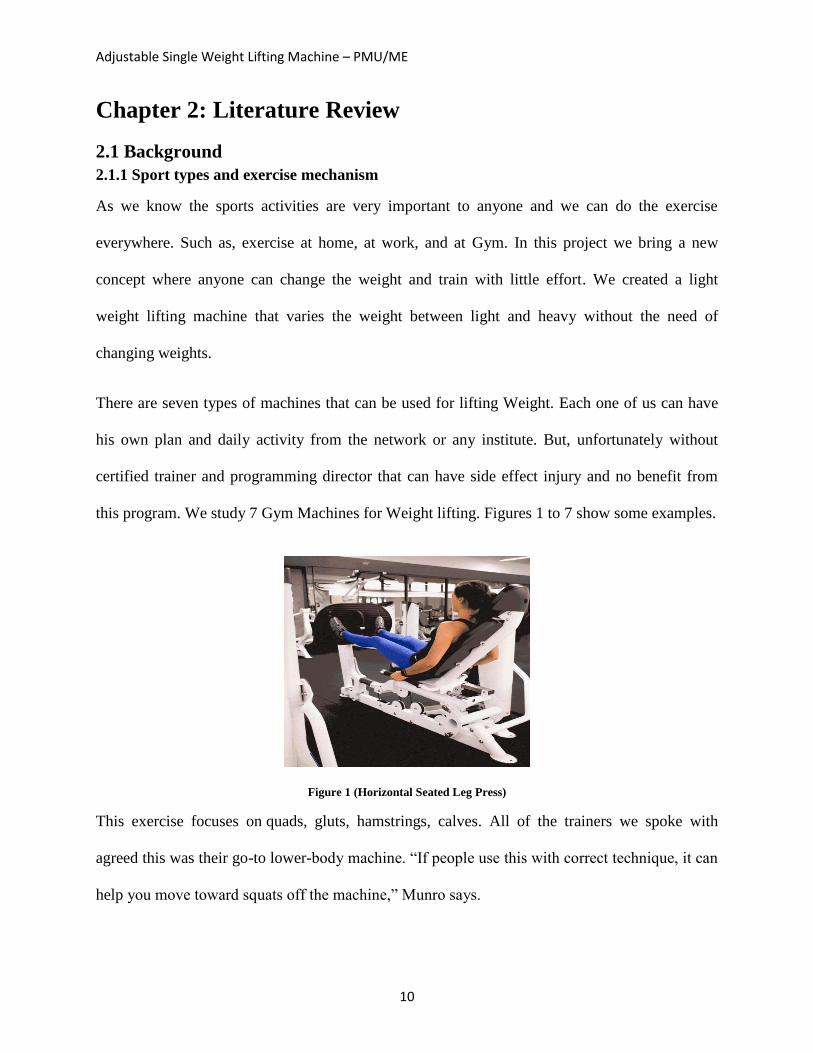
Figure 1 (Horizontal Seated Leg Press)
This exercise focuses on quads, gluts, hamstrings, calves. All of the trainers we spoke with
agreed this was their go-to lower-body machine. “If people use this with correct technique, it can
help you move toward squats off the machine,” Munro says.
Adjustable Single Weight Lifting Machine – PMU/ME
11
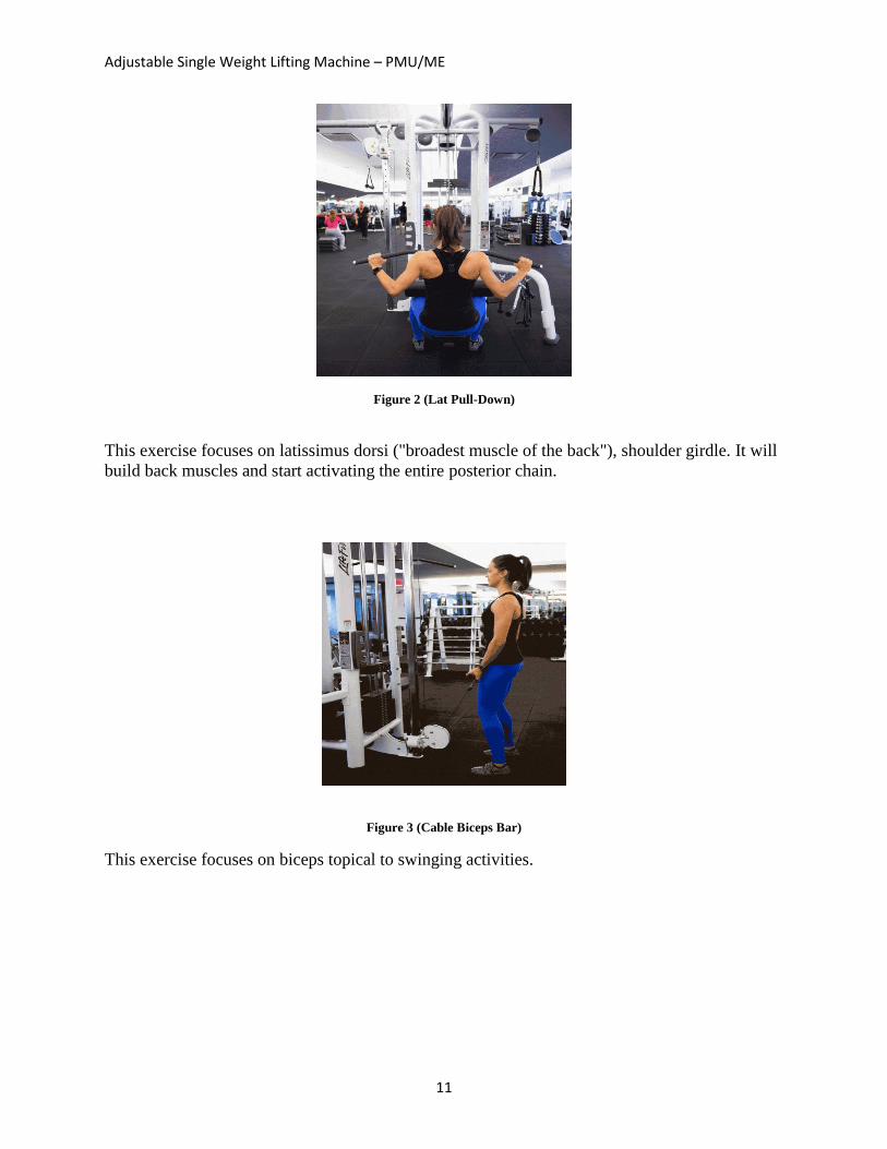
Figure 2 (Lat Pull-Down)
This exercise focuses on latissimus dorsi ("broadest muscle of the back"), shoulder girdle. It will
build back muscles and start activating the entire posterior chain.
Figure 3 (Cable Biceps Bar)
This exercise focuses on biceps topical to swinging activities.
Adjustable Single Weight Lifting Machine – PMU/ME
12
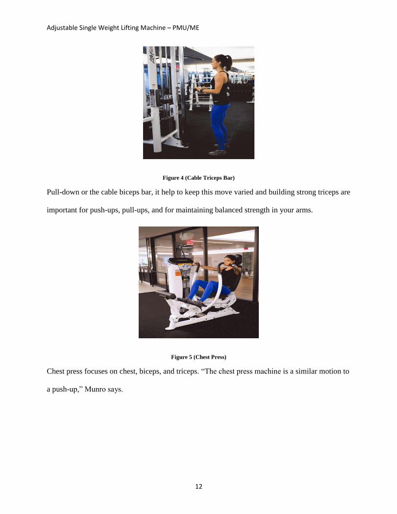
Figure 4 (Cable Triceps Bar)
Pull-down or the cable biceps bar, it help to keep this move varied and building strong triceps are
important for push-ups, pull-ups, and for maintaining balanced strength in your arms.
Figure 5 (Chest Press)
Chest press focuses on chest, biceps, and triceps. “The chest press machine is a similar motion to
a push-up,” Munro says.
Adjustable Single Weight Lifting Machine – PMU/ME
13
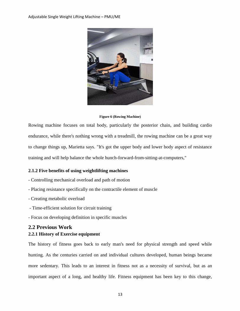
Figure 6 (Rowing Machine)
Rowing machine focuses on total body, particularly the posterior chain, and building cardio
endurance, while there's nothing wrong with a treadmill, the rowing machine can be a great way
to change things up, Marietta says. "It's got the upper body and lower body aspect of resistance
training and will help balance the whole hunch-forward-from-sitting-at-computers,"
2.1.2 Five benefits of using weightlifting machines
- Controlling mechanical overload and path of motion
- Placing resistance specifically on the contractile element of muscle
- Creating metabolic overload
- Time-efficient solution for circuit training
- Focus on developing definition in specific muscles
2.2 Previous Work
2.2.1 History of Exercise equipment
The history of fitness goes back to early man's need for physical strength and speed while
hunting. As the centuries carried on and individual cultures developed, human beings became
more sedentary. This leads to an interest in fitness not as a necessity of survival, but as an
important aspect of a long, and healthy life. Fitness equipment has been key to this change,
Adjustable Single Weight Lifting Machine – PMU/ME
14
helping generations of people from around the world to shape and condition their bodies.
2.2.2 Machines Types
Resistance Machines
After the development of free weights, it took hundreds of years for a major advancement in
resistance training to occur. In the 1950s, American fitness guru Jack Leanne invented several
pieces of equipment that have been widely used ever since. Leanne developed the first cable-
pulley machine, the Smith machine and the first leg extensions machine. The mechanical
principles behind these three pieces of equipment can be found in equipment in gyms around the
world.
Cardiovascular Equipment
The most popular piece of cardiovascular exercise equipment, the treadmill, was first introduced
in 1875, but it wasn't used for exercise, it was used for manufacturing. In 1952, University of
Washington in Seattle doctor Robert A. Bruce began using treadmills for human stress tests. This
inspired businessmen to turn the treadmill into a consumer exercise device that would allow
someone to run or jog naturally while staying in place. By the 1960s, treadmills were common in
homes and gyms. Elliptical machines, which are similar in function to treadmills but place less
stress on the lower body, were first released in the mid-1990s and have rivaled treadmills in
popularity ever since.
Resistance Bands
Resistance bands, which are essentially strips of elastic that create progressive resistance as they
are stretched, were first used by former football coach Dick Hartzell for functional training in
1980. Since then, manufacturers have modified resistance bands by attaching handles and
creating anchors that allow resistance bands to mimic almost any gym exercise that can be
performed with free weights, but without the bulk, making them much more portable than free
Adjustable Single Weight Lifting Machine – PMU/ME
15
weights.
2.3 Pulley
A pulley is a wheel with a section along its edge for holding a rope or link. It is a straightforward
machine that alters the course and purpose of utilization of a pulling power. Pulleys are generally
utilized as a part of sets intended to lessen the measure of drive expected to lift a heap. The
extent of compel is decreased; however it must act through a more drawn out separation.
Subsequently, the measure of work important for the heap to achieve a specific stature is the
same as the measure of work required without the pulleys.
History of Pulleys:
Just like the case with all the straightforward machines, the cause of the pulley is obscure. At the
point when early people groups lifted substantial protests by tossing vines or other unrefined
ropes over tree appendages, they utilized the possibility of a solitary settled pulley to alter the
course of a compel. Be that as it may, since there was no wheel to turn, this utilization brought
about extensive grating. It is trusted that by 1500 B.C.E. individuals in Mesopotamia utilized
rope pulleys for raising water.
Types of pulleys:
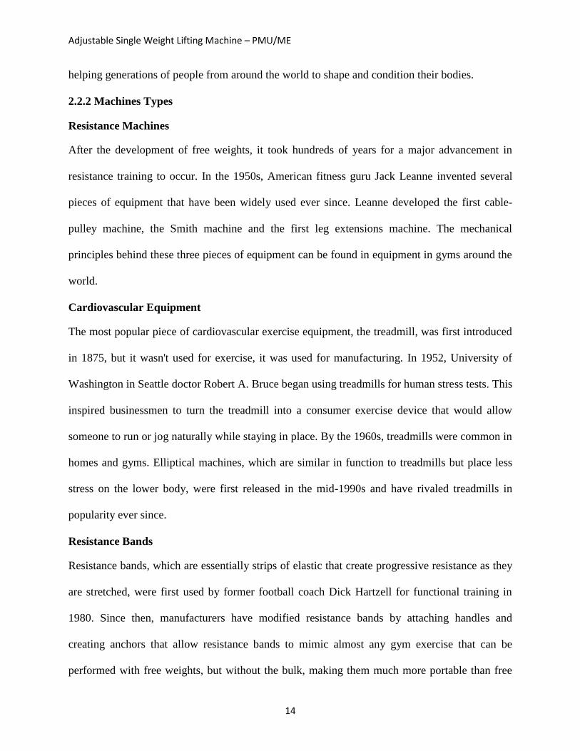
Fixed or class 1 pulley has a settled pivot. That is, the hub is "settled" or tied down set up. A
settled pulley is utilized to divert compel in a rope (called a belt when it goes in a full circle. A
settled pulley has a mechanical preferred standpoint of one.
Adjustable Single Weight Lifting Machine – PMU/ME
16
Figure 7 (Fixed Pulley)
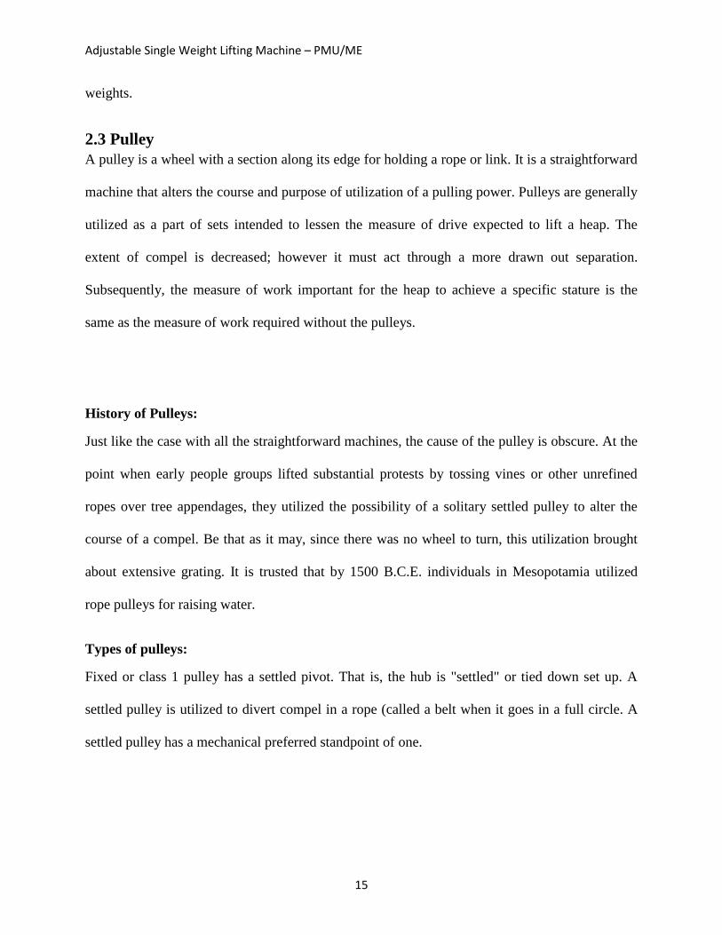
Movable or class II pulley has a free pivot. That is, the hub is "free" to move in space. A
portable pulley is utilized to change powers. A versatile pulley has a mechanical favorable
position of two. That is, whether one end of the rope is secured, pulling on the flip side of
the rope will apply a multiplied compel to the protest appended to the pulley.
Figure 8 (Movable Pulley)
Compound a compound pulley is a mix of fixed and movable pulley framework. Block
and tackle - A piece and handle is a compound pulley where a few pulleys are mounted on
Adjustable Single Weight Lifting Machine – PMU/ME
17
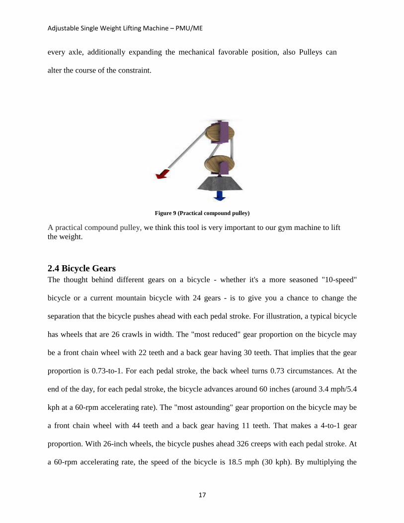
every axle, additionally expanding the mechanical favorable position, also Pulleys can
alter the course of the constraint.
Figure 9 (Practical compound pulley)
A practical compound pulley, we think this tool is very important to our gym machine to lift
the weight.
2.4 Bicycle Gears
The thought behind different gears on a bicycle - whether it's a more seasoned "10-speed"
bicycle or a current mountain bicycle with 24 gears - is to give you a chance to change the
separation that the bicycle pushes ahead with each pedal stroke. For illustration, a typical bicycle
has wheels that are 26 crawls in width. The "most reduced" gear proportion on the bicycle may
be a front chain wheel with 22 teeth and a back gear having 30 teeth. That implies that the gear
proportion is 0.73-to-1. For each pedal stroke, the back wheel turns 0.73 circumstances. At the
end of the day, for each pedal stroke, the bicycle advances around 60 inches (around 3.4 mph/5.4
kph at a 60-rpm accelerating rate). The "most astounding" gear proportion on the bicycle may be
a front chain wheel with 44 teeth and a back gear having 11 teeth. That makes a 4-to-1 gear
proportion. With 26-inch wheels, the bicycle pushes ahead 326 creeps with each pedal stroke. At
a 60-rpm accelerating rate, the speed of the bicycle is 18.5 mph (30 kph). By multiplying the
Adjustable Single Weight Lifting Machine – PMU/ME
18
accelerating rate to 120 rpm, the bicycle has a most extreme speed of 37 mph (60 kph). A scope
of 3.4 mph to 37 mph is awesome, and it gives the rider a chance to climb the steepest slope
gradually or race nearly as quick as an auto! That is the reason a bicycle has gears.
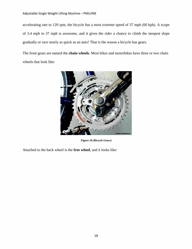
The front gears are named the chain wheels. Most bikes and motorbikes have three or two chain
wheels that look like:
Figure 10 (Bicycle Gears)
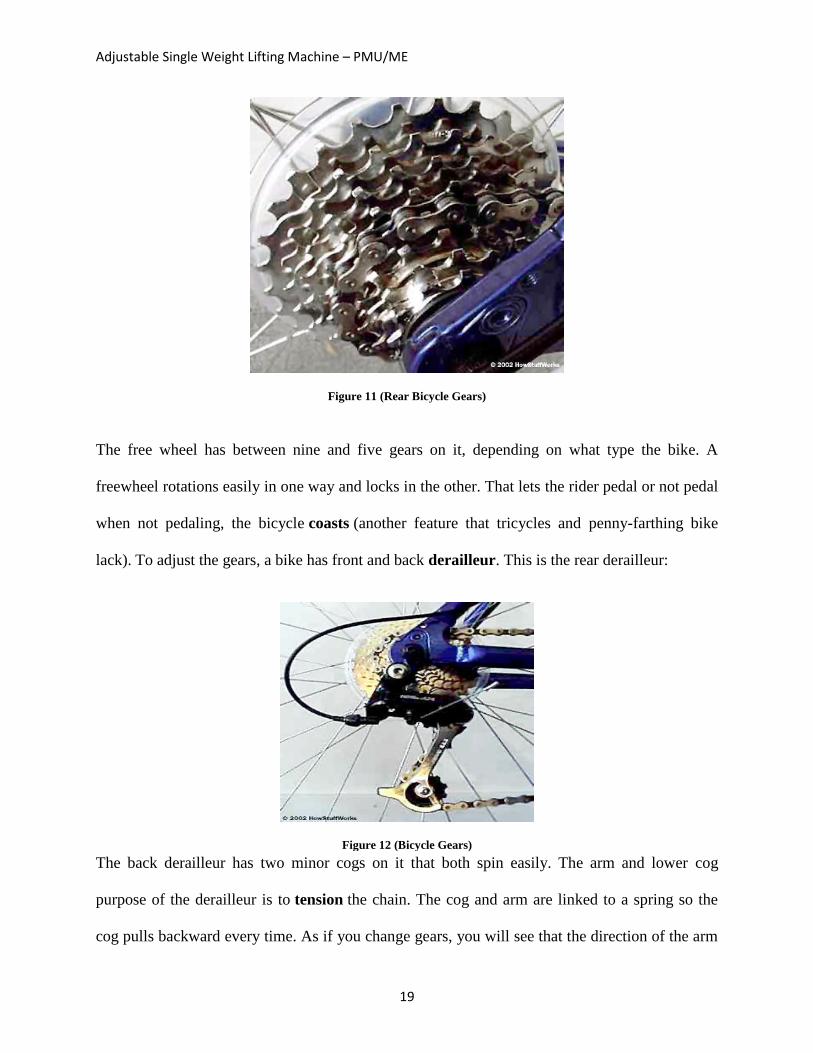
Attached to the back wheel is the free wheel, and it looks like:
Adjustable Single Weight Lifting Machine – PMU/ME
19
Figure 11 (Rear Bicycle Gears)
The free wheel has between nine and five gears on it, depending on what type the bike. A
freewheel rotations easily in one way and locks in the other. That lets the rider pedal or not pedal
when not pedaling, the bicycle coasts (another feature that tricycles and penny-farthing bike
lack). To adjust the gears, a bike has front and back derailleur. This is the rear derailleur:
Figure 12 (Bicycle Gears)
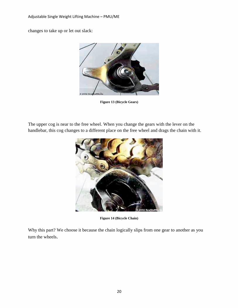
The back derailleur has two minor cogs on it that both spin easily. The arm and lower cog
purpose of the derailleur is to tension the chain. The cog and arm are linked to a spring so the
cog pulls backward every time. As if you change gears, you will see that the direction of the arm
Adjustable Single Weight Lifting Machine – PMU/ME
20
changes to take up or let out slack:
Figure 13 (Bicycle Gears)
The upper cog is near to the free wheel. When you change the gears with the lever on the
handlebar, this cog changes to a different place on the free wheel and drags the chain with it.
Figure 14 (Bicycle Chain)
Why this part? We choose it because the chain logically slips from one gear to another as you
turn the wheels.
Adjustable Single Weight Lifting Machine – PMU/ME
21
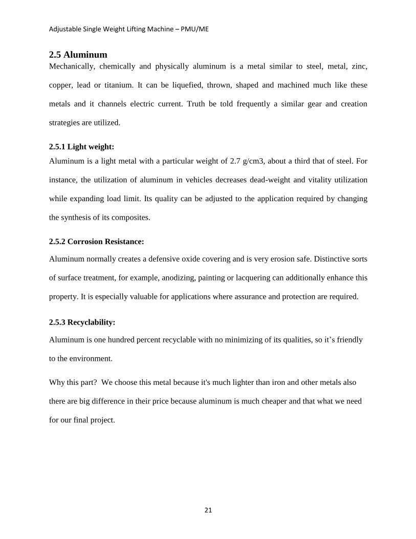
2.5 Aluminum
Mechanically, chemically and physically aluminum is a metal similar to steel, metal, zinc,
copper, lead or titanium. It can be liquefied, thrown, shaped and machined much like these
metals and it channels electric current. Truth be told frequently a similar gear and creation
strategies are utilized.
2.5.1 Light weight:
Aluminum is a light metal with a particular weight of 2.7 g/cm3, about a third that of steel. For
instance, the utilization of aluminum in vehicles decreases dead-weight and vitality utilization
while expanding load limit. Its quality can be adjusted to the application required by changing
the synthesis of its composites.
2.5.2 Corrosion Resistance:
Aluminum normally creates a defensive oxide covering and is very erosion safe. Distinctive sorts
of surface treatment, for example, anodizing, painting or lacquering can additionally enhance this
property. It is especially valuable for applications where assurance and protection are required.
2.5.3 Recyclability:
Aluminum is one hundred percent recyclable with no minimizing of its qualities, so it’s friendly
to the environment.
Why this part? We choose this metal because it's much lighter than iron and other metals also
there are big difference in their price because aluminum is much cheaper and that what we need
for our final project.
Adjustable Single Weight Lifting Machine – PMU/ME
22
CHAPTER 3
System Design
Adjustable Single Weight Lifting Machine – PMU/ME
23
Chapter 3: System Design
3.1 Design Constraints
Economically
One of the main objectives of our project is to reduce the cost of gym machines by reducing the
metals used in regular gym machines. In this case one of the constraints in our design is to
reduce the cost of manufacturing gym machines as low as possible. The following are some
points that should be under consideration in terms of the market of our project in future:
• Marketing analysis – size of market, distribution, market segments
• Design costs – design team computing, information retrieval
• Development costs – design detailing, supplier costs, testing costs
• Manufacturing cost - tooling, labor, overhead, assembly, inspection
• Distribution costs - packing, transport, service centers, spare parts, warranty
• Resources – time, budget, labor, capital, machines, material
Manufacturability
When the project is in the manufacturing level, there are a lot of things needed to be available.
The first thing is to find a factory to produce the project parts. Another thing is to make sure that
these parts can be purchased as spare parts if needed. Another thing to put it under consideration
is to find workshops or factories to assemble the parts together to produce the final machine.
Safety
As we all know, safety is always first. Our project consists of only one weight bar only so the
dangerous level in very lower than regular gym machines. But also there are some things should
be taken care of like the operational factors, for example the rotation movement of parts and the
Adjustable Single Weight Lifting Machine – PMU/ME
24
movement of other parts. All parts should be perfectly assembled to avoid injuries if a failure
accurse. .
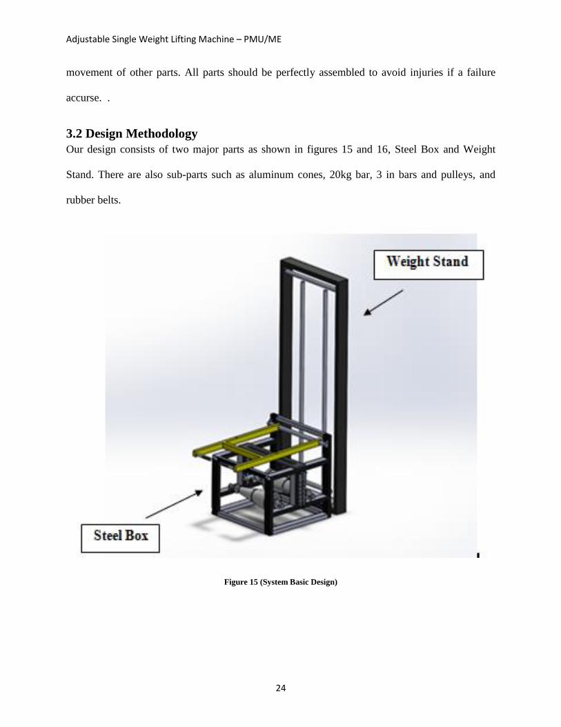
3.2 Design Methodology
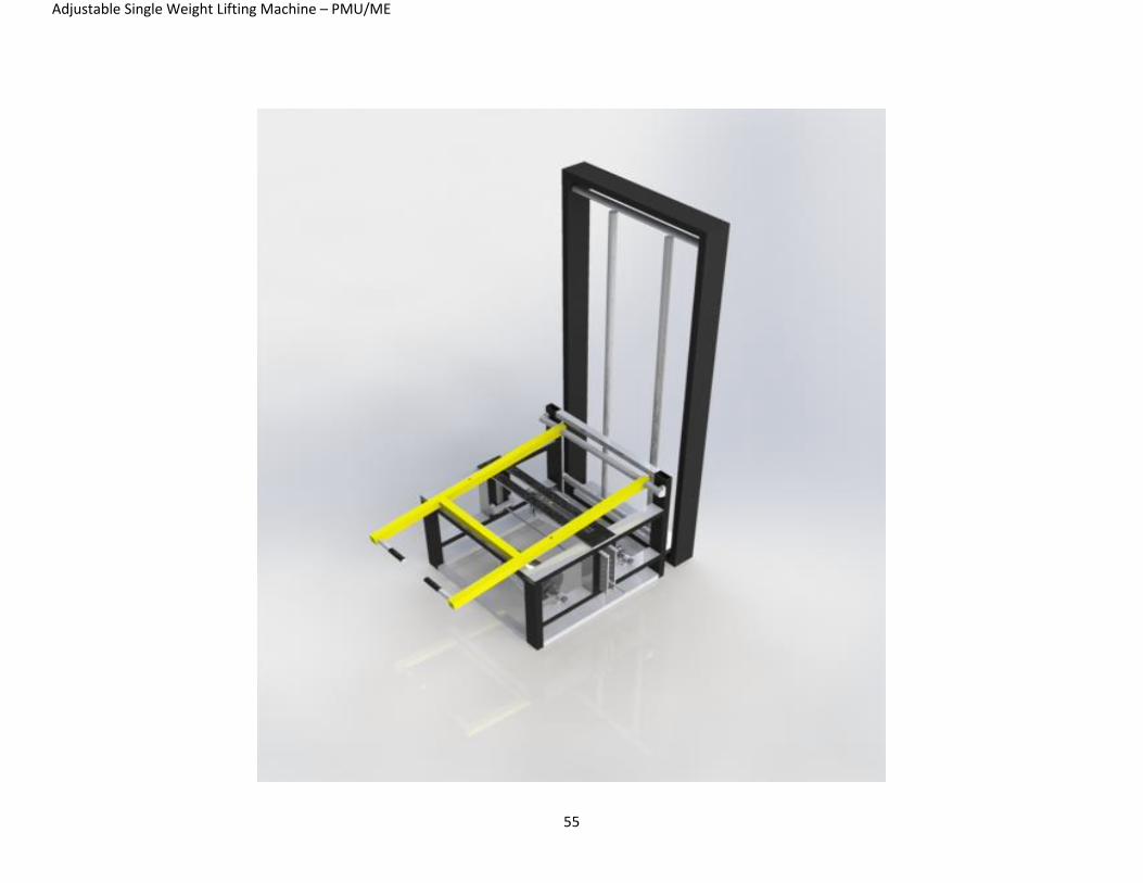
Our design consists of two major parts as shown in figures 15 and 16, Steel Box and Weight
Stand. There are also sub-parts such as aluminum cones, 20kg bar, 3 in bars and pulleys, and
rubber belts.
Figure 15 (System Basic Design)
Adjustable Single Weight Lifting Machine – PMU/ME
25
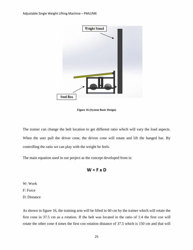
Figure 16 (System Basic Design)
The trainer can change the belt location to get different ratio which will vary the load aspects.
When the user pull the driver cone, the driven cone will rotate and lift the hanged bar. By
controlling the ratio we can play with the weight he feels.
The main equation used in our project as the concept developed from is:
W = F x D
W: Work
F: Force
D: Distance
As shown in figure 16, the training arm will be lifted in 60 cm by the trainer which will rotate the
first cone in 37.5 cm as a rotation. If the belt was located in the ratio of 1:4 the first con will
rotate the other cone 4 times the first con rotation distance of 37.5 which is 150 cm and that will
Adjustable Single Weight Lifting Machine – PMU/ME
26
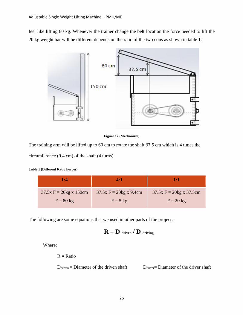
feel like lifting 80 kg. Whenever the trainer change the belt location the force needed to lift the
20 kg weight bar will be different depends on the ratio of the two cons as shown in table 1.
Figure 17 (Mechanism)
The training arm will be lifted up to 60 cm to rotate the shaft 37.5 cm which is 4 times the
circumference (9.4 cm) of the shaft (4 turns)
Table 1 (Different Ratio Forces)
1:4 4:1 1:1
37.5x F = 20kg x 150cm
F = 80 kg
37.5x F = 20kg x 9.4cm
F = 5 kg
37.5x F = 20kg x 37.5cm
F = 20 kg
The following are some equations that we used in other parts of the project:
R = D driven / D driving
Where:
R = Ratio
Ddriven = Diameter of the driven shaft Ddriver= Diameter of the driver shaft
Adjustable Single Weight Lifting Machine – PMU/ME
27
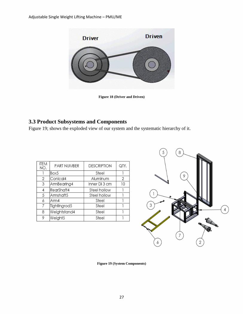
Figure 18 (Driver and Driven)
3.3 Product Subsystems and Components
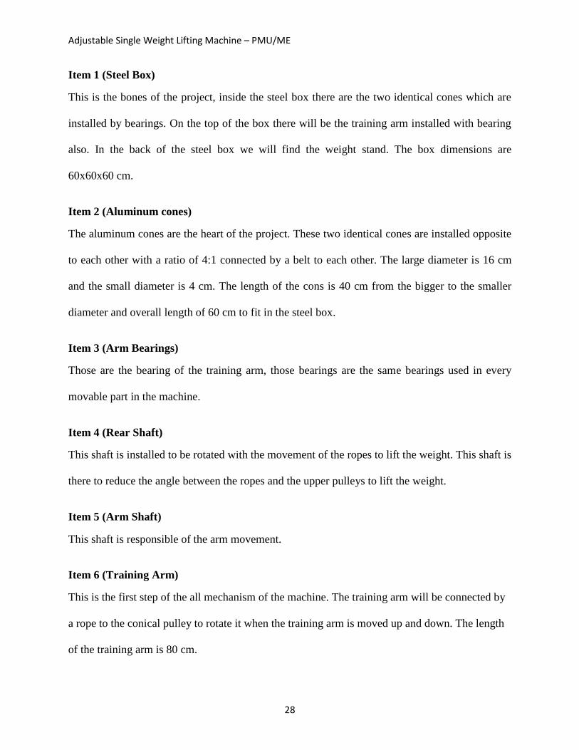
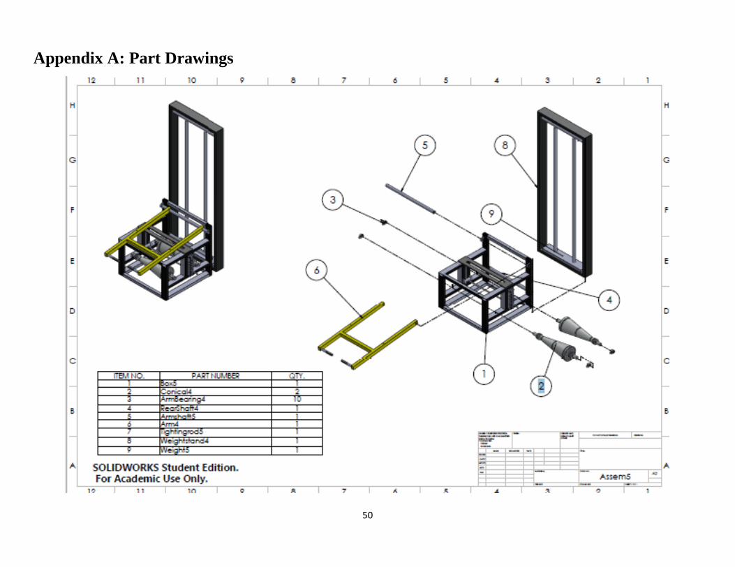
Figure 19; shows the exploded view of our system and the systematic hierarchy of it.
Figure 19 (System Components)
Adjustable Single Weight Lifting Machine – PMU/ME
28
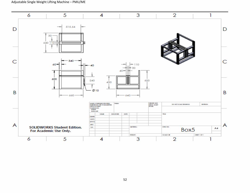
Item 1 (Steel Box)
This is the bones of the project, inside the steel box there are the two identical cones which are
installed by bearings. On the top of the box there will be the training arm installed with bearing
also. In the back of the steel box we will find the weight stand. The box dimensions are
60x60x60 cm.
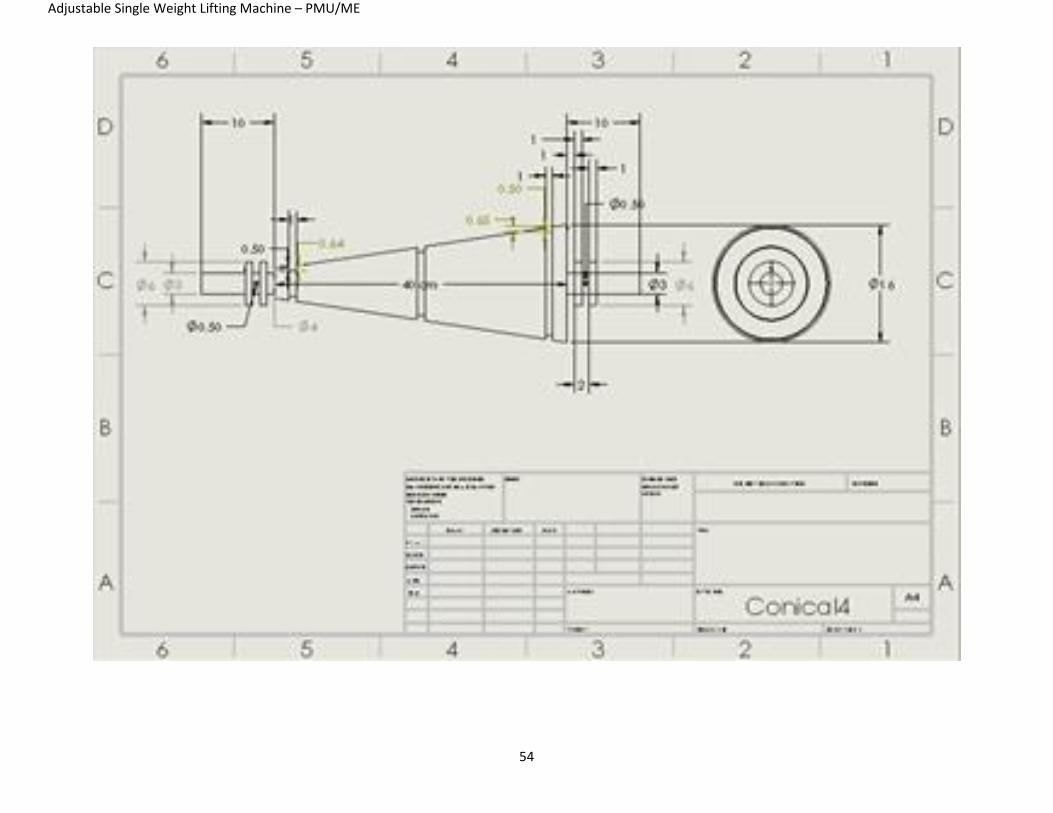
Item 2 (Aluminum cones)
The aluminum cones are the heart of the project. These two identical cones are installed opposite
to each other with a ratio of 4:1 connected by a belt to each other. The large diameter is 16 cm
and the small diameter is 4 cm. The length of the cons is 40 cm from the bigger to the smaller
diameter and overall length of 60 cm to fit in the steel box.
Item 3 (Arm Bearings)
Those are the bearing of the training arm, those bearings are the same bearings used in every
movable part in the machine.
Item 4 (Rear Shaft)
This shaft is installed to be rotated with the movement of the ropes to lift the weight. This shaft is
there to reduce the angle between the ropes and the upper pulleys to lift the weight.
Item 5 (Arm Shaft)
This shaft is responsible of the arm movement.
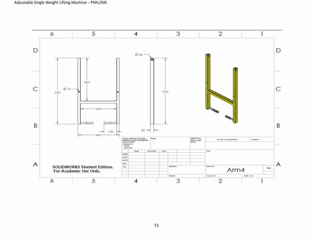
Item 6 (Training Arm)
This is the first step of the all mechanism of the machine. The training arm will be connected by
a rope to the conical pulley to rotate it when the training arm is moved up and down. The length
of the training arm is 80 cm.
Adjustable Single Weight Lifting Machine – PMU/ME
29
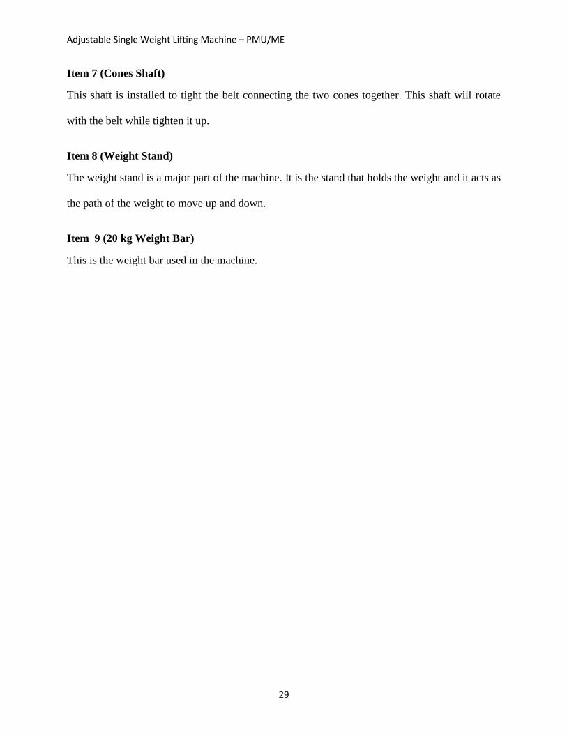
Item 7 (Cones Shaft)
This shaft is installed to tight the belt connecting the two cones together. This shaft will rotate
with the belt while tighten it up.
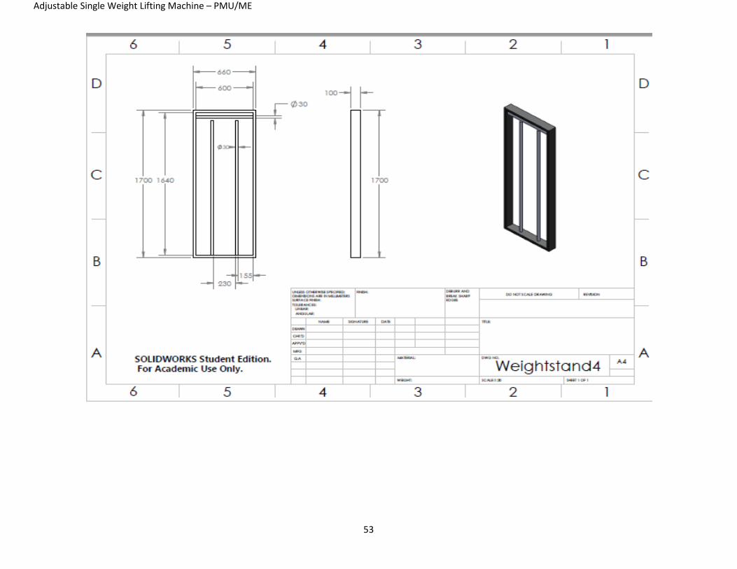
Item 8 (Weight Stand)
The weight stand is a major part of the machine. It is the stand that holds the weight and it acts as
the path of the weight to move up and down.
Item 9 (20 kg Weight Bar)
This is the weight bar used in the machine.
Adjustable Single Weight Lifting Machine – PMU/ME
30
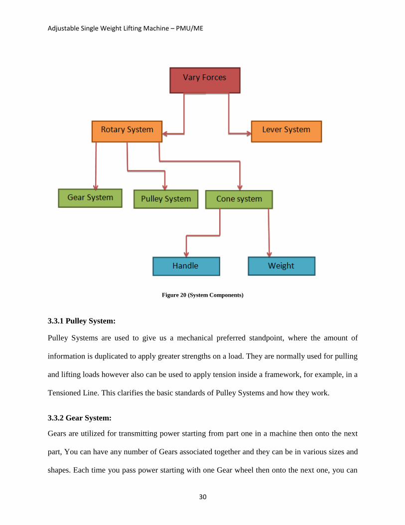
Figure 20 (System Components)
3.3.1 Pulley System:
Pulley Systems are used to give us a mechanical preferred standpoint, where the amount of
information is duplicated to apply greater strengths on a load. They are normally used for pulling
and lifting loads however also can be used to apply tension inside a framework, for example, in a
Tensioned Line. This clarifies the basic standards of Pulley Systems and how they work.
3.3.2 Gear System:
Gears are utilized for transmitting power starting from part one in a machine then onto the next
part, You can have any number of Gears associated together and they can be in various sizes and
shapes. Each time you pass power starting with one Gear wheel then onto the next one, you can
Adjustable Single Weight Lifting Machine – PMU/ME
31
do one of three things:
● Increase speed
● Increase force
● Change direction
But we're going to talk only about increase force because it’s the main idea about our project.
Increase force:
If the second wheel in a pair of gears is bigger than the first wheel, however the movement of the
gears will be slow but with more force.
Vary Force:
This is the main idea of our final project which is we don’t change the weight but we change the
force.
3.3.3 Rotary System:
Rotary system works by rotational motion to vary forces to decrease the force or increase it
without changing other functions such as the weight, material and size.
3.3.4 Lever System:
Lever, Simple System consisting of a rigid bar that rotates about a settled point, named a fulcrum
point. Levers effect the action, or force, expected to do a specific measure of work, and is
utilized to lift big objects. A lever makes work simpler by decreasing the force expected to move
a weight or load.

Adjustable Single Weight Lifting Machine – PMU/ME
32
3.3.5 Cone System:
The cone system is the system that we are going to use in our project, and it works by placed two
cones in opposite positions and connect them by a belt. Moreover, when we place the belt in the
right side the ratio is going to be 4 to 1 and the force will be high on the user to left the weight,
and if we place the belt in the left side the ratio is going to be 1 to 4 and the force will lower than
the first position. Furthermore, if we place the belt in the middle of the cones, the weight will be
equal to the force which is 20 kg.
3.4 Implementation
The following parts are available in the system:
1) Steel Box
a. Aluminum Cones (2 pcs)
b. Steel Shaft (2 pcs)
c. Pulleys ( 4 pcs)
2) Weight Stand
a. 20 kg bar
b. Steel Shaft
c. Pulleys (2 pcs)
There will be three rubber belts and a shaft installed horizontally in the steel box which allows
the user to tight the belt after choosing the appropriate belt location.
Adjustable Single Weight Lifting Machine – PMU/ME
33
CHAPTER 4
System Testing and Analysis
Adjustable Single Weight Lifting Machine – PMU/ME
34
Chapter 4: System Testing and Analysis
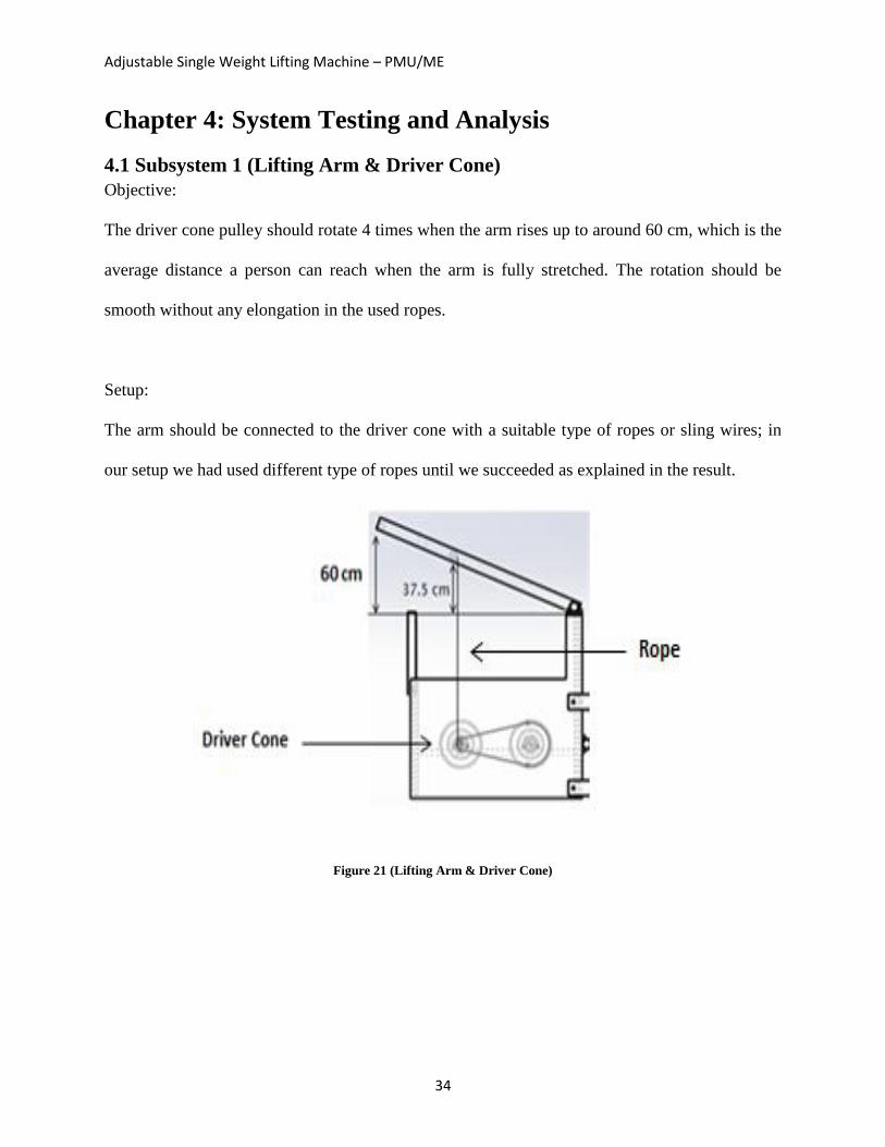
4.1 Subsystem 1 (Lifting Arm & Driver Cone)
Objective:
The driver cone pulley should rotate 4 times when the arm rises up to around 60 cm, which is the
average distance a person can reach when the arm is fully stretched. The rotation should be
smooth without any elongation in the used ropes.
Setup:
The arm should be connected to the driver cone with a suitable type of ropes or sling wires; in
our setup we had used different type of ropes until we succeeded as explained in the result.
Figure 21 (Lifting Arm & Driver Cone)
Adjustable Single Weight Lifting Machine – PMU/ME
35
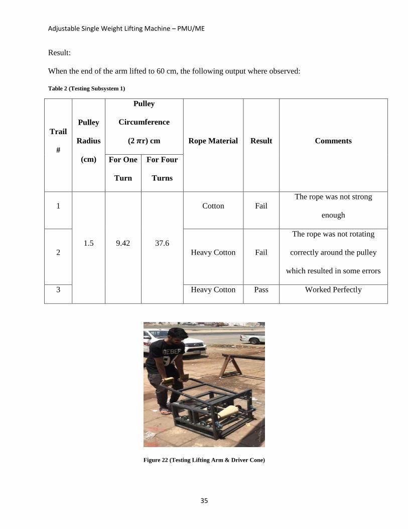
Result:
When the end of the arm lifted to 60 cm, the following output where observed:
Table 2 (Testing Subsystem 1)
Trail
#
Pulley
Radius
(cm)
Pulley
Circumference
(2 𝝅r) cm Rope Material Result Comments
For One
Turn
For Four
Turns
1
1.5 9.42 37.6
Cotton Fail
The rope was not strong
enough
2 Heavy Cotton Fail
The rope was not rotating
correctly around the pulley
which resulted in some errors
3 Heavy Cotton Pass Worked Perfectly
Figure 22 (Testing Lifting Arm & Driver Cone)
Adjustable Single Weight Lifting Machine – PMU/ME
36
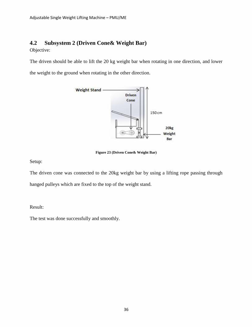
4.2 Subsystem 2 (Driven Cone& Weight Bar)
Objective:
The driven should be able to lift the 20 kg weight bar when rotating in one direction, and lower
the weight to the ground when rotating in the other direction.
Figure 23 (Driven Cone& Weight Bar)
Setup:
The driven cone was connected to the 20kg weight bar by using a lifting rope passing through
hanged pulleys which are fixed to the top of the weight stand.
Result:
The test was done successfully and smoothly.
Adjustable Single Weight Lifting Machine – PMU/ME
37
Figure 24 (Testing Driven Cone & Weight Bar)
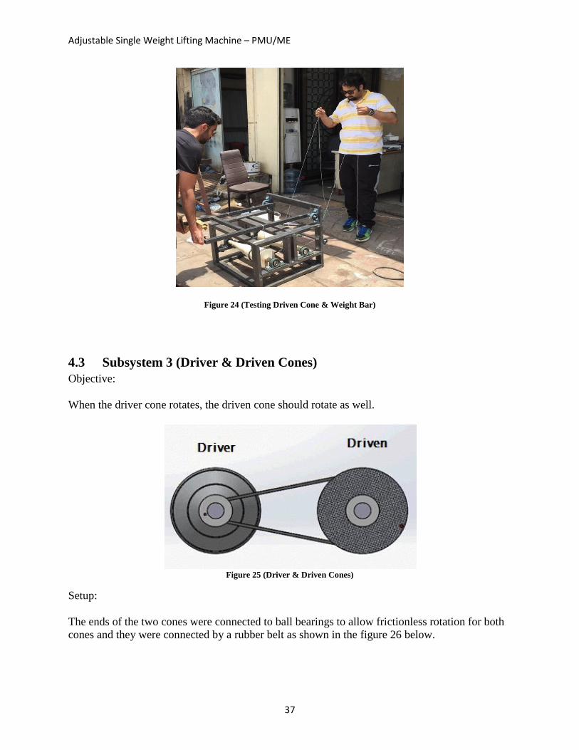
4.3 Subsystem 3 (Driver & Driven Cones)
Objective:
When the driver cone rotates, the driven cone should rotate as well.
Figure 25 (Driver & Driven Cones)
Setup:
The ends of the two cones were connected to ball bearings to allow frictionless rotation for both
cones and they were connected by a rubber belt as shown in the figure 26 below.
Adjustable Single Weight Lifting Machine – PMU/ME
38
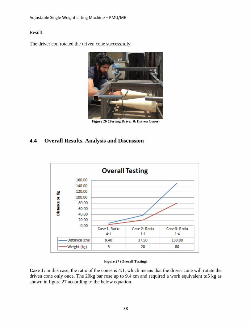
Result:
The driver con rotated the driven cone successfully.
Figure 26 (Testing Driver & Driven Cones)
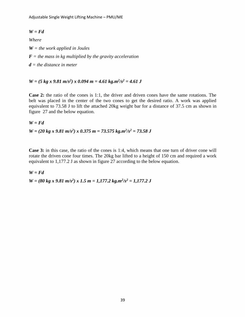
4.4 Overall Results, Analysis and Discussion
Figure 27 (Overall Testing)
Case 1: in this case, the ratio of the cones is 4:1, which means that the driver cone will rotate the
driven cone only once. The 20kg bar rose up to 9.4 cm and required a work equivalent to5 kg as
shown in figure 27 according to the below equation.
Adjustable Single Weight Lifting Machine – PMU/ME
39
W = Fd
Where
W = the work applied in Joules
F = the mass in kg multiplied by the gravity acceleration
d = the distance in meter
W = (5 kg x 9.81 m/s2) x 0.094 m = 4.61 kg.m2/s2 = 4.61 J
Case 2: the ratio of the cones is 1:1, the driver and driven cones have the same rotations. The
belt was placed in the center of the two cones to get the desired ratio. A work was applied
equivalent to 73.58 J to lift the attached 20kg weight bar for a distance of 37.5 cm as shown in
figure 27 and the below equation.
W = Fd
W = (20 kg x 9.81 m/s2) x 0.375 m = 73.575 kg.m2/s2 = 73.58 J
Case 3: in this case, the ratio of the cones is 1:4, which means that one turn of driver cone will
rotate the driven cone four times. The 20kg bar lifted to a height of 150 cm and required a work
equivalent to 1,177.2 J as shown in figure 27 according to the below equation.
W = Fd
W = (80 kg x 9.81 m/s2) x 1.5 m = 1,177.2 kg.m2/s2 = 1,177.2 J
Adjustable Single Weight Lifting Machine – PMU/ME
40
CHAPTER 5
Project Management
Adjustable Single Weight Lifting Machine – PMU/ME
41
Chapter 5: Project Management
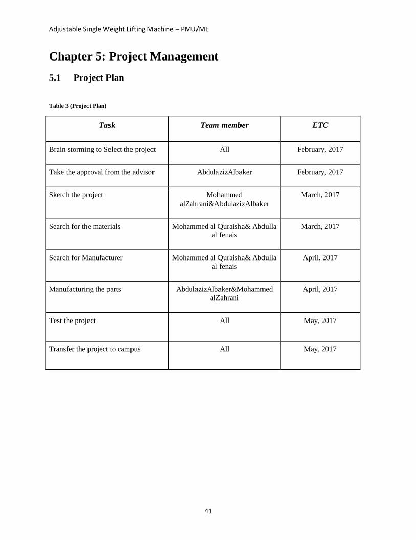
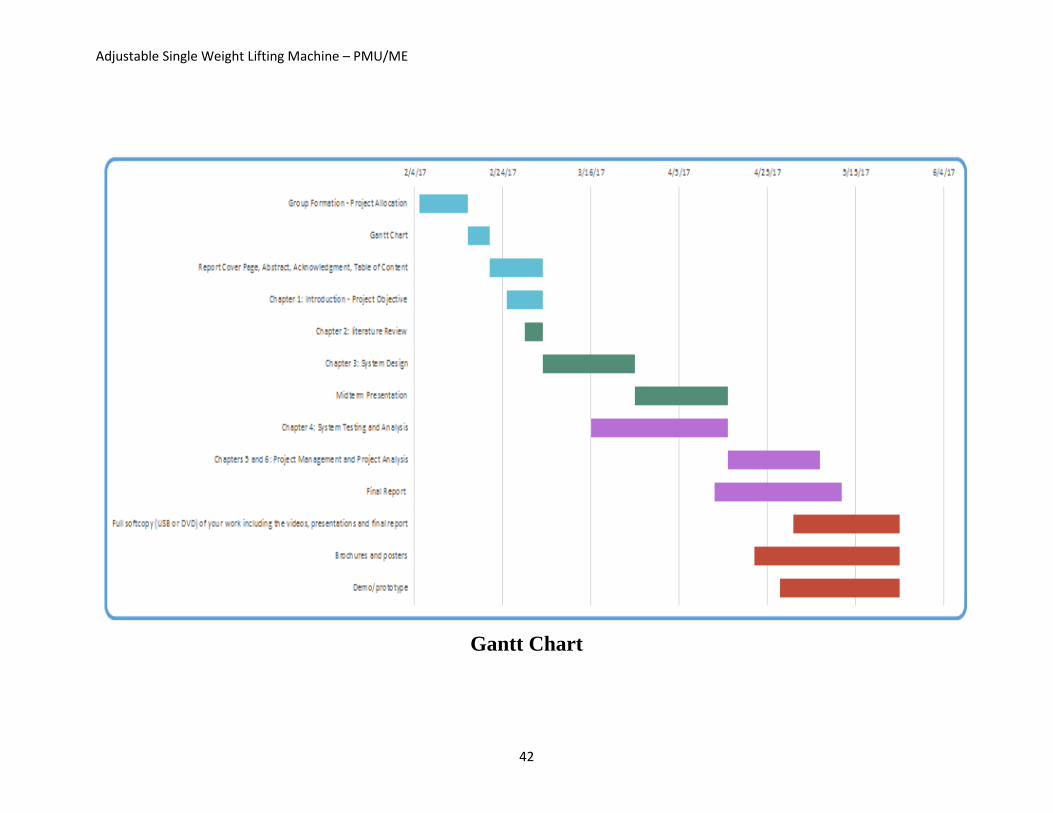
5.1 Project Plan
Table 3 (Project Plan)
Task Team member ETC
Brain storming to Select the project All February, 2017
Take the approval from the advisor AbdulazizAlbaker February, 2017
Sketch the project Mohammed
alZahrani&AbdulazizAlbaker
March, 2017
Search for the materials Mohammed al Quraisha& Abdulla
al fenais
March, 2017
Search for Manufacturer Mohammed al Quraisha& Abdulla
al fenais
April, 2017
Manufacturing the parts AbdulazizAlbaker&Mohammed
alZahrani
April, 2017
Test the project All May, 2017
Transfer the project to campus All May, 2017
Adjustable Single Weight Lifting Machine – PMU/ME
42
Gantt Chart
43
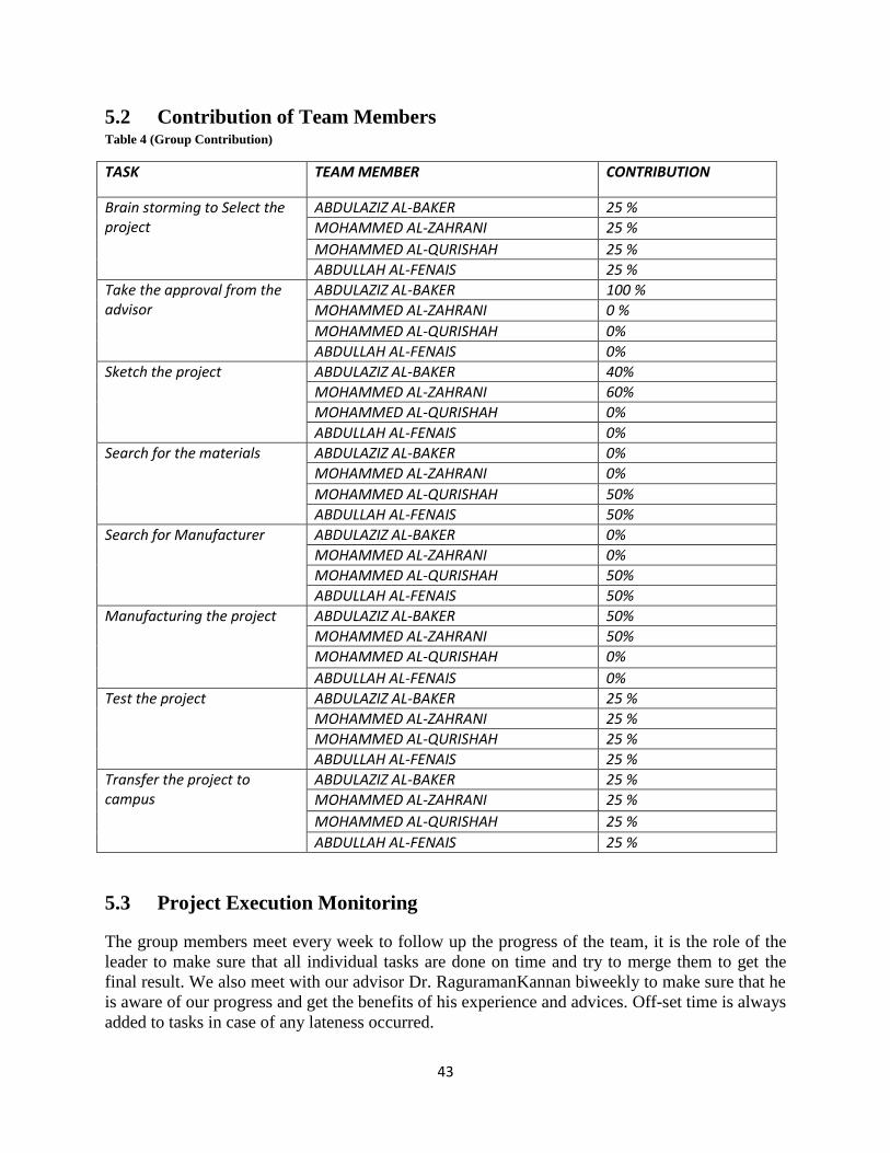
5.2 Contribution of Team Members Table 4 (Group Contribution)
TASK TEAM MEMBER CONTRIBUTION
Brain storming to Select the project
ABDULAZIZ AL-BAKER 25 %
MOHAMMED AL-ZAHRANI 25 %
MOHAMMED AL-QURISHAH 25 %
ABDULLAH AL-FENAIS 25 %
Take the approval from the advisor
ABDULAZIZ AL-BAKER 100 %
MOHAMMED AL-ZAHRANI 0 %
MOHAMMED AL-QURISHAH 0%
ABDULLAH AL-FENAIS 0%
Sketch the project ABDULAZIZ AL-BAKER 40%
MOHAMMED AL-ZAHRANI 60%
MOHAMMED AL-QURISHAH 0%
ABDULLAH AL-FENAIS 0%
Search for the materials ABDULAZIZ AL-BAKER 0%
MOHAMMED AL-ZAHRANI 0%
MOHAMMED AL-QURISHAH 50%
ABDULLAH AL-FENAIS 50%
Search for Manufacturer ABDULAZIZ AL-BAKER 0%
MOHAMMED AL-ZAHRANI 0%
MOHAMMED AL-QURISHAH 50%
ABDULLAH AL-FENAIS 50%
Manufacturing the project ABDULAZIZ AL-BAKER 50%
MOHAMMED AL-ZAHRANI 50%
MOHAMMED AL-QURISHAH 0%
ABDULLAH AL-FENAIS 0%
Test the project ABDULAZIZ AL-BAKER 25 %
MOHAMMED AL-ZAHRANI 25 %
MOHAMMED AL-QURISHAH 25 %
ABDULLAH AL-FENAIS 25 %
Transfer the project to campus
ABDULAZIZ AL-BAKER 25 %
MOHAMMED AL-ZAHRANI 25 %
MOHAMMED AL-QURISHAH 25 %
ABDULLAH AL-FENAIS 25 %
5.3 Project Execution Monitoring The group members meet every week to follow up the progress of the team, it is the role of the
leader to make sure that all individual tasks are done on time and try to merge them to get the
final result. We also meet with our advisor Dr. RaguramanKannan biweekly to make sure that he
is aware of our progress and get the benefits of his experience and advices. Off-set time is always
added to tasks in case of any lateness occurred.

Adjustable Single Weight Lifting Machine – PMU/ME
44
5.4 Challenges and Decision Making Table 5 (Challenges)
Challenges Solving
Finding the proper materials Search at the Dammam industrial city until we
found them
finding a manufacturer Found the aluminum specialized workshop
and dealt with it
Some materials are expensive Search and found the acceptable materials
with good cost
Solidworks ask a help from advisor
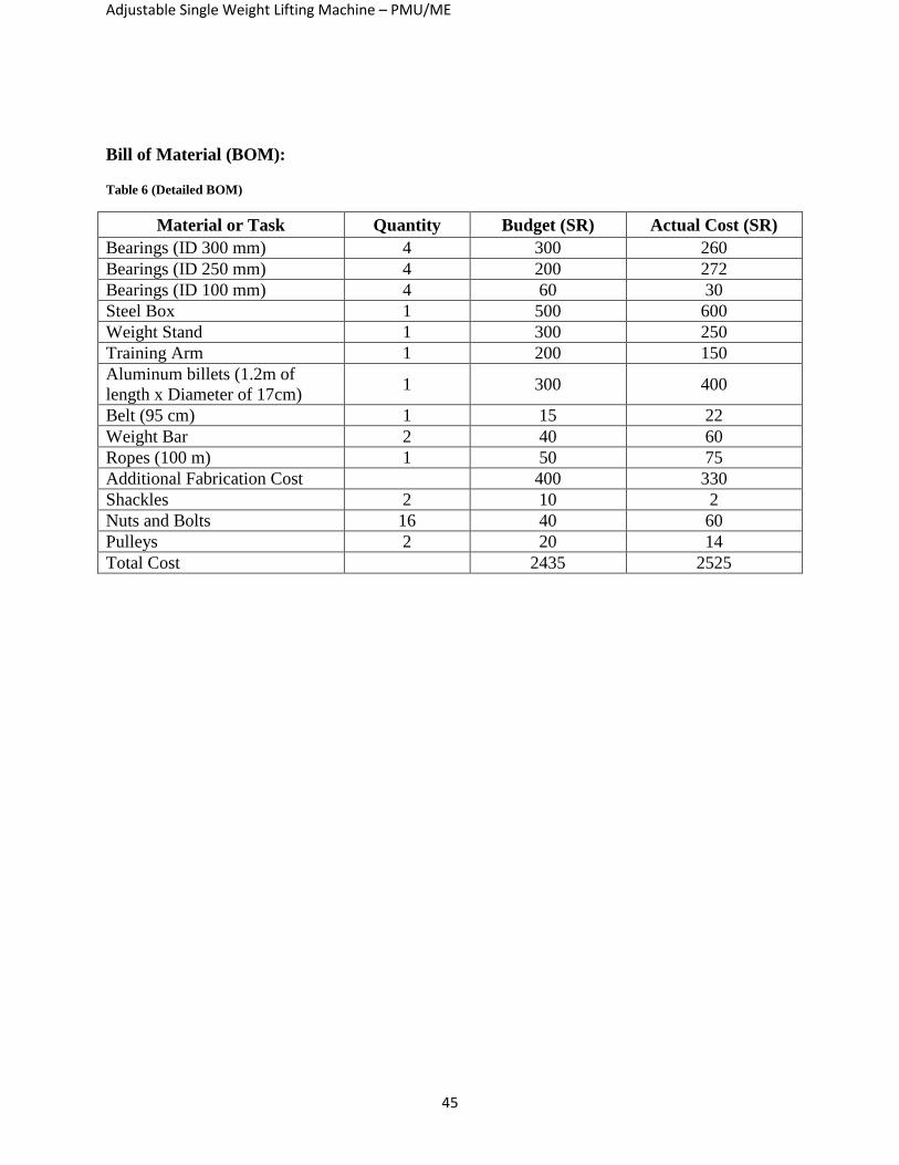
5.5 Project Bill of Materials and Budget
This section explains the distribution of the actual cost for each category. It also shows
the bill of material for each part or task done in our project. It varies between material,
fabrication, and labor cost.
Figure 28 (Actual Cost Analysis)
Adjustable Single Weight Lifting Machine – PMU/ME
45
Bill of Material (BOM):
Table 6 (Detailed BOM)
Material or Task Quantity Budget (SR) Actual Cost (SR)
Bearings (ID 300 mm) 4 300 260
Bearings (ID 250 mm) 4 200 272
Bearings (ID 100 mm) 4 60 30
Steel Box 1 500 600
Weight Stand 1 300 250
Training Arm 1 200 150
Aluminum billets (1.2m of
length x Diameter of 17cm) 1 300 400
Belt (95 cm) 1 15 22
Weight Bar 2 40 60
Ropes (100 m) 1 50 75
Additional Fabrication Cost 400 330
Shackles 2 10 2
Nuts and Bolts 16 40 60
Pulleys 2 20 14
Total Cost 2435 2525
Adjustable Single Weight Lifting Machine – PMU/ME
46
CHAPTER 6
Project Analysis
Adjustable Single Weight Lifting Machine – PMU/ME
47
Chapter 6: Project Analysis
6.1 Lifelong Learning
In this project hardware devices such as my RIO, Arduino, sensors, GSM, Wifi, Bluetooth, etc,,,
is not required. We use in this project one of the best and known software tools (Solidworks
program), actually we took this course before with Dr. Nader but now we improve ourselves in
this program.
For the project management skills and time skills was kind of difficult, but in the end we solve,
for example: when we try to find a time fit all of us during the week days we finally organize our
schedule all over or when we try to find a manufacture for our parts we divide the work between
us so everyone have to search in certain area until we get what we want and we hope to keep up
until the end of the semester.
6.2 Impact of Engineering Solutions
Our project is making a big difference in society, especially to those who buy machine
equipment. Moreover, our project which is a gym machine is doing the same job that other
machines do, but what makes our project better is lightweight comparing to the other machines
and the cost is much cheaper.

Adjustable Single Weight Lifting Machine – PMU/ME
48
Chapter 7: Conclusions and Future Recommendations
7.1 Conclusions
Our project is Adjustable Single Weight Lifting Machine which can be used in any place for
practicing and improving human being health. Our gym machine works basically on different
gear ratio principle. The machine consists of two identical con pulleys that are made from
aluminum, steel box, weight stand, lifting arm, bearings, rubber belt, and ropes. The machine
gives the user the option to change the weight from 5 kg to 80 kg by changing the belt location
which results in different gear ratio starting from 1:4 to 4:1 with using only a 20 kg steel bar. The
project was a great opportunity for us as students to learn and show our capabilities as senior
graduating students. The experience was not easy however we successfully over came all the
obstacles which we faced. There were some challenges regarding the availability of a local
workshop where we can work freely on our project. Another challenge was the cost of building
the prototype is comparatively high for us as students. The availability of the raw material was
also a challenge; it is limited to those who have accounts with the manufactures which hindered
us from buying some raw materials. We learn that even if we have the proper design, and took all
factors in consideration, we need to test the design physically to make sure that the idea is
practical.
7.2 Future Recommendations
- Improving the way of changing the belt location which connects the two aluminum con
pulleys.
- Study on finding better materials which will minimize the total weight of the machine.
Adjustable Single Weight Lifting Machine – PMU/ME
49
References
1) Eisinger, A. (2016, February 15). The Only 7 Gym Machines Worth Using. Retrieved March
05,2017, from http://greatist.com/move/best-gym-machines
2) Verstegen, S. (2014). Prenatal Fitness Modifications For Safety and Comfort. Retrieved
March 05, 2017, from https://www.acefitness.org/blog/5558/prenatal-fitness-modifications-for-
safety-and
3) Doyle, K. (2015, July 15). The History of Exercise Equipment. Retrieved March 05, 2017,
from http://www.livestrong.com/article/274001-the-history-of-exercise-equipment/
4) How Bicycles Work. (2000, April 01). Retrieved March 05, 2017, from
http://adventure.howstuffworks.com/outdoor-activities/biking/bicycle4.htm
5) AZoM, W. B. (2013, June 11). Aluminium - Advantages and Properties of Aluminium.
Retrieved March 05, 2017, from http://www.azom.com/article.aspx?ArticleID=1446
6) Pulley. (2011). Retrieved March 05, 2017, from
http://www.newworldencyclopedia.org/entry/Pulley
50
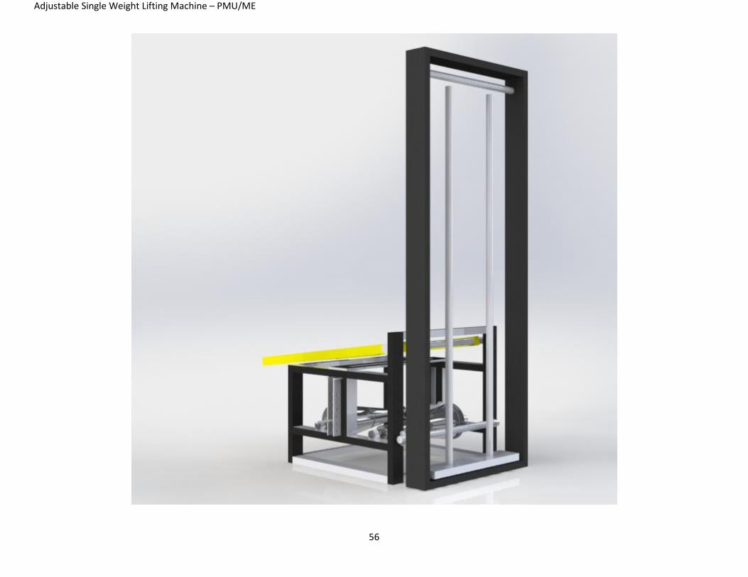
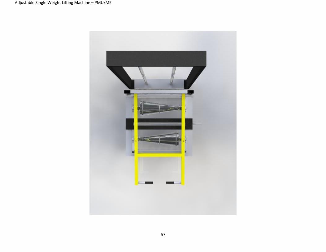
Appendix A: Part Drawings
Adjustable Single Weight Lifting Machine – PMU/ME
51
Adjustable Single Weight Lifting Machine – PMU/ME
52
Adjustable Single Weight Lifting Machine – PMU/ME
53
Adjustable Single Weight Lifting Machine – PMU/ME
54
Adjustable Single Weight Lifting Machine – PMU/ME
55
Adjustable Single Weight Lifting Machine – PMU/ME
56
Adjustable Single Weight Lifting Machine – PMU/ME
57
Adjustable Single Weight Lifting Machine – PMU/ME
58

59