adjustable height and length steel workbench frame 10 ® adjustable height and length steel...
TRANSCRIPT

40724-17041 10SOP-AWB-6
®
Adjustable Height and Length
Steel Workbench Frame
SOP-AWB-6 INSTRUCTIONS
29" - 41" ADJUSTABLE HEIGHT(1" INCREMENTS)
TOOLS REQUIRED
Socket Wrench 7/16" socket
(4) Leveling Feet(52) Carriage Bolt 1/4-20 x 1/2"(52) Split Washer #5/16" (52) Hex Nut 1/4-20
HARDWARE PROVIDED
LENGTH ADJUSTABLE FOR 4', 5', 6' WORK SURFACES
WORK SURFACENOT INCLUDED
USE 4', 5', 6' LONG X 24" WIDE WORK SURFACE ON BENCH FRAME

29" POSITION SHOWN
NOTE: See Step 5 if mounting bench frame to floor, do not use leveling feet.
ADJUSTABLE BENCH FRAME HEIGHT1
NOTE: Do not tighten any fasteners until all the the components are assembled together.
BENCH FRAME LEG ASSEMBLY2
41" POSITION SHOWN
LEVELING FEET
UPPER LEG
CROSS SUPPORT
ADJUSTABLE LEGS
CARRIAGE BOLTS
SPLIT WASHERS HEX NUT
29" - 41" ADJUSTABLE
HEIGHT (1" INCREMENTS)
40724-17042 10SOP-AWB-6

CARRIAGE BOLTS
69.25”57.25”45.25”
40724-17043 10SOP-AWB-6
CARRIAGE BOLTS
HEX NUT SPLIT WASHERS
CROSS BRACES
LEG CONNECTOR
BENCH FRAME ASSEMBLY3
4' Work Surface
NOTE: Do not tighten any fasteners until all the the components are assembled together.
NOTE: Once assembly is complete tighten all fasteners.
5' Work Surface 6' Work Surface
NOTE: ORENTATIONOF LEG CONNECTORS
BENCH FRAME LENGTH ADJUSTMENT LOCATIONS
LENGTH ADJUSTMENTLOCATIONS
LEG ASSEMBLY

®
STACK-ON® PRODUCTS CO.P.O. BOX 489, WAUCONDA, IL 60084
For Customer Service help in the United States call: 1-800-323-9601
ATTACHING WORK SURFACE (NOT INCLUDED) TO BENCH FRAME4
Set work surface on floor upside down. Set bench frame upside down on top of work surface on floor. Use bench frame as a template and pre-drill mounting holes into the work surface.
Attach bench frame to work surface using mounting screws (not included) in pre-drilled holes in bottom of work surface.
NOTE: Mounting screws not included - use correct length screws for your work surface.
WORK SURFACE BENCH FRAME MOUNTING HOLES
USE 4', 5', 6' LONG X 24" WIDE
WORK SURFACE ON BENCH FRAME
40724-17044 10SOP-AWB-6
CARRIAGE BOLTS
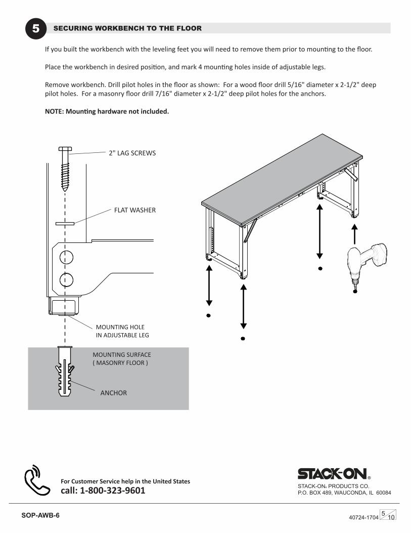
SECURING WORKBENCH TO THE FLOOR5
®
STACK-ON® PRODUCTS CO.P.O. BOX 489, WAUCONDA, IL 60084
For Customer Service help in the United States call: 1-800-323-9601
If you built the workbench with the leveling feet you will need to remove them prior to mounting to the floor.
Place the workbench in desired position, and mark 4 mounting holes inside of adjustable legs.
Remove workbench. Drill pilot holes in the floor as shown: For a wood floor drill 5/16" diameter x 2-1/2" deep pilot holes. For a masonry floor drill 7/16" diameter x 2-1/2" deep pilot holes for the anchors.
NOTE: Mounting hardware not included.
2" LAG SCREWS
FLAT WASHER
ACHORS
MOUNTING SURFACE ( MASONRY FLOOR )
MOUNTING HOLE IN ADJUSTABLE LEG
ANCHOR
40724-17045 10SOP-AWB-6

Socket Wrench 7/16" socket
(4) Leveling Feet(52) Carriage Bolt 1/4-20 x 1/2"(52) Split Washer #5/16" (52) Hex Nut 1/4-20
40724-17046 10SOP-AWB-6
®
Altura y longitude ajustables
Bastidor de acero
SOP-AWB-6 INSTRUCCIONES
29" - 41" LTURA AJUSTABLE (1" INCREMENTOS)
HERRAMIENTAS NECESARIAS
Llave de tubo 7/16" enchufe
(4) Pies Niveladores (52) perno de carro 1/4-20 x 1/2"(52) Arandela dividida #5/16" (52) Tuerca hexagonal 1/4-20
HARDWARE INCLUIDO
LA LONGITUDE ES AJUSTABLE PARA 4', 5', 6' SUPERFICIES DE TRABAJO
LA SUPERFICIE DE TRABAJO NO ESTÁ INCLUIDA USA 4', 5', 6' LARGO X 24" AMPLIO
SUPERFICIE DE TRABAJO EN MARCO DEL BANCO
29" POSICIÓN MOSTRADA
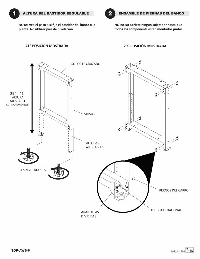
NOTA: Vea el paso 5 si fije el bastidor del banco a la planta. No utilizer pies de nivelación.
ALTURA DEL BASTIDOR REGULABLE1
NOTA: No apriete ningún sujetador hasta que todos los components estén montados juntos.
ENSAMBLE DE PIERNAS DEL BANCO2
41" POSICIÓN MOSTRADA
PIES NIVELADORES
MUSLO
SOPORTE CRUZADO
ALTURAS AJUSTABLES
PERNOS DEL CARRO
ARANDELAS DIVIDIDAS
TUERCA HEXAGONAL
29" - 41" ALTURA
AJUSTABLE (1" INCREMENTOS)
40724-17047 10SOP-AWB-6

69.25”57.25”45.25”
40724-17048 10SOP-AWB-6
PERNOS DEL CARRO
TUERCA HEXAGONAL
ARANDELAS DIVIDIDAS
BRAZOS CRUZADOS
CONECTOR DE PIERNAS
ENSAMBLE DE MARCO DE BANCO 3
4' Superficie de Trabajo
NOTA: No apriete ningún sujetador hasta que todos los componentes estén montados juntos.
NOTA: Una vez completado el montaje, apriete todos los sujetadores.
5' Superficie de Trabajo 6' Superficie de Trabajo
NOTA: ORIENTACIÓN DE CONECTORES DE PIERNAS
LUGARES DE AJUSTE DE LA LONGITUD DEL MARCO DEL BANCO
LUGARES DE AJUSTE DE LONGITUD
ASAMBLEA DE PIERNAS
For Customer Service help in the United States call: 1-800-323-9601
®
STACK-ON® PRODUCTS CO.P.O. BOX 489, WAUCONDA, IL 60084
PARA AYUDA DE SERVICIO AL CLIENTE EN LOS ESTADOS UNIDOS LLAMENOS call: 1-800-323-9601
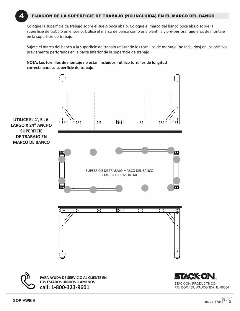
FIJACIÓN DE LA SUPERFICIE DE TRABAJO (NO INCLUIDA) EN EL MARCO DEL BANCO4Coloque la superficie de trabajo sobre el suelo boca abajo. Coloque el marco del banco boca abajo sobre la superficie de trabajo en el suelo. Utilice el marco de banco como una plantilla y pre-perforar agujeros de montaje en la superficie de trabajo.
Sujete el marco del banco a la superficie de trabajo utilizando los tornillos de montaje (no incluidos) en los orificios previamente perforados en la parte inferior de la superficie de trabajo.
NOTA: Los tornillos de montaje no están incluidos - utilice tornillos de longitud correcta para su superficie de trabajo.
SUPERFICIE DE TRABAJO MARCO DEL BANCO ORIFICIOS DE MONTAJE
UTILICE EL 4', 5', 6' LARGO X 24" ANCHO
SUPERFICIE DE TRABAJO EN
MARCO DE BANCO
40724-17049 10SOP-AWB-6
PERNOS DEL CARRO

For Customer Service help in the United States call: 1-800-323-9601
ASEGURANDO EL BANCO DE TRABAJO AL PISO5
®
STACK-ON® PRODUCTS CO.P.O. BOX 489, WAUCONDA, IL 60084
Si ha construido el banco de trabajo con las patas niveladoras, deberá retirarlas antes de montarlas en el piso.
Coloque el banco de trabajo en la posición deseada y marque 4 orificios de montaje dentro de las patas ajustables.
Quite el banco de trabajo. Taladre agujeros piloto en el piso como se muestra: Para un taladro de madera de 5/16 "de diámetro x 2-1 / 2" de profundidad piloto. Agujeros para un orificio de suelo de mampostería de 7/16 "de diámetro x 2-1 / 2" de profundidad para los anclajes.
NOTA: el hardware de montaje no está incluido
2" TORNILLOS DE RETRASO
ARANDELA PLANA
ACHORS
SUPERFICIE DE MONTAJE ( PISO DE ALBAÑIL )
SUJETE DE MONTAGE EN LA PIERNA AJUSTABLE
ANCHOR
40724-17041010SOP-AWB-6
PARA AYUDA DE SERVICIO AL CLIENTE EN LOS ESTADOS UNIDOS LLAMENOS call: 1-800-323-9601