adjust model for 3d printing fileload 3dxpert-exercise-scaling_start.sldprt to solidworks from the...
TRANSCRIPT

Adjust model for 3D Printing
Scaling
13,0600,1489,1604(SP6)
3DXPERT Adjust model for 3D Printing - Scaling 2
In this exercise, we will learn to create Scaling to added 3DP component.
As the printed part cools down, it shrinks.
Therefore, it may be required to scale it up so that it shrinks to the correct size.
To use this command we need to follow few steps (guided):
Load 3DXpert-Exercise-Scaling_Start.SLDPRT to SOLIDWORKS
Launch 3DXpert for SOLIDWORKS.
Add shrinkage compensation.
! Notice/ Remember
Left mouse button name is "pick"
Middle mouse button name is "Exit"
Right mouse button name is "Click"
1. Load 3DXpert-Exercise-Scaling_Start.SLDPRT to SOLIDWORKS from the folder that it was downloaded to.
2. From the Additive Manufacturing tab pick 3XPert for SOLIDWORKS command.
This command will launch 3DXpert for SOLIDWORKS.
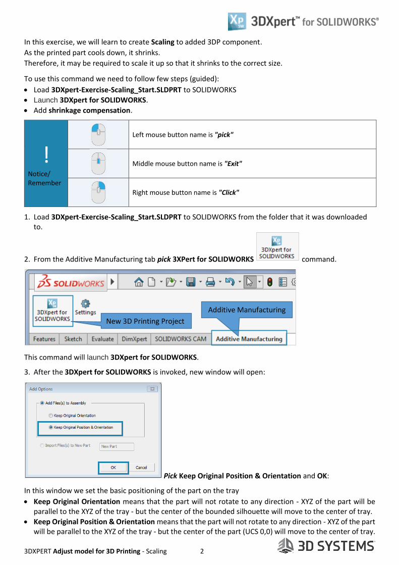
3. After the 3DXpert for SOLIDWORKS is invoked, new window will open:
Pick Keep Original Position & Orientation and OK:
In this window we set the basic positioning of the part on the tray
Keep Original Orientation means that the part will not rotate to any direction - XYZ of the part will be parallel to the XYZ of the tray - but the center of the bounded silhouette will move to the center of tray.
Keep Original Position & Orientation means that the part will not rotate to any direction - XYZ of the part will be parallel to the XYZ of the tray - but the center of the part (UCS 0,0) will move to the center of tray.
New 3D Printing Project
Additive Manufacturing

3DXPERT Adjust model for 3D Printing - Scaling 3
After the file is open the screen will look like this:
Notice the Process Guide on the right side of the screen. This guide contains most of the functionality to enable preparing the part for printing.
4. Save the project, pick the Save command on top left corner.
This command will open the 3DXpert for SOLIDWORKS Explorer. Save the file to the same folder with the downloaded files.
3D Printing Process Guide
3DP Objects Tree
3DP Objects Tab
Assembly Tab Tray
Display Area
Save
3D Printing Project Name
Save
Part on Tray
3D Printing Data

3DXPERT Adjust model for 3D Printing - Scaling 4
After adding the 3DP component the tray will look like this:
From a TOP view
From ISO view
5. Pick shrinkage compensation command from the 3D Printing Process Guide.
shrinkage compensation
1) Pick object 2) Pick a pivot point 3) Set parameters
"Preview" the result without executing
To approve and finish use the "OK"
To approve and continue use the "Apply".
"Cancel" – exit the comand without keep changes

3DXPERT Adjust model for 3D Printing - Scaling 5
Since the command have some defaults its "jumps" to the last stage in this command.
6. Pick the first stage in the Feature Gide - Pick object .
At the first stage it is possible to choose between All Objects (default) and By Pick. The option All Objects does the same shrinkage compensation to all and in case of By Pick we have to repeat the command as needed.
Keep All Objects and Exit (left mouse button) to continue.
7. At the second stage Pick a pivot point is possible to choose between
Center of Selected Geometry (default) and Free Selection to pick any point as a pivot point.
Keep Center of Selected Geometry and Exit (left mouse button) to continue.
8. Last stage Set parameters . Set parameters as shown in the following pictures, to approve and finish use the "OK":
Uniform Show as Factor Non-Uniform Show as Factor
The Uniform parameter is used when the shrinkage compensation is the same to all main
directions (XYZ) and can be changed to Non-Uniform for different values can be used for each main directions (X-Y-Z) separately.
In any method chosen, the Volume Change Rate is displayed.

3DXPERT Adjust model for 3D Printing - Scaling 6
It is possible to show the values as Factor or as Percentage .
Uniform Show as Percentage Non-Uniform Show as Percentage
After shrinkage compensation setting is finished and while the command is active the user can save as Pre-
defined Factor (for a certain material or printing technology for example) and to use it next time.
! Please notice: when using Non-Uniform compensation with different values in any main plan direction ( i.e. XY plane), cylinder in that plane are deformed
End of Exercise.