adeco-rs the design and construction of tunnels using the
TRANSCRIPT

3T&T International ADECO-RS Approach MAY 2000
ADECO-RS
1.0 INTRODUCTIONAnyone who sets out to construct under-ground works, finds himself having totackle and solve a particularly complexcivil engineering problem because, com-pared to surface constructions, it isextremely difficult to determine thebasic design data of underground worksin advance.
First of all it is not a question, as withsurface construction, of graduallyassembling materials (steel, reinforcedconcrete, etc.) with well known strengthand deformation properties to build astructure which finds its future equilib-rium in the desired final configuration,but of acting on a pre-existing equilib-rium and proceeding in some way to a“planned disturbance” of it in conditionsthat are known only approximately.
Another characteristic of under-ground works, well known to design andconstruction engineers, but not alwaysgiven sufficient weight, is that very oftenthe stage at which the structure is subjectto most stress is not the final stage whenthe tunnel is finished and subject toexternal loads predicted at the design
stage, but the intermediate constructionstage, very much more delicate becauseat this stage the effects of the disturbancecaused by excavation have not yet beencompletely confined by the final lining.At this stage the pre-existing stresses inthe rock mass deviated by the opening ofthe cavity are channelled around it(“arch effect”) creating zones ofincreased stress on the walls of the exca-vation.
Just how delicate this intermediatestage is becomes clear if one considersthat it is precisely the correct channellingof stresses around the cavity that deter-mines the integrity and life of a tunnel.Channelling can be produced,depending on size of the stresses in playand the strength and deformation prop-erties of the ground, as follows (fig. 1):
1) close to the profile of the excavation2) far from the profile of the excavation3) not at all
The first case occurs when the groundaround the cavity withstands the devi-ated stress flow around the cavity well,responding elastically in terms ofstrength and deformation.
The second case occurs when theground around the cavity is unable towithstand the deviated stress flow andresponds anelastically, plasticising anddeforming in proportion to the volumeof ground involved in the plasticisationphenomenon; the latter also causes anincrease in the volume of the groundaffected, and propagates radially withthe result that the channelling of thestresses is deviated away from thetunnel into the rock mass until the tri-axial stress state is compatible with thestrength properties of the ground. In thissituation, the “arch effect” is formed farfrom walls of the excavation and theground around it that has been dis-turbed at this point is only able to con-tribute to the final statics with its ownresidual strength and will give rise todeformation of considerable entity.
The third case occurs when theground around the cavity is completelyunable to withstand the deviated stressflow and responds in the failure rangeproducing the collapse of the cavity.
It follows from this analysis of thesethree situations that:
• an arch effect only occurs naturallyin the first case;
• an arch effect is only produced nat-urally in the second case if the ground is“helped” with appropriate interventionto stabilise it;
• in the third case, since an arch effectcannot be produced naturally it must beproduced artificially by operating on itappropriately before it is excavated.
The first and most important task of atunnel design engineer is to determine ifand how an arch effect can be triggeredwhen a tunnel is excavated and then toensure that it is formed by calibratingexcavation and stabilisation operationsappropriately as a function of the partic-ular stress strain conditions.
For this purpose a knowledge of thefollowing is indispensable (fig. 2):
– of the medium in which operationstake place; – of the action taken to excavate; – of the reaction expected followingexcavation. The medium (the ground), which is
the actual construction materialemployed for building tunnels, is anextremely anomalous material whencompared to traditional civil engi-neering construction materials: it is dis-continuous, unhomogeneous andanisotropic. On the surface, it presentsvery varied characteristics which,however, depend exclusively on its ownintrinsic nature (natural consistency),which conditions the morphology of theearth’s crust. At depth, however, itscharacteristics will change as a functionof the stress states it is subject to(acquired consistency), conditioning itsresponse to excavation.
The action occurs when the faceadvances through the medium. It istherefore a distinctly dynamic phenom-enon: the advance of a tunnel may bevisualised as a disk (the face) that pro-ceeds through the rock mass with avelocity V, leaving an empty spacebehind it. It produces a disturbance inthe medium, both in a longitudinal andtransverse direction, which changes theoriginal stress states.
Within the disturbed zone, the orig-inal field of stresses, which can be repre-sented as a network of flow lines, isdeviated by the presence of the excava-
The design and construction of tunnelsusing the approach based on the analysisof controlled deformation in rocks and soilsBy Prof. Eng. Pietro Lunardi, Lunardi Consulting Engineers, Milan
Arch effect
Arch effect
Natural
Diverted
Null
1
2
3
32
1
σ
δFig. 1

tion (fig. 1) and concentrates close to itproducing increased stress. The size ofthis increased stress determines theamplitude of the disturbed zone foreach medium (within which the groundsuffers a loss of geomechanical proper-ties with a consequent increase involume) and therefore the behaviour ofthe cavity in relation to the strength ofthe rock mass σgd.
The size of the disturbed zone close tothe face is defined by the radius of influ-ence of the face Rf, which identifies thearea on which the design engineer mustfocus his attention and within which thepassage from a triaxial to a plane stressstate occurs (the face or transition zone);proper study of a tunnel requires threedimensional methods of calculationand not just two dimensional methods.
The reaction is the deformationresponse of the medium to the action ofexcavation. It is generated ahead of theface, within the area that is disturbedfollowing the general increase in stressin the medium around the cavity anddepends on the medium (consistency)and on the way in which face advance iseffected (action). It may determine theintrusion of material inside the theoret-ical profile of the excavation. Intrusion issynonymous with instability of thetunnel walls.
Three basic situations may arise:If on passing from a triaxial to a plane
stress state during tunnel advance, theprogressive decrease in stress at the face(σ3 = 0) produces stress in the elasticrange ahead of the face, then the wallthat is freed by excavation (the face)remains stable with limited andabsolutely negligible deformation. Inthis case the channelling of stressesaround the cavity (“arch effect”) is pro-duced naturally close to the profile ofthe excavation.
If on the other hand, the progressivedecrease in the stress state at the face(σ3
= 0) produces stress in the elastic-plasticrange in the ground ahead of the face,then the reaction is of importance andthe wall that is freed by excavation, theface, will deform in an elastic-plasticmanner towards the interior of thecavity and give rise to a condition ofshort term stability. This means that inthe absence of intervention, plasticisa-tion is triggered, which by propagatingradially and longitudinally from aroundthe excavation produces a shift of the“arch effect” away from the tunnel intothe rock mass. This movement awayfrom the tunnel can only be controlledby intervening with adequate means ofstabilisation.
If, finally, the progressive decrease inthe stress state at the face (σ3 = 0) pro-duces stress in the failure range in theground ahead of the face, then thedeformation response is unacceptableand a condition of instability exists inthe ground ahead of the face, whichmakes the formation of an “arch effect”impossible: this occurs in non cohesiveor loose ground and an “arch effect”
must be produced in it artificially since itcannot occur naturally.
It follows therefore that the formationof an arch effect and its position withrespect to the cavity (on which we knowthat the long and short term stability of atunnel depends) are signalled by thequality and the size of the “deformationresponse” of the medium to the actionof excavation.
With these considerations as ourstarting point, over twenty five yearsago, we started to study the relation-ships between changes in the stressstate in the medium induced by tunneladvance and the consequent deforma-tion response of the tunnel.
2.0 RESEARCH ON THE DEFORMATIONRESPONSE OF THE MEDIUMThe analysis of the deformationresponse of the rock mass (effect) hasdeveloped during the course ofresearch, both experimental and theo-retical, that began twenty five years agoand is still continuing.
The “first research stage” was dedi-cated above all to systematic study ofthe stress-strain behaviour of a widerange of tunnels during construction.Particular attention was paid to thebehaviour of the face and not just that ofthe cavity as is normally done. The com-plexity of what we were studying, thedeformation response (effect) became
clear very soon and we needed to iden-tify new terms of reference in order todefine it fully (fig. 4):
• the advance core: the volume ofground that lies ahead of the face, virtu-ally cylindrical in shape with the heightand diameter of the cylinder beingapproximately the same size as thediameter of the tunnel;
• extrusion: the primary componentof the deformation response of themedium to the action of excavation thatdevelops largely inside the advancecore; extrusion depends on the strengthand deformation properties of the coreand on the original stress field to whichit was subject; it manifests on the
Underground construction
Medium
Action
Reaction
Sand Clay RockContour ofexcavation
Tunnelface
Convergence
Fig. 2
Advancecore
V
Extrusion
Fall ofground
Fall of ground
Separationof strata
Separation of strata
Collapse of thecavityGround intruded through the
theoretical profile of the tunnel
Failure ofthe face
*We mean for instability the intrusion of material into the tunnelbeyond the theoretical profile of the tunnel
At the face Around the cavityManifestations of instability*
Typologies of deformation1 - Extrusion2 - Preconvergence3 - Convergence
Preconvergence of the cavityConvergence of the cavity
Convergence
PreconvergenceExtrusion
1st research phase
Fig. 3
4
ADECO-RS
T&T International ADECO-RS Approach MAY 2000

5
surface of the face in the direction of thelongitudinal axis of the tunnel and itsgeometry is either more or less axial-symmetric (bellying of the face) or ofgravitational churning (rotation of theface);
• preconvergence of the cavity: con-vergence of the theoretical profile of thetunnel ahead of the face, strictly depen-dent on the relationship between thestrength and deformations properties ofthe advance core and its original stressstate.
Subsequently, during the “secondresearch stage”, detailed analysis -above all in terms of timing - was per-formed on instability phenomena
observed during the construction of atleast 400 km of tunnel in an extremelywide range of ground types and stressstrain conditions. The aim was to seek aconnection between the behaviour ofthe face-advance core system (extrusionand preconvergence) and that of thecavity (convergence).
Once we had established that thedeformation response as a whole (extru-sion, preconvergence and convergence)is systematically conditioned by therigidity of the core of ground at the face(which is therefore the real cause of it),at a third stage, “the third researchstage” we worked to discover to whatextent the deformation response of the
cavity (convergence) could be con-trolled by acting on the rigidity of thatcore. To do this the stress strain behav-iour of the advance core, systematicallycompared to that of the cavity wasanalysed both in the absence and thepresence of intervention to protect andto reinforce the core.
2.1 THE FIRST RESEARCH STAGEThe first research stage (systematicobservation of the deformation behav-iour of the face-advance core system)was conducted by using instrumentsand visual observation to monitor thestability and deformation behaviour ofthe advance core and walls of tunnels,
paying particular attention to the fol-lowing phenomena (fig. 3):
a) extrusion of the face;b) preconvergence of the cavity;c) convergence of the cavity (decrease
in the size of the theoretical crosssection of the excavation after thepassage of the face).
Systematic visual observation per-formed inside cavities enabled the fol-lowing manifestations of instabilitylocated on the face or around it (insta-bility is intended as occurring whenevermaterial intrudes into an excavationbeyond the theoretical profile) to beassociated with the types of deforma-tion mentioned above:
a) fall of ground, spalling and failure ofthe face located at the face-advance coresystem and following extrusion of theface and preconvergence;
b) fall of ground, spalling and collapseof the cavity located on the roof andwalls of the cavity and following conver-gence of the cavity itself.
2.2 THE SECOND RESEARCH STAGEOnce the types of deformation andmanifestations of instability that occuron the core at the face and on the roofand walls of a tunnel had been identi-fied, we asked ourselves whether obser-vation of the former might in some waygive us an indication of what the typeand size of the latter would be. Thesecond stage of research thus com-menced [to seek possible connectionsbetween the deformation of the face-advance core system (extrusion andpreconvergence) and that of the cavity(convergence)]. It was performed bystudying, observing and monitoringdeformation at the face and in thecavity, with particular attention paid tothe magnitude and chronologicalsequence in relation to systems, stagesand paces of construction employed inthe various tunnels.
It is important here to briefly illustratethe observations made, with a few sig-nificant examples before examining theresults of this experimental stage.
2.2.1 THE EXAMPLE OF THE FREJUSMOTORWAY TUNNEL (1975) Ninety five percent of the route of theFrejus motorway tunnel (13 km inlength with overburdens of up to 1,700m.) passes through a metamorphousformation of schistose crystalline lime-stone, that is lithologically homoge-neous for the length of the route.
The design of the tunnel was made onthe basis of a geological and geome-chanical survey conducted from theadjacent railway tunnel (completed in1860) and from the service tunnels. Thestrength and deformation tests per-formed on samples of the schistose crys-talline limestone gave the followingaverage geotechnical values:
– angle of friction: 35°; – cohesion: 30 Kg/cm2 (= 3 MPa);– elastic modulus: 100,000 Kg/cm2 (=10,000 MPa).
V=200 m/month
V=200 m/month
V=100 m/month
V=100 m/month
Convergence withtunnel face stationary
785
43
21
90 (days)60300
650
600
550
500
450
400
350
300
250
200
150
100
50
0
(mm)
90 (days)60300
650
600
550
500
450
400
350
300
250
200
150
100
50
0
(mm)
No.6 monitoring stationoverburden H=1200m
Fig. 4
No.6 monitoring stationoverburden H=1200m
7859
4
12
3
6
V
V
DA
Measures of convergence
The Motorway Frejus Tunnel
Ventilating shaft Ventilating shaft
Frejus peak 2097m
11 10 9 8 7 6 5 4 3 2 1 0km
3500
2500
1500
France Italy
d=3000md=2400m
d=1800md=1200m
d=600m
Outlines at 'd' distancefrom the tunnel centre-line
Moraine
5 6 7
(m)
Monitoringstations
Monitoring station
Chainage (m)
Overburden (m) 11
1 2 3 4 5 6 7 8 9
845
490
861
500
2772
580
3954
590
4507
740
5172
1200
5533
1400
5915
1530
6066
1640
T&T International ADECO-RS Approach MAY 2000

T&T International ADECO-RS Approach MAY 20006
ADECO-RS
No forecasts of deformation behav-iour were made in the original designfor the tunnel (1975), since this was notpart of standard practice at that time.
Account was taken of Sommeiller’sexperience during the construction ofthe adjacent railway tunnel about acentury before. Full face advance wasdecided with immediate stabilisation ofthe ring of rock around the cavity withend-anchored active roof bolts to adepth of 4.5 m. supplemented withshotcrete. The final lining was in con-crete with an average thickness of 70 cm.cast afterwards to complete the tunnel.
Study of deformation behaviour con-stituted the most significant part of thecampaign of observations and measure-ments performed during construction.The purpose was to monitor theresponse of the rock mass to the stabili-sation measures under the exceptionalcircumstance of driving a tunnel for thefirst time though a homogeneous rockmass (crystalline limestone) with vari-able overburdens subject to a stress fieldwhich increased and varied as a func-tion of the overburden (0 - 1,700 m.).
Up to an overburden of 500 m., therock mass remained stressed within theelastic range with the tunnel mani-festing stable face behaviour, negligibledeformation and limited instability atthe face and in the cavity, consistingexclusively of fall of ground.
As the overburden and consequentlythe stress state increased, the rock massentered the elastic-plastic range andtunnel behaviour became face stable inthe short term, with convergence of thecavity measurable in decimetres (dia-metrical convergence 10 - 20 cm.). Theband of reinforced rock contributedeffectively towards the statics of thetunnel, limiting the amount of conver-gence and preventing further manifes-tations of instability.
The good quality of the rock alsohelped to maintain advance rates at 200m. per month until work halted tem-porarily at metre 5,173 for the Summerholiday break, in a zone of homoge-neous rock with an overburden of
approximately 1,200 m.Convergence measurement station
No. 6 installed immediately 1 meterback from the face (metre 5,172)showed maximum deformation ofapproximately 10 cm, after 10 days ofzero tunnel advance (fig. 4). It wasundoubtedly creep deformation (witha constant load) only, since the facehad remained at a complete haltduring that time. When advancerecommenced, diametric conver-gence for that cross section increasedvery brusquely to values never beforeencountered reaching 60 cm. after 3months, while further ahead itreturned to normal values (diamet-rical convergence of 20 cm.) after 20 or30 metres as advanced resumed.
It must be pointed out that beforework halted the tunnel had been rein-forced up to one metre from the facewith more than 30 radial roof bolts perlinear metre of tunnel, but no ground
improvement had been performed onthe core at the face.
Once advance resumed, stabilisationprocedures around the cavity continuedwith the same intensity and the samework rhythms as before.
The conclusion drawn was that whiletunnel advance was halted, the core ofground at the face, not being assisted byany reinforcement intervention, hadhad time to extrude into the elastic-plastic range and this had triggered aphenomenon of relaxation of stress,through creep, of the rock mass aroundit (preconvergence). This had in turncaused the considerable increase inconvergence of the cavity with respectto normal values.
2.2.2 THE EXAMPLE OF THE “SANTOSTEFANO” TUNNEL (1984)The “Santo Stefano” tunnel is on thenew twin track Genoa to Ventimigliarailway line located on the sectionbetween S. Lorenzo al Mare andOspedaletti.
It runs through a Helminthoid flyschformation characteristic of westernLiguria. It consists of clayey and clayey-arenaceous schists with thin banks offolded and intensely fractured sand-stones and marly limestones. The clayschist component is heavily laminated.An extremely tectonised transition zonemarks the passage between the H1 zoneand the more marly-limestone-like H2zone .
Strength tests carried out in the labo-ratory on samples gave angle of frictionvalues varying between 20° and 24° andcohesion from 15 Kg/cm2 (= 1.5 MPa) to0.
In this case too, with work beginningin 1982, no forecasts of tunnel defor-mation behaviour were made.
The original design involved full face
advance with steel ribs and shotcretefor the primary lining and a thick ring ofconcrete (up to 110 cm.) for the finallining.
During excavation it was found thatas long as the ground remained elastic,deformation at the face and in thetunnel was negligible and there werepractically no manifestations oflocalised instability (stable face behav-iour). When the tunnel entered a zoneaffected by residual stress states of tec-tonic origin, where the stress state wasin the elastic-plastic field, deformationphenomena began to cause some diffi-culty, also due to the appearance ofsizeable asymmetrical thrusts causedby rigid masses dispersed in the plasticmatrix. As this occurred, layers of mate-rial were seen to break off at the face, asure sign of the presence of extrusion-type movement typical of a face stablein the short term situation; convergencereached decimetric values.
At a certain moment the stress stateof the rock mass had obviously devel-oped into the failure range and theentire face failed (unstable face situa-tion), followed within a few hours bythe collapse of the cavity with diametricconvergence of over 2 m. also for a con-siderable stretch of more than 30 m. oftunnel behind the face, even in the partwhere ribs and shotcrete had beenplaced (photo 1).
It should be noted at this point, thatthe type of ground encountered in thethree stress-strain situations mentionedwas essentially the same and that thephenomenon of tunnel collapse withconvergence measurable in metres,even in a part of the tunnel where theprimary lining had already been placed,only occurred when the core at the facewas no longer rigid and able to con-tribute to the statics of the tunnel.
Photo 1: S. Stefano Tunnel (Italy, Genoa To Ventimiglia Rail Line, ground:tectonised and laminated marly-limestone flysch, overburden: 150 m, tunneldiameter: 12 m.). Collapse of the cavity.
Synthesis of the second research phase
The strain behaviour of the face-advance core system conditions the strain behaviour of the cavity
Fall of ground Fall of ground
Extrusion
Failure of the face Collapse ofthe cavity
Preconvergence andconvergence
Ground intruded through the theoretical profile of the tunnelPreconvergence of the cavityConvergence of the cavity
Fig. 5
2nd research phase

7
2.2.3 THE EXAMPLE OF THE “TASSO”TUNNEL (1988)The “Tasso” tunnel is one of a series oftunnels excavated towards the end ofthe 1980’s for the new “High Speed”Rome to Florence railway line. Thearea in which the tunnel is located liesin the lake basin of the ValdarnoSuperiore and consists of silty sandsand sandy silts with interbedding oflevels of silty clays containing sandylentils and levels saturated with water.
The original design involved halfface advance, stabilising the walls withribs and shotcrete. The ribs wereanchored at the feet with sub-hori-zontal tie bars and given a foundationof micropiles or columns of groundimproved by jet-grouting.
Initially excavation proceededunder face stable in the short termconditions with no appreciable defor-mation phenomena either at the faceor in the tunnel.
As the overburden increased, andtherefore also the stress state of themedium, and given also the poor geo-mechanical characteristics of theground, conditions of face stable inthe short term rapidly changed tothose of an unstable face. Followingthe failure of the face despite half-faceadvance, approximately 30-40 m. oftunnel already excavated and pro-tected with ribs and shotcrete also col-lapsed during the course of one single
night with convergence in the order of3-4 m. (fig. 26)
2.2.4 RESULTS OF THE SECONDRESEARCH STAGEStudy and analysis of the cases illus-trated and other similar cases, whichwould take too long to describe here,produced many ideas of great interest.The following points appeared clearlyfrom the Frejus study:
• when advancing through ground inelastic-plastic conditions it is very impor-tant to maintained constant and sus-tained excavation cycles in order to avoidgiving the core time to deform: it is thuspossible to prevent the triggering of extru-sion and preconvergence phenomenawhich constitute the starting point of sub-sequent convergence of the cavity.
On the other hand it emerged fromthe other experiences cited and othercases that:
• the failure of the core and the col-lapse of the cavity never occur withoutone being followed by the other and inparticular without the latter being pre-ceded by the former.
The following was clear from thesecond research stage (fig. 5):
1) there is a close connection betweenextrusion of the core at the face and thephenomena of preconvergence andconvergence of the cavity;
2) there are close connectionsbetween the failure of the advance coreand the collapse of the cavity even if thelatter has been stabilised;
3) deformation phenomena in thecavity are always chronologically con-sequent to and dependent on those thatinvolve the core of ground at the face.
It also became clear that it was neces-sary for the formation of an arch effect,which as we know conditions the sta-bility of a tunnel, to have already beentriggered ahead of the face to be able tocontinue to function in a determinedcross section after the face has alreadypassed ahead of it.
2.3 THE THIRD RESEARCH STAGEThe results of the second research stagereinforced the impression, which wealready had that the deformation of theadvance core of a tunnel was the truecause of the whole deformation processin all its components (extrusion, precon-vergence and convergence) and that as aconsequence, the rigidity of the coreplayed a determining role in the stabilityof a tunnel both in the long and short
term.If one takes a point A located on the
profile of the crown of a tunnel still to beexcavated, it is in fact quite clear that itsradial movement u (preconvergence) asthe face approaches it depends on thestrength and deformation properties ofthe ground inside the profile of the futuretunnel.
If the course of its radial movement isplotted on a graph p-u (where p is theconfinement pressure exerted radially onA) it can be seen (fig. 6) that as long as theface is still distant (distance from Agreater than the radius of influence of theface Rf) the stress condition of A remainsunchanged (radial confinement pressurep0 = original pressure). As the faceapproaches, however, the radial confine-ment pressure p also diminishes as aresult: A will then start to move radiallytowards the inside of the future cavity.How far it moves depends, as we havesaid and as is quite obvious, on thestresses present and on the deformationproperties of the core which determinesits equilibrium and not only on the geo-mechanical characteristics of the sur-rounding ground.
After the passage of the face, on theother hand, the radial movement of A willcontinue, in the elastic or elastic-plasticrange, as a function of the pre-existingstress states, of the characteristics of theground behind the lining and of theradial confinement pressure exerted bystabilisation works (preliminary lining,final lining) on which the equilibrium ofpoint A depends.
The qualitative graph in fig. 6 shows,other conditions remaining unchanged,the course of the deformation to which Ais subject in the case of a deformableadvance core (curve I) and in the case ofa rigid advance core (curve II): obviously,up to the passage of the face, the radialdeformation of point A as the radial con-finement pressure p reduces is less for arigid core than for a deformable core. Itwould also appear probable that evenafter the passage of the face, and there-
Actions of confinement and preconfinement of the cavity
Preconfinementaction
Confinementaction
Fig. 7
Eg
P0
p1
u1
u2
Ec
Ec
Ec
p2=0
Rf
Eg
Eg
V
V
V
A
A
A
0
1
2
The radial displacement of point a dependson the rigidityof the advance core
u1II u1
I<
u2II
II
u1II
u2I
I
u1I
u2II u2
I<
I = no reinforcement (Ec = Eg)
II = reinforcement of the core (Ec > Eg)
Ec = modulus of elasticity of the core
Eg = modulus of elasticity of the ground
u
p2 = 0 p1 p0 p
Fig. 6
T&T International ADECO-RS Approach MAY 2000

8
ADECO-RS
fore without the confinement exerted bythe advance core, the curves I and IIwould remain clearly separate and thatthe movement of point A would bedetermined by its previous stress-strainhistory. It follows that the deformationproperties of the advance core consti-tute a factor capable of conditioning thedeformation response of the ground toexcavation and it must be consideredthe true cause of it.
Now, if the deformation properties ofthe advance core constitute the truecause of the deformation response ofthe ground to excavation, it seemslogical to hypothesise making use of thecore as a new tool for controlling thatresponse, by acting on its rigidity withappropriate intervention.
We therefore worked on the possi-bility of regulating the rigidity of theadvance core in order to ascertain towhat extent this would make it possibleto control the deformation response ofthe cavity.
To do this, new technologies and newtypes of intervention had to beresearched and developed that wouldact on the core protecting it from toomuch stress (protective techniques)and/or conserving or improving itsstrength and deformation properties(reinforcement techniques). These par-ticular types of intervention are termed“conservation techniques” or alterna-tively “cavity preconfinement tech-niques” to distinguish them fromordinary confinement which only actson the ground surrounding the cavityafter the passage of the face (fig. 7) [1].
The new ideas were then tried out onthe construction of a few tunnels undervery difficult stress-strain conditions.One such experiment on a particularlydifficult tunnel and therefore also verysignificant is described below.
2.3.1 THE “VASTO” TUNNELThe route of the tunnel, part of the newAncona to Bari railway line, runs forapproximately 6,200 metres under thehills on which the village of Vasto lies.
From a geological viewpoint (fig. 8),the bottom and middle part of this hillyrelief consists of a complex of groundsmainly of a silty, clayey constitution,grey in colour, stratified with thin sandy
intercalations, while the top part con-sists of a bank of conglomerates,cemented to a varying extent, overwhich a layer of sandy-silty groundextends, yellowish brown in colour.
The tunnel runs entirely through thebase clay formation with the exceptionof the initial sections near the portals. Atthe depth of the tunnel the ground issaturated with water and extremely sen-sitive to dislocation.
2.3.1.1 A BRIEF HISTORY OF THEEXCAVATIONThe works began in 1984 at the Northportal and continued slowly betweenrepeated and serious incidents untilApril 1990.
The original design involved half faceexcavation, immediately protected witha temporary lining of shotcrete, steelribs and welded steel mesh reinforce-ment. The final lining in reinforced con-crete, one metre thick was cast straightbehind the face and still in the presenceof the core. The side walls of the tunnelwere cast subsequently for underpin-
ning and the casting of the tunnel invertcompleted the work.
After the first serious incident oftunnel deformation, an attempt wasmade to resume tunnel advanceemploying several methods , which all,however proved to be completely inad-equate and finally a disastrous cave-inoccurred at chainage Km. 38+075 underan overburden of 38 m., which involvedthe face (photo 2) and then a section ofapproximately 40 m. behind it. It pro-duced deformation of enormous size(greater than one meter) in the finallining and it was impossible to continueworking.
At this point I was called in to find asolution that would allow the haltedworks to resume and to complete thetunnel. I tackled the far from simpleproblem by employing a new advancemethod for the rest of the tunnel whichwas based on principles of controllingdeformation by stiffening the core at theface, and then by preconfinement tech-niques.
2.3.1.2 THE SURVEY PHASE FOR THE“VASTO” TUNNELBefore commencing a new design, itwas felt wise to acquire a more detailedgeotechnical knowledge of the materialto be excavated.
The ground, belonging to the bottomclay formation, was classified as clayeysilts or silty clays from medium to highlyplastic and impermeable, markedly sus-ceptible to swelling when soaked inwater.
Though direct shear tests in a triaxialcell provided rather a wide range ofvalues for cohesion and angle of friction,they did give very low average values forstrength.
Some “triaxial cell extrusion tests”
were then used to model tunneladvance in the laboratory under theactual stress conditions of the tunnel insitu. These, integrated with simple finiteelement mathematical models made itpossible to calibrate the geomechanicalparameters (c, Ø, E) for use in the sub-sequent diagnosis and therapy phases.Direct simulation of the triaxial cellextrusion tests available (integrated withboth consolidated and non consoli-dated triaxial cell shear tests) were usedto determine the following ranges ofvariation for the main geomechanicalparameters:
cu = undrained cohesion = 0.15 - 0.4Mpa (= 1.5 - 4 Kg/cm2)c’ = drained cohesion = 0 - 0.2 MPa(= 0 - 2 Kg/cm2)Øu= undrained angle of friction = 0°- 10°Ø’ = drained angle of friction = 18° - 24°E = Young’s elastic modulus = 500 -5,000 Mpa (= 5,000 - 50,000 Kg/cm2).
2.3.1.3 DIAGNOSIS PHASE FOR THE“VASTO” TUNNELThe input for this phase was the geolog-ical, geotechnical, geomechanical andhydrogeological knowledge obtainedusing theoretical and experimentalmethods on the data from in situsurveys and laboratory tests performedon the ground in question. It was usedto make forecasts of the stress-strainbehaviour of the face and the cavity inthe absence of intervention to stabilisethe tunnel. The purpose was to dividethe tunnel into sections, each withuniform deformation behaviour interms of the three basic stress-strainconditions that may occur .
The diagnosis study then continuedwith an analysis of the shear mecha-nisms and instability kinematics thatwould be produced following the devel-
Photo 2: Vasto Tunnel (Italy, Ancona to Bari Rail Line, ground: silty clay,overburden: 135 m, tunnel diameter: 12.20 m.). The extrusion of the ground throughthe face during heading and bench excavation (according to NATM principles).
T&T International ADECO-RS Approach MAY 2000
200
100
0
(m)
Ancona Bari
0km 0.5km 1km 2km 3km
1.00
0.80
0.60
0.40
0.20
0
4km 5km
Lot 1 Lot 2
North South
0 0.20 0.40 0.60 0.80 1.00 1.20 1.40(Mpa)
(Mp
a)
Sand andgravel
Calcareousconglomerate
Silty sandand sandy silt
Clayey siltand silty clay
Silty clay Clay
Ancona to Bari railway line - 'Vasto' tunnel
cu
c'
= 21.7 KN/m3
c' = 0.02 MPa
cu = 0.15 MPa= 24˚'
'
Milan Venice
BolognaAnconaPescara
BariNaples
CosenzaMessina
Palermo
Cagliari
Vasto
Florence
Turin
Fig. 8
Survey phase

9T&T International ADECO-RS Approach MAY 2000
opment of deformation phenomenaand concluded with an estimate of theextension of the unstable zones and thesize of the loads mobilised which,however, do not fall within the scope ofthis article.
2.3.1.4 FORECASTING STRESS-STRAINBEHAVIOURForecasts of the stress-strain behaviouralong the route were made using twodifferent procedures (fig. 28), both validfor low, medium and high stress states:the first, more immediate, is based oncharacteristic line theory (calculatedusing analytical or numerical methodsaccording to the situation), the other,rather lengthier, is based on triaxial cellextrusion tests, mentioned in the para-graph on the survey phase.
In the case of the “Vasto” tunnel, apartfrom short sections near the portals, bothprocedures forecast unstable face behav-iour with considerable extrusion and, asa consequence, also preconvergence andconvergence (over 100 cm. radially).These values are such as to produceserious manifestations of instability, suchas the failure of the face and, as a conse-quence, the collapse of the cavity.
2.3.1.5 THE THERAPY PHASE FOR THE“VASTO” TUNNELThe forecasts produced in the diagnosisphase were used as a basis for decidingon the type of action to exert (precon-
finement or simple confinement) andon the intervention required, in thecontext of the behaviour category thatwas forecast, to achieve complete stabil-isation of the tunnel.
First, consideration was given to thecharacteristics of the ground to be tun-nelled (including the Southern portal tobe opened under land slip conditions)and the results of the diagnosis phasewhich forecast face unstable behaviourfor the whole length of the undergroundroute (stress in the failure range, zeroarch effect, typical manifestations ofinstability: collapse of the face, failure ofthe cavity). It was then decided to sta-bilise the tunnel by exerting preconfine-ment action, intervening decidedlyahead of the face to guarantee the for-mation of an artificial arch effect, again,ahead of the face.
Translated into more detail, it wasdecided to employ full face advanceafter first adopting mixed conservationtechniques to create a preconfinementeffect by acting both around the core(protective action) and on it directly(reinforcement action).
Three alternative tunnel section types(fig. 9) were then designed to be adoptedaccording to the homogeneity and con-sistency of the ground encounteredduring tunnel advance.
The only difference between thethree types was the type of treatment(preconfinement or prereinforcement)
P.F.P.S.
P.F.P.F.
Fig. 9
Ancona to Bari railway line - 'Vasto' tunnel
Solution by means of jet-grouting
Solution by means of FGT + FGT
Solution by means of mechanical precutting + FGT
FGT = Fibre glass tubes
Silty sands andsandy silts
Clayey silts andsilty clays
Clays
Therapy phase

10
ADECO-RS
to be employed ahead of the facearound the future cavity, while themethod of ground reinforcementemployed in the advance core was thesame for all three.
The choice of technique to beemployed around the core was strictlydependent on the nature and theacquired consistency of the ground tobe tunnelled.
In granular ground or where cohe-sion was poor, characterised by weakshear strength, horizontal jet-groutingwas specified.
The most appropriate technology tocreate strong shells ahead of the face incohesive, compact and homogeneousground, able to guarantee the mobilisa-tion of an “arch effect”, is, as is now wellknown, that of mechanical precutting.
In grounds where the values forundrained shear strength and cohesionmake the use of this technology inad-visable a band of improved groundahead of the face around the core andthe cavity can be obtained usingclaquage injections performed usingspecially fitted fibre glass tubes.
All three tunnel section types werecompleted with a preliminary confine-ment action down from the face con-sisting of steel ribs and shotcrete, closedwith the tunnel invert and then after-wards, the placing of the final lining inconcrete.
Once the tunnel section type hadbeen decided, design of the reinforce-ment of the advance core using fibreglass tubes was performed. This con-sisted of deciding the number of tubesto be inserted, their length and thegeometry of their configuration on theface.
As with the approach adopted in thediagnosis phase to forecast cavitybehaviour, two different procedures
were adopted to decide on the numberof the fibre glass tubes (fig. 10).
The first procedure was based on thecharacteristic line method, taking intoaccount, in a simplified manner, theeffect of reinforcing the advance corewhen calculating the correspondingcharacteristic line.
The second procedure for the designof ground reinforcement of the advancecore was based on interpretation of theextrusion curves obtained from triaxialextrusion tests. Having first identifiedthe minimum confinement pressurecurve Pi required to stabilise the face(defined as the borderline pressurebetween the “elastic” and the “elastic-plastic” arm of the extrusion curve),experimental diagrams of the typeshown in the same figure were used tocalculate the number of tubes requiredto guarantee the safety of the face withthe desired safety coefficient.
Both approaches (extrusion tests andcharacteristic lines) furnished compa-rable results, in confirmation of theconceptual analogy that they have incommon.
2.3.1.6 THE OPERATIONAL PHASE FOR THE“VASTO” TUNNELIn 1992 work resumed almost simulta-neously on both portals, at the Northportal to repair the collapsed sectionof tunnel and at the South portal tobegin tunnel advance. Averageadvance rates, working 7 days perweek were approximately 50 m. permonth of finished tunnel (photo 3).
Figure 11 compares charts foraverage monthly advance rates graphswith those for convergence measuredduring the same period. The distincttendency of the latter to follow theformer in inverse proportion is particu-larly significant and confirms the fact
that the less time that the core has inwhich to deform, the less extrusion andpreconvergence is triggered. Since con-vergence depends on the extrusion andpreconvergence; it is more limited as aconsequence.
2.3.1.7 THE MONITORING PHASE DURINGCONSTRUCTION FOR THE “VASTO” TUNNELThe monitoring phase began at thesame time as excavation and involvedinterpreting the deformation responseof the medium to excavation for thepurpose of optimising and calibratingthe various techniques employed to sta-bilise the tunnel.
In addition to the normal measure-ments of convergence and pressure,systematic and simultaneous measure-ments were also taken of extrusion andconvergence for the “Vasto” tunnel.These constituted a novelty of particularinterest, especially considering theresults that they have furnished to date.
The results of these measurementsare summarised in the graphs given infig. 12 that show the simultaneouscourse of extrusion and convergence for
a complete work cycle.Examination of the graphs shows that
as the face advances and as the depth ofthe reinforced part of the advance corereduces from an initial 15 m. to only 5 m.(with a consequent reduction in itsaverage rigidity) a deformation responseof the face itself (extrusion) and of thecavity down from the face (conver-gence) develops and this graduallymoves from the elastic range towardsthe elastic-plastic range. The conver-gence curves in particular start with aninitial tendency typical of a situationwhich moves rapidly towards stability(maximum values of the order of 10 cm.,which are produced followingmaximum values for extrusion of lessthan 2.5 cm.) and then gradually changecourse in a direction indicating anincreasing probability of deformationbeing unable to stop. For example,when the length of the reinforced corefalls below 5 m. extrusion of the order of10 cm develops which gives rise to con-vergence four times greater than thatmeasured at the beginning of the workcycle.
In this context, then, combinedreading of extrusion and convergenceof the cavity is an extremely importantindicator for the design engineer to beable to establish the moment at whichadvance must halt to carry out anothercycle of reinforcement and restore theminimum depth of reinforced corerequired to maintain the ground, if notin the elastic range at least away fromthe failure range.
2.3.2 RESULTS OF THE THIRD RESEARCH STAGEThe study and experimentation per-formed on the Vasto tunnel clearlyshowed both the existence of a closeconnection between deformation thatoccurs in the advance core of a tunnel(extrusion) and that which developssubsequently around the cavity after thepassage of the face (convergence) andalso (fig. 13, results of the third researchstage), that deformation of the cavity
Photo 3: Vasto Tunnel: reinforcing ofthe advance core with fibre-glass tubesduring full face excavation (accordingto A.DE.CO.-RS principles).
140
120
100
80
60
40
20
0
Face
Cavity
0 45 90 135 180 225 270 315 Rc = f(C*,ϕ) = resistance ofthe half core after reinforcementP(t/m2)
Pi(t/m2)
Pi(t/m2)
Rc
Rc
P
n
Rc
R(t/m2)
c Kp
0 0.2 0.4 0.6 0.8 10.90.70.50.30.1
Experimental curves todetermine the number offibreglass tubes on the basisof the increase in shearstrength
No. tubes/m2
No. tubes/m2
U(cm)
Fig. 10
Therapy phase Evaluation of the core reinforcement intensityneeded to prevent core instability
Using the characteristic line method
Using the extrusion tests
P
σv= 75 t/m2
σv= 86 t/m2
σv= 75 t/m2
σv= 65 t/m2
σv γ~_ H
Pi
Ex
d
0.070
0.060
0.050
0.040
0.030
0.020
0.010
0.0000 20 40 50 70 903010 60 80 100110120 0 0.1 0.2 0.3 0.4 0.5 0.6 0.7 0.8 0.9 1P = limit pressure of
confinement of the extrustion
Ex/d
20
16
12
08
04
00
n
Experimental curves todetermine the number offibreglass tubes on the basisof the pull-out test
N limFs
T&T International ADECO-RS Approach MAY 2000

11T&T International ADECO-RS Approach MAY 2000
can be controlled and considerablyreduced by artificially regulating thedeformation properties, and thereforethe rigidity, of the advance core (con-finement of extrusion). This is possibleby employing appropriate stabilisation
techniques carefully dimensioned andbalanced between the core at the faceand the cavity, as a function of thestrength and deformation properties ofthe medium in relation to the contin-gent stress conditions.
In this respect, if a medium is stressedin the elastic-plastic range:
• if the stress state is low relative tothe characteristics of the medium, thenit may be sufficient to act on the cavityonly, using radial measures with no lon-
gitudinal measures into the advancecore at all;
• if, however, the stress state is highthen it will be necessary to act above allon the advance core reinforcing it withlongitudinal measures, making no useat all of radial measures after thepassage of the face.
If a medium is stressed in the failurerange, it is imperative to stiffen theadvance core with preconfinementaction on the future cavity. This may besupplemented with appropriate con-finement action down from the face. Inthese cases experience (and thatdescribed in the previous paragraphs isparticularly significant) advises:
• working ahead of the face on theform and volume of the core by creatinga protective crown of improved groundaround it. During the construction ofthe Vasto tunnel, this way of workingwas effectively used to advance throughparticularly difficult ground.
If this is not sufficient then it will benecessary to:
• perform further radial groundimprovement around the cavity of a sizesufficient to absorb residual conver-gence that the core, though stiffened, isnot able to prevent alone.
In the latter case, the balancing ofintervention between the core and thecavity decided at the design stage, canbe adjusted or “fine tuned” during con-struction.
Ancona to Bari railway line - 'Vasto' tunnelAverage monthly advance rate and average convergence measured during the period
Lot 1 - Northern portal Lot 2 - Southern portal
Operational phase
80706050403020100A
dva
nce
rate
(m/m
onth
) 80706050403020100A
dva
nce
rate
(m/m
onth
)
Apr-93
Jun-
93
Aug-9
3
Oct-93
Dec-9
3
Feb-9
4
Apr-94
Jun-
94
Aug-9
4
Oct-94
Dec-9
4
Feb-9
5
Apr-95
Jun-
95
Aug-9
5
Oct-95
Dec-9
5
Feb-9
6
Apr-96
Jun-
96
Aug-9
6
Oct-96
Dec-9
6
Apr-93
Jun-
93
Aug-9
3
Oct-93
Dec-9
3
Feb-9
4
Apr-94
Jun-
94
Aug-9
4
Oct-94
Dec-9
4
Feb-9
5
Apr-95
Jun-
95
Aug-9
5
Oct-95
Dec-9
5
Feb-9
6
Apr-96
Jun-
96
Aug-9
6
Oct-96
Dec-9
6
Apr-93
Jun-
93
Aug-9
3
Oct-93
Dec-9
3
Feb-9
4
Apr-94
Jun-
94
Aug-9
4
Oct-94
Dec-9
4
Feb-9
5
Apr-95
Jun-
95
Aug-9
5
Oct-95
Dec-9
5
Feb-9
6
Apr-96
Jun-
96
Aug-9
6
Oct-96
Dec-9
6
Apr-93
Jun-
93
Aug-9
3
Oct-93
Dec-9
3
Feb-9
4
Apr-94
Jun-
94
Aug-9
4
Oct-94
Dec-9
4
Feb-9
5
Apr-95
Jun-
95
Aug-9
5
Oct-95
Dec-9
5
Feb-9
6
Apr-96
Jun-
96
Aug-9
6
Oct-96
Dec-9
6
28024020016012080400
Ave
rage
con
verg
ence
(mm
)
Ave
rage
con
verg
ence
(mm
)
600
500
400
300
200
100
0
700
n/a
Km no.38+080
Km no.38+563
Km no.0+000
Km no.41+064
Fig. 11
Roof collapse due tothe delayed casting
of the invert andsubsequent restoring
Experimental stretchtunnelled using
mechanical precutting

T&T International ADECO-RS Approach MAY 200012
ADECO-RS
2.4 THE ADVANCE CORE AS ASTABILISATION TOOLThe results of the research can be verybriefly summarised as follows:
• during the “first research stage”three fundamental types of deformation(face extrusion at the face, preconver-gence and convergence) and conse-quent manifestations of instability (fallof ground, spalling, failure of the faceand collapse of the cavity) were identi-fied;
• in the “second research stage”experimental confirmation wasobtained showing that all the deforma-tion behaviour (extrusion at the face,preconvergence and convergence) andmanifestations of instability visibleinside the cavity and resulting from thedeformation (fall of ground, spalling,failure of the face and collapse of thecavity) depend directly or indirectly onthe rigidity of the advance core;
• in the “third research stage” experi-mentation was performed on how it waspossible to use the advance core as astabilisation tool by acting artificially onthe rigidity of the core itself to regulatedeformation of the cavity.
The results of the research were asfollows:
• they confirmed that the deforma-tion response of the medium to theaction of excavation must be the prin-cipal question with which a tunneldesigner is concerned, because,amongst other things, it is an indicatorof the triggering and position of an archeffect or in other words the level of sta-bility reached by the tunnel;
• they show that the deformationresponse begins ahead of the face in theadvance core and develops backwardsfrom it along the cavity and that it is notonly convergence, but consists of extru-sion, preconvergence and convergence.Convergence is only the last stage of avery complex stress-strain process;
• they clearly indicate the existence ofa direct connection between the defor-mation response of the face-advancecore system and that of the cavity in thesense that the latter is a direct conse-quence of the former underlining theimportance of monitoring the deforma-tion response of the face-advance coresystem and not just the cavity ;
• they demonstrate that it is possibleto control deformation of the advancecore (extrusion, preconvergence) and asa consequence also control deformationof the cavity (convergence) by acting onthe rigidity of the core employing mea-sures to protect and reinforce it.
In conclusion the results of theresearch allow the advance core to beseen as a new stabilisation instrumentinthe short and long term for the cavity: aninstrument whose strength and suscepti-bility to deformation play a determiningrole as it is able to condition that aspectwhich should worry tunnel designersmore than any other: the behaviour ofthe cavity when the face arrives.
3. THE ADVANCE CORE AS A POINT OFREFERENCE FOR TUNNEL SPECIFICATIONSIf the advance core is an effective toolfor long and short term stabilisation of acavity, capable of conditioning itsbehaviour when the face arrives, it canbe stated that tunnel designers mustdirect all their attention to the stress-strain properties, which is to say the sta-bility, of the face-core system if theywish to be able to draw up designscapable of guaranteeing the long andshort term stability of a tunnel.
It follows that the stability of the face-advance core system can be assumed asa point of reference for standardising
tunnel specifications with the advan-tage that it is an indicator that con-serves its validity in all types of groundand in all statics conditions.
In this context the three fundamentalstress-strain conditions of the face-advance core system already describedin paragraph one (see also fig 13 ) alsoidentify three possible types of cavitybehaviour (fig. 14):
- stable face behaviour (behaviourcategory A); - short term stable face behaviour(behaviour category B); - unstable face behaviour (behaviourcategory C).
Where there is stable face behaviour,the overall stability of the tunnel is prac-tically guaranteed even in the absenceof stabilisation intervention. In situa-tions B) and C) the results of theresearch indicate that in order toprevent instability of the face, andtherefore of the cavity, and to try toreturn to stable face conditions (A), pre-confinement measures must beadopted, appropriately balancedbetween the face and the cavity, of anintensity adequate to the actual stressconditions relative to the strength anddeformation properties of the medium.
The application of these concepts in
ExtrusionStable inthe short
term
Stability Stable
UnstableFace failure
Elastoplastic
ElasticFace of the tunnel
Face of the tunnel
Advance core
Advance core
Fig. 13
=0
1
Failure
σ
1σ
1σ
1σ
3σ 3σ
3σ
3σ3σ
3σ
Fields ofdeformation response
Behaviourat the face
Deformationat the roof
Archeffect
V
Outline of the 3rd research phase
By operating on the rigidity of the advance core using conservation and reinforcement techniques,it is possible to control its deformability (extrusion, preconvergence) and therefore,
the deformation response of the cavity (convergence)
3rd research phase
The arrival of the facemodifies the field ofstresses in the groundahead reducingconfinement to zero
Ancona to Bari railway line -'Vasto' tunnelextrusion-convergence diagrams related to the advance
Extrusion(mm)
Convergence(mm)
75
50
25
0
00 7 14 21 28 (m)
(m)600
400
200
12
3
45
6 7
a
b
c
1.01.0 1.01.01.0 1.0 1.0 8.0m15.0m
a
a
b
b
c
c
1 2 3 4,5 6 710.0m
Sliding micrometer
1...........7: Extrusion stationsa, b, c: Convergence stations
Fig. 12
Monitoring phase

13T&T International ADECO-RS Approach MAY 2000
the practice of design and constructionhas allowed the author to achievenumerous significant successes. Fig. 15groups together graphs of advance ratesobtained during the excavation oftunnels designed and constructed inItaly over the last ten years, under anextremely wide range of different geo-logical conditions and stress states [2].What is striking here is not only the highaverage advance rates relative to thetype of ground involved, but above allthe linearity of the rates, an indicator ofindustrial type construction performedin regular stages and without hold-ups.
At this point it seemed both neces-sary and urgent to take the knowledge
acquired to its extreme conclusion andto develop a design and constructionapproach which adhered more toreality than do those in common use.
To achieve this along the lines of theresearch already performed, and tocomplete it, a further programme ofstudy, both theoretical and experi-mental had to be started in which thestress-strain behaviour of the advancecore, systematically compared to thatof the cavity, was studied in terms ofstability and deformation both in theabsence and the presence of protectiveand reinforcement intervention.
The A.DE.CO.-RS approach(acronym of the Italian for Analysis of
COntrolled DEformation in Rocks andSoils) (fig. 16) sprang from and alsocame to crown these studies. Thisapproach, by observing:
• that the phenomena involved in theexcavation of a tunnel can be broughtdown to a process of cause and effect(action-reaction);
• that normally in order to effectivelycontrol the effect in these types ofprocesses it is necessary to first fullyidentify the cause;
• that complete identification of thecause must necessarily involve in-depthanalysis of the effect;
attention is drawn to the latter (defor-mation response of the ground) bothahead of and down from the face andthat by analysing first its genesis anddevelopment employing full scale andlaboratory experimentation as well asmathematical tools focused on thebehaviour of the advance core, thecause can be identified in the deforma-tion properties of the ground ahead ofthe face.
By then controlling the susceptibility
to deformation of the ground ahead ofthe face (advance core) by using appro-priate stabilisation techniques, it isfound that it is possible to therebycontrol the deformation response of theground too, incontrovertible evidencethat it is the true cause of the processunder examination.
4. ANALYSIS OF THE DEFORMATIONRESPONSE ACCORDING TO THE A.DE.CO.-RS APPROACHThe stress-strain behaviour of theadvance core, compared systematicallyto that of the cavity was analysed interms of stability and deformation bothin the absence and the presence of pro-tective and reinforcement interventionemploying a series of observations andmeasurements both in situ and in thelaboratory.4.1 FULL SCALE EXPERIMENTATIONThe behaviour of the advance core interms of stability, was analysed fol-lowing an observational approach.More than 1,000 tunnel faces were clas-sified and the data for them sum-marised on special cards.
In deformation terms, on the otherhand, the advance core was studied bysystematic measurement of (fig. 17):
• extrusion, obtained by equippingthe advance core with a horizontalextrusion meters (sliding micrometertype) of a length equal to 2 - 3 times thediameter of the excavation. Thesefurnish longitudinal deformation inabsolute terms of the ground that makesup the advance core, both as a functionof time (static phase, face halted) and asa function of face advance (dynamicphase) (fig. 18) ;
• topographical plottings of move-ments in absolute terms of the face, bymeans of optical targets, taken with theface at a halt;
• preconvergence taken from thesurface, whenever the morphology ofthe terrain and the size of the over-burden in question allowed, by settingup multibase extensomenters, insertedvertically into the ground before thearrival of the face above the crown andsides of the tunnel being driven [3].
These measurements were naturallyalways accompanied by traditionalmeasurements such as measures of
Convergenceconfinement
Exstrusionconfinement
Exstrusionpreconfinement
T.Prato Tires (F.S.) 3.5 35Ignimbrite TBMMilan UrbanLink Line (F.S.)
Sand andgravel
EPBshield
8 5.3
RomeMetro
Heterogeneoussands and gravel
Hydroshield 4.010.64
'Campiolo'Tunnel (F.S.)
Rubble-slope Horizontaljet-grouting(H.J.G.)
1.712.20
Tunnel on Sibarito CosenzaRailway (F.S.)
10.50 Clay Precutting 2.3
Tunnel on Florenceto ArezzoRailway (F.S.)
12.20 Clay Precutting +F.G.T
2.0
Clay F.G.T. + F.G.T.
1.6
Silty sand andclayey silt
H.J.G.+F.G.T.
1.8
'St Vitale'Tunnel (F.S.)
12.50
'Vasto'Tunnel (F.S.)
12.20
TartaiguilleTunnel (SNCF)
Marly clay F.G.S.E. 1.4
8022
5.5
2.5
3.2
3.2
2.4
2.3
1.915.00
Work GroundProduction
(m/day)Excavationtechnique
ø(m) Aver. Max
F.G.T. = Fibre glass tubesF.G.S.E. = Fibre glass structural elements
0 1 2 3 4Months
5 6 7 8 9 10
1080
1000
920
840
760
680
600
520
440
360
280
200
120
40
0
Metres oftunnel
Industrialised excavationMonthly advance rate curves
Operational phase
Fig. 15
A.DE.CO. - RS
Analysis of COntrolled DEformations in Rocks and Soils
- Full scale experimentation- Laboratory experimentation- Numerical analysis
- Stabilisation measures
DEFORMATION RESPONSE
Analysis Control
Fig. 16
Definition of behaviour categories making referenceto the core seen as a stabilisation instrument
Stable face
Extrusion
= 0
Face failure
Fig. 14
Convergence of the cavity
Preconvergence of the cavityConvergence of the cavity
Preconvergence of the cavity1σ
1σ
3σ 3σ A
Face stable inthe short term
B
Unstable face
C

ADECO-RS
convergence and of stress on linings.Full scale experimentation allowed
the following to be achieved:
• confirmation, by the constructionof special extrusion-convergence dia-grams (fig. 18) of the existence of a closecorrelation between the entity of extru-sion in the advance core and that of con-vergence that manifests after thepassage of the face and also how theseboth decrease as the rigidity of the coreis increased;
• establishing that the advance coreextrudes through the wall of the face(surface extrusion) with three differentbasic types of deformation (cylindrical,spherical crown, combined) as a func-tion of the material involved and thestress state it is subject to;
• calculation in absolute terms of pre-convergence, using simple volumetriccalculations that can be easily per-formed using tables, even when it is notpossible to measure it directly from thesurface (fig. 19);
• verification that as preconfinementaction of the cavity increases and theband of plasticised ground around thetunnel decreases as a consequence,there is subsequently a proportionallysmaller load on the preliminary andfinal linings.
4.2 LABORATORY EXPERIMENTATIONSince the already existing extrusiontests, invented by Broms andBennemark in 1967 studied the phe-nomenon only in terms of trigger
thresholds, two new types of tests weredeveloped in order to analyse the courseof the phenomenon (fig. 20):
• the triaxial cell extrusion test;
• the centrifugal extrusion test.In the triaxial cell extrusion test, the
sample of ground is inserted into a celland the original stress state σo of the rockmass is recreated. The pressure of thefluid is then used to also reproduce thestress state inside a special cylindricalvolume termed an “extrusion chamber”and cut out of the inside of the testsample before the test. The chamber iscoaxial to the sample and simulates thesituation of a tunnel around the face.
By maintaining the stress statearound the sample constant and gradu-ally reducing the pressure Pi of the fluidinside the extrusion chamber, a realisticsimulation is obtained of the gradualdecrease in stress produced in themedium for a given cross-section oftunnel as the face approaches. A fore-cast of extrusion at the face as a functionof time or as a function of the decreasein internal confinement pressure Pi isobtained with curves similar to those infig. 20. They can be immediately used inthe design stage for calculating the pre-confinement pressure required to guar-antee a given rigidity of the core andthereby, as a consequence the desiredcontrol of preconvergence.
Some considerations can be formu-lated from the numerous extrusion testsperformed in triaxial cells :
1. given the modest dimensions of the
sample, these tests apply mainly to thematrix of the ground, which must bemainly clayey;
2. any non uniform elements in theground (schists or scaliness) only givegood results if they are of negligible sizerelative to that of the sample;
3. the more homogeneous the groundthe more probability there is of theresults being applicable to the full scalesituation.
Centrifuge extrusion tests weredeveloped and performed for thosecases in which gravity has a significantinfluence on extrusion. Use of these islimited to a few specific cases due totheir high cost and complexity.
Special markers and transducers formeasuring deformation and interstitialpressure are inserted in the sample ofground, which is then placed in a specialbox with a transparent wall. After havingcut out the opening of the tunnel in this,a steel tube is inserted representing a firstapproximation of the preliminary lining,the lining and the tunnel invert. The cellthus obtained is filled with a fluid keptunder pressure. The natural geostaticpressure is then recreated in the cen-trifuge and once this is reached the pres-sure in the cell is reduced to simulate theexcavation of ground at the face.
The results obtained (fig 20 givesthose for a centrifuge extrusion test per-formed on a reconstituted sample ofground) show that extrusion at the face
manifests rapidly at the moment inwhich the pressure is released anddevelops with increasing speed as relax-ation of the core progresses. The figureshows both the instant and the viscousextrusion separately for each step ofpressure release. The figure clearlyshows that the latter accounts for 50% oftotal extrusion at the end of the test.
Laboratory experimentation, byreproducing the phenomenon of extru-sion of the advance core in the labora-tory together with the results of full scalemeasurements was fundamental for thecorrect weighting of the geomechanicalstrength and deformation parameters (c,ø, E) in the mathematical models used inthe theoretical part of our analysis oncontrolling deformation responses.
4.3 NUMERICAL ANALYSESThe complexity of the mechanisms thatare triggered ahead of the face and theinitial difficulty in identifying objectivecriteria for predicting the stress-strainbehaviour of the advance core that gobeyond intuition and practical experi-mentation, involved making the effortto produce an organic and unitary inter-pretation of the numerous aspectsinvestigated which in turn wouldprovide a general theoretical frameworkcapable of overcoming the limits ofcurrent theories.
To do this, our analysis of the defor-
3
1
12 3
2
Measures of convergence Measures of extrusion
Topographic measures of extrusion
Full scale experimentationAnalysis
Convergence
Con
verg
ence
(mm
)
Ext
rusi
on (m
m)
Preconvergence
Sliding micrometerExtrusion
200
150
100
50
00 30 60 90 (days)
300
200
100
00 5 10 15 20 25 (m)
Face chainage
Fig. 17
BEC D F
A
ACBD
A
B
CD
E
FG
H
IL
M
N
V
X
XX
XX
X X XX X
X XX X
X
1
1
2
2
3
3
0 5 10 15 20 25 (m)
(cm)
(cm)
(m)
Extrusion
Convergence
30
20
10
20
10
0
0
1
ab
c
2
3
1, 2, 3: Extrusion stations
a, b, c: Convergence stations
Measures of extrusion using a sliding micrometer
Measures of extrusionas a function of time
Measures of extrusionas a function of faceadvance
Combinedmeasures ofextrusion andconvergence
Extrusion
Ext
rusi
on (m
m)
Ext
rusi
on (m
m)
Sliding micrometer
15
10
5
0
200
100
0
0 5 10 15Distance from the face Stop fitting
22 Dec 89
23 Dec 89
28 Dec 89
3 Jan 90
6 Jan 90
X
0 5 10 15 20 25 (m)Face chainage
Fig. 18
Analysis
T&T International ADECO-RS Approach MAY 200014

15T&T International ADECO-RS Approach MAY 2000
mation response continued using theo-retical tools. Three different approacheswere employed:
• initially we tried to make use ofexisting calculation theories updatingthem where necessary;
• we then sought to solve the prob-lems using finite elements and finite dif-ferences axial-symmetric mathematicalmodels;
• finally we resorted to three dimen-sional mathematical modelling.
4.3.1 STUDIES USING ANALYTICALAPPROACHESTo start with, we tried to solve theproblem by modifying and bringingexisting analytical calculationapproaches up-to-date. In particular wesought to introduce the concept of thecore and reinforcement of it into someof the classic formulas used fordesigning tunnels, for example theConvergence-Confinement Method [4]and the Characteristic Line Method [5],this being the only one in which theconcept of the core appears explicitly.
Both of these methods allowed us tosimulate the effects of ground improve-ment to the core and to reproduce someof our experimental results, the resultingreduction of the radius of plasticisationRp and the deformation in the zonearound the face.
Due to the separation in the calcula-tion between the stress-strain situationat the face and that at a distance from it,the two methods cannot hold inmemory the effects of what has hap-pened ahead of the face in the equationsthat are valid for the zone back from theface. Consequently they are not able tointerpret and represent the phenomenacorrectly as a whole [6].
The phenomena referred to here arethe decrease in the radius of plasticisa-
tion Rp and the consequent reductionin the deformation of the cavity (con-vergence) and in the loads acting on thepreliminary and final linings. Thesephenomena were not found in theresults obtained using the analyticalmethods considered, while they havebeen systematically observed fromexperimental measurements [6].
We were therefore forced to concludethat these approaches, though useful inthe diagnosis phase for defining thebehaviour of the ground when exca-vated in the absence of preconfinementintervention, they are not of use in thetherapy phase where preconfinement isemployed. This is because they cannotpredict deformation of the cavity withsufficient accuracy and similarly withthe calculation of the preliminary andfinal linings.
It was therefore decided to abandonthese types of approach and to take thepath of numerical models (finite ele-ments or finite differences), which areable to take into account the wholestress-strain history of the mediumaround the excavation passing from thearea ahead of the face to that behind it.
4.3.2 STUDIES USING AXIAL-SYMMETRICNUMERICAL MODELLING APPROACHESThe effect of improving the ground inthe core was therefore investigatedusing finite elements and finite differ-ences models. We began using axial-symmetric type models since they areeasier to manage than three dimen-sional models.
Although we were unable to over-come some of the intrinsic limitationsof the above mentioned analyticmethods (tunnel perfectly circular,uniform stress states in the groundaround it, the impossibility of consid-ering any linings other than closed ring
linings and therefore of simulating realconstruction stages), the use of thesemodels did nevertheless show thatground reinforcement of the core pro-duces a different distribution ofstresses ahead of the face and aroundthe tunnel. This finally gave confirma-tion from the use of calculation thatground reinforcement of the coreresults in a reduction both ahead of theface and back from it, in the extensionof the band of plasticised ground andof all deformation around the tunnel(not only extrusion and preconver-gence but also convergence). In addi-tion, analyses conducted usingaxial-symmetric models showed thatit is not possible to control extrusionand preconvergence by varying therigidity of tunnel linings and/or thedistance from the face at which theyare placed alone. In other words, theydemonstrated that it is impossible toremedy what has already happenedahead of the face with confinementaction only.
Although axial-symmetric modelsshowed a discreet capacity to simulatetunnel advance in the presence ofground reinforcement to the advancecore and furnished results on stressand deformation of the ground in linewith the findings of experimentalresearch, they did not show an equalcapacity to predict loads acting on thepreliminary and final linings, whichwith this type of model would be moreor less equivalent to those that wouldresult in the absence of ground rein-forcement to the core, other condi-tions remaining unchanged.
This contrasts, as has already beensaid, with observations made duringexperimental research and confirmedmany times in practice during con-struction. It is due to the impossibility
with these types of models of takingaccount of the gravitational effectsproduced by the plasticised groundaround the tunnel and of the real con-struction stages involved in placing thepreliminary and final linings.
4.3.3 STUDIES USING 3D NUMERICALMODELLING APPROACHESIn order to overcome the contradictionsencountered with axial-symmetricnumerical models, resort was made tothree dimensional numerical model-ling. With this method it was in fact pos-sible to introduce the real geometry ofthe tunnel into the calculations so thatis no longer circular as in the case of theConvergence-Confinement method, ofCharacteristic Line method and (finiteelements or finite differences) axial-symmetric analysis.
It is also possible to consider stressstates of the ground that are not of thehydrostatic type, which take dueaccount of gravitational loads andwhich also calculate the effects whichthe various construction stages haveon the statics of the tunnel by simu-lating the real geometry of liningstructures and the sequence and thedistance from the face in which theyare placed. It was therefore possible,as is illustrated below, to employnumerical calculation to study howthe distribution of extrusion move-ments at the face and the consequentdifferent failure mechanisms vary as afunction of the distance at which thetunnel invert is placed.
The results obtained from 3Dmodels generally agree well withexperimental observations, both as faras deformation is concerned (extru-sion, preconvergence and conver-gence) and with regard to stresses onlinings, which are lower when theadvance core is reinforced, as found inexperimental research.
4.3.4 RESULTS OF EXPERIMENTAL ANDTHEORETICAL STUDY OF THEDEFORMATION RESPONSEExperimental and theoretical analysisof the deformation response using theadvance core as the key means ofinterpreting long and short termdeformation phenomena in tunnelsenabled us to identify, with certainty,the strength and deformation proper-ties of the advance core as the truecause of the whole deformationprocess (extrusion, preconvergenceand convergence). It also confirmedbeyond any reasonable doubt that it ispossible to control deformation of theadvance core (extrusion, preconver-gence) by stiffening it with protectiveand reinforcement techniques and asa consequence also control the defor-mation response of the cavity (conver-gence) and the size of the long andshort term loads on the tunnel lining.
Consequently, if the strength anddeformation properties of the advancecore constitute the true cause of the
Analysis Calculation of the preconvergence of the cavity usingexperimental measures of extrusion
Extrusion
Fig. 19
Convergence Preconvergence
Extrusion
Extrusion
Stop fittings
Sliding micrometer
x1
x1
x2
x2
xn
xn
x1x2
xnxn
df1
df1
df1
df2
df2df2
dfn
dfndfn
dfn= extrusion of the core
= radial deformation of the core
50
40
30
20
10
0
(cm)
(cm)
Radialpreconvergence
100 10 1 0.1 0.01

16
ADECO-RS
deformation response of the groundto excavation, it is possible to considerit as a new tool for controlling thatresponse: an instrument whosestrength and deformation propertiesplay a determining role in the long andshort term stability of the cavity.
5. CONTROL OF THE DEFORMATIONRESPONSE ACCORDING TO THE A.DE.CO.-RS APPROACHThe theoretical and experimentalresearch on the deformation responseof the ground shows that the true causeof the entire stress-strain process (extru-sion, preconvergence and convergence)that is triggered when a tunnel is exca-vated lies in the susceptibility of theadvance core to deform. It follows there-fore that in order to succeed under alltypes of stress-strain conditions, butabove all in difficult ground, one mustact first on the advance core to regulateits rigidity appropriately. In terms offorces this means employing precon-finement and not just confinementaction where preconfinement is definedas any active action which favours theformation of an arch effect in theground ahead of the face.
It follows that complete control of thedeformation response in the groundmust necessarily be achieved (fig. 21):
1. ahead of the face, by regulating therigidity of the advance core using appro-priate preconfinement techniques;
2. down from the face in the cavity, byregulating the manner in which theadvance core extrudes with confine-ment techniques in the tunnel capableof providing continuous active confine-ment of the cavity close to the face.
5.1 CONTROL AHEAD OF THE FACEIn order to regulate the rigidity of the
advance core and to thereby create theright conditions for complete control ofthe deformation response of the groundand therefore, in the final analysis, forcomplete stabilisation of the tunnel inthe long and short term, the A.DE.CO.-RS approach proposes, as will be seen,numerous types of intervention thathave been fully illustrated in numerousarticles, some of which are listed in thebibliography [7].
All these types of intervention can bedivided into two single categories (fig. 22):
• protective intervention, when theintervention channels stresses aroundthe advance core performing a protec-tive function that ensures that thenatural strength and deformation prop-erties of the core are conserved (e.g.shells of improved ground by means ofsub-horizontal jet-grouting, shells offibre reinforced shotcrete or concreteplaced in advance of the face bymechanical precutting);
• reinforcement intervention, whenthe intervention acts directly on theconsistency of the advance core toimprove its natural strength and defor-mation properties by means of appro-priate ground improvement techniques
(e.g. ground improvement of the coreby means of fibre glass structural ele-ments).
Although these types of interventionfor controlling the deformationresponse ahead of the face have a rathercircumscribed field of application inrelation to the nature of the groundwhen considered individually, consid-ered as a whole, they are able to guar-antee solutions for all possiblegeotechnical conditions. Naturally, inextreme stress-strain conditions, thereis no reason why two or more types ofintervention cannot be used simultane-ously to obtain a mixed action of protec-tion and reinforcement (fig. 23).
5.2 CONTROL DOWN FROM THE FACEAs opposed to the teachings of tradi-
tional tunnel advance principles, whichignore the cause of deformationallowing the core to deform and thenrequire the installation of flexible liningsto absorb deformation which hasalready been triggered (a practice whichin really difficult stress-strain conditionsfrequently turns out to be inadequate),the application of these new concepts intunnel advance, in the presence of arigid core characteristic of the A.DE.CO.-RS approach, requires the use of equallyrigid linings as an absolutely essentialcondition, if the advantage obtained by
reinforcing the core ahead of the face isnot to be lost behind it. It is also just asimportant that maximum care andattention be paid to ensure that the con-tinuity of action in the passage from pre-confinement to confinement occurs asgradually and as uniformly as possible,never forgetting that the cause of thewhole deformation process that mustbe controlled lies in the strength anddeformation properties of the advancecore.
On the other hand, numericalanalyses performed on computersshows extremely clearly that:
1. when extrusion is produced, itoccurs through an ideal surface termed
T&T International ADECO-RS Approach MAY 2000
Laboratory experimentation
Extrusion tests
Fig. 20
2500
2000
1500
1000
500
0
-500
Ext
rusi
on (m
icro
n)
2' 5' 9' 13' 17'30'' 25'33''Time (min)
9bar7bar
5bar3bar
1bar
Instantaneous componentViscous component
Pi = Pressure inside the extrusion chamber = Ex = extrusion
Sample
Section A-A Section B-B
B1 2 3
B
A
AMetal container
Longitudinalextrusions
4 5
76
4-5
6 7
1-2-3 = Surface transducers4-5-6-7 = Pore pressures
b - Triaxial extrusion test
c - Centrifuge extrusion test
a - Broms and Bennermark's extrusion test
σ0
Ns = = stability numberCu
σa
σ a
σ0 σ0
σ0 σ0
σ0
σ0
γH
0.05
0.04
0.03
0.02
0.01
0.00
Ex/
d
0 0.03 0.06 0.09P Pi (MPa)
0.12 0.15 0.18 0.21 0.24
= 0.25 MPa
Extrusionchamber
d
Pi
Ex
ø
20 200
100
0
10
00 2 4 6 8 10
a (%)
/Cu
Ex/
d(%
)
Loading cellDetail of extrusion hole
Central hole(diam.=10mm)
Sample
Hollowpunch
Displacementtransducer
Analysis

17T&T International ADECO-RS Approach MAY 2000
the extrusion surface, which extendsfrom the point of contact between theground and the leading edge of the pre-liminary lining and the point of contactbetween the same ground and theleading edge of the tunnel invert (fig. 24);
2. casting the tunnel invert closer to
the face progressively reduces the extru-sion surface and thereby produces anequally progressive decrease in extrusion(which tends to occur more symmetri-cally over the height of the face) andtherefore of convergence also (fig. 25).
The same numerical analyses also
show that:
• with the tunnel invert cast at thesame distance from the face, the defor-mation calculated for half-face advanceis comparable to that obtained for full-face advance (in other words, castingthe tunnel invert a long way from the
face is like advancing in stages withheadings);
• half-face advance always producesgreater total deformation than full-faceadvance.
It follows that the tunnel design engi-neer has the chance (which becomes offundamental importance in extremestress-strain conditions) to make theaction which controls the deformationresponse, already begun ahead of theface by regulating the rigidity of theadvance core, a continuous process bycasting the kickers and the tunnel invertas close as possible to the face. Nottaking this chance and casting the latterfar from the face means accepting agreater extrusion surface, non symmet-rical extrusion and an advance core ofgreater dimensions that is more difficultto deal with, conditions which all lead totunnel instability (fig. 26).
At this point the time was ripe to startto translate the theoretical principles ofthe A.DE.CO.-RS into a new approach tothe design and construction of tunnelswhich would overcome the limitationsof traditional approaches and make itpossible to design and construct tunnelsin all types of ground and stress-strainconditions, to industrialise tunneladvance and even to make reliable fore-casts of construction times and costs asis normal for all other types of civil engi-neering project. Before starting, it wasessential to set down guidelines as a ref-
++ +++
+++ +
Control
Ahead of the face
By means of preconfinement of the cavityusing as an instrument of control:
By means of confinement of the cavityusing as an instrument of control:
Behind the face
Control of deformation response is achieved by regulating the rigidity of the advancecore ahead of the face and how it extrudes into the tunnel behind the face
By regulating the rigidityof the advance core
By regulating how theadvance core extrudes
- The protection of the core
- The reinforcement of the core
Fig. 21
- Confinement closing and rigidity near the face
A A-A
A-A
A
A
A
Control

T&T International ADECO-RS Approach MAY 200018
ADECO-RS
erence for those who set out to con-struct underground works.
6. PROPOSAL OF A NEW APPROACHIt seemed to us reasonable to state thatthe following is fundamental to theproper design and construction of anunderground work:
at the design moment:
• to have a detailed knowledge of themedium in which one is to work, withparticular regard to its strength anddeformation properties;
• to make a preliminary study of thestress-strain behaviour (deformationresponse) of the medium to be exca-vated in the absence of stabilisationmeasures;
• to define the type of confinement orpreconfinement action needed to regu-late and control the deformationresponse of the medium to excavation;
• to select the type of stabilisationfrom those currently available amongthe existing technologies on the basis ofthe preconfinement or confinementaction that they are able to provide;
• to design the longitudinal and crosssection types on the basis of the forecastresponse of the medium to excavation,defining not only the most adequate sta-bilisation measures for the context inwhich it is expected to operate, but alsothe stages, paces and timing in whichthey are to be implemented;
• to use mathematical means todetermine the entity of and to test thestabilisation measures that wereselected in order to obtain the desiredresponse of the medium to excavationand the necessary safety coefficient forthe work;
at the construction moment:
• to verify that the response of themedium to excavation during construc-tion corresponds to that which was pre-dicted from studies at the designmoment. Proceed then to fine tuning ofthe design balancing the intensity of thestabilisation measures between the faceand the perimeter of the cavity.
It ensues from this that the design andconstruction of an underground workmust necessarily be sequenced in thefollowing chronological order:
1. a survey phase, for obtaining geo-logical, geomechanical and hydrogeo-logical knowledge of the medium;
2. a diagnosis phase, involving fore-casting, by theoretical means, of thebehaviour of the medium in terms ofthe deformation response in theabsence of stabilisation measures ;
3. a therapy phase, involving first, def-inition of the method of excavation andstabilisation of the medium employedto regulate the deformation responseand then assessment using theoreticalmeans of the effectiveness in thisrespect of the method chosen;
4. a monitoring phase, involving mon-itoring and experimenting with theactual response of the medium to exca-vation in terms of deformation response
in order to fine-tune the excavation andstabilisation methods employed.
6.1 CONCEPTUAL FRAMEWORKACCORDING TO THE A.DE.CO.-RSAPPROACHThe approach based on the A.DE.CO.-RS differs in various important respects,some already mentioned in the previousparts of this report, from other methodsused to date as a framework of refer-ence:
1) the design and the construction of atunnel are no longer seen as they werein the past but now represent two quitedistinct moments with a clear and well
defined physiognomy in terms of timingand practices;
2) the approach employs a new typeof conceptual framework for under-ground works based on one single para-meter common to all excavations: thestress-strain behaviour of the face-advance core system;
3) the approach is based on the pre-diction, monitoring and interpretationof the deformation response of the rockmass to excavation and this becomesthe only reference parameteremployed. First it is theoretically pre-dicted and regulated and then it isexperimentally measured, interpreted
and experimented with as a means offine-tuning the design of the construc-tion that is being built;
4) the concept of preconfinement isintroduced to complete the already wellknown concept of confinement; thisaddition makes it possible to drivetunnels in an orderly programmedfashion even under the most difficultstatics conditions without having toresort to improvisation during con-struction;
5) the approach involves the use ofconservation systems aimed at main-taining the geotechnical and structuralproperties of the ground, seen as the
A
A
A
A
A
A
Conservation techniquesTechniques of protection of the advance core
A
A Section A - A
Drainage pipes
A
A
Artifical ground overburdens
Section A - ALongitudinal section
Longitudinal section Section A - A
Longitudinal section Section A - A
Longitudinal section Section A - A
Full face mechanical precutting
Cellular arch
A
A
Full face sub-horizontal jet-grouting
Section A - ALongitudinal section
Techniques of reinforcement of the advance core
Core reinforcement by means of fibre-glass structural elements
Longitudinal section
Fig. 22
Control

19
“construction material”, as unaltered aspossible when these play a fundamentalrole in the speed and rhythm of tunneladvance.
As has been already mentioned, a par-ticular characteristic of the approach is itsintroduction of a new conceptual frame-work for viewing underground works.
It has been observed that deformationof the ground during excavation andtherefore the stability of the tunnel itselfare dependent on the behaviour of thecore of ground ahead of the face(advance core). Given this observation,the stability of the face-advance coresystem is employed as a basic element in
the new conceptual framework.Consequently, by making reference toone single parameter valid for all types ofground (the deformation response of theadvance core), the method overcomesthe limitations of systems used until now,especially when soils with poor consis-tency are encountered.
As already illustrated, three funda-mental behaviour categories can beidentified (fig. 14):
Category A: stable face, stony typebehaviour;
Category B: face stable in the shortterm, cohesive type behaviour;
Category C: unstable face, loose
ground type behaviour.
CATEGORY ACategory A is identified when the state
of stress in the ground at the face andaround the excavation is not sufficientto overcome the strength properties ofthe medium. The closer the excavatedcross section of the tunnel is to the theo-retical profile, the closer the “archeffect” will be to the walls of the tunnel.
Deformation phenomena develop inthe elastic range, occur immediatelyand are measurable in centimetres.
The face as a whole is stable. Localinstability only occurs due to the fall of
isolated blocks caused by anunfavourable configurations of the rockmass. In this context a fundamental roleis played by the anisotropic stress-strainstate of the ground.
The stability of the tunnel is notaffected by the presence of water evenunder hydrodynamic conditions unlessthe strength properties of the groundare mechanically or chemically affectedby the water or unless the hydrody-namic gradient is so intense thatwashing away destroys the shearstrength along the slip surfaces.
Stabilisation techniques are mainlyemployed to prevent deterioration ofthe rock and to maintain the profile ofthe excavation.
CATEGORY BCategory B is identified when the state
of stress in the ground at the face andaround the cavity during excavation issufficient to overcome the strength ofthe ground in the elastic range.
An “arch effect” is not formed imme-diately around the excavation, but at adistance from it that depends on the sizeof the band of ground that is subject toplasticisation.
The deformation that occurs atnormal advance rates is in the elastic-plastic range, is deferred and measur-able in centimetres.
At normal advance rates the tunnel isstable in the short term and stabilityimproves or worsens as advance speedsincrease or decrease. Deformation ofthe advance core in the form of extru-sion does not affect the stability of thetunnel because the ground is still able tomuster sufficient residual strength.
Instability manifesting in the form ofloose material breaking away is wide-spread at the face and around the cavitybut allows sufficient time to employ tra-ditional radial confinement measuresafter the passage of the face.
In some cases it may be necessary toresort to preconfinement of the face,balancing stabilisation measuresbetween the face and the cavity so as tocontain deformation within acceptablelimits.
The presence of water, especiallyunder hydrodynamic conditionsreduces the shear strength of theground, favours the extension of plasti-cisation and therefore increases theentity of instability phenomena. It musttherefore be prevented, especially nearthe face, by channelling the water awayfrom the advance core.
CATEGORY CCategory C is identified when the stateof stress in the ground is considerablygreater than the strength properties ofthe material even in the zone aroundthe face. An “arch effect” can be formedneither at the face nor around the exca-vation because the ground does notpossess sufficient residual strength. Thedeformation is unacceptable because it
T&T International ADECO-RS Approach MAY 2000
Section A - A
A
A Longitudinal section
Section A - A
A
A Longitudinal section
A
A
Section A - A
A
Longitudinal section
Longitudinal section
Longitudinal section
A Section A - A
Section A - A
A
AFig. 23
Conservation techniques
Full face mechanical precutting or pretunnel and reinforcement of the core using glass-fibre structural elements
Sub-horizontal jet-grouting around the cavity and in the core
Sub-horizontal jet-grouting around the cavity and reinforcement of the core using glass-fibre structural elements
Ground reinforcement using glass-fibre structural elements around the cavity and the core
Low pressure grouting - freezing
ControlMixed techniques

20
ADECO-RS
develops immediately into the failurerange giving rise to serious manifesta-tions of instability such as failure of theface and collapse of the cavity withoutallowing time for radial confinementoperations: ground improvement oper-ations must be launched ahead of theface to develop preconfinement actioncapable of creating an artificial archeffect.
If due account is not taken of the pres-ence of water under hydrostatic condi-tions, this favours the extension ofplasticisation by further reducing thestrength properties of the ground andbasically increases the entity of defor-mation. Under hydrodynamic condi-tions it translates into the transport ofmaterial and siphoning which isabsolutely unacceptable. It must there-fore be prevented, especially near theface, by channelling the water out fromthe advance core.
It has been observed over twenty yearsof tunnel design and construction thatall cases of underground works fall intoone of these three behaviour categories.
6.2 MOMENTS AND PHASES OF THEA.DE.CO.-RS APPROACHThe approach based on the Analysis ofCOntrolled DEformation in Rocks andSoils suggests that in the logical devel-opment of the design and constructionof a tunnel one should proceed
according to the stages summarised infig 27.
The design stage or moment consistsof the following:
• the survey phase: during this phasethe design engineer determines thenature of the ground affected by thetunnel in terms of rock and soilmechanics. This is indispensable for ananalysis of existing natural equilibriumsand for the success of the subsequentdiagnosis phase;
• the diagnosis phase: during thisphase the design engineer uses theinformation collected during the surveyphase to divide the tunnel into sectionswith uniform stress-strain behaviouraccording to the category, A, B, or C, asdescribed above, on the basis of thestress-strain behaviour that is expected.Details of the development of deforma-tion and the types of loads activated byexcavation are defined;
• the therapy phase: during thisphase, the design engineer decides, onthe basis of predictions made during thediagnosis phase, which type of action(preconfinement or simple confine-ment) to employ and the necessarymeans of implementing it to achievecomplete stabilisation of the tunnel,naturally with reference to the threebehaviour categories, A, B and C. Hedesigns, therefore, the composition ofthe typical longitudinal and cross sec-tions and verifies their effectiveness
T&T International ADECO-RS Approach MAY 2000
Face failure mechanism in relation to thedistance at which the invert is cast
Control
Extrusion surface
Extrusion surface
Extrusion surfaceA
Section A-A
Fig. 24

21T&T International ADECO-RS Approach MAY 2000
using mathematical instruments.The construction stage or moment
consists of the following:
• the operational phase: during thisphase the works for the stabilisation ofthe tunnel are carried out according tothe design predictions. The variousmeans employed are adapted in termsof confinement and preconfinement
according to the actual deformationresponse of the rock mass and they arechecked according to a quality controlprogramme prepared in advance;
• the monitoring phase: during thisphase deformation phenomena (whichconstitute the response of the mediumto tunnel advance) is measured andinterpreted firstly to check, during con-
struction, the accuracy of the predic-tions made during the diagnosis andtherapy phases and then consequentlyto add the final touches to the design interms of the balance of stabilisationtechniques between the face and thecavity. The monitoring phase does notend when the tunnel is completed, butcontinues during its whole life for con-
stant verification of safety conditions.Correct design of underground works,
then, means knowing, on the basis of theoriginal naturally existing equilibriums,how to predict the behaviour of the groundduring excavation in terms of the trig-gering and development of deformationphenomena. Subsequently the predic-tions can be used to select the constructionmethods best suited to maintain thesephenomena within acceptable limits andto establish construction times and pace asa function of tunnel advance and the posi-tion of the face.
Correct construction of an under-ground work, on the other hand, meansworking according to design decisions:first of all attentive reading of theresponse of the ground to the action ofexcavation and stabilisation operationsin terms of extrusion and convergence ofthe face and the walls of the tunnel onthe surface of the cavity and in theground at distance from it; secondly,once the results of the various measure-ments have been interpreted, decidingactual length, speed and rhythm ofadvance, intensity, location and timingof stabilisation operations and thebalance of these between the face andthe perimeter of the excavation.
6.2.1 THE SURVEY PHASEPerforming excavation undergroundmeans disturbing naturally existingequilibriums. Designing such an exca-vation with minimum disturbance tothe medium in which one is working
30m
20m
30m
20m
30m
15m
30m
10m
5m
30m
Calculation of the role of the invert inlimiting deformation
Control
1030503010
1030503010
(cm)
1030503010
(cm)
1020503010
(cm)
1030
3010
Fig. 25
(cm)
Ground reinforced using fibre glass structural elements
(cm)Analysis of existing naturalequilibriums
Analysis and prediction ofdeformation phenomena (*) inthe absence of stabilisationmeasures
Control of deformationphenomena (*) in term ofstabilisation systems chosen
Application of the stabilisationinstruments for controllingdeformation phenomena(*)
Interpretation of deformationphenomena(*)
Balancing of stabilisationsystems between the faceand the perimeter of thecavity
Control and measurementof deformation phenomena(*)as the response of the rockmass during tunnel advance(measurement of extrusionat the face and of convergenceat the contour of the cavityand at varying distance from it,inside the mass of the ground)
(*) Deformation phenomena in terms of extrusion at the face and ofconvergence at varying distance from it, inside the mass of the ground
Moment Phase Description
Design
Construction
Diagnosis
Survey
Therapy
Monitoring
Operational
Final designadjustments
Fig. 27
Rome to Florence railway line - Tasso tunnelChronology of observed deformation in a collapse during half-face advance
(a) Half-face advance
(b) Failure of the face
(c) Collapse of the cavity
Fig. 26
Tasso tunnel: half-face advance (a)
Tasso tunnel: collapse of the cavity (c)

22
ADECO-RS
and therefore with a minimum defor-mation response means having, inadvance, the fullest possible knowledgeof the natural state of equilibrium of theground before excavation begins.
Hence the design and construction ofa tunnel must be preceded by a surveyphase during which the nature of themedium is ascertained by acquiringinformation on the ground affected bythe works, on its lithology, structure,stratigraphy, morphology, tectonics,hydrology, geotechnics, geomechanicsand stress states, all of which is indis-pensable to the design engineer foranalysing existing natural equilibriumsand for carrying out the subsequent“diagnosis” phase correctly.
The survey phase consists of twoconsecutive stages.
The first stage involves a first esti-mate of the geological profile of theground along the line of the route,developed on the basis of a 1:1,000,000scale (circa) geological map, theexisting literature and photogrammet-rical surveys, all integrated with infor-mation from surface surveys including:
• lithological surveys, with individu-ation of the main units;
• geomorphological surveys, withparticular attention given to the sta-bility of slopes;
• geological structure surveys, withthe identification of the main lines ofdiscontinuity;
• hydrogeological surveys, identifi-
cation of the main hydrological systemand a survey of the springs. The flowrates of the latter must be determinedand monitored during construction toestablish the drainage effect of thecavity on them.
The first estimate of the geologicalprofile is accompanied by a series of
lithological sheets giving informationon the lithotypes that outcrop along theroute and a summary of the surveyscarried out.
Should the first stage of the surveyphase result in the decision to con-struct a pilot tunnel, the final designmay make advantageous use of geolog-
ical and geomechanical survey infor-mation obtained from this tunnel [8],[9] and also of in situ tests designed toassess the strength and deformationproperties of the rock mass.
The second stage is based on theresults of the first stage. It involves theplanning of the geological surveys
T&T International ADECO-RS Approach MAY 2000
Ex/
d
Ex/
d
Ex/
d d
Ex
PiCategory A'stable face'
PiCategory B
'face stable in the short term'
PiCategory C
'unstable face'
Category A'stable face'
Category B'face stable in the short term'
Category C'unstable face'
Pi
Pi = pressure of confinement
By means of the extrusion tests
By means of the characteristic line method
∆r∆r ∆r
2
1
3 2
1
3 24
1
1
3
0P
0P
0P
Prediction of the behaviour category
Characteristic line ofthe half core
2 Characteristic line ofthe cavity at the face
3 Characteristic line ofthe cavity far from theface
4 Core failure
3
3
2
2
1
Fig. 28
Diagnosis phase
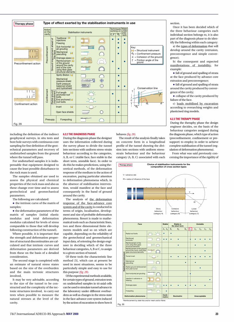
23
including the definition of the indirectgeophysical surveys, in situ tests andbore hole surveys with continuous coresampling for fine definition of the geot-echnical parameters and recovery ofundisturbed samples from the groundwhere the tunnel will pass.
For undisturbed samples it is indis-pensable that equipment designed tocause the least possible disturbance tothe rock mass is used.
The samples obtained are used toassess the physical and chemicalproperties of the rock mass and also asthese change over time and to assessgeotechnical and geomechanicalparameters.
The following are calculated:
• the intrinsic curve of the matrix ofsamples;
• the deformation parameters of thematrix of samples (initial elasticmodulus and total deformationmodulus calculated for levels of stresscomparable to those that will developfollowing construction of the tunnel).
Where possible, it is important thatthe strength and deformation proper-ties of structural discontinuities are cal-culated and that intrinsic curves anddeformation parameters are derivedfrom these on the basis of a detailedconsideration.
The second stage is completed withan estimate of natural stress statesbased on the size of the overburdenand the main tectonic structuresinvolved.
It may be very advisable, accordingto the size of the tunnel to be con-structed and the complexity of the tec-tonic structures involved, to carry outtests when possible to measure thenatural stresses at the level of thecavity.
6.2.2 THE DIAGNOSIS PHASEDuring the diagnosis phase the designeruses the information collected duringthe survey phase to divide the tunnelinto sections with uniform stress-strainbehaviour according to the categories,A, B, or C (stable face, face stable in theshort term, unstable face). In order todo this he makes predictions, using the-oretical methods, of the deformationresponse of the medium to the action ofexcavation, paying particular attentionto deformation phenomena which, inthe absence of stabilisation interven-tion, would manifest at the face andconsequently in the band of groundaround the cavity.
The analysis of the deformationresponse of the face-advance coresystem and of the cavity is conducted interms of origin, localisation, develop-ment and size of probable deformationphenomena. Resort is made to mathe-matical tools such as characteristic lines,two and three dimensional finite ele-ments models and so on which arecapable, depending on the reliability ofthe geotechnical and geomechanicalinput data, of orienting the design engi-neer in deciding which of the threebehaviour categories, A, B or C, to assignto a given section of tunnel.
Of these tools the characteristic linemethod [5], which can at present beused in most situations, seems to beparticularly simple and easy to use forthis purpose (fig. 28).
Of the experimental methods available,for certain types of ground, extrusion testson undisturbed samples in tri-axial cellscan be used to simulate tunnel advance inthe laboratory under different overbur-dens as well as changes in the stress statein the face-advance core system inducedby the action of excavation to show how it
behaves (fig. 28).The result of the analysis finally takes
on concrete form in a longitudinalprofile of the tunnel showing the divi-sion into sections with uniform stress-strain behaviour and the behaviourcategory (A, B, C) associated with each
section.Once it has been decided which of
the three behaviour categories eachindividual section belongs to, it is alsopart of the diagnosis phase to do iden-tify the following within each category:
a) the types of deformation that willdevelop around the cavity (extrusion,preconvergence and simple conver-gence);
b) the consequent and expectedmanifestations of instability, forexample:
• fall of ground and spalling of strataat the face produced by advance coreextrusion and preconvergence;
• fall of ground and spalling of strataaround the cavity produced by conver-gence of the cavity;
• collapse of the cavity produced byfailure of the face.
c) loads mobilised by excavationaccording to overarching weights andplasticised ring models.
6.2.3 THE THERAPY PHASEDuring the theraphy phase the designengineer decides, on the basis of thebehaviour categories assigned during
the diagnosis phase, which type of action(preconfinement, confinement or pre-support) to employ in order to achievecomplete stabilisation of the tunnel (reg-ulation of deformation phenomena).
From what was said previously con-cerning the importance of the rigidity of
T&T International ADECO-RS Approach MAY 2000
σ σ1σ3
c
~Conservation line
Confinement action
Fig. 29
Actionon thecavity
Stabilisation instrumentsTechniquesworking on
Waterunderpres-sure
Traditionalinjections
Sub-horizontal ( )jet-grouting
Freezing
( )
Drainage pipes ( )
Spritz-Breton ( )
Mechanicalpressure shield
Full length ( )
End anchored ( )roof bolts
anchored roofbolts
Earth pressurebalanced shieldand hydroshield
Invert ( )
Open face shields
Presupp. Forepoling
Reinforcement ( )of the groundaround the cavityand of the coreusing fibre glassstructural elements
Mechanicalprecutting ( )
Pre
conf
inem
ent
Con
finem
ent
Gro
und
imp
rove
men
t ah
ead
of
the
face
Rad
ial g
roun
dim
prov
emen
t
σ3c,
Preconfinement action
= Confinement pressure= Cohesion of the ground= Friction angle of the
Key:
ground
σ3
c
( ) = Structural instrument
Type of effect exerted by the stabilisation instruments in useTherapy phase
Therapy phase Choice of stabilisation instruments for thecomposition of cross section types
Fig. 30
Face
Deformation phenomenaCenti-metric Decimetric Unacceptable
Stable Stable inthe short term
Unstable
A1 A2 B1 B3 C1 C2 C3 C4 C5B2
Radial roof bolts
Reinforcedshotcrete *
Reinforcement of thecore using fibre glassstructural elementsReinforcement of the groundaround the cavity using fibreglass structural elements
Radial ground reinforcementfrom pilot tunnel
Sub-horizontal jet-grouting
Injection in advance orfreezing
Drainage pipes
Forepoling
Tunnel invert
Mechanicalprecutting
Sta
bili
sati
on
inst
rum
ent
Stonybehaviour
(category A)
Cohesivebehaviour
(category B)
Loosebehaviour
(category C)
V
Rf
V = advance rate
Rf = radius of influence of the face
*Reinforcement by steel ribs and/or mesh and/or fibres

24
ADECO-RS
the core of ground ahead of the facewith regard to the stress-strain behav-iour of the face and the cavity and there-fore to the stability of the whole tunnel, adesigner has three basic courses ofaction open to him:
• he may limit himself to simple con-finement action in the case of tunnelswith stable face stress-strain behav-iour (category A);
• he has to think in terms of pro-ducing vigorous preconfinementaction - in addition of course to con-finement action - in the case oftunnels with unstable face stress-strain behaviour (category C);
• he may choose between precon-finement or simple confinement ofthe cavity as a function of the rate ofadvance he estimates he can achievein the case of tunnels with the facestable in the short term (category B).Once the type of action to be exerted
has been decided, the action must beperfected in terms of systems, rates,excavation stages and above all stabili-sation methods and tools. For the latter,how and where they are to be employedwith respect to the position of the faceand according to the behaviour cate-gory, A, B or C, involved, must be estab-lished so that the desired action isproduced.
In order to actually produce the typeof action desired in practice, a designengineer has a number of tools available
with which to implement all the neces-sary types of stabilisation.
Keeping in mind that stabilisationmay be of the following types:
• conservation when the main effectis that of containing the relaxation of theminor principal stress;
• improvement when the main actionis that of increasing the shear strength ofthe medium;
of those instruments available to thedesign engineer that produce precon-finement action on the cavity [1] (fig.29), the following exert an essentiallyconservation effect:
• fibre reinforced shotcrete shellscreated by means of mechanical precut-ting along the profile of the tunnel usingthe precutting itself as formwork [3], [10];
• reinforcement of the core ahead ofthe face to a depth not less than thediameter of the tunnel by means of fibreglass tubes or structural elements fixedto the ground with cement mortar; theentity of this operation will depend onhow much the shear strength of the coreis to be increased [3], [10], [11], [12], [13];
• truncated cone umbrellas, con-sisting of subhorizontal columns ofground, side by side, improved by jet-grouting [10], [14].
A mainly improvement action isexerted by:
• truncated cone umbrellas of groundimproved by traditional injections orfreezing;
• truncated cone drainage umbrellas,when working under the water table.
Of those instruments available to thedesign engineer that produce confine-ment action on the cavity, the followingexert a mainly conservation effect:
• a primary lining shotcrete shellcapable of producing confinement pres-sure as a function of its thickness;
• full-face mechanised excavation bymeans of pressurised shields, capable ofproducing confinement pressure on theface and on the cavity (lining ring in pre-fabbricated concrete segments);
• mechanised excavation by means ofopen shields, that furnish radial confine-ment pressure on the ground duringexcavation;
• radial roof bolting performed bymeans of end anchored bolts, whichapply “active” confinement pressure onthe walls of the tunnel, to an extent thatis preset by the tensioning of the bolts;
• invert, which creates a closed liningstructure and multiplies the capacity ofthe primary and secondary linings toproduce very high levels of confine-ment pressure around the cavity.
A mainly improvement action isexerted by:
• a ring of reinforced ground aroundthe cavity, created by means of roofbolts anchored along their full lengthcapable of increasing the shear strengthof the ground involved and raising itsintrinsic curve.
Those tools which fall into neither ofthese two categories because theyproduce neither preconfinement norconfinement action are known as pre-support or support methods accordingto whether they act ahead of the face ornot. They have no effect on the forma-tion of an “arch effect” and are not ableto either contain in any appreciablemanner the relaxation of the minorprincipal stress or to improve the shearstrength of the ground.
An example of one of these presup-port methods is forepoles which,although constituting beams resting onribs installed after excavation andforming a cylindrical configurationrunning along the line of the tunnel, areincapable of producing an arch effectdue to the absence of any reciprocaltransverse action between them.
6.2.3.1 COMPOSITION OF TYPICALLONGITUDINAL AND CROSS SECTIONSIn the preceding paragraphs we haveseen that the stability of face-advancecore system plays a fundamental role inthe deformation response of the mediumto the opening of an underground cavityand consequently in the long and shortterm stability of the tunnel itself. We havealso seen that the stability of this systemcan be described in terms of three funda-mental behaviour categories that charac-terise the type of tunnel to be excavatedfor a given section in terms of a concep-
T&T International ADECO-RS Approach MAY 2000
+A
A
C1 type section with jet-grouting
Steel ribs2 IPN 180/100
Lining of concrete Waterproofing
Waterproofing
Ground improvedby jet-grouting
Ground improvedby jet-grouting
Drainage pipes
Ground improvedby jet-grouting
Shotcrete thickness = 35cm
0.20~8%
Therapy phase
Drainagepipes
13.03.0
1.5ø
L=4.0
2 IPN 180/100
Road level
Road level
<
<
R=6.66
0.2
10.9
66.611.5
4.01.00.50.70.8
0.7
7.6 6.5 1.1
Ø=15.1Fig. 31
Longitudinal section Cross section
Section A - A

25T&T International ADECO-RS Approach MAY 2000
tual framework and that it is completelylogical to refer to these categories whendeciding on stabilisation methodsdesigned to guarantee the stability andsafety of the works.
Taking account of the above, figure30 shows, schematically, the range ofapplicability of the individual stabili-sation instruments available to adesign engineer in the context of theproposed framework. The assembly ofthese will determine the typical longi-tudinal and cross sections designed toguarantee the feasibility of the excava-tions and the long and short term sta-bility of the tunnel. The cases involvedare as follows:
• in sections of tunnel with a stableface (behaviour category: A, stresses: inthe elastic range, typical manifestationsof instability: fall of ground), themethods of stabilisation proposed haveabove all a protective function and aredetermined by the geostructural con-figuration of the ground and by the pos-sible presence of water;
• in sections of tunnel with a facestable in the short term (behaviour cate-gory: B, stresses: in the elastic-plasticrange, typical manifestations of insta-bility: spalling of strata due to extrusion ofthe core, preconvergence and conver-gence of the cavity), the methods of sta-bilisation must guarantee the formationof an arch effect as close as possible to theprofile of the excavation. Instruments are
therefore proposed that are capable ofpreventing the ground from losing itsstrength and deformation propertieswith particular reference to the face-advance core system. Confinement orpreconfinement action is developed thatis sufficient to counter the onset of plasti-cisation of the ground or at least limit theextent of this;
• in sections of tunnel with anunstable face (behaviour category: C,stresses: in the failure range, typical man-ifestations of instability: failure of theface, collapse of the cavity), the methodsof stabilisation must guarantee the for-mation of an artificial arch effect inadvance ahead of the face. Instrumentsfor preconfinement of the cavity aretherefore proposed which, by ensuringthe stability of the face-advance coresystem, prevent the minor principalstress (σ3 from falling to zero, de facto,when deformation phenomena can stillbe controlled.
The table in fig. 30 can therefore beused by the designer as a reference forthe design of typical longitudinal andcross sections.
Fig. 31 shows an example of the com-position of C1 type, longitudinal andcross sections.
6.2.3.2 DESIGN AND ANALYSIS OF TYPICALLONGITUDINAL AND CROSS SECTIONS.SUMMARY OF THE THERAPY PHASEHaving decided the type of action to
ø
ø
ø
5 10
x
15Rf
Rf
V
Longitudinal section
Plan
3
2
5b4b3b2b1b
1
321
6c
5c4c3c2c1c
5b
4b3b2b1b
5a
6a
4a3a2a1a
1c1a
a b c
d
d
xd
5 10 15
Groundlevel
-8.0
0.0
-12.0
-16.0-19.0-21.0-23.0
E FA
BC D
+0.2
0.0
-0.2
-0.4
-0.6
-0.8
15
10
5
0
200
150
100
50
0-4-6 0-2 2 4 6 8 10
x/ø Distance from the face Days
1b
Excavationand castingof the invert
/ø x 10-2
XX
XX
XX
X X XX X
22 Dec 8923 Dec 8928 Dec 893 Jan 906 Jan 90
X
Monitoring phase
0 5 10 15
Extrusion(mm)
Extrusion(mm)
(mm)
0 30 60 90
DBCA
1 2 37÷15
Time (weeks)
30
20
10
0
Stop fittings
035
1246
Fig. 32

T&T International ADECO-RS Approach MAY 200026
ADECO-RS
exert, designed the methods to beemployed to achieve it and composedthe typical longitudinal and cross sec-tions, the design engineer still has thetask of setting the dimensions of thelatter and analysing them using themathematical methods alreadyemployed during the diagnosis phase.Analysing the balance of interventionbetween the face and the perimeter ofthe excavation is of particular impor-tance as is assessing their effectivenesson the basis of the acceptability of thestress-strain behaviour predicted for thetunnel once stabilisation measures havebeen implemented. Naturally the calcu-lations can be carried out resorting tosimple convergence-confinementmodels or, on the other hand, to morecomplex extrusion-confinement orextrusion-preconfinement modelsaccording to the specific stress-strainsituation that is assumed.
In addition to the main (or prevalent)design section types, some derivedsection types may also be designed foruse in statistically probable situations,where, however, the precise locationcould not be predicted on the basis ofthe available data.
The prevalent and derived design sec-tions are in any case defined unequivo-cally in the sense that for each type notonly are the type, intensity, stages andsequence of the construction operationsdescribed in detail, but the geologicaland geomechanical conditions in whichthe design section must be placed are
also clearly identified.The introduction of derived design
sections now allows tunnels to be con-structed in Quality Assurance regime,conforming to ISO 9000 rules [15].
The result of the therapy study is thensummarised on the geomechanicalprofile of the tunnel showing the typicallongitudinal and cross sections to beadopted for each section of the tunnelhaving uniform stress-strain behaviour.
6.2.3.3 THE ADVANCE CORE UNDER THEWATER TABLEAs is known, water under hydrostaticconditions, and even more so underhydrodynamic conditions reduces thestrength and deformation properties ofthe ground considerably. It is alsoknown that a tunnel that advancesunder the water table acts like a hugedrain: a movement is set up wherebywater filters towards the face whichaffects the advance core first. Since aswe have seen the advance core plays akey role in determining the short andlong term stability of a tunnel, it isimportant that water is prevented fromcirculating inside the core. This can beachieved, depending on the specificconditions involved (feed to the watertable, gradients, etc.) by acting system-atically to water-proof the core and thewalls of the cavity (advance underhydrostatic conditions) or by inter-cepting the water three or more tunneldiameters ahead of the face with specialdrainage pipes placed in an umbrella-
shaped configuration around the futuretunnel (advance under hydrodynamicconditions).
In the latter case, in order ensure thatthe treatment ahead of the face does nothave the opposite effect to that desired,it is extremely important that great careis paid to the correct implementation ofthe drainage pipes. These must neverbe inserted into the ground from thesurface of the face. They must always beinserted, in a truncated cone configura-tion, into the ground from the side wallsof the tunnel, or at least from theperimeter of the face so that the core isnever intersected. If this were not done,then the water drawn into them wouldsoak into the advance core with disas-trous effects on its stability and on thatof the entire tunnel. To prevent thisfrom happening, it is important to makesure that the drainage pipes are freefrom perforations for a few meters at theend closest to the tunnel.
Similarly, for the same reason, greatcare must be taken to ensure thatground improvement treatmentinvolving the drilling and then the inser-tion of reinforcement elements into theadvance core is performed correctly. It isimportant that the holes are drilled oneat a time and that they are immediatelyfilled and perfectly sealed with cementmortar. This is the only way to preventthe holes bored from draining waterinto them with devastating conse-quences for the advance core whichonce water-logged and weakened,
would not be able to perform its stabil-ising action effectively.
6.2.4 THE MONITORING PHASEOnce the design moment is complete,the start of construction work (con-struction moment) coincides with thatof monitoring to check the reliability ofpredictions made during the diagnosisand therapy phases in terms of stress-strain behaviour.
This monitoring (which assumesgreat importance, having based theentire design on these predictions) iscarried out by measuring and checkingthe real “response” of the medium tothe action of excavation. The responsemanifests in the form of deformationphenomena:
• inside the cavity, at the face and onthe walls of the excavation;
• on the surface, along the route ofthe tunnel.
To this end, appropriate measure-ment stations are installed ahead of, atand back from the face (fig. 32).
In fact when it is predicted thattunnel advance will occur in short termstable or unstable face conditions, it isparticularly interesting and advisablewhen the tunnel overburden permits,to install multibase vertical instru-ments for a given cross-section beforethe arrival of the face that are designedto measure radial deformation thatprecedes its arrival (preconvergences).
For the face-advance core systemthen, sliding longitudinal micrometers
Analysisof the deformation response of the ground
?
Face
Convergence
NATM and derived methods
Convergence
Behind the face
ADECO - RS
Extrusion of the face
Preconvergence of the cavity
Convergence of the cavity
Ahead and behind the face
Convergence
Advance core
Preconvergence
Extrusion
Fig. 33
Controlof the deformation response of the ground
Fig. 34
NATM and derived methodsby acting only on the cavity
Only confinement action
Radial boltingSteel ribs
ShotcretingInvert
Intervention
ADECO - RSby acting on the strength anddeformability of the advance
core and on the cavity
++ +++
+++ +
A A-A
A-A
A
A
A
Preconfinement and confinementaction
Intervention
Preconfinement of the cavity byprotection of the core
Preconfinement of the cavity byreinforcement of the core
Continuous confinement of the cavitynear the face

27T&T International ADECO-RS Approach MAY 2000
are used to measure extrusion andmultibase radial rod extensometers forconvergence both at the surface of thecavity and at varying distances from it,inside the mass of the ground. Specialtape extensometers are used to checkperimeter convergence back from theface.
The more systematic and thoroughthe monitoring is the more reliable anduseful the information will be for thedesign engineer whose task will bemore or less complex according to therange in which the deformation phe-nomena develop.
If tunnel advance occurs in amedium with stony or loose typebehaviour (categories A or C respec-tively), where forecast deformation isso slight that it does not cause anyworry (cases of lithoid ground underweak to medium overburdens) or sogreat as to be unacceptable and torequire preconfinement intervention(non cohesive ground under any over-burden, clayey and lithoid groundunder large overburdens), the impor-tance of monitoring is reduced becausedeformation phenomena will developrapidly and be limited in entity.Consequently the task of the designengineer is much easier once appro-priate decisions have been made foradequate control of the real situation.
On the other hand, however, thedesign engineer must pay much moreattention and greater care must betaken with the analysis of deformation
of the face-advance core system and ofthe convergence of the cavity both atthe cavity surface and inside theground at a distance from it. Theirdevelopment over time and in spaceshould be followed carefully whenadvance occurs in a medium withcohesive type behaviour (category B).
In this case, deformation phe-nomena will be slow, progressive, anddeferred and of ever increasing entityand the design engineer will only beable to obtain the information neces-sary for optimising the intensity anddistribution of intervention betweenthe face and the cavity on the one handand calibrating stages, rates and exca-vation systems on the other, by contin-uous interpretation of monitoringresults.
Consequently, it cannot be empha-sised too much just how importantcorrect interpretation of the results ofmonitoring is, because the detailedfine-tuning of the design of the excava-tion under construction depends oncorrect interpretation of these results.
During construction, the results ofmonitoring will guide the design engi-neer and the director of work indeciding whether to proceed with thedesign section type as specified ormodify construction quantities(according to criteria specified in thedesign) adopting a derived designsection type allowed for the consideredtunnel section in the design specifica-tions or to proceed with the design of a
new type of design section type in thepresence of particular conditions notdetected at the survey phase and there-fore not provided for by the design.
It is also important to point out thatthe monitoring phase does not endwhen the tunnel is complete, but onthe contrary must continue with sys-tematic monitoring aimed at ensuringthe safety of the tunnel during thewhole of its service life.
7. CONCLUSIONSIf the deformation that is normallyobserved inside a tunnel while it isadvancing is interpreted in terms of aprocess of cause and effect, it wouldseem perfectly reasonable to identify thecause as the action that is exerted on themedium and the effect as the deforma-tion response of the medium, conse-quent to the action.
While on the basis of this assumptionthe cause until only a few years ago wasnot felt worthy of attention nor of in-depth analysis, remaining only appar-ently determined, the effect wasimmediately identified as convergenceof the cavity and it is this that was studied(fig. 33). These studies produced theo-ries, design approaches and constructionsystems that assumed that all the prob-lems connected with tunnel constructioncould be solved by the use of simpleradial confinement action (fig. 34).
Among the former, the “theory of char-acteristic lines” developed by Lombardiand the “convergence-confinement
method” developed by Panet [4], [5] arevery well known. Although they recog-nised for the first time the beneficialeffect of the presence of the core on thestability of the cavity, they neverthelessdid not furnish any effective suggestionson how to exploit the effect nor on how totackle instability of the face.
Among the latter, approaches like theNATM, based on geomechanical classifi-cations (often used for purposes otherthan that for which they were intended)undoubtedly constituted considerableprogress with respect to the past at thetime when they were introduced. Theprincipal merits of the NATM were:
• to consider the ground as a con-struction material for the first time;
• to introduce the use of new tech-nologies of simple active confinement ofthe cavity such as shotcrete and roofbolts;
• to underline the need to systemati-cally measure and interpret the deforma-tion response of the rock mass.
Today, however, having consideredthe statics problems of tunnels exclu-sively as two dimensional problems andconcentrated all attention on conver-gence of the cavity alone, it (and all theapproaches derived from it) shows thefollowing important limitations:
• it is an incomplete and partial clas-sification system, because it is notapplicable to all types of ground and allstress-strain conditions;
• it completely overlooks the impor-tance of the advance core and the need
500
400
300
200
100
(m)
Northernportal
FaultMarseille
Southernportal
Construction times
0 200 400 600 800 1000 1200 1400 1600 1800 2000 2200 2400
5000 1000 1500 2000 2500Limestone-
marly limestones
Heading-benchmethod
Full facemethod
TGV Mediterranee - Tartaiguille tunnel
Stampien clayAlbien sandstones-Aptien blue marls
2338
(m)
Apr 96Jun 96Aug 96Oct 96Dec 96Feb 97Apr 97Jun 97Aug 97Oct 97Dec 97Feb 98Apr 98Jun 98Aug 98Oct 98
By
usin
gA
DEC
O-R
S
By
usin
gA
DEC
O-R
S
Bench
Heading
Roof lining
Fitting out
Completion within 36 months
Scheduled
Keys:
1
2
LimestonesMarlylimestones
Albiensandstones
Aptien bluemarls
UpperStampien
3
45
6
7
LowerStampienmarlyclays
Fig. 35
Paris

T&T International ADECO-RS Approach MAY 200028
ADECO-RS
to use it as a stabilisation instrumentunder difficult stress-strain conditions;
• it ignores new technologies, con-tinuing to propose simple confinementtechniques alone for the stabilisation oftunnels;
• it does not provide a clear distinc-tion between the design moment andthe construction moment of a tunnel;
• it solves the problem of monitoringthe adequacy and correct dimensionsof the design solutions adopted in anindisputably non scientific manner,quite happily comparing the geome-chanical classes with the size of thedeformation response of the ground.
The erroneous conviction that theeffect consequent to the action that isexerted on the medium during tunnelexcavation was identifiable only in theconvergence of the cavity has ledentire generations of engineers downthe wrong path. What was taught bythe design and constructionapproaches fashionable at the time(NATM and derived methods whichstill today act according to this erro-neous conviction) induced them toconcentrate on dealing with theeffects (containing convergence of thecavity by simple confinement action)instead of on the causes of tunnelinstability [16], [17].
This way of tackling the problem wassuccessful for driving tunnels under lowto medium difficulty stress-strain con-ditions but showed its limitations whenfaced with very or extremely difficultconditions because:
1. of the inability to make reliableforecasts of tunnel behaviour duringadvance and therefore of the absence ofa diagnosis phase in the design proce-dure;
2. measures to confine deformationthat was not forecast beforehand wereimprovised;
3. of a lack of effective stabilisationsystems, capable of dealing with thecause of instability (deformation of thecore) and not just the effect (conver-gence);
4. of the inability to make a prelimi-nary assessment of a project in terms offorecasting risks, time schedules andadvance rates.
Given this situation, the rapid andconstantly growing demand for tunnelsof all types, including those under highand extreme stress-strain conditionsurgently required the formulation oftheories and procedures capable ofcontrolling the deformation response ofthe medium under all possible stress-strain conditions and not just under“not difficult” conditions.
In order to get out of this stalled situa-tion it was necessary to bring theproblem back to reality and treat it as athree dimensional problem, which ineffect it is, and to consider the entiredynamics of the tunnel advance processand not just the last phase of theprocess.
It was with this philosophy that theo-
retical and experimental researchstudies commenced which providedthe foundations for a new approachbased on the Analysis of COntrolledDEformation in Rocks and Soils. It hasbeen successfully employed over thelast 10 - 15 years in an extremely widerange of types of ground and stress-strain conditions including the mostdifficult and has been used to solveproblems in numerous extremely diffi-cult situations (see table 1, overleaf)where the application of old concepts(NATM and derived methods), whichdon’t show their limitations or intrinsicdefects in less difficult situations, hadfurnished disappointing and at times
even catastrophic results.In this respect, it is perhaps impor-
tant to consider, in the conclusion, theevents that occurred in France duringthe construction of the Tartaiguilletunnel for the new “TGV Méditerranèe”,Marseilles to Lyons high speed rail line.
Tunnel advance with a 180 sq. m.cross section, began in February 1996and proceeded with varying successaccording to NATM principles untilSeptember of the same year when theheavily swelling “argile du Stampien”formation (75% montmorillonite) wasencountered and increasing difficultieswere such that continuation of theworks was practically impossible. In
order to solve the problem at the start of1997 the SNCF (Societè National duChemin de Fer) set up a study group(“Comité de Pilotage”) consisting ofengineers from the French Railways,engineers from the G.I.E. Tartaiguilleconsortium, the consulting engineersCoyne et Bellier and CETU, consultinggeotechnical engineers from theTerrasol and Simecsol consortium. Thisgroup in turn consulted majorEuropean tunnelling experts invitingthem come up with a design solution tocross the clayey formation safely and onschedule.
After examining several proposals,none of which offered the guarantees of
σ
τ
B
A
C
Characterisation of the mediumin terms of the rock and soil mechanics
Determination of the behaviour categories(A,B,C)
based on predictions of the stability of the coreahead of the face using mathematical methods
Choice of confinement and/or preconfinement actionto be exerted
according to the behaviour category (A,B,C)
Choice of confinement and/or preconfinementtechnologies
based on recent technological developments
Composition of typical sections(longitudinal and cross sections)
Design and analysis of typical sectionsin terms of convergence-confinement, extrusion-confinement
and extrusion-preconfinement
Implementation of stabilisation methodsin terms of confinement and/or preconfinement
Checking the accuracy of the predictions madeduring the diagnosis and therapy phases
by interpreting deformation phenomena as the responseof the medium to the advance of the tunnel
Final design adjustmentsby balancing action between the face and the cavity
Monitoring the safety of the tunnel during its working life
∆r
P
Survey phase
Operational phase
Monitoring phase
Diagnosis phase
Therapy phase
Des
ign
inst
rum
ent
dr
Fig. 36

29T&T International ADECO-RS Approach MAY 2000
safety and reliability requested by theclient, above all with regard to comple-tion times, the SNCF were attracted bythe proposal put forward by myself con-taining hypothesised constructiontimes and costs guaranteed on the basisof similar cases successfully solved. InMarch 1997, Rocksoil S.p.A. wasawarded the contract for detaileddesign of the 860 m. of tunnel still to becompleted.
Tunnel advance resumed in July 1997after radical revision of the designaccording to A.DE.CO.-RS principles(full face tunnel advance, see photo 4)and was finally able to continue withoutinterruptions and with growing success
as the site operators gradually gainedconfidence in the use of the new tech-nologies. Exceptionally constantaverage advance rates were recorded(fig. 35), which as guaranteed by theconsulting engineers were higher than1.4 m. per day allowing the tunnel to becompleted in July 1998 after only oneyear since work began with the newsystem and one month ahead ofschedule [18], [19], [20].
In the light of the considerable expe-rience acquired over the last ten years[3], [12], [13], [20], [21], it can be confi-dently stated that the A.DE.CO.-RSapproach to the design and construc-tion of tunnels can be used to produce
virtually linear advance rates indepen-dently of the type of ground tunnelledand the contingent stress-strain condi-tions. It follows that while it was onceonly possible to talk of mechanisationunder conditions that could be dealtwith by simple confinement of thecavity or of the face (shields, TBMs),today mechanisation can be spoken ofeven under more complex and difficultconditions which require preconfine-ment action. Tunnel excavation canfinally be industrialised (constantadvance rates, accurate forecasting oftimes and costs) independently of thetype of ground and the size of the over-burden involved.
To summarise, by making full use ofthe most recent knowledge, calculatingpower and advance technologies (fig.36) the A.DE.CO.-RS approach offersdesign and construction engineers asimple guide with which tunnels can beclassified in one of three fundamentalbehaviour categories. To do this, refer-ence is made to the stability of the face-advance core system which is predictedby means of in-depth stress-strainanalysis performed theoretically usingmathematical tools. For each section oftunnel with a uniform deformationbehaviour identified in this manner, thedesign engineer decides the type ofaction (preconfinement or simple con-finement) to produce in order to controldeformation and, as a consequence,selects the type of stabilisation tech-nique and the longitudinal and trans-verse tunnel section type mostappropriate to each given situation, byusing the suited instruments to developthe necessary actions. Tunnel sectiontypes are available for all types of groundand stress-strain condition. Costs andconstruction times (per linear metre)can be automatically calculated for eachof these.
By using this approach:
• importance is given to stabilisationtechniques as indispensable instru-ments for controlling and regulatingdeformation, and hence as “structuralelements” for the purposes of the finalstability of a tunnel (tunnels are seen interms of, and paid for in proportion to,how much they deform). In this respectit is worth noting that on the cost side ofincome statements for undergroundprojects, stabilisation and groundimprovement works are the only itemswhich vary significantly as compared toexcavation and lining items whichincreasingly tend to remain constant forall types of ground (fig. 37);
• with a complete and reliable designthe main contractor is induced to indus-trialise tunnel advance operations in alltypes of ground, even the most difficult;
• given the ability to plan construc-tion times and costs, disputes whichuntil very recently arose between theClerk of Works and contractors areavoided;
• by employing one single referenceparameter, common to all types ofground (the stress-strain behaviour ofthe face-advance core system), that canbe easily and objectively measuredduring tunnel advance, the problem ofthe clearest and most evident defect ofprevious classification systems (com-paring geomechanical classes with thedeformation response of the ground),which until today fuelled disputesbetween Clerks of Works and contrac-tors, is solved.
As a result of these important charac-teristics, the A.DE.CO.-RS approach hasaroused considerable interest andrapidly established itself as an advanta-geous alternative to those employed todate. In this respect the decision to use it
17.5
15
12.5
10
7.5
5
2.5
0
Unit costs for the Malenchini and Rimazzano tunnels
Face Unstable Stable in the short term Stable
Pric
es p
er m
etre
of t
unne
l
Final design
As built
Fig. 37
Total cost
Ground im
provement
Lining
Excavation
(103
/m
)

T&T International ADECO-RS Approach MAY 200030
ADECO-RS
for drawing up the design specificationson the basis of which contracts wereawarded and then the constructiondesign of the new Bologna to FlorenceHigh Speed Rail line was particularly sig-nificant. At the moment it certainly con-stitutes the largest tunnel constructionproject in the world: approximately 84.5km. of tunnel with a cross section of 140sq. m. on a route with a total length of 90km through notoriously difficult grounddue to its variability and often very poorgeomechanical properties. Despite thedifficult conditions, contracts for theworks were awarded on a “turnkey”basis in which the contractor evidentlyfelt that the design was sufficiently com-plete and reliable to accept all the risks,including geological risks. At presentmore that 30% of the works, whichbegan in July 1998, are now completeand full face advance (see photo 5) isproceeding simultaneously on 32 facesat an average advance rate of approxi-mately 1,600 m./month of finishedtunnel [21] [22].
While the art of designing and con-structing tunnels has perhaps lost someof its fascination with the demand toplan, it has certainly gained with theintroduction of the A.DE.CO.-RSapproach, in efficiency and function-ality, while neither restricting nor condi-tioning the imagination. �
BIBLIOGRAHY[1] LUNARDI P., “Aspetti progettuali ecostruttivi nella realizzazione di galleriein situazioni difficili: interventi di pre-contenimento del cavo”, InternationalConference on “Rock and SoilImprovement in Underground Works” -Milan, 18th - 20th March 1991[2] LUNARDI P., “Avanza la galleriameccanica” - Le Strade, May 1996[3] LUNARDI P., BINDI R., FOCARACCIA., “Nouvelles orientation pour le projet etla construction des tunnels dans des ter-rains meubles. Études et expériences sur lepréconfinement de la cavité et la précon-solidation du noyau au front”, ColloqueInternational “Tunnels et micro-tunnelsen terrain meuble”, Paris, 7-10 février1989[4] PANET M., “Le calcul des tunnels parla méthode convergence-confinement”,Ponts et chaussées, 1995[5] LOMBARDI G., AMBERG W.A., "Uneméthode de calcul élasto-plastique del'état de tension et de déformation autourd'une cavité souterraine", Congresso
Internazionale ISRM, Denver, 1974[6] LUNARDI P., “The influence of therigidity of the advance core on the safetyof tunnel excavation”, Gallerie e grandiopere sotterranee, no. 52, 1997 (Italianand English)[7] LUNARDI P., “Conception et exécu-tion des tunnels d’après l’analyse desdéformations contrôlées dans les roches etdans les sols - First part: Présoutenementet préconfinement”, (Italian and French),Article in three parts: Quarry andConstruction, March 1994, March 1995,April 1996 or Revue Francaise deGeotechnique, no.80, 1997, no.84, 1998,no. 86, 1999[8] LUNARDI P., "Lo scavo delle galleriemediante cunicolo pilota", Politecnico diTorino, Primo ciclo di conferenze di mec-
canica e ingegneria delle rocce - Turin,25th-26th November 1986[9] CAMPANA M., LUNARDI P., PAPINIM., "Dealing with unexpected geologicalconditions in underground construction:the pilot tunnel technique", Acts of 6thEuropean Forum on "Cost Engineering" -Università Bocconi, Milan, 13th-14thMay 1993, Vol. 1[10] LUNARDI P. et al., "Soft groung tun-nelling in the Milan Metro and MilanRailway Link. Case histories", SoftGround Tunnelling Course - Institutionof Civil Engineers - London, 10th-12thJuly 1990[11] LUNARDI P. et al., "Tunnel face rein-forcement in soft ground design and con-trols during excavation", InternationalCongress on "Towards New Worlds in
Tunnelling" - Acapulco 16-20 Maggio1992 [12] LUNARDI P., "Fibre-glass tubes tostabilize the face of tunnels in difficultcohesive soils", SAIE : Seminar on "Theapplication of fiber Reinforced Plastics(FRP) in civil structural engineering" -Bologna, 22 Ottobre 1993[13] LUNARDI P., "La stabilite du frontde taille dans les ouvrages souterrainesen terrain meuble: etudes et experiencessur le renforcement du noyau d'avance-ment", Symposium international"Renforcement des sols: experimentationsen vraie grandeur des annes 80", Parigi,18 novembre 1993[14] LUNARDI P., Evolution des tech-nologies d'escavation en souterrain dansdes terrains meubles", Comité Marocaindes Grands Barrages - Rabat, 30Settembre 1993[15] LUNARDI P., FOCARACCI A.,“Quality Assurance in the Design andConstruction of Underground Works”,International Congress on “UndergroundConstruction in Modern Infrastructure”,Stockholm, 7th-9th June 1998[16] KOVARI K., "On the Existence ofNATM, Erroneous Concepts behindNATM", Tunnel, no. 1, Year 1994 (Englishand German), or Gallerie e Grandi OpereSotterranee, n. 46, 1995 (Italian andEnglish).[17] LUNARDI P., “Convergence-con-finement ou extrusion-préconfinement?”, Colloque “Mécanique etGéotechnique”, Laboratoire deMécanique des Solides - ÉcolePolytechnique, Paris 19 mai 1998[18] ANDRE D., DARDARD B.,BOUVARD A., CARMES J., “La traverséedes argiles du tunnel de Tartaiguille”,Tunnels et ouvrages souterrains, no. 153,May-June 1999[19] LUNARDI. P., “The “Tartaiguille”tunnel, or the use of the A.DE.CO.-RSapproach in the costruction of an “impos-sible” tunnel”, Gallerie e grandi opere sot-terranee, no. 58, August 1999 (Italian andEnglish)[20] MARTEL J., ROUJON M. MICHELD., “TGV Méditerranèe - Tunnel deTartaiguille: méthode pleine section”,Proceedings of the InternationalConference on “Underground works:ambitions and realities”, Paris, 25th -28th October 1999[21] LUNARDI P., “The Bologna toFlorence high speed rail connection.Design and construction aspects of theunderground works”, Gallerie e grandiopere in sotterraneo, no. 54, 1998 (Italianand English)[22] “Florence to Bologna at high speed”,Tunnels and Tunnelling International,April 1999
Photo 5: Pianoro Tunnel (Italy, Bologna to Florence High Speed Rail Line,ground: cemented silty sand, overburden: 150 m, tunnel diameter: 13.30 m.).View of the face reinforced with fibre-glass structural elements.
Photo 4: Tartaiguille Tunnel (France, Marseille to Lyon TGV Méditerranèe, ground:swelling clay (75% montmorillonite), overburden: 100 m, tunnel diameter: 15 m.).View of the face (180 m2) reinforced with fibre-glass structural elements.
TUNNEL YEAR Ø [m] GROUND OVERBURDEN ADVANCE RATES max [m] [m/day] average ÷ max
“Tasso” (Florence to Arezzo Railway Line) 1988 12,20 Sandy silts 50 2,0 ÷ 3,2“Targia” (Bicocca to Syracuse Railway Line) 1989 12,00 Hyaloclastites 50 2,0 ÷ 3,3“San Vitale” (Caserta to Foggia Railway Line) 1991 12,50 Scaly clays 100 1,6 ÷ 2,4“Vasto” (Ancona to Bari Railway Line) 1993 12,20 Silty sand and clayey silt 135 1,6 ÷ 2,6“Tartaiguille” (Marseille to Lyon TGV Méditerranèe) 1996 15 Swelling clay 110 1,4 ÷ 1,9“Appia Antica” (Rome Outer Ring Motorway) 1999 20,65 Sandy gravelly pyroclastites 18 2.3+3.3
Table 1st. The application of design and construction criteria stated by ADECO-RS approach enabled us to achieve con-siderable successes, including the salvage of tunnels whose excavation by other means proved to be impossible. Someof the above mentioned tunnels are listed below:
ROCKSOIL S.p.APiazza San Marco, 1I-20121 Milano (Italy)
Tel. +39 02 65 54 323Fax. +39 02 65 97 021Web site: http://www.rocksoil.com