addp-me-ed0003571 - fermilab · web viewafter all flanges are partially assembled, install all...
TRANSCRIPT

CONTROLLED DOCUMENTUsers are responsible for ensuring they work to the latest approved revision released
within Teamcenter. Printed or electronically transmitted copies are uncontrolled and may be obsolete.
ACCELERATOR DIVISION DEPARTMENTAL PROCEDURE
AD/MECHANICAL SUPPORT DEPARTMENT
ADDP-ME-ED0003571
PRODUCING VERY LOW-PARTICULATE UHV COMPONENTS
REVISION VERSION: [-] REVISION ISSUE DATE: [09/10/2015]
Originating Author: R. Kellett / (Electronic Signature on TC file)* Date: (date on TC file)*(Print) (Sign)
Revising Author: N/A / Date:(Print) (Sign)
Approver: M. Wong-Squires / (Electronic Signature TC file)* Date: (date on TC file)*(Print) (Sign)
* Electronic Signature and date on Teamcenter (TC) item signoff report (Audit File)REVIEW AND CONCURRENCE RECORD

REVIEWED BY: L. Nobrega / (Electronic Signature on TC file)* Date: (date on TC
file)* Rev: -
(Print) (Sign)
REVIEWED BY: A. Chen / (Electronic Signature on TC file)* Date: (date on TC
file)* Rev: -
(Print) (Sign)
REVIEWED BY: C. Baffes / (Electronic Signature on TC file)* Date: (date on TC
file)* Rev: -
(Print) (Sign)
REVIEWED BY: M Bonkalski / (Electronic Signature on TC file)* Date: (date on TC
file)* Rev: -
(Print) (Sign)

REVIEWED BY: K. Kosirog / (Electronic Signature on TC file)* Date: (date on TC
file)* Rev: -
(Print) (Sign)
REVIEWED BY: G. Lauten / (Electronic Signature on TC file)* Date: (date on TC
file)* Rev: -
(Print) (Sign)
REVIEWED BY: R. Lewis / (Electronic Signature on TC file)* Date: (date on TC
file)* Rev: -
(Print) (Sign)
ACKNOWLEDGED BY:: D. Franck / (Electronic Signature on TC file)* Date: (date on TC
file)* Rev: -
(Print) (Sign)
ACKNOWLEDGED BY: D. Bonifas / (Electronic Signature on TC file)* Date: (date on TC
file)* Rev: -
(Print) (Sign)
REVIEWED BY: L. Valerio / (Electronic Signature on TC file)* Date: (date on TC
file)* Rev: B
(Print) (Sign)

TABLE OF CONTENTS
1.0 PURPOSE AND SCOPE 5
2.0 SAFETY PRECAUTIONS 5
3.0 GENERAL CLEANROOM PROCEDURES 5
3.1 PRE-CLEAN AREA (Outside of cleanroom) 5
3.2 PARTS CLEANING AREA (Class 10,000) 5
3.3 PARTICULATE CERTIFICATION AREA (class 100) 5
3.4 ASSEMBLY AREA (Class 10) 6
3.5 HOUSE KEEPING 6
3.6 DEIONIZED WATER 7
3.7 ULTRASONIC TANKS 7
4.0 SPECIFIC MATERIAL INSTRUCTIONS (Detailed) 7
4.1 NIOBIUM 7
4.2 STAINLESS STEEL 8
4.3 COPPER 9
4.4 ALUMINUM 9
4.5 SPECIFIC MATERIAL INSTRUCTIONS (Summarized) 10
5.0 FIELD ASSEMBLY 12
5.1 PORTABLE CLEANROOM 12
6.0 RADIOACTIVE PARTS CLEANING 13
6.1 CLEANING 13
6.2 DRYING 13
6.3 STORAGE 13

FLOW CHART FOR CLEANING STAINLESS HARDWARE 14
FLOW CHART FOR CLEANING STAINLESS PARTS 15
FLOW CHART FOR CLEANING Sl-BRONZE HARDWARE 16

1. PURPOSE AND SCOPEThe purpose of this procedure is to establish and define the steps necessary to produce low particulate vacuum parts connected to superconducting RF cavity beam tubes. This procedure covers general cleanroom requirements, specific material cleaning instructions, and details of cleanroom assembly techniques. It also covers radioactive parts cleaning.
2. SAFETY PRECAUTIONS Wear appropriate eye and hand protection when handling ultrasonic soaps and degreasers. NEVER immerse any part of your body into an ultrasonic bath while the ultrasonic is on. Use hearing protection when the ultrasonic tanks are on and when blowing off parts with the anti-static gun.
3. GENERAL CLEANROOM PROCEDURESThe stockroom Tyvek® garments are not to be used in a cleanroom. Only use garments that are certified for cleanroom use. After ultrasonic cleaning and rinsing, dry the parts off inside the Class 10,000 cleanroom using an antistatic dry Nitrogen gun prefiltered to 0.003 μm until dry. Move the part to the class 100 area and blow each part off using an antistatic dry Nitrogen gun prefiltered to 0.003 μm into a particle counter until the count is zero on all scales. After blowing off each part, it should be assembled or stored in a Nitrogen flushed, sealed clear nylon double bag covered by a sealed anti-static pink poly bag. If the parts are small, they should be individually packaged to prevent contact with each other that would generate particles during handling. A special bagging note for parts cleaned for use in portable cleanrooms. Bag with one sealed clear nylon bag next to the cleaned part, followed by a sealed anti-static pink poly bag.
3.1. PRE-CLEAN AREA (Outside of cleanroom)3.1.1. To help maintain cleanliness of the area, wipe dry shoes on floor mat, also step on the tack mat
until no visable trace is noticed before entering area. If shoes are wet, cover them with booties.3.2. PARTS CLEANING AREA (Class 10,000)
3.2.1. The minimum protective clothing required in the Class 10,000 room is shoe covers, lab coat, and gloves.
3.2.2. Clean all of the parts, including seals, hardware, and tools before starting to assemble.3.2.3. A special note on cleaning copper gaskets; only wipe the gasket with isopropyl alcohol and
alphasorb or D.I. and isopropyl premoistened wipers. Never use any type of abrasive scrubbers. Then blow them to 0 particles and triple bag individually.
3.3. PARTICULATE CERTIFICATION AREA (class 100)3.3.1. Upon entering the antechamber of the Class 10/100 cleanroom, don the following cleanroom
approved items in this order; long cuffed shoe covers (over existing shoe covers), a pair of long cuffed latex gloves, hood, facemask, coveralls, and another pair of long cuffed latex gloves.
3.3.2. Do not touch your face or glasses with your gloved hand. Change or clean the gloves when assembling fastners, before handling the next part.
3.3.3. Move slowly upon entering the assembly area of the Class 100 cleanroom. Keep arm movements to a minimum to reduce the amount of particulate coming from them.
3.3.4. The perforated blow-off table is located just inside the cleanroom entrance. Wipe down the blow-off table with a moist cleanroom wiper and blow it dry with filtered, clean, nitrogen from the anti-static gun.
3.3.5. For freshly cleaned and dried parts, blow off one part at a time with filtered, clean, nitrogen from the anti-static gun with a steady, slow movement. Position the particulate counter horn in a manner that will allow it to collect the blow-by gas coming past the part. Turn on the particulate counter. The particle count must read 0 counts on all scales.
3.3.6. For previously bagged parts, open the outter bag and discard it, open the inner bag and change or clean your gloves. Place the part on the perforated table. Blow the part using the anti-static nitrogen gun with a steady, slow movement. Blow off all sides of the part. Continue dusting until the particulate counter reads 0 counts on all scales.
3.3.7. After blowing off the part, move it to the class 10 side of the cleanroom to await assembly or it should be assembled or stored as decribed in step 3. If the parts are small, they should be individually packaged to prevent contact with each other that would generate particles during handling.
3.4. ASSEMBLY AREA (Class 10)

3.4.1. Before entering the Class 10 cleanroom; clean the latex gloves with moistened cleanroom wipers and blow them off.
3.4.2. No bagged parts are allowed in the 10 cleanroom. Wet fasteners with clean, new ethyl alcohol before use to reduce free-floating particulates. After handling fasteners, clean your gloves before handling another gasket or part.
3.4.3. When assembling or disassembling components, if possible, connect the mass flow control vent up manifold and set the flow to 2500 sccm; if optical transistion radiation (OTR) foils are in the vacuum space, set the flow rate to 150 sccm. This flow rate will provide a controlled purge to help prevent particulates from entering the chamber.
3.4.4. Assembling conflat flanges:3.4.4.1. Tighten two cleaned and blown fastners opposite of each other on the same flange just enough
to secure the gasket. If there is more than one flange to assemble, repeat the process on all flanges. After all flanges are partially assembled, install all other fasteners and tighen them to spec.
3.4.4.2. Using the mass flow controlled vacuum cart, leak check the assembly before removing it from the cleanroom. The sensitivity of the RGA must be at least 2e-10 atm*cc/s for helium or 1.0e-11 Amps.
3.4.4.3. All flange gaps should be covered with polyolefin cleanroom tape to prevent dust from collecting in the leak check channel. Any flange that will be opened in the near future must be completely covered with a cleanroom bag sealed with polyolefin cleanroom tape to minimize particle contamination. Note, if possible, double bag the sub-assembly before being removed from the cleanroom.
3.4.5. Disassembling conflat flanges:3.4.5.1. Choose two fasteners on small flanges and three fasteners on flanges 6” and larger that are
diametrically opposed to each other on the horizontal plane and remove them. If there is more than one flange to disassemble, repeat the process on all flanges.
3.4.5.2. Blow off the flange(s), concentrating on the empty bolt holes with filtered, clean, nitrogen from the anti-static gun. Position the particulate counter horn in a manner that will allow it to collect the blow-by gas coming past the flange(s). Turn on the particulate counter. Blow until the particulate counter reads 0 counts on all scales.
3.4.5.3. Replace the removed fastners with clean, blown, fastners and snug them up. Now remove all remaining original fasteners. Before blowing off the part, check to make sure the pressure in the device is holding by verifying that the flow on the mass flow controller is zero. If a leak is detected, tighten the replaced two (or three) bolts until the leak stops.
3.4.5.4. Blow off the flange(s) concentrating on the empty bolt holes. Position the particulate counter horn in a manner that will allow it to collect the blow-by gas coming past the flange(s). Turn on the particulate counter. Blow until the particulate counter reads 0 counts on all scales. After blowing off the flange(s), remove them while maintaining a mass flow controlled purge on the part if possible.
3.5. HOUSE KEEPING3.5.1. Remove clutter (used wipes, scotchbrite pads, etc.) from the cleanroom and pre-clean areas. The
cleanroom must always be in an organized state. After tools (wrenches, pliers, screwdrivers, etc. have been used they are to be considered contaminated. They must be cleaned before the next use and sealed in a single layer clear nylon bag to prevent particle generation in storage.
3.5.2. At least once a day, when the cleanroom is being used, all entrance mats and the staging room floor should be cleaned. They should be vacuumed first to remove large particles, then mopped with a solution of TexClean cleanroom floor soap, followed by wet vacuuming.
3.5.3. If parts are soaking in the sink, make a note of the solution and whom the parts belong to on the white board.
3.6. DEIONIZED WATER3.6.1. Measure the DI water for five bacteria once a week: Hetero m-HPC, P2P Pseudomonas,
Yeast&Mold m-Green, Tryptone Glucose Extract w/TTC, M-ENDO Total Coliform. The counts should be below 10 on each sample after a 48-hour incubation.
3.6.2. Resistivity must be better than 12MΩ.

3.6.3. Total Oxidizable Carbons must be less than 10 PPM. Counts slightly above ten can be accepted due to error and fluxuations.
3.7. ULTRASONIC TANKS3.7.1. Maintain a current record of the type of solution in each tank. The record should include the
makeup date, cleaner used, and a detailed list of items cleaned in each tank. 3.7.2. The pH of any wastewater must always be checked before emptying the tank. Wastewater with a
pH equal to or below 2.0 or equal to or above 12.5 are considered hazardous waste and may not be discharged without further treatment (neutralization) and review / approval from the ESHQ/ Environmental Protection Group. However, if the pH of the wastewater is between 2.0 and 5.5, or between 9.0 and 12.5 and all other discharge criteria are met in accordance with both the FESHM Chapter 8025, Wastewater Discharge to Sanitary Sewers and ADSP-08-0203 Procedure, then the wastewater may be released to a sanitary sewer at a rate not to exceed 50 gallons per day. Wastewater with pH range from 5.5 to 9.0 can be released without restrictions if all other discharge criteria are met. If these criteria are not met, store the wastewater in an approved poly container and contact the ESHQ/ Environmental Protection Group for guidance and proper disposal. Weblink to the ESHQ
3.7.3. The soap tank solution should be changed only when the product is deemed to be used up by titrimetry testing.
3.7.4. The D.I. rinse tanks should be changed every day during use.3.7.5. After draining the tank, clean the ultrasonic tank using a nylon bristle brush and rinse thoroughly
with DI water.3.7.6. Fill the freshly cleaned tank with DI water.3.7.7. Use the appropriate soap solution for the material being cleaned as described in section 4.0 of this
document. Carefully measure the amount of soap at the recommended rate labled on each ultrasonic tank.
3.7.8. For critical parts, the final ultrasonic rinse water resistivity should be 12MΩ or greater. If 12MΩ cannot be achieved, make sure ultrasonic tank is as clean as possible. Use clean water. Use no solvents. Distribute nitrogen in the tank with the special fixture. De-gas water for 5 minutes when parts are added. Do not place the resistivity monitor in the water during the de-gas cycle.
3.7.9. For very sensitive parts where ultrasonics cannot be used, it is acceptable to soak parts in the appropriate cleaner for up to 1 hour. This process may need to be repeated a few times to ensure cleanliness. Water agitation via circulation is beneficial to remove soils from the material surface in cases where ultrasonics cannot be used.
4. SPECIFIC MATERIAL INSTRUCTIONS (Detailed)
The following sections describe in detail the steps for particle-free cleaning of niobium, stainless steel, copper, and aluminum parts. These steps are summarized in Table 1. It is importaint to use the correct cleaner with the specific material described, otherwise damage to the part will result. Measure the concentration ratio of all cleaners accurately if the tank doesn’t have a stricker with the right amount affixed to it.
4.1. NIOBIUM4.1.1. Follow all of section 3.1.4.1.2. Inspect parts for damage. Pre-clean parts with a clean room wiper or nylon brush (including pipe
cleaning brushes), in a clean container using SimpleGreenCrystalClear® and cool DI water. Thoroughly rinse the parts with DI water. Be careful not to damage the sealing surfaces of flanges or other fragile parts. For stubborn stains, white Scotch-Brite™ may be used, but not on sealing surfaces.
4.1.3. Use a clean ultrasonic tank filled with DI water and 2% solution of Micro90® cleaner. The heater should be set to 65°C. Ultrasonics should only be used for 30 minutes or less. Make sure the parts do not contact the tank walls during the cleaning process. It is acceptable to pre-soak parts for up to 2 hours without the ultrasonic on.
4.1.4. Remove the soapy parts from the ultrasonic tank, don’t let the soap dry on the part. Immediately pre-rinse the part with DI water or soak in secondary poly container to submerge the parts in fresh DI water during pre-rinsing.

4.1.5. Remove the part from the rinse tank and check if the part shows signs of water beading up. If the part is clean the part should look wet on all surfaces, if not follow step 4.1.5.1. If part is fully wetted skip 4.1.5.1 Inspect part for damage.
4.1.5.1. Use an additional ultrasonic bath with fresh Citranox® solution if cleaning an especially dirty critical part. The addition of an acid based cleaner provides additional cleaning for soils that Micro-90® doesn’t work so well on, and also helps to remove the Micro-90® itself.
4.1.6. Use a clean ultrasonic tank filled with DI water. The heater should be set to 65°C. Ultrasonics should only be used for 30 minutes or less. Make sure the parts do not contact the tank walls during the rinsing process. It is acceptable to soak parts without the ultrasonic on. Inspect part for damage.
4.1.7. Remove the part from the rinse tank and check if the part shows signs of water beading up. If the part is clean the part should look wet on all surfaces, if not repeat previous steps. If part is fully wetted continue.
4.1.8. Remove the parts from the rinse tank and immediately start to dry them under the HEPA filter in the class 10,000 area. Use the anti-static nitrogen gun to blow off the remaining water. Concentrate on areas that tend to trap water, such as knife-edges and holes. Continue blowing until no water remains.
4.1.9. Immediately after drying, seal them in a nylon bag described in section 3. or store them in a nitrogen desiccator until ready to use. If the parts are to be e-beam welded, follow the next step.
4.1.10. For parts going to be e-beam welded, immediately store them in a nitrogen purged desiccator until ready to weld. Place all parts in shipping containers.
4.2. STAINLESS STEEL4.2.1. Follow all of section 3.1.4.2.2. Inspect parts for damage, especially knife-edges. Pre-clean parts with a cleanroom wiper or poly
brush in a clean container, using SimpleGreenCrystalClear® and heated DI water. Thoroughly rinse the parts with DI water. Be careful not to damage the sealing surfaces of flanges or other fragile parts. For stubborn stains, white Scotch-Brite™ may be used, but not on sealing surfaces.
4.2.3. Use a clean ultrasonic tank filled with DI water and 2% solution of Micro90® cleaner. The heater should be set to 65°C or turned on depending on the unit. Ultrasonics should only be used for 30 min or less. Make sure the parts do not contact the tank walls during the cleaning process. It is acceptable to pre-soak parts for up to 2 hours without the ultrasonic on.
4.2.4. Remove the soapy parts from the ultrasonic tank, don’t let the soap dry on the part. Immediately pre-rinse with DI water or soak in secondary poly container to submerge the parts in fresh DI water during pre-rinsing.
4.2.5. Remove the part from the rinse tank and check if the part shows signs of water beading up. If the part is clean the part should look wet on all surfaces, if not follow step 4.2.5.1. If part is fully wetted skip, 4.2.5.1. Inspect part for damage.
4.2.5.1. Use an additional ultrasonic bath with fresh Citranox® solution if cleaning an especially dirty, critical part. The addition of an acid based cleaner provides additional cleaning for soils that Micro-90® doesn’t work so well on, and also helps to remove the Micro-90® itself.
4.2.6. Remove the soapy parts from the ultrasonic cleaner. Immediately pre-rinse with DI water or soak in secondary poly container to submerge the parts in fresh DI water during pre-rinsing. Do not let the soap dry on the part. Inspect part for damage.
4.2.7. Use a clean ultrasonic tank filled with DI water. The heater should be set to 65°C. Ultrasonics should only be used for 30 minutes or less. Make sure the parts do not contact the tank walls during the rinsing process. It is acceptable to soak parts without the ultrasonics on.
4.2.8. Remove the part from the rinse tank and check if the part shows signs of water beading up. If the part is clean the part should look wet on all surfaces, if not repeat previous steps. If part is fully wetted continue.
4.2.9. After inspecting the parts immediately start to dry them. Use the anti-static nitrogen gun to blow off the remaining water. Concentrate on areas that tend to trap water such as knife-edges and holes. Continue blowing until no water remains. Immediately after drying, seal them in a nylon bag described in section 3.
4.3. COPPER4.3.1. Follow all of Section 3.

4.3.2. Pre-clean parts with a clean room wiper or poly brush as needed, in a clean container, using SimpleGreenCrystalClear® and cool DI water. Thoroughly rinse the parts with DI water. Be careful not to damage the sealing surfaces of flanges or other fragile parts. For stubborn stains, white Scotch-Brite™ may be used, but not on sealing surfaces.
4.3.3. Using a clean ultrasonic tank, or poly tank depending on part sensitivity to ultrasonics, filled with DI water and 2% solution of Citronox® cleaner. The heater should be off. Ultrasonics should only be used for 3 minutes or less. Make sure the parts do not contact the tank walls during the cleaning process. It is acceptable to pre-soak parts for up to 1 hour without the ultrasonic on.
4.3.4. Remove the parts from the ultrasonic tank. Immediately pre-rinse the soapy part with DI water or soak in secondary poly container to submerge the parts in fresh DI water during pre-rinsing. Inspect part for damage.
4.3.5. Rinse parts using a clean ultrasonic tank filled with DI water. The heater should be off. Ultrasonics should only be used for 3 minutes or less. Make sure the parts do not contact the tank during the rinsing process.
4.3.6. Remove the part from the rinse tank and check if the part shows signs of water beading up. If the part is clean the part should look wet on all surfaces, if not, repeat previous steps. If part is fully wetted continue.
4.3.7. Dry the parts using the anti-static nitrogen gun to blow off the remaining water. Concentrate on areas that tend to trap water such as knife-edges and holes. Continue blowing until dry.
4.3.8. Immediately after drying, seal them in a nylon bag described in section 3.4.4. ALUMINUM
4.4.1. Follow all of section 3.1. 4.4.2. Inspect parts for damage, especially knife-edges. Pre-clean parts in a clean container, using
SimpleGreenCrystalClear® and cool DI water with a clean room wiper or poly brush as needed. Thoroughly rinse the parts with DI water. Be careful not to damage the sealing surfaces of flanges or other fragile parts. For stubborn stains, white Scotch-Brite™ may be used, but not on sealing surfaces.
4.4.3. Using a clean ultrasonic tank, or poly tank depending on part sensitivity to ultrasonics, filled with DI water and 2% solution of Citronox® cleaner at room temperature. Ultrasonic cleaners should only be used for 3 minutes or less. Make sure the parts do not contact the tank walls during the cleaning process. It is acceptable to pre-soak parts for up to 1 hour without the ultrasonics on.
4.4.4. Remove the parts from the ultrasonic tank. Immediately rinse the soapy part with DI water or soak in secondary poly container to submerge the parts in fresh DI water during rinsing. Inspect parts for damage.
4.4.5. Rinse using a clean ultrasonic tank filled with DI water. The heater should be off. Ultrasonics should only be used for 3 minutes or less. Make sure the parts do not contact the tank or poly tank walls during the rinsing process.
4.4.6. Remove the part from the rinse tank and check if the part shows signs of water beading up. If the part is clean the part should look wet on all surfaces, if not repeat previous steps. If part is fully wetted continue.
4.4.7. Remove the parts from the rinse tank and immediately dry them using the anti-static nitrogen gun to blow off the remaining water. Concentrate on areas that tend to trap water such as knife-edges and holes. Continue blowing until no water remains. Immediately after drying, seal them in a nylon bag described in section 3.
4.5. SPECIFIC MATERIAL INSTRUCTIONS (Summarized)

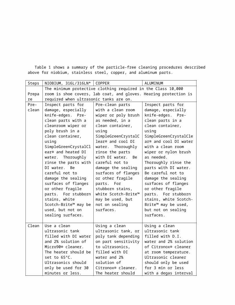
Table 1 shows a summary of the particle-free cleaning procedures described above for niobium, stainless steel, copper, and aluminum parts. Steps NIOBIUM, 316L/316LN* COPPER ALUMINUM Prepare The minimum protective clothing required in the Class 10,000 room is shoe covers, lab coat, and
gloves. Hearing protection is required when ultrasonic tanks are on.Pre-clean
Inspect parts for damage, especially knife-edges. Pre-clean parts with a cleanroom wiper or poly brush in a clean container, using SimpleGreenCrystalClear® and heated DI water. Thoroughly rinse the parts with DI water. Be careful not to damage the sealing surfaces of flanges or other fragile parts. For stubborn stains, white Scotch-Brite™ may be used, but not on sealing surfaces.
Pre-clean parts with a clean room wiper or poly brush as needed, in a clean container, using SimpleGreenCrystalClear® and cool DI water. Thoroughly rinse the parts with DI water. Be careful not to damage the sealing surfaces of flanges or other fragile parts. For stubborn stains, white Scotch-Brite™ may be used, but not on sealing surfaces.
Inspect parts for damage, especially knife-edges. Pre-clean parts in a clean container, using SimpleGreenCrystalClear® and cool DI water with a clean room wiper or nylon brush as needed. Thoroughly rinse the parts with DI water. Be careful not to damage the sealing surfaces of flanges or other fragile parts. For stubborn stains, white Scotch-Brite™ may be used, but not on sealing surfaces.
Clean Use a clean ultrasonic tank filled with DI water and 2% solution of Micro90® cleaner. The heater should be set to 65°C. Ultrasonics should only be used for 30 minutes or less. Make sure the parts do not contact the tank walls during the cleaning process. It is acceptable to pre-soak parts for up to 2 hours without the ultrasonic on. Remove the soapy parts from the ultrasonic tank. Do not let the soap dry on the part.
Using a clean ultrasonic tank, or poly tank depending on part sensitivity to ultrasonics, filled with DI water and 2% solution of Citronox® cleaner. The heater should be off. Ultrasonics should only be used for 3 minutes or less. Make sure the parts do not contact the tank walls during the cleaning process. It is acceptable to pre-soak parts for up to 1 hour without the ultrasonic on.
Using a clean ultrasonic tank filled with D.I. water and 2% solution of Citronox® cleaner at room temperature. Ultrasonic cleaner should only be used for 3 min or less with a degas interval of 1 minute (US off). Make sure the parts don’t contact the tank walls during the cleaning on process. It is acceptable to pre-soak parts for up to 1 hour without the ultrasonic on.
Inspect/Pre-Rinse
Remove the soapy parts from the ultrasonic tank. Do not let the soap dry on the part. Immediately pre-rinse the part with DI water or soak in secondary poly container to submerge the parts in fresh DI water during pre-rinsing. Remove the part from the rinse tank and check if the part shows signs of water beading up. If the part is clean the part should look wet on all surfaces.
Remove the parts from the ultrasonic tank. Immediately pre-rinse the soapy part with DI water or soak in secondary nylon container to submerge the parts in fresh DI water during pre-rinsing. Inspect part for damage.
Rinse,Post-Rinse
Use a clean ultrasonic tank filled with D.I. water. The heater should be set to 150°F
Use a clean ultrasonic tank filled with D.I. water. The heater should be off. Ultrasonics should only be used for 3 min or less with a degas interval of 1 minute (US off). Make sure the parts

or turned on depending on the unit. Ultrasonic cleaners should only be used for 30 min or less. Make sure the parts don’t contact the tank walls during the rinsing on process.
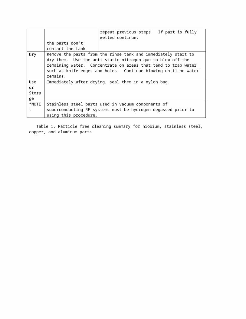
don’t contact the tank walls during the rinsing on process.Remove the part from the rinse tank and check if the part shows signs of water beading up. If the part is clean the part should look wet on all surfaces, if not repeat previous steps. If part is fully wetted continue.
Dry Remove the parts from the rinse tank and immediately start to dry them. Use the anti-static nitrogen gun to blow off the remaining water. Concentrate on areas that tend to trap water such as knife-edges and holes. Continue blowing until no water remains.
Use orStorage
Immediately after drying, seal them in a nylon bag.
*NOTE:
Stainless steel parts used in vacuum components of superconducting RF systems must be hydrogen degassed prior to using this procedure.
Table 1. Particle free cleaning summary for niobium, stainless steel, copper, and aluminum parts.

ADDP-ME-ED0003571 Rev. [-]Page 13 of 17
5. FIELD ASSEMBLY
5.1. PORTABLE CLEANROOMS5.1.1. Setup the anti-static nitrogen gun gas supply from a LN2 dewar with a high flow regulator set to
90 to 95 psi. Purge the flow for a few minutes to purge the lines of air.5.1.2. Connect the nitrogen supply to the anti-static gun that has a particulate filter installed at the gas
inlet.5.1.3. Clean the area encompassing the work zone. Clean the entire area that will be exposed to the
cleanroom with cleanroom curtain cleaner and Alphasorb® wipers. Do not use tape on cleanroom walls.
5.1.4. Blow down the entire cleanroom area down with the anti-static Nitrogen gun and clean the floor. 5.1.5. Don the following items in this order: a pair of long cuffed latex gloves, shoe covers, facemask,
hood, labcoat, and second pair of long cuffed latex gloves. 5.1.6. Check the cleanroom for Class 100 cleanroom compliance with the particle counter.5.1.7. Replace outer glove layer with a new pair and clean them.5.1.8. When using bagged parts, the bag should only be opened inside the cleanroom moments before
using the parts. Avoid cross contamination by not touching the dirty outside of the bag with gloved hands and then touching the clean part.
5.1.9. After opening the inner bag and exposing the part, check for particulates by blowing on the part into a particle counter in a direction away from any opening or particle free part. The part should read no higher than the background of the cleanroom.
5.1.10. When assembling or disassembling components, if possible, connect the mass flow control vent up manifold and set the flow to 2500 sccm; if optical transistion radiation (OTR) foils are in the vacuum space, set the flow rate to 150 sccm. This flow rate will provide a controlled purge to help prevent particulates from entering the chamber.
5.1.11. When assembling conflat flanges, tighten two cleaned and blown off fastners opposite of each other on the same flange just enough to secure the cleaned and blown off, gasket. If there is more than one flange to assemble, repeat the process on all flanges. After all flanges are partially assembled, install all other fasteners and tighen them to spec.
5.1.12. When disassembling conflat flanges, choose two fastners on small flanges, and three fasteners on flanges larger than 6”, diametrically opposed to each other on the horizontal plane and remove them. If there is more than one flange to disassemble, repeat the process on all flanges before opening the first flange. Position the particulate counter horn in a manner that will allow it to collect the blow-by gas coming past the flange(s). Turn on the particulate counter and dust off the flange(s) concentrating on the holes. After dusting the flange(s), install new particle free fastners in the open holes and snug them firmly. Remove all other original fasteners. Dust off the flange(s) consentrating on the open holes. After dusting the flange(s), remove the replacement fastners from the flange(s) while maintaining a purge on the part if possible when opening the flange(s).
5.1.13. When assembling two clean beamtube assemblies together, do not blow off the flanges if the bore is exposed.
5.1.14. When assembling KF flanges of the MFC hose, start a nitrogen purge through the hose before removing the blank-off. Place a pre-cleaned and blown off o-ring, coming from below the flange on the cleaned hose end. Guide the hose and o-ring to the cleaned mating flange. Once the o-ring is placed, every effort should be made to prevent the flanges from slipping or separating. Place the clean & blown clamp with the hinge at 3 o'clock or 9 o'clock and the wing nut screw connected to the top half of the clamp and tighten the clamp as usual.
5.1.15. When removing KF flanges of the MFC hose, start a nitrogen purge through the hose before removing the clamp. Before removing the clamp, wipe and blow the outside of the clamp concentrating on the wing nut and hinge. Loosen the wing nut far enough to completely clear the bottom half of the clamp. Flip the top half off, while holding the bottom half on the KF and applying pressure to the hose preventing the assembly from separating. Wipe the exposed top half
Accelerator DivisionMechanical Support Department
CONTROLLED DOCUMENTUsers are responsible for ensuring they work to the latest approved revision released within Teamcenter. Printed or electronically
transmitted copies are uncontrolled and may be obsolete.
ADDP-ME-ED0003571 Rev. [-]Page 14 of 17
of the KF flange only where the clamp contacts the flange. (The clamp doesn't touch the o-ring side of the KF flange). Remove the clamp. Install a clean and blown o-ring & blank-off on the cleaned valve first and cleaned hose end, then place a clean & blown clamp with the hinge at 3 o'clock or 9 o'clock and the wing nut screw connected to the top half.
6. RADIOACTIVE PARTS CLEANING
Radioactive parts must be checked for contamination by radiation safety before any cleaning takes place. Radiation Safety is responsible for decontaminating the part. All work performed on radioactive parts require personnel to have rad worker training. Personnel must wear TLD and dosimeters, and gloves.
6.1. CLEANING6.1.1. If cleaning tools/implements such as brushes and cloths, etc., are used to preclean parts, they must
be kept in a separate container so an RCT can check them for radioactivity.6.1.2. Using an ultrasonic tank reserved only for radioactive cleaning follow the cleaning steps in
Section 4. 6.1.3. Radiation Safety must check the water and filters before draining to sewer. Note: PH must meet
criteria in section 3.6.2.6.1.4. Using a ultrasonic tank follow the rinsing steps in Section 4.
6.2. DRYING6.2.1. If possible, hang the part to be dried. Remove the parts from the rinse tank and immediately dry
them. Use the anti-static Nitrogen gun to blow off the remaining water. Concentrate on areas that tend to trap water such as knife-edges and holes. Continue blowing until no water remains.
6.3. STORAGE6.3.1. If the parts are to be stored: immediately after drying, seal them in a nitrogen flushed, sealed,
nylon bag described in section 3. 6.3.2. Attach the appropriate radiation sticker to the outside bag according to the survey performed by
Radiation Safety.
Accelerator DivisionMechanical Support Department
CONTROLLED DOCUMENTUsers are responsible for ensuring they work to the latest approved revision released within Teamcenter. Printed or electronically
transmitted copies are uncontrolled and may be obsolete.

ADDP-ME-ED0003571 Rev. [-]Page 15 of 17
Accelerator DivisionMechanical Support Department
CONTROLLED DOCUMENTUsers are responsible for ensuring they work to the latest approved revision released within Teamcenter. Printed or electronically
transmitted copies are uncontrolled and may be obsolete.
ADDP-ME-ED0003571 Rev. [-]Page 16 of 17
Accelerator DivisionMechanical Support Department
CONTROLLED DOCUMENTUsers are responsible for ensuring they work to the latest approved revision released within Teamcenter. Printed or electronically
transmitted copies are uncontrolled and may be obsolete.

ADDP-ME-ED0003571 Rev. [-]Page 17 of 17
Accelerator DivisionMechanical Support Department
CONTROLLED DOCUMENTUsers are responsible for ensuring they work to the latest approved revision released within Teamcenter. Printed or electronically
transmitted copies are uncontrolled and may be obsolete.