additive manufacturing: state-of-the-art, capabilities ...560827/fulltext02.pdf · additive...
TRANSCRIPT

Additive Manufacturing:
State-of-the-Art, Capabilities, and Sample
Applications with Cost Analysis
in Collaboration with
by
MINA ALIAKBARI
Master of Science Thesis, Production Engineering and Management, Department of Industrial Production,
KTH
June 2012

1
Abstract
Additive Manufacturing – AM – which is a part of a generic term, Rapid Prototyping,
comprises a family of different techniques to build 3D physical objects sequentially stacking
a series of layers over each other. These techniques have been evolving over three decades
with more materials available, improving the techniques as well as generating new ones.
However they are all based on the same explained idea.
In this research the main AM methods followed with the opportunities of application and cost
drivers is sought. For this purpose, after reviewing different processes and techniques, the
application of them in diverse industry sectors is described. The influence of AM in
production systems, so called Rapid Manufacturing (RM) is also discussed in terms of lean
and agile concepts. Time and cost are the most important factors for the production systems
to be responsive and productive respectively. Thus, case based application of RM is
evaluated to clarify how AM acts in different production systems regarding these factors.
To decide which method is the best, strongly depends on the case. But what has been derived
from the analysis, is that however in comparison with traditional methods, AM applies more
economically in one-off jobbing, yet the economy of scale exists to some extent. In fact it
depends on the machine capacity utilization as well as batch size which indicates the machine
volume usage.
Despite all the improvements in the last three decades, the application of AM is still not
widespread. Since the demand, use, applications and materials as well as its techniques are
still in a growing phase, a brighter future is seen for the upcoming customer oriented market.
Key Words: Additive Manufacturing, Rapid Manufacturing, Rapid Prototyping, Lean, Agile,
Leagile, Solid Freeform Fabrication, Tooling, Customization, Design Freedom, additive layer
manufacturing,
2
Sammanfattning
Additive Manufacturing – AM – som är del av en generell term, Rapid Prototyping, består av
en familj olika tekniker för att bygga 3D fysiska objekt genom att sekventiellt lägga lager
ovanpå varandra. Dessa tekniker har utvecklats över de senaste tre decennierna, där nya
material blivit tillgängliga, teknikerna har förbättrats och nya har skapats, men i slutändan
bygger de alla på en och samma idé.
Det projekt undersöks de huvudsakliga AM-metoderna, deras applikationer och
kostnadsdrivare. Här görs först en litteraturstudie av olika tekniker och processer varefter
deras användning inom olika industrier undersöks. Den influens AM har i produktionssystem,
s.k. Rapid Manufacturing (RM), diskuteras också i förhållande till lean och agila koncept.
Eftersom tid och kostnad är de viktigaste faktorerna för tillgänglighet respektive
produktivitet utvärderas case-baserad användning av RM utifrån dessa faktorer för att
förklara hur AM fungerar i produktionssystem.
Att besluta vilken metod som är bäst, är starkt case-baserad. Men det som framkommit från
analysen är att i jämförelse med traditionella metoder, är AM mer ekonomiskt vid
enstyckstillverkning, men stordriftsfördelar finns i någon utsträckning. Faktiskt det beror på
maskinens kapacitetsanvändning och satsstorlek som indikerar maskinens volymanvändning.
Trots alla förbättringar under de senaste tre decennierna är användandet av AM ännu inte
utbrett. Eftersom efterfrågan, användning, tillämpning och material så väl som dess tekniker
fortfarande befinner sig i en tillväxtfas spås en ljusare framtid för en växande kundorienterad
marknad.
Nyckelord: Additive Manufacturing, Rapid Manufacturing, Rapid Prototyping, Lean, Agile,
Leagile, Solid Freeform Fabrication, Tooling, Customization, Design Freedom, additive layer
manufacturing
3
Acknowledgments
I would like to offer my special thanks to Mr Per Johansson and Mr Pau Mallol who inspired
me with the concept and guided me in order to complete this thesis research. I also appreciate
all other people who helped me in this research path.
Mina Aliakbari
Royal Institute of Technology
June 2012

4
Dedication
I sincerely dedicate this thesis to my father and mother who are my best teachers of love and
maturity.

5
Contents
1. Introduction .................................................................................................................................. 7
1.1. Definition of Concept .............................................................................................................. 7
1.2. Problem definition .................................................................................................................. 8
1.3. Research scope and boundaries .............................................................................................. 8
1.4. Research methodology ........................................................................................................... 9
2. Additive Manufacturing Methods ................................................................................................ 10
2.1. Plastic Methods .................................................................................................................... 10
2.1.1. Streolithography Apparatus (SLA) ................................................................................... 10
2.1.2. Selective Laser Sintering (SLS)......................................................................................... 13
2.1.3. Fused Deposition modelling (FDM): ................................................................................ 15
2.1.4. Three Dimensional Printing (3DP): .................................................................................. 17
2.2. Metal Methods ..................................................................................................................... 20
2.2.1. Direct Metal Laser Sintering (DMLS) ............................................................................... 20
2.2.2. Selective Laser Melting (SLM) ......................................................................................... 21
2.2.3. Electron Beam Melting (EBM)......................................................................................... 22
2.2.4. EasyCLAD ....................................................................................................................... 24
2.2.5. Laser Consolidation (LC) ................................................................................................. 25
2.2.6. LaserCusing .................................................................................................................... 26
2.2.7. Laser Engineered Net Shaping (LENS) ............................................................................. 28
2.2.8. Digital Part Materialization (ProMetal) ........................................................................... 30
2.2.9. Other Methods............................................................................................................... 32
3. Capabilities and Opportunities ..................................................................................................... 33
3.1. Overview .............................................................................................................................. 33
3.2. Direct part manufacturing ................................................................................................... 35
3.2.1. Consumer products ........................................................................................................ 36
3.2.2. Industrial Products ......................................................................................................... 38
3.2.3. Tooling ........................................................................................................................... 38
3.3 Rapid Manufacturing ............................................................................................................. 40
3.3.1. Design freedom .............................................................................................................. 40
3.3.2. Mass Customization ....................................................................................................... 41
3.3.3. Added functionality ........................................................................................................ 42

6
3.3.4. Process improvements ................................................................................................... 42
3.3.5. Environmental drivers .................................................................................................... 43
4. Rapid Manufacturing in Supply Chain........................................................................................... 44
4.1. RM Overview ........................................................................................................................ 44
4.2. Supply Chain Principles ......................................................................................................... 45
4.3. Why RM can contribute in supply chain principals? ............................................................... 47
5. Application Cases, Cost Analysis and Discussion ........................................................................... 51
5.1. Overview .............................................................................................................................. 51
5.2. Application Case 1: Medical Implant Industry (Jaw Implant) .................................................. 54
5.3. Application Case 2: Aerospace industry (Compressor Impeller) ............................................. 57
5.4. Application Case 3: Cell phone Accessories (Bumper) ............................................................ 59
5.5. Discussion ............................................................................................................................. 61
6. Conclusions and Recommendations ............................................................................................. 66
6.1. Conclusions........................................................................................................................... 66
6.2. Further Researches ............................................................................................................... 69
References ...................................................................................................................................... 70
APPENDICES .................................................................................................................................... 74
Appendix A .................................................................................................................................. 75
Appendix B .................................................................................................................................. 77
Appendix C .................................................................................................................................. 81
Appendix D .................................................................................................................................. 85
Appendix E .................................................................................................................................. 89
7
1. Introduction
1.1. Definition of Concept
Additive Manufacturing (AM) is defined as the manufacturing process of building objects
adding material to previous build areas, layer upon layer, as opposed to subtractive
manufacturing methodologies, such as traditional machining. Synonyms are additive
fabrication, additive techniques, additive layer manufacturing, layered manufacturing and
solid freeform fabrication. It’s also good to mention that AM includes all applications of the
technology, including modeling, prototyping, pattern-making, tool-making, and the
production of end-use parts in volumes of one to thousands or more. It isn’t just about
prototyping as it were for almost two decades since layered manufacturing techniques started
to be used.
Nowadays Rapid Prototyping (RP) on the other side comprises AM and other non-additive
methods for manufacturing physical objects at usually high speed and with part features and
properties that use to be aimed at some kind of testing but normally, not as a final part.
Actually, the American Society for Testing and Materials (ASTM) is normalizing the AM
field, i.e. creating a new 3D generic file format for it called (*.amf) to substitute STL and
others (IGS, STEP…) and provide new parameters that emerging new AM machines need to
exploit their capabilities (e.g. colours, so that the operator doesn’t need to pre-process the file
for the Zcorp case). However, since AM is a very large subset of RP and because RP was
synonym of additive or layered manufacturing since this manufacturing technique appeared,
nowadays they are still used as synonyms of each other in practice. In this thesis the term AM
is used.

8
All the companies are looking for better responsiveness, because what is important is
customer, and what is important for the customer is to get what they ask for (including
function, aesthetics or competitive prices but also, for example, recyclability or energetically
efficient products). Companies seek to find better methods and improvements. In the
competitive market, customer-based production is what companies have in mind. That’s why
a lot of researches have been done to improve and extend methods and techniques.
The first techniques for AM became available in the late 1980s. It is generally considered that
the approach was born in 1987 when 3D Systems developed the Stereo-Lithography
Apparatus (SLA). They were first used to produce models and prototype parts. Today, they
are used for a much wider range of applications; from medical equipment to industrial
products but in relatively small amount. The evolution of the methods for this technique
generated new methods with improved function and material.
1.2. Problem definition
The main feature of AM methods is their flexibility in the design of a product which makes
these methods responsive for almost any shape. Nevertheless the surface quality and
production time and material limitations are examples of its barriers through worldwide
implementation. On the other side, AM is known to be more economical when only one or
few amount of a product is needed to be produced (because it doesn’t require investment e.g.
for process and tooling design). This is another reason of its limited application. In this
research it is investigated how AM can be improved to address any production strategy under
the concepts such as production volume and cost. In other words how such parameters
influence on using an AM approach in medium and large production volume. Thus, by
investigating cost drivers, it is aimed to see if economy of scale exists for this technique.
1.3. Research scope and boundaries
Currently, diverse techniques and diverse machines of AM system are running. This research
has introduced some of them which stand up for a well elaboration of this technique.
However for each of them, the current available material sector and some machine-product
specifications are represented, but the evaluation of the techniques based on these
characteristics and analysis over their improvements are out of the scope of this project. This
9
project has used these data to get insight of the techniques for the aim of cost analysis over
case studies.
1.4. Research methodology
The presented research is conducted as:
First it is investigated the common AM methods and techniques. Important features,
advantages and disadvantages of each method are overviewed. The aim is to ease the
comparison of investigated methods, for instance, in terms of material, build volume or the
method itself.
Later on, the barriers and trends are introduced. The application of AM in different sectors of
production (e.g. industry or consumer products) is investigated. A generic definition of Rapid
Manufacturing (RM), as a capable application of AM, as well as the benefits that AM can
provide for it are described, such as design freedom and process improvements.
The following part of this thesis introduces RM in more detail. Some supply chain principles
is also discussed to introduce different production statuses; lean, agile and leagile.
Furthermore the compatibility of RM in those statuses in addition to the benefits that it brings
for them is analyzed.
The next chapter presents a basic characterization of the products, for example in terms of
material or production volume. This is done to investigate AM/RM in some products to find
out its benefits and limitations over production of chosen product categories. In other words,
this investigation is done to show the importance of analyzing RM techniques case by case to
see its applicability and/or weaknesses. This analysis is followed by an analysis over cost
drivers and the performance of variable changes in the total cost of production.
Finally conclusions are provided about AM’s feasibility on production systems and aspects to
make AM more feasible for conditions where now it is still not optimal is pointed out,
suggesting future areas were specific research can be done to address the actual bottlenecks.

10
2. Additive Manufacturing Methods
In this chapter the most widely used method of AM for plastic and metal material separately
is represented, including the explanation of the techniques, material coverage, and some
range of specification on machines. In some methods non-reliable data or not found records
have been replaced by “-“.
2.1. Plastic Methods
2.1.1. Streolithography Apparatus (SLA)
Process:
Streolithography Apparatus (SLA) produces physical 3D objects, conceptual models or
master patterns from a 3D CAD file. Support structures are either manually or automatically
designed.
In this method, a controlled laser is used to cure a photopolymer resin to shape the product
from a 3D CAD model. First a movable (in Z direction) table is set right under the surface of
a vat filled with a photosensitive resin of the required material. The property of such a resin is
that it gets hard from liquid to solid when the light of a correct color is radiated to it. SLA
common resins normally require ultraviolet light, but visible light is also used for some of
materials. The laser beam, then scans and hardens the material thorough the cross section of
object by moving in X-Y direction.
The process is done in a sealed box to avoid the fumes to come out. Once a layer is cured,
the table lowers at a distance of the defined layer thickness. Although the resin can cover the
surface of the previous layer itself slowly, but to speed this process up, SLA machines use
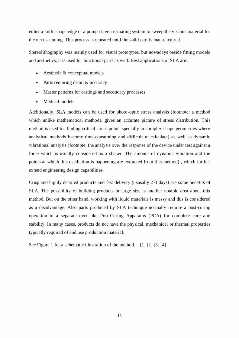
11
either a knife shape edge or a pump-driven recoating system to sweep the viscous material for
the next scanning. This process is repeated until the solid part is manufactured.
Stereolithography was mainly used for visual prototypes, but nowadays beside fitting models
and aesthetics, it is used for functional parts as well. Best applications of SLA are:
Aesthetic & conceptual models
Parts requiring detail & accuracy
Master patterns for castings and secondary processes
Medical models.
Additionally, SLA models can be used for photo-optic stress analysis (footnote: a method
which unlike mathematical methods, gives an accurate picture of stress distribution. This
method is used for finding critical stress points specially in complex shape geometries where
analytical methods become time-consuming and difficult to calculate) as well as dynamic
vibrational analysis (footnote: the analysis over the response of the device under test against a
force which is usually considered as a shaker. The amount of dynamic vibration and the
points at which this oscillation is happening are extracted from this method) , which further
extend engineering design capabilities.
Crisp and highly detailed products and fast delivery (ususally 2-3 days) are some benefits of
SLA. The possibility of building products in large size is another notable area about this
method. But on the other hand, working with liquid materials is messy and this is considered
as a disadvantage. Also parts produced by SLA technique normally require a post-curing
operation in a separate oven-like Post-Curing Apparatus (PCA) for complete cure and
stability. In many cases, products do not have the physical, mechanical or thermal properties
typically required of end use production material.
See Figure 1 for a schematic illustration of the method. [1] [2] [3] [4]
12
Figure 1: Stereolithography
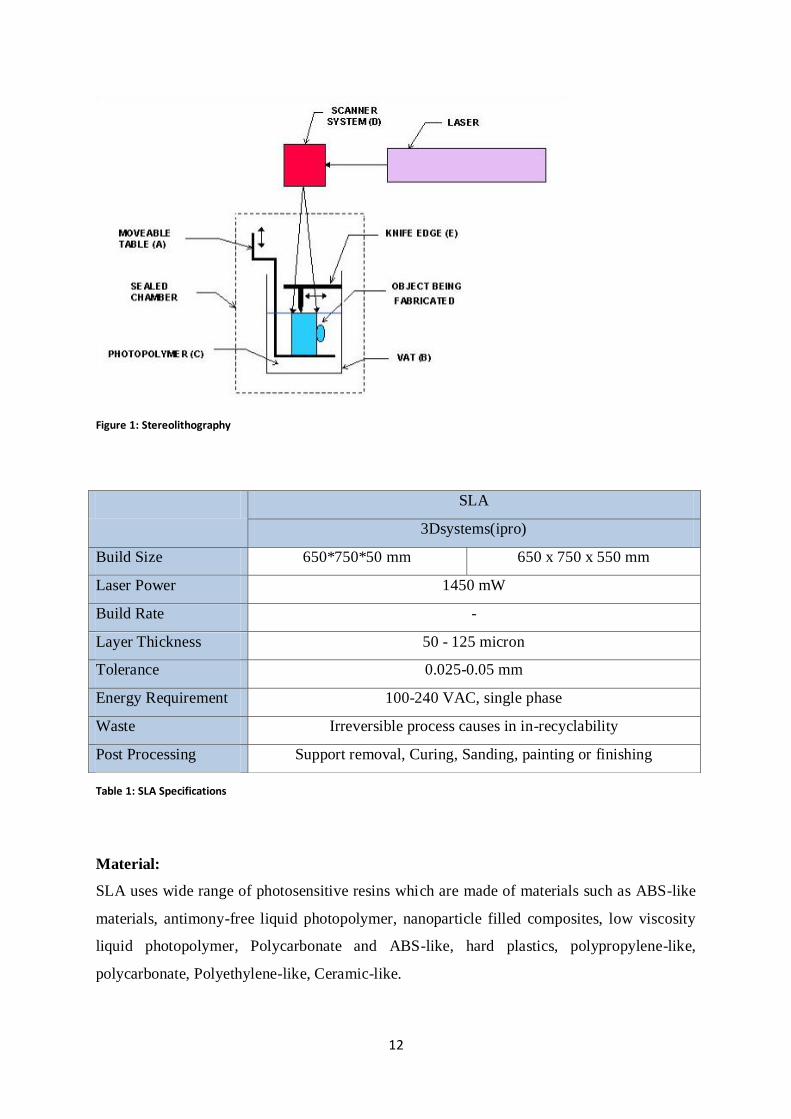
Material:
SLA uses wide range of photosensitive resins which are made of materials such as ABS-like
materials, antimony-free liquid photopolymer, nanoparticle filled composites, low viscosity
liquid photopolymer, Polycarbonate and ABS-like, hard plastics, polypropylene-like,
polycarbonate, Polyethylene-like, Ceramic-like.
SLA
3Dsystems(ipro)
Build Size 650*750*50 mm 650 x 750 x 550 mm
Laser Power 1450 mW
Build Rate -
Layer Thickness 50 - 125 micron
Tolerance 0.025-0.05 mm
Energy Requirement 100-240 VAC, single phase
Waste Irreversible process causes in in-recyclability
Post Processing Support removal, Curing, Sanding, painting or finishing
Table 1: SLA Specifications
13
These photopolymers have specifications; some are transparent, while others are opaque or
even colored. Some are chemical resistant, while others are water resistant or temperature
tolerant. [5] [6]
Notes:
a specific extra-large envelope size is also provided (iPro 9000XL) with build
envelope of 1500 x 750 x 550 mm with accuracy of +/- 0.2mm
2.1.2. Selective Laser Sintering (SLS)
Process:
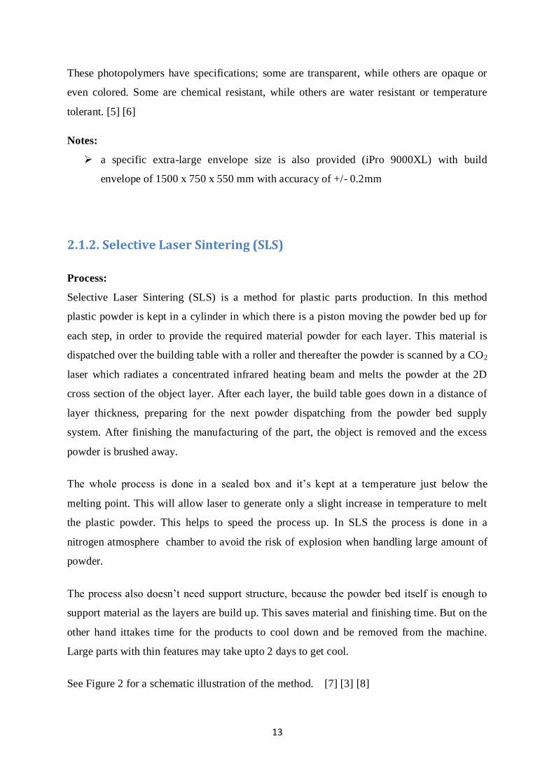
Selective Laser Sintering (SLS) is a method for plastic parts production. In this method
plastic powder is kept in a cylinder in which there is a piston moving the powder bed up for
each step, in order to provide the required material powder for each layer. This material is
dispatched over the building table with a roller and thereafter the powder is scanned by a CO2
laser which radiates a concentrated infrared heating beam and melts the powder at the 2D
cross section of the object layer. After each layer, the build table goes down in a distance of
layer thickness, preparing for the next powder dispatching from the powder bed supply
system. After finishing the manufacturing of the part, the object is removed and the excess
powder is brushed away.
The whole process is done in a sealed box and it’s kept at a temperature just below the
melting point. This will allow laser to generate only a slight increase in temperature to melt
the plastic powder. This helps to speed the process up. In SLS the process is done in a
nitrogen atmosphere chamber to avoid the risk of explosion when handling large amount of
powder.
The process also doesn’t need support structure, because the powder bed itself is enough to
support material as the layers are build up. This saves material and finishing time. But on the
other hand ittakes time for the products to cool down and be removed from the machine.
Large parts with thin features may take upto 2 days to get cool.
See Figure 2 for a schematic illustration of the method. [7] [3] [8]
14
Figure 2: Selective Laser Sintering
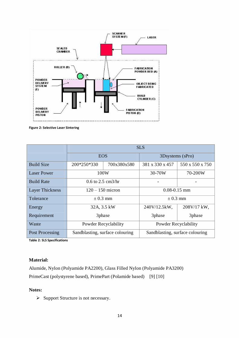
SLS
EOS 3Dsystems (sPro)
Build Size 200*250*330 700x380x580 381 x 330 x 457 550 x 550 x 750
Laser Power 100W 30-70W 70-200W
Build Rate 0.6 to 2.5 cm3/hr - -
Layer Thickness 120 – 150 micron 0.08-0.15 mm
Tolerance ± 0.3 mm ± 0.3 mm
Energy
Requirement
32A, 3.5 kW
3phase
240V/12.5kW,
3phase
208V/17 kW,
3phase
Waste Powder Recyclability Powder Recyclability
Post Processing Sandblasting, surface colouring Sandblasting, surface colouring
Table 2: SLS Specifications
Material:
Alumide, Nylon (Polyamide PA2200), Glass Filled Nylon (Polyamide PA3200)
PrimeCast (polystyrene based), PrimePart (Polamide based) [9] [10]
Notes:
Support Structure is not necessary.

15
2.1.3. Fused Deposition modelling (FDM):
Process:
Fused Deposition modelling (FDM) is the second most AM after Stereolithography.
In this method a plastic filament, approximately 1.5mm in diameter (or in some machinery
configurations plastic pellets fed from a hopper) is unwounded from a coil. This filament
supplies the material to the nozzle at which it gets warmer and melts. The nozzle moves over
the building table at the layer 2D geometry and relieves the extruded plastic and lets it deposit
over the build table. The melted plastic gets hard immediately after depositing from the
nozzle and bonds to the previous layer. Support structures are made with the same method to
prevent overhangs.
The entire system is maintained at a temperature just below melting point, so it lets the nozzle
to provide only a slight increase in temperature to melt the plastic filament and extrude it.
This lets the process be faster and better controlled. FDM is used for functional prototypes
and prototypes for form and fit testing.
See Figure 3 for a schematic illustration of the method. [11] [12] [13]
Figure 3: Fused Deposition Modelling

16
FDM
Fortus Dimension
Build Size 356x254x254 914x610x914 203 x 203 x 305 254 x 254 x 305
Laser Power - -
Build Rate 2.54 cm3/hr -
Layer Thickness 127 upto 330 micron 127 upto 330 micron
Tolerance (mm) +/- .0015 upto ± .241
Energy
Requirement
230VAC, 16 A, 3phase 110-120 VAC/ 15A or 220-240
VAC/ 7A
Waste -
Post Processing Support breaking, Sanding, Pain spraying
Table 3: FDM Specifications
Material:
Several materials are available for the process including nylon, investment casting waxes,
ABS plastic material, Water-soluble support materials, polycarbonate and
poly(phenyl)sulfone (PPSF). ceramic and metallic materials are also under development.
Model materials such as: ABS, PC, ULTEM(flame retardant high performance thermoplastic)
Support materials such as: Soluble Supports (ABS-M30, ABS-M30i, PC-ABS, ABSi, ABS-
ESD7(electrostatic dissipative), PC-ABS), and Breakaway Supports (PC, PC-ISO, ULTEM,
PPSF) [14] [11]
Notes:
Materialise-Online offers a build envelope of 600*500*600 mm with a range of
accuracy 0.13-0.25mm
FDM is fairly fast for small parts on the order of a few cubic milimeters, or those that
have tall, thin form-factors. It can be very slow for parts with wide cross sections,
however.
Two build materials can be used, and latticework interiors are an option.
Milling step not included and layer deposition is sometimes non-uniform so "plane"
can become skewed. [14]

17
2.1.4. Three Dimensional Printing (3DP):
Process:
Z-Corp 3DP system:
3D printing (or simply 3DP) process has a cylinder for material support and a cylinder for
building chamber. For each layer, a roller will spread and compress a measured amount of
material powder over the building table. Instead of laser in SLS, a multichannel jetting head
will deposite a liquid adhesive to bond the particles of powdered material together and shapes
the 2D cross section of the object for that layer.
Once a layer is completed, the chamber goes down for the amount of defined layer thickness,
getting ready for the next layer to be printed. The piston for the powder supply goes up
incrementally to provide the material supply. After completion of the whole process, the final
object will be removed and excess powder is brushed away leaving the green object. In this
method support structures are not necessary since the powder bed can hold the overhangs.
Z Corp.’s 3D printers use four colored binders: cyan, magenta, yellow and clear, to print in
colors, just like a normal printer system. ZPrint software communicates color information to
the printer within the slice data. [15]
3D printing’s advantage is its speed fabrication and low material cost. Z-Corp claims that its
3D printing technology is the fastest AM technique that is commercially available. Full-color
3D printing produces prototypes with the same coloring as the actual product, and the
material is not toxic. On the other hand there are limitations on resolution, surface finish and
available materials. Part fragility is also another issue.
See Figure 4 for a schematic illustration of the method. [16] [17]
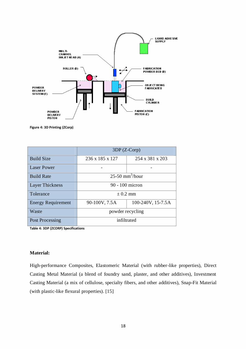
18
Figure 4: 3D Printing (ZCorp)
3DP (Z-Corp)
Build Size 236 x 185 x 127 254 x 381 x 203
Laser Power - -
Build Rate 25-50 mm3/hour
Layer Thickness 90 - 100 micron
Tolerance ± 0.2 mm
Energy Requirement 90-100V, 7.5A 100-240V, 15-7.5A
Waste powder recycling
Post Processing infiltrated
Table 4: 3DP (ZCORP) Specifications
Material:
High-performance Composites, Elastomeric Material (with rubber-like properties), Direct
Casting Metal Material (a blend of foundry sand, plaster, and other additives), Investment
Casting Material (a mix of cellulose, specialty fibers, and other additives), Snap-Fit Material
(with plastic-like flexural properties). [15]
19
Notes:
Support Structure is not necessary
Objet 3DP system:
The Objet 3D printing process is different from that of Z-Corp. The Eden Family of Objet
machines use jetting heads to lay the required amount of material, which are UV sensitive
photopolymers. Just as the materials are laid on the building table, the UV light head which is
integrated with other jetting heads cures the photopolymers. This means that laying and
curing processes are done almost simultaneously. The jetting heads and UV light move along
the 2D cross section of the object until one layer is done. Thereafter, the building tray will go
down in the size of a layer thickness and the next cross section will be built.
Both model material and support material are laid on the build tray and fully cured by the UV
light exposure. The support materials are removed by water jet after the object is completely
manufactured. Materials are not toxic. During the process, whenever the machine is about
running out of material, the material cartridges can be replace without any interruption in the
process and this provides better efficiency. The integration of the liquid material inkjets and
UV light head will provide better control of the material designation and alignment.
On the other hand, using UV technology and liquid photopolymers makes this method have
waste material because of the polymerization. So the cured material cannot be reused.
See Table 5 for specifications of the process. [18] [19] [20]
3DP (Objet)
Build Size 250x 250x 200 490*390*200
Laser Power -
Build Rate 20mm3/h
Layer Thickness 16/30 micron
Tolerance 0.1-0.3
Energy Requirement 110-240 V, 1.5 kW, single phase
Waste Irreversible process cause in in-recyclability
Post Processing Support removal
Table 5: 3DP (Objet) Specifications

20
Material:
Transparent material, Opaque material, rubber like flexible material, ABS-like,
polypropylene-like , rubber-like, High temperature resistance material, acrylic-based
polymer. [21]
2.2. Metal Methods
2.2.1. Direct Metal Laser Sintering (DMLS)
Process:
Direct Metal Laser Sintering (DMLS) is one of AM techniques for metals. The same process
of common AM methods happens here. In each step recoater, which is like a blade that
dispatches material powder, sweeps a layer of powder. This metal powder is sintered before
the build tray goes down in a defined size of layer thickness. Then the recoater dispatches
new layer of material, making the next layer to be sintered.
Along with layered manufacturing of part, support structure is also built depending on the
shape of product. The more complex the component is, the more economical is the technique.
Reduction in assembly time and increase in reliability by combining several parts and
manufacturing them in one go, elaborates the savings from this method. It also offers the
traceability by self labeling the products.
See Table 6 for specifications of the process. [22] [23]
DMLS
Build Size 250 x 250 x 215mm 250 x 250 x 325mm
Laser Power 200W 400W
Build Rate 2 - 4 mm3/s 2 – 8 mm
3/s
Layer Thickness 20 - 80 μm
Tolerance +/- 0.1 mm
Energy Requirement -
Waste 98% of unused powder is recycled
Post Processing support removal, shot peening,polishing, heat treating
Table 6: DMLS Specifications

21
Material:
Stainless Steel , Maraging Steel, Cobalt Chrome Alloy, Aluminium Alloy, Titanium Alloy
[24] [3]
Notes:
Multimaterial opportunity exist.
2.2.2. Selective Laser Melting (SLM)
Process:
Selective Laser Melting (SLM) is an AM method that uses high powered laser to melt
metallic powders together to shape the product from a 3D CAD data. Renishaw, the founder
of this technique, uses a high powered ytterbium fibre laser to fuse metal powders. the same
idea of AM happens. The recoater sweeps a layer of fine material powder and makes it ready
for the laser to fuse them according to the 2D cross section of each layer under a tightly
controlled inert atmosphere. When the part is made completely, it goes for the required heat
treatment and post processing.
Typical applications for laser melting technology are functional testing of production quality
prototypes, manufacturing of organic or highly complex geometries, low volume
manufacturing of complex metal parts in specialist materials.
See Table 7 for specifications of the process. [25] [26]
SLM
Build Size 125 x 125 x 125 mm 250 x 250 x 300 mm
Laser Power 100-200W 200-400W
Build Rate 4 - 16 mm3/s
Layer Thickness 20 – 100 µm
Tolerance +/- 0.05
Energy Requirement 230 V 1 PH, 16 A
Waste 95% of the material is re-usable after refinement
Post Processing -
Table 7: SLM Specifications

22
Material:
Stainless steel 316L and 17-4PH, H13 tool steel, aluminium Al-Si-12, titanium CP, Ti-6Al-
4V and Ti-6Al-7Nb, cobalt-chrome (ASTM75), inconel 718 and 625 [26] [25]
2.2.3. Electron Beam Melting (EBM)
Process:
Electron Beam Melting (EBM) technology builds fully dense parts from metal powder. The
metal powder is melted by an electron beam (power of up to 3kW) and so the technology
uses high energy to provide high melting capacity and productivity. Parts are free from
residual stresses and distortions. The required temperature is specific for different alloys, and
the electron beam maintains that temperature. Then for each layer, the beam melts contours
of the 2D shape of part and finally the balk; i.e. the surface area within the contours.
Building parts at elevated temperatures results in stress-relieved products with good material
properties. Also the process occurs in a vacuum space to maintain the chemical specification
of the powder material. Arcam, the owner of EBM patent, claims that their machines provide
parts with excellent properties for strength, elasticity, fatigue, chemical composition, and
microstructure.
See Table 8 for specifications of the process. [27]
EBM
Build Size 200x200x180 mm 200x200x350 mm
Laser Power 50–3000 W
Build Rate 45-66 mm3/s
Layer Thickness 50 micron
Tolerance +/- 0.2 mm
Energy Requirement 3 x 400 V, 32 A, 7kW
Waste 95% recovery of unmelted powder
Post Processing Support removal, Grit blasting
Table 8: EBM Specifications
23
Material:
Released Materials (which are basic common materials with detail defined properties by
Arcam Company):
Titanium Ti6Al4V
Titanium Ti6Al4V ELI
Titanium Grade 2
Cobalt-Chrome, ASTM F75
Additional Materials (which are not as specified as released materials, but have been used in
cases successfully)
Titanium aluminide
Inconel (625 & 718)
Stainless steel (e.g. 17-4)
Tool steel (e.g. H13)
Aluminium (e.g. 6061)
Hard metals (e.g. NiWC)
Copper (e.g. GRCop-84)
Beryllium (e.g. AlBeMet)
Amorphous metals
Niobium
Invar
[27]
Notes:
Comparatively to SLM and DMLS, EBM has a generally superior build rate because
of its higher energy density and scanning method. [27]

24
2.2.4. EasyCLAD
Process:
EasyCLAD uses a nozzle at which the metallic powders are injected and concentrated at
center end point of it where a laser beam is placed. The laser beam fuses the powder and
creates a dense and uniform deposite of metal. The process is protected by a neutral gas to
prevent oxidation. That makes the metallurgical properties of products good in comparison to
forging and casting.
Manufacturing functional parts, repair worn part, work on machined part, multi material with
powder mixing are the advantages of using this technology.
See Figure 5 for a schematic illustration of the method. [28]
Figure 5: EasyClad
EasyCLAD
Build Size 400 x 350 x 200 1500 x 800 x 800
Laser Power 300 - 500W 750 - 4000W
Build Rate up to 85 mm3/s
Layer Thickness 140 micron
Tolerance +/- 0.1-0.5
Energy Requirement 400VAC, 3phase , 17.3 kW
Waste Recycling of the powder
Post Processing polishing, blasting, micro shotpeening
Table 9: EasyClad Specifications

25
Material:
All kinds of metallic material can be atomized as powder grains. Like: TA6V, TiSn Alloy,
INCO 718, INCO 625, Stellite 6, 12, 21, 25, Tool Steel, Waspalloy, Hatfield steel, ... [28]
2.2.5. Laser Consolidation (LC)
Process:
Laser Consolidation (LC) uses a nozzle for its laser and a nozzle for material feed. This
technique requires a solid base (called substrate) to build the part on it. A consolidated laser
is used to creat a molten pool as the metallic powder is fed to it by the other nozzle at the
same time. The first layer is made creating a molten material as laser and powder injection
nozzle move along the cross section of the object. The molten material solidifies rapidly as
the nozzles move away.
Products manufactured by LC are fully dense and free from cracks as they are fully melted.
Good dimentional accuracy and mechanical properties are the benefits of using this
technology. [29]
See Figure 6 for a schematic illustration of the method. [30]
Figure 6: Laser Consolidation

26
Laser Consolidation
Build Size 500*500*500
Laser Power 20 to 300 W
Build Rate -
Layer Thickness -
Tolerance +/- 0.05
Energy Requirement -
Waste Using 99.5% of materials
Post Processing finishing
Table 10; Laser Consolidation Specifications
Material:
Laser Consolidation adds high strength alloy (super alloy) features or tool steel on
inexpensive metals, reduces expensive alloy use. [30]
Notes:
multimaterial possibility exist.
2.2.6. LaserCusing
Process:
The term LaserCusing comes from CONCEPT for the letter C and the word FUSING. It says
that the process uses fusion and complete melting to creat parts. The process is owned by
Concept-Laser Co.
The principle is familiar; a metal powder surface is dispatched over the build table. The laser
fuses the cross section of the required layer and the process repeats until the final product is
completed. Concept-Laser Co. clarifies that the special thing about LaserCusing machines is
the stochastic exposure strategy in line with the “island principle”. The segments of each
cross section in an individual layer are called “islands”. They are made in succession which
result in reduction in part’s inert stresses.

27
Products made by laserCUSING can be used as a finished high-quality industrial component
and for mass production tooling.
See Figure 7 for a schematic illustration of the method. [31] [32] [33]
Figure 7: LaserCusing
LaserCusing
Build Size 250*250*280
Laser Power 200
Build Rate 0.5 – 5.5 mm3/s
Layer Thickness 20 - 80 µm
Tolerance +/- 0.05
Energy Requirement 400VAC, 3phase, 22.1 kW
Waste 100% compatible for re-use
Post Processing Micro blasting
Table 11: LaserCusing Specifications

28
Material:
High-grade steels, Hot-work steels, Stainless hot-work steels, Aluminium alloys, Nickel-base
alloys, Titanium alloys, Pure titanium, Cobalt-chromium alloys, Precious-metal alloys. [31]
[32] [33]
2.2.7. Laser Engineered Net Shaping (LENS)
Process:
Laser Engineering Net Shaping (LENS) uses a high power (500W to 4kW) laser to fuse
powder metals and shape a dense product. It has a closed-loop process control to ensure the
accuracy of part manufacturing.
The metal powder is fed to the correct position over a substrate by means of one or more
feeders. The powder is deposited either by gravity or by pressure of an inert gas. The laser on
the other hand focuses a beam and creats a pool on the substrate or the previous layer. The
metal powder is absorbed into the molten pool. As the laser and powder feeder move along
the cross section of the object, the first layer is made. The whole process is done in a sealed
argon filled box to maintain the oxygen level in less than 10 parts per million (ppm) to have
the parts clean and prevent against oxidation.
The LENS technique has the possibility of using composite powder mixture. high
cooling/solidification rate is another advantage. On the other hand, severe overhangs are an
issue because of a lack of a different material for support structures.
See Figure 8 for a schematic illustration of the method. [34] [35] [36]

29
Figure 8: Laser Engineering Net Shaping
LENS
Build Size 300 x 300 x 300 900 x 1500 x 900
Laser Power 500W 1000W
Build Rate 5 mm3/s upto 60 mm3/s
Layer Thickness 120 micron
Tolerance ± 0.125 mm
Energy Requirement -
Waste 80% powder utilization
Post Processing -
Table 12: LENS Specifications
Material:
variety of metals including titanium, nickel-base super alloys, cobalt, Inconel, stainless steels
and tool steels. [34] [35]
30
Notes:
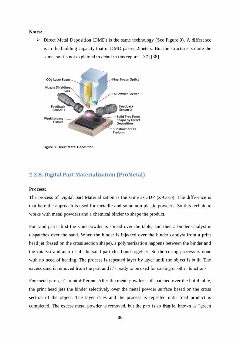
Direct Metal Deposition (DMD) is the same technology (See Figure 9). A difference
is in the building capacity that in DMD passes 2meters. But the structure is quite the
same, so it’s not explained in detail in this report. [37] [38]
Figure 9: Direct Metal Deposition
2.2.8. Digital Part Materialization (ProMetal)
Process:
The process of Digital part Materialization is the same as 3DP (Z-Corp). The difference is
that here the approach is used for metallic and some non-plastic powders. So this technique
works with metal powders and a chemical binder to shape the product.
For sand parts, first the sand powder is spread over the table, and then a binder catalyst is
dispatches over the sand. When the binder is injected over the binder catalyst from a print
head jet (based on the cross section shape), a polymerization happens between the binder and
the catalyst and as a result the sand particles bond together. So the curing process is done
with no need of heating. The process is repeated layer by layer until the object is built. The
excess sand is removed from the part and it’s ready to be used for casting or other functions.
For metal parts, it’s a bit different. After the metal powder is dispatched over the build table,
the print head jets the binder selectively over the metal powder surface based on the cross
section of the object. The layer dries and the process is repeated until final product is
completed. The excess metal powder is removed, but the part is so fragile, known as “green
31
state”. It should go for a sintering process where the binder is burned and metal particles are
melted and hardened. It gets 60% dense and it usually goes for an infiltration process to get
full density.
For glass parts, the process is the same as metal parts, but it doesn’t need the infiltration
process.
Less waste and patternless sand casting possibilities together with the possibility of complex
internal geometry availability are the benefits of this method. However, the time consuming
post processing (specially for the metal and glass parts) are the weaknesses of it.
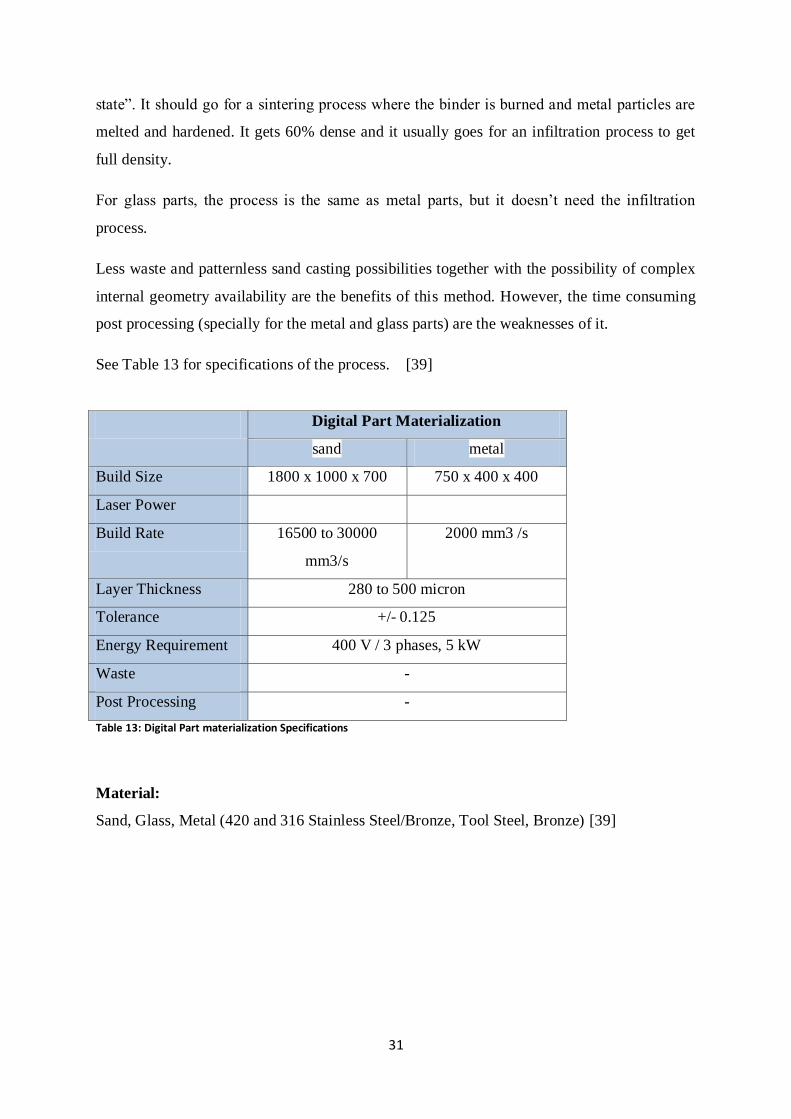
See Table 13 for specifications of the process. [39]
Digital Part Materialization
sand metal
Build Size 1800 x 1000 x 700 750 x 400 x 400
Laser Power
Build Rate 16500 to 30000
mm3/s
2000 mm3 /s
Layer Thickness 280 to 500 micron
Tolerance +/- 0.125
Energy Requirement 400 V / 3 phases, 5 kW
Waste -
Post Processing -
Table 13: Digital Part materialization Specifications
Material:
Sand, Glass, Metal (420 and 316 Stainless Steel/Bronze, Tool Steel, Bronze) [39]
32
2.2.9. Other Methods
There are number of other methods and there are new ones generating. Although the concept
is the same, but they combine different technologies and generate different part specifications
as a result.
Some other methods are Ultrasonic Consolidation (UC) which is based on ultrasonic
welding of the metal foils. This is one of the hybrid technologies that combine additive and
subtractive methods by joining metal sheets and contour milling respectively. Ultrasonic
oscilation together with pressure welds the metal sheets, and then a CNC mill will shape the
required countor of cross section. Foils of Al-Cu alloy, Ni-base alloy, Inconel, Al alloy can
be used for this method. [40] [41]
Another method is Ion Fusion Formation (IFF) which is DMD-like process but it uses a
plasma welding torch that generates very hot ionized gas to melt the deposited metal. One
advantage of this method has been recognized as the possibility of having coating application
in build process. [42]
The Laminated Object Manufacturing (LOM) from Helisys Inc. and many other methods are
developed and under development. But in this project has not concentrated on them.

33
3. Capabilities and Opportunities
3.1. Overview
Additive Manufacturing has been used initially for prototyping. In fact it was the first and
successful area of application for AM which made it categorized in Rapid Prototyping
concept. Prototypes which were used for visual understanding or presentation models were
later used for testing operations also, and current application of this technology is heading
more and more towards part production, besides prototyping.
The main barriers, which are challenges that prevent AM to be used for part manufacturing
widely or vast its market, are:
- material,
- cost (of production due to materials, machines…) and
- surface roughness and accuracy
There are a lot of concerns about material improvements (e.g. in Loughborough University)
and the range of materials which could be used for AM is growing. But it is still a challenge.
While there is opportunity for new kind of materials, mixture of materials (for instance in
EasyClad and Laser Consolidation Technologies) and better microstructures of materials,
there exist problems concerning material tolerability in terms of weight, temperature and
force. However, every year there are a new group of materials introduced for AM and
refinements of the properties. A concern in this area is to create a standard for material.
Standard material will later allow for Finite Element Method (FEM) which is a part of
Product Lifecycle where virtual tests are executed. Standard material will also make the end

34
user trust the product built by AM method. ASTM International prepares two meetings per
year to review the progress of this standard establishment.
The cost of producing parts is high if AM is used for large quantity of products, at least by
now. With better materials, faster machines this problem can be solved or mitigated. This
technology works better than conventional methods if a small batch is going to be produced.
Because the cost of making a one off product with conventional machines will need tooling
which is the main cost, AM can take this responsibility since it does not need tooling thanks
to its layer by layer manufacturing method. It also beats traditional manufacturing methods
when the part geometry is complex or even impossible to build with classical techniques. But
when it is a mass production, the cost of tooling becomes inconsiderable. However it is
assumed [43] that with the market going toward customization and more innovative products
with shorter life cycle, and with less RM labour cost this problem may become less than an
issue in future. [44]
An issue of the AM techniques is surface roughness and accuracy that is not sufficient for
part production unless some kind of post-processing is added to the manufacturing chain
(sanding, pinning… or even machining). However some companies like EOS claims that
customers can use the product after simply a shot pinning process. But generally, the need to
have some finishing processes after making the product by AM, will result in an increase in
cycle time and cost. But hybrid machines can solve the problem. As an example the Japanese
Matsuura LUMEX Avance 25 which combines metal sintering with subtractive milling
process after every single layer if needed, was introduced at Euromold 2011 (an event related
to AM techniques). This machine gets benefits of machining accuracy and surface roughness
and flexibility of additive manufacturing. [45]
These three main challenges which AM technology is facing will become solved with better
machines with faster and more accurate lasers which combining with better material can
overcome the current problems and barriers. Despite, producing end use products (considered
to be the largest application of AM in future) is more challenging than just prototyping
(Figure 10). So it surely takes time to become fully accepted in industry as a new generation
of production. [46]
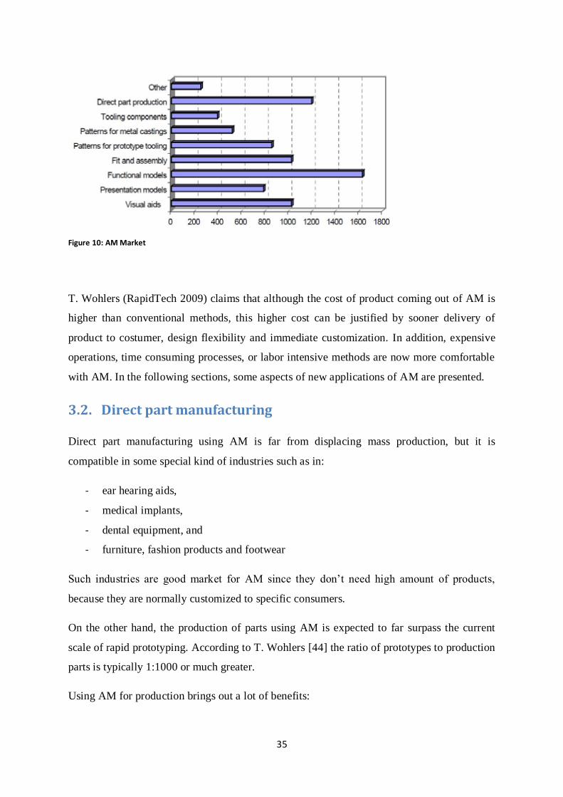
35
Figure 10: AM Market
T. Wohlers (RapidTech 2009) claims that although the cost of product coming out of AM is
higher than conventional methods, this higher cost can be justified by sooner delivery of
product to costumer, design flexibility and immediate customization. In addition, expensive
operations, time consuming processes, or labor intensive methods are now more comfortable
with AM. In the following sections, some aspects of new applications of AM are presented.
3.2. Direct part manufacturing
Direct part manufacturing using AM is far from displacing mass production, but it is
compatible in some special kind of industries such as in:
- ear hearing aids,
- medical implants,
- dental equipment, and
- furniture, fashion products and footwear
Such industries are good market for AM since they don’t need high amount of products,
because they are normally customized to specific consumers.
On the other hand, the production of parts using AM is expected to far surpass the current
scale of rapid prototyping. According to T. Wohlers [44] the ratio of prototypes to production
parts is typically 1:1000 or much greater.
Using AM for production brings out a lot of benefits:
36
- Part consolidation
- Reduction/elimination of tooling
Part consolidation reduces assembly, tooling, inventory, waste and inspection costs with
AM’s high flexibility in geometric complexity design which defines the main advantages of
direct part manufacturing. Part consolidation will also increase the opportunity of making
more complex parts while Reduction in assembly and sub assembly means less labor and less
cycle time.
Reduction of tooling eliminates the design considerations and economics of part
manufacturing which are the restrictions of conventional production. So the possibility of
design will become restricted only to design tool (CAD) limitations.
However, having AM as part production methods brings out new aspects for designers, like
considering:
- minimum wall thickness,
- achievable tolerances and
- preferred build orientation.
They can also think “outside of the box” because of new design freedom.
To have AM as production system one must also consider build speed and capacity in
conjunction with machine price. To have AM more viable in production area, these aspects
should be improved. [44]
3.2.1. Consumer products
In the area of consumer products, furniture, lightning, office accessories, fashion products,
jewellery, art and gifts are in attention of AM market.
Consumer related AM brings out the opportunity for consumers to design their own desired
products or to buy custom and edited products, and designers to quickly step in market after
making their prototypes.
Currently there are some opportunities regarding online ordering for parts from customers.
They will define their products using a CAD system. Some user-friendly design support tools
are developed, e.g. Google SketchUp, FreeForm from Sensable, and Spore Creature Creator
37
from Electronic Arts. But this option is most comfortable for industry levels. Using a CAD
system needs training and not all the people are used to work with such systems.
A number of user-friendly design support tools have been developed but there is no guarantee
that the designed shape would be produced. On the other hand if the product is going to be so
complex, then it may need professionals to design it because they have lots of internal parts
and need engineering ability to make them. Some design toolkits, however rare, but exist. For
example Rapid Shell Modeling software for hearing aid design from Materialise have
capabilities like automatic placement of components, interactive previews, and automatic
quality checks and use a model either coming from a consumer or from a 3D scanner.
Examples are consumer designed products are pasta boxes (by Billy Zelsnack) and
headphone wrappers (by Eric Weinhoffer) which are ordered by consumers who designed
them for their everyday comfort. Development of comfortable and easy-to-use 3D modelling
systems could turn two billion Internet users into potential AM customers in this way.
People can also buy the customized products with some modification and edition options.
FigurePrints company makes the avatars from game characters and have gained a good
market in this area so that customers can have their orders of avatars in colors. FigurePrints
gets the data information of avatars which are normally stored in 3D file format in games, to
produce the products by 3D printing.
A big potential users of AM machines are new entrepreneurs who have innovative ideas in
mind and want to show up in market. These people are mostly concerned about the viability
of the material and the surface finish that the system provides for them. They will buy an AM
machine when they get sure that the machine will represent what they want so that they can
quickly get into market. So depending on their product complexity, material and required
accuracy they decide to work with what kind of machine. Wider range of material or lower
cost of machine or improvement in machine features will vast this market.
Another challenge in this area is that consumer products using AM machines are limited to be
small due to the small production volume and cost of production that this technique has by
now. [44]

38
3.2.2. Industrial Products
Here some examples of use of AM part production in some industries are represented:
Aerospace: several parts for satellites are made by AM methods like laser sintering.
LENS technique’s most common application is for direct part manufacturing for
Aerospace.
Automotive industry: many assemblies such as audio/video assembly or headrest
assembly and engine control units are made by companies that use AM.
Machinery industry: reduction in weight is in consideration. Using light weight
material by AM to produce drag chain links for mining industry is an example.
Medical industry: custom-made products in is often a necessity; e.g. cranial plates,
artificial jaws.
Manufacturing industry: jigs and fixtures, templates, gauges, drill guides are types of
manufacturing tools which are normally expensive because they are customized and
are produced in a small number of items. In this area, AM has gained a good attention
and is successful in that. [44]
3.2.3. Tooling
A big market that AM has started as its initiation for direct part manufacturing is tooling.
Currently many methods such as DMLS, SLS, SLM, EBM, ProMetal, LENS, DMD, and UC
are commercially available for direct tooling and metal parts. In addition to jigs, fixtures and
gauges, another area is tooling such as dies and patterns for casting. For example, almost any
type of AM methods can produce patterns for investment castings. For complex shapes, AM
patterns bring out a huge saving in time and cost in comparison to machining. According to
research the number of companies which adapted their systems to use AM patterns for
casting had an increase from 5% to 95% in the last decade.
There are two categories of using AM in tooling:
- Indirect approach: includes patterns which are used to make dies and molds (master
patterns).
- Direct approach: directly producing inserts and dies.
39
AM is also capable of producing cores in casting which are inserts for undercut features.
These are like patterns’ indirect assist in tooling. Patterns used in silicon rubber tooling,
epoxy-based composite tooling, spray metal tooling and many other methods are usually
made by AM.
For direct tooling approach, EOS, ProMetal, 3D Systems, and ZCorp have offered systems
that are capable of creating molds directly. However they haven’t gone through sand casting
except ProMetal. Also POM and EOS systems produce dies for die casting, but because of
required pressure and temperature in die casting, it seems improbable that AM will replace
machined tooling in this area in the near future unless a new generation of materials is
developed for.
One advantage of using AM for direct tooling is that it will reduce the number of steps
required to make the tooling; i.e. to produce dies directly will reduce the time of creating
molds and dies because there is no need of making pattern. It also increases geometric
inaccuracy compared to pattern-based process.
Another advantage of using AM for tooling in dies is that because of its rougher surface in
comparison to machined parts, it’s better for cooling systems in dies. The rougher surface in
cooling channels increases the heat transfer which is called conformal cooling.
On the other hand, Optomec and POM have used AM to produce direct molds and dies with
copper cores. Copper is highly thermally conductive and so it better transfers out the heat.
The outer side is made of thermally resistant hard material. Thus it’s good to construct dies in
this way for a better thermal management.
The strength and weaknesses of conventional machining such as CNC machines and AM
machines for tooling should be considered for any case. It should be decided based on
complexity, surface quality, allowed design changes, material and time to market.
Sometimes maybe a hybrid solution is useful, when inserts can be produced by AM and the
other parts with CNC machines. In this way we can take advantage of both systems. For
example a most common way of using hybrid system is to use DMLS for production of cores
and using CNC for cavity part. However in this case also a challenge is the incompatibility of
the tolerance of two systems, normally the accuracy of AM machines are not the same as
conventional machining. Also material properties used by two systems differ (which clarifies

40
the need for standardization). So, one should consider this in the design of the hybrid system.
[44]
3.3 Rapid Manufacturing
A widely accepted definition for Rapid Manufacturing (RM) is generated by Neil Hopkinson
at Loughborough University. He defined it as “The use of a CAD-based automated additive
manufacturing process to construct parts that are used directly as finished products or
components”. Therefore, as it is mentioned in the previous subchapter, producing consumer
products, tooling, or industrial products are all included in the RM area, if they are produced
directly from an AM method. [47]
RM has been considered as one of the most exciting methods for 21th century which is
progressing fast. The wide range of market that it covers consist of aerospace, automotive,
medical, healthcare and consumer products such as furniture and shoes.
Despite all the examples provided before, there is still more progress and development to be
done for RM to be used widespread.
3.3.1. Design freedom
The major driver for using RM is in design area since it offers the capacity of producing parts
with unlimited geometry complexity. Conventional manufacturing’s cost is highly dependent
to the geometry complexity. RM however is not only independent to complexity, but also is
capable of production of every shape.
Lower cost combined with design freedom will benefit both manufacturer and customer
which mean better customer satisfaction.
Currently, designers should be well familiar with the design constraints and geometry
feasibility considering all the production steps (manufacturing but also assembly,
maintenance, disposal…), which is called Design for Manufacturing and Assembly (DFMA).
DFMA puts a step before designing level, at which manufacturing requirements and
constraints are represented to designer so that he can design the required product in a way
that it won’t be hard to manufacture. But with the help of RM the only limitation is the
designer’s imagination and the design tools. So Design-for-Manufacturing is shifted to
Manufacturing-for-Design using RM.

41
The impact of RM on DFMA is so wide because it doesn’t need tooling, e.g. injection molds
and thus will remove the barriers such as wall thickness limitations, sharp corner avoidance,
need for ejection pins.
In addition, RM will make it possible to create features which are not possible by
conventional method or it requires high-cost tooling complexities and set ups. These features
include blind holes and undercuts.
Moreover, there is no necessity of considering split lines especially in comparison to injection
molding which needs experience to place such features and sometimes it is not possible.
RM will hide the constraints of Design for Assembly in the area at which it reduces the
number of parts which are going to be assembles. In other words it is able to manufacture
sub-parts consolidated in only one part. It also reduces the time of assembly by integrating
assembly process with sub-products’ production.
3.3.2. Mass Customization
The less the batch size, the more effective is RM. Although the range of batch size is
increasing year by year, but still in comparison to conventional systems, RM is well serving
products of one or few but with high details and high profit per product unit. Using
Conventional methods for production in low volume will require a high cost of tooling, set
up, etc. But if RM is used for such end use products, then it will be more efficient to produce.
An era, in which RM has taken place in some companies, is body fitting products. Especially
in car manufacturing, this area has been under consideration, but it was so expensive because
of labour cost and tool cost since products should be configured for each customer and it will
make different product, in this case car seats, from customer to customer. So, highly mass-
individualized products cannot be produced conveniently with non-additive methods. These
boundaries made such products far from public eye because they were considered as highly
customized and expensive products. But with the help of RM producing such products which
are ergonomically friendly with body can be widely provided. Mass customization is decided
to be done in automotive industry, car seats, for MG Rover Group. [47]

42
3.3.3. Added functionality
Additional functionality in a product will help it to be more advantageous in use. Including
porosity in parts produced for medical implants to improve cell-ingress possibility or have
porous parts to have less weight are some examples of added functionality. RM with its
additive layer technology can make it possible.
One market sector which is so capable of using RM but is not conquered so much is textile.
With the help of this technique new styles of garments can be produced which are innovative
both in texture and garment body fitting structures. This will lead to have more functional
garments. However there are some problems in using the new method for this area. Some
problems include RM systems’ resolution and 3D data generation incapability.
Loughborough University has used SLS technology to make fabrics however. But still there
should be more investigations on smart textile production. [47]
The on-going potential includes multiple weaving, assembled garments, textiles with built in
functionalities.
3.3.4. Process improvements
RM provides the opportunity of having distributed manufacturing. This possibility will let the
manufacturer to make the product more near to customer, so that the packaging,
transportation, and lead time will be decreased thanks to the decentralization of the
production system.
An example in this area is the pierce of RM in game industry where the customer is widely
distributed. Customer will order the character of the game that he wants and manufacturer
can produce the same product in multiple locations being protected from the single source
production system. In single source production the company will face a lot of investment
having same tooling and instrument in different places; but since RM does not require any
tooling, it is free from such a risk.
Another thing to be mentioned is that the need for a huge initial investment most of the times
prevents new products to enter the market. With the help of RM there is no need of
consideration for tooling or moulds. In other words, it not only removes the need for tooling,

43
but also eliminates the need for tooling companies, i.e. die makers, moulding creators, cutting
tool producers, etc. this will make this technology a disruptive system for other methods. [48]
3.3.5. Environmental drivers
RM normally uses less energy than conventional systems such as heavy presses, injection
motors and melting systems. This less energy usage make this method of manufacturing
competitive since these days there is always speaking about energy limitations.
Another area at which RM can benefit is waste. It is obvious that RM produce less, if any,
waste because it uses additive methods instead of subtractive methods. The ration of input
material to output product material usage is so high in machining processes. Although in
some methods there exists waste generation in terms of support material and used powder,
many other methods are more than 95% material efficient in terms of reusability or
recyclability.
As it is mentioned previously, distributed manufacturing will result in less packaging and
transportation which will be translated to less haulage. This makes this method to a more
environmentally friendly method since the cost of fuel and natural resources is increasing.
As it’s discussed on better functionality of the products manufactured by RM, another
advantage is gained which is defined as the term optimized product. An optimized product
can be lower weight product or better featured product. Either way it will result in reduction
of energy and natural resources consumption. [48]
44
4. Rapid Manufacturing in Supply Chain
4.1. RM Overview
Rapid Manufacturing (RM), as it is defined before is a method to use Additive Manufacturing
(AM) for end use products. But RM is not the only application of AM (sometimes called
Additive Layer Manufacturing processes). Another application is for prototyping.
As it’s mentioned in chapter 3 the initial concept of RM started from Rapid Prototyping (RP).
In RP, the purpose is to quickly make, to use as a conceptual model, test the functionality or
any other processes that include first released product evaluations. For prototypes which are
going to be used as a sample part or to test a function, it is not economical to put cost on
making moulds or manufacture it with common methods of manufacturing. These methods
are not economical, but RP not only saves money to build a testing part, but also makes it
possible to make any part with any design. In addition RP does not only use AM, it may also
use other rapid methods such as High Speed Milling.
The main advantage of RP is its ability for one-off jobbing. It is expensive to manufacture
and set-up traditional production tooling and moulds to produce a prototype, especially if it is
revealed that the proposed product is not functional and needs redesign, it becomes a high
risk investment. By means of RP the problem of time and money wastage can be mitigated
considerably. However some prototypes do not have the accuracy or functionality of end use
appliance. It of course depends on the desired accuracy and requirements of product.
While the advantages of RP were taking place in production units, another concept started to
appear: Additive Manufacturing. It uses 3D CAD models as an input and produces the
product layer by layer. So AM is included in RP, but it is not the same, since RP does not

45
necessarily use layered techniques. In practice, however, the term Rapid Prototyping has been
traditionally used to refer to prototyping using AM techniques although that is currently
changing in the direction of clearly differentiating the terms RP and AM.
AM is generally suitable for production of functional end use parts in small
volumes/quantitites, as mentioned in chapter 3; but it is just a technique, and a technique can
be used either in design of experimental models, or in end-use product manufacturing. This
means that one application of the AM is in prototyping, namely Rapid Prototyping, while the
other application of it is in production line, namely Rapid Manufacturing.
RM is the application of AM in fabrication, so it shapes the system of production based on
Additive Layer Manufacturing. This is the maturity of this concept up to now and it is
growing more and more to take place in many industries; aerospace, health, casting, etc. the
application of it has been discussed in subchapter 3.2.
The main advantages of RM, is that it directly makes the product from a 3D data model with
additive methods and their advantages (regarding to material waste, flexibility, speed….). So
if the advantages can become compatible to production systems and disadvantages become
solved by supporting methods, then what will be the barrier for its application? Of course
everything depends on product type and required features. Sometimes RM doesn’t offer
required product lifetime and sometimes it doesn’t bring out the required accuracy. There
should always be evaluation of pros and cons, product by product.
4.2. Supply Chain Principles
A supply chain starts from raw material supplier to customer and involves all the people and
machines with information and activities among them. To explain the concept regarding
managing of the chain of production, the following concepts are explained.
Lean Concept in production:
Lean production is defined as “an adoption of mass production in which workers and work
cells are made more flexible and efficient by adopting methods that reduce waste in all
forms”. [49] Hobbs [50] mentions the production of the “one unit at a time” to eliminate
delays such as queue time in lean concept. The reduction of waste in time, space and cost
with better configuration of the man-machine system and resource designation is the main
46
issue in a lean production system. However it is also related to concepts like pull systems,
less WIP (work in process), Just in time production methodology and flexible manufacturing.
In a pull system the production is based on actual demand. Whenever an order is received, the
production line (or part of production line) starts manufacturing based on that order. It stands
against the push system in which the production is based on forecasted demand and products
are pushed forward in the supply chain. In a supply chain normally both behaviours can be
found. The interface between the stages where push system is replaced by pull system is
called “decoupling point” [51].
Work-In-Process is a term devoted to unfinished products which are either under fabrication
or in waiting queue. In lean concept it is important to have an eye over the WIP, because it is
a type of waste in time if the products are waiting in a queue to be processed. In fact it is
none-value-adding [51].
Just-In-Time (JIT) is a set of principles, tools and techniques that allow a company to
produce and deliver products in small quantities with short lead times, to meet specific
customer needs [52]. Producing in small quantity batches will result in less buffers and
smoother production line. JIT also tries to have less waste but with shorter lead time. Every
stage should produce the right amount at the right time, so that finally they can meet the
desired lead time [51]. It uses pull system to produce the required amount at the required
time. So it needs an accurate forecast.
Flexible manufacturing is a system at which there is a capability of reaction and adoption to
some wanted or unwanted changes. Such a system can save a lot to time, cost and energy,
especially for highly variable or customizable products.
Overall, Lean production has the goal of less waste and it uses pull system with one-unit at a
time strategy to have a smooth flow [51]. The lean supply chain users should also be able to
predict the demand in a way that helps them to produce the required amount in the required
time and to keep WIP low and to smooth level of scheduling. They should also keep this
levelled scheduling with their suppliers since they are also part of the chain.
Agile Concept in production:
An Agile production system has the ability to react quickly in demand flexibility in volume
and variety [53]. So in situations where the demand uncertainty is high, agility looks to be a
47
good strategy and as an agile system, one can gain advantage of better customer satisfaction
and an increase in market share. Agile manufacturing also comes along with make-to-order
strategy with flexible manufacturing to act fast in case of change in demand [51]. Cycle time
is a term that one should control and decrease if possible, for faster reaction in agile
methodology.
Predicting the demand to have a better responsiveness is a key in agile manufacturing. Here
because of volatility in demand in case of volume and variety, the mass customization is a
characteristic of agile supply chain and also keeping safety stock (to prevent lack of
inventory) is common for the same reason [51].
Leagile Concept in production:
The definition of Leagility is “the combination of the lean and agile paradigm within a total
supply chain strategy by positioning the decoupling point so as to best suit the need for
responding to a volatile demand downstream yet providing level scheduling upstream from
the decoupling point” [54]. Naylor also defined the decoupling point as a separator of the
customer-order-oriented part from planning-oriented part of the system.
The purpose of having a lean supply chain is to identify and eliminate the waste in the whole
chain to have an efficient chain. Normally such a supply chain is for functional products
while in agile supply chain the organization is looking for responsiveness in an innovative-
product market. Both lean and agile supply chains attempt to reduce non-value adding
processes, but stock allocation is included in agile manufacturing since it needs to react on
fluctuating demand. In agile type of production chain, normally the life cycle of the products
are lower than that of the lean style supply chain. So in lean concept products and also
processes are more standardized while agile processes have to be more reconfigurable [51].
Leagile strategy tries to take advantage of both lean and agile manufacturing. It has to define
the decoupling point at a stage where the lean concept changes to agile production [51].
4.3. Why RM can contribute in supply chain principals?
Rapid Manufacturing is used to produce products directly using, mainly, AM methods. So it
sure has impacts on supply chain. In fact it will remove some stages and units. The influence
of RM on supply chain clarifies the need for adoption of it to the current system, weather it is
a Lean, Agile, or Leagile based system.
48
In lean manufacturing:
If in a supply chain, the dominant paradigm is lean production, then it means that the
system’s goal is to produce by means of fewer resources with concentration on waste
elimination.
Less waste can be achieved by RM system. As it is discussed on environmental aspects of
RM in subchapter 3.3.5 it has advantage of using less waste production methods since they
are additive methods rather than subtractive methods. So the less waste can help RM to be
better adopted by lean supply chains. However, waste is not just about material as it is
mentioned in subchapter 3.3.5, some AM techniques use less energy rather than traditional
methods (injection motors and melting tools).
Using RM needs less chain of production units, because the input is a 3D model and it
directly generates the part from the computer designed model. There may be some stages for
material support and post processing units, but still it may result in less required production
space and maybe less production equipment rather than conventional methods which need
different stages of manufacturing. RM usually eliminates some stages of assemblies. Part
consolidation is one of its capabilities that it can produce the product as it’s assembled, so it
doesn’t need to produce sub-products and then assemble them together. It also provides
means of manufacturing parts that weren’t feasible with traditional methods (i.e. subtractive
methods). Conventional methods also need set-up times and positioning for each step of
manufacturing. This is what bolds the RM methods in time reduction. This time which is
spent for set-ups is not value adding time, so there will be less waste time.
The other aspect in which RM transcends in lean manufacturing is less human effort. It is true
that it requires CAD modelling expertism to design the part (although due to its virtually
shape-free design dependency, the designer do not really need to know much about HOW
her/his part is going to be manufactured to decide a certain design or assembly), but after that
there is no need of labour in manufacturing stages. As a matter of fact, the manufacturing
stages don’t need highly specialized human expertise.
What should not be underestimated is that in lean, which is based on less waste production,
the non-value adding operations should be eliminated as much as possible. The best example
of non-value adding operation in any company is transportation. The transportation of
unfinished products between stages, can be eliminated or at least decreased by RM, because it
49
requires less stages for manufacturing parts. Also nowadays companies are trying to move the
production more near to market so that the transportation to the customer from the last stage
of production will become less. RM can be very helpful in this concept as it is mentioned in
subchapter 3.3.4. There it is explained that it can help to decentralize the production and
bring out the possibility of a distributed manufacturing. The result of having such
manufacturing system is to have less transportation, less packaging process and less delivery
time.
Cox [55]mentions reducing the number of suppliers as a characteristic of a lean paradigm. In
RM, the number of suppliers is limited to material in form of powder (i.e. SLS, SLM), thread
(FDM) or liquid (i.e. SLA, 3DP-Objet) provider and 3D data generator (if the design stage is
not included in company itself).
In the concept of Just In Time (JIT) which is hidden in lean manufacturing, RM can take part
because it is a good method for fast and small quantity production, which is key in JIT as it is
defined before in subchapter 4.2. RM leads to JIT from the first stage of manufacturing. So it
implements JIT in the first steps of production. Less stocking and less WIP is gained from
RM as its only resource is material and 3D data model.
In agile manufacturing:
In agile manufacturing the concentration is more on lead time reduction. In agile concept,
system is supposed to respond fast in demand changes, whether it is volume change or
product change. In each of them, implementation of RM can be an assist.
If the agile supply chain is facing a change in demand variety (change in product and feature
adjustment), it needs a reconfigurable systems to become adapted to the new situation.
Otherwise it will lose the customer because of less customer satisfaction. RM welcomes
changes in product configuration and this change should just affect the 3D data model which
is behind manufacturing stage. In other words it doesn’t need a change in jigs, fixtures,
machine setups, etc. these are all what should be considered in conventional methods, and
they are not an issue for RM systems.
If agile supply chain is facing a change in demand volume, RM can help to still keep the
delivery time short. Normally it reduces the delivery time because of the opportunity of
distributed manufacturing which helps to shift the production more close to customer. But
also in case of demand variation, which is normal in agile supply chain, this method helps to

50
deliver the unpredicted orders thanks to its Rapid techniques. However, as it is mentioned
before, RM is not still capable and efficient enough to produce high volume batches.
A considerable issue in agile supply chain is the mass customization. The concept of mass
customization is included in agile manufacturing, because the demand is volatile. So products
normally are normally different and in many kinds, which mean that they are specialized,
individualized or as an engineering term, customized based on customers’ requirements. The
power of customer is forcing companies to pay more attention to customer satisfaction and so
each customer is ordering a product that answers his or her needs well. RM well serves the
customization. The more customized and the less volume is the market, the more efficient is
the RM. So RM serves mass customization in a good and advantageous manner.
In leagile manufacturing:
In general, less waste, better flexibility, re-configurability, fast customization compatibility,
reduction in stock level and WIP, makes RM to be able to provide a leagile supply chain.
Leagility makes it possible to take advantage of both lean and agile and as discussed above
RM has compatibility to both concepts.
In some industries (specialized products, like body fitting products) the production is
triggered when a customer order is received. This is a pure pull system and is applied in
industries at which company involves the customer in the first phase of production which is
normally part design. Pull system helps to produce exactly what is required in the required
amount (lean) and if the market is volatile then the variety of products forces to have a
flexible production system to act fast regarding order (agile).
Considering all the facts above, RM has a profound effect and compatibility to lean, agile and
leagile chains. But one should keep it in mind that still it is not an efficient system if the
production volume of each customized product is high.

51
5. Application Cases, Cost Analysis and Discussion
5.1. Overview
Among all the characteristics that differentiate products from each other, the ones preliminary
considered are:
- Product lifecycle: the time frame from initial concept until it becomes obsolescent.
- Part revenue: the amount of money obtained from selling a product.
- Production volume size: whether it is small scale or mass production system.
- Material: the part can be made of one or more than one material.
- Number of assembly stages: normally AM can work independent of required
assembly level. In fact, it can produce parts in single step by eliminating assembly
stages (part consolidation), while subtractive manufacturing methods may need
different stages for the same part to assemble sub-components of it.
- Size of product: this is considered a limitation for RM. If the size of the product is
beyond the built size limits of AM techniques then one should think about part
division or use other techniques (smallest feature size is about 0.01inch=0.25mm for
AM techniques, and the normal maximum build size is approximately 550*550 for X-
Y direction and exceeds to 750 for Z direction, like SLS. But some methods – SLA,
LENS, DMD and EasyClad - can produce in larger parts)1.
1 Materialise Mamoth SLA machine has the build size of more than 2 meters (http://manufacturing.materialise.com/mammoth-stereolithography-0), while Nanoscribe 3D laser lithography can produce in nanoscales (http://www.amsterdamnanocenter.nl/amsterdamnanocenter/equipment-info/nanoscribe/)

52
- Color: while the possibility of production in different colors exist (e.g. ZCorp 3DP
method), other techniques of AM are not able to color the product during the
manufacturing.
- Type of product: in terms of being single part with single material, single part with
more than one material, mechanisms with one material, or mechanisms with more
than one material.
- Mechanical properties: the product must satisfy the desirable requirements, for
example density.
- Design complexity: AM allows for a freedom in design without being concerned
about implementation constraints regarding design for manufacturing criteria.
One should consider all the affecting criteria to analyze the method of production, but in this
thesis the examples are categorized in a selection of mentioned criteria to show the
specification of each market sector. Meanwhile the benefits and limitations that RM will
provide are explained for each case.
Finally an analysis on cost of production is done. The goal is to see the influence of different
parameters that generate the total fee of a part. As it is mentioned before, AM eliminates the
tooling cost and reduces the number of work stations and as a result labours. Instead, other
variables show up such as support material effects.
For a simple general cost analysis of methods and examples, the upcoming formula is used.
In this formula:
- 30 percent of the material which is not fused is considered as scrap,
- finishing time for each batch of production is assumed as 2 hours,
- labor cost is supposed to be 500 SEK per hour,
- 30 percent of all other cost is added as overhead cost
- for each part, an approximate of 0.5 centimeter is considered to be added to the actual part’s
envelope height, for the material build tray altitude. This 0.5 cm is for assurance of having
enough powder to be fused,
- the investment – which is the machine cost – is considered to be returned in 4 years.

53
(Other parameters such as part volume or machine price, are dependent on the product and
technique.)
Total Cost per Part = (Material Cost + Depreciation Cost + Labor Cost) * (100+overhead
percentage)/100
In which:
Part Material Cost = (Part Volume + Support Volume + Scrap Volume) * Material Cost
Scrap Volume per Part = {assumed percentage of scrap * [machine build envelope size –
number of products in one batch*(part volume + support volume)]} / number of parts in one
batch
Depreciation Cost = (part volume + support volume) * machine cost / (Return on Investment
* yearly working hours * Machine Build Rate)
Labor Cost = (finishing time for each batch / number of parts in one batch)*hourly labour
cost
(For exact formula please check the excel file in Appendix A)

54
5.2. Application Case 1: Medical Implant Industry (Jaw Implant)2
Life cycle Medium
Part revenue High
Production volume size Small
Material Titanium, polyethylene, strengthened
ceramics, natural bone3
Table 14: Medical Implant Market Sector
http://www.materialise.co.kr www.theblaze.com
www.gizmag.com www.3dsystems.com
Figure 11: Medical Implants Examples
Best examples of this classification are implants; jaw implants, dental implants, skull
implants, body-fitting implants (body implants are more complex in terms of material: they
usually contain different materials for different sections).
2 http://old.materialise.com/materialise/view/de/1292006-Successful+jaw+implant+surgery.html 3 artificial bone made of strengthened ceramic by silica and zinc. Growth of natural bone around an
artificial scaffold (http://www.3dprintingnews.co.uk)
55
In general, a medical implant has a short life cycle which means that changes and innovation
is high in that market and new needs are defined for each case. Its profit is high and its
necessity and on-demand feature makes it a high revenue product. Patients are willing to pay
for a better implant in their body since it is related to their health. The production volume size
for implant is not high as a result of customization.
The material should be durable and bio-compatible. The main material which is used
normally to make a jaw implant is titanium. Other used materials are silicic implants,
polyethylene implants, bio-ceramics (for hard tissue implants), Cobalt-Chrome alloy and
natural bone. But titanium is more used because it does not get rejected by the body and its
corrosion free surface makes the implant last long. Some RM methods use this material
commercially available and they are fully dense. But new bio-compatible materials such as
bio-stable resins and bio-degradable composites (comprising polyester/polyether oligomers)
can be readily used in AM machines [56]. High performance polymeric materials, e.g. PEEK
(Poly-Ether-Ether-Ketone, a high performance engineering thermoplastic) [57] or FRC (fiber
reinforced composite, polymers reinforced with fibers, i.e. carbon, glass fiber…)4 are other
newly developed materials. However the attempt to provide biodegradable materials is on-
going.
The requirements for an implant are always defined based on the case, since it uses to vary
from patient to patient. Design and material of the implant are most in consideration. The
type of implant should be accepted by the body without rejection.
In order to have a well operated jaw, an accurate capture of the patient natural jaw should be
obtained. RM uses some non-invading scanning process (CT-scan and MRI scanning are well
known for capturing internal body parts) to acquire the jaw geometric data and create a 3D
model of it. However, the captured data should be post processed to create a suitable CAD
model. With the features of a CAD software, one can maintain the symmetrical shape of jaw
(if one side of chin is going to be replaced by an implant, the CAD software can mirror the
healthy part’s shape with all the details that may be hard to create or modify manually). So
these details can be added or removed effortless. Then, instead of making jaws by means of
tooling, simply the CAD data can be sent to an AM machine. So in this way the desired
model/part is made directly.
4 http://allenpress.com/publications/pr/ORIM37_Special_Issue
56
Since the product lifecycle is short in term of market changes, it is so beneficial to use a
capable method to make the current need of parts before letting the next generation of the
products to come over. In other words, we have to response to the market fast; otherwise the
proposed product with its specific specifications will become obsolescent before being
satisfactory produced. RM brings the opportunity of reacting to the current demanded
features fast enough so that the demand is responded just-in-time.
The jaw implant, or simply any type of implants, needs a special level of customization
which makes this market a unique part production. Highly customized parts for each
anatomy, forces industry to use RM more since it gives the final product right after taking the
shape. In fact, it is not just its design capability that makes RM a suitable method for
producing high quality customized implants quickly. Faster production of exact desired part
helps for instance in less waiting time for the patient who may suffer of his/her situation.
Better design also helps to have a better fit of implant in jaw. The post treatment of the
operation is also in concern. The more compatible is the implant, the less convalescent time is
required. Over all, RM helps the implant insertion thorough the whole process, design,
production and treatment.
The reduction in design, production, operation and convalescent time will result in a
significant reduction in overall patient recovery time and cost, not to skip implant quality
upsurge and patient gratification.
To decide on method of production, the material coverage of the techniques should be
considered. For titanium based implants, most of metal techniques cover titanium alloys. But
not all the plastic methods cover the high performance composites which are suspected to
bring new advantages for implants.
Another thing to be considered is that a porous implant is preferred rather than a solid one
[57]. Porous structure lets the natural body tissues to influx in the cavities during treatment
time which result in a better fix of implant; so one should be aware of material trapping in
these fissures while assessing methods.
As an example, the generated cost of producing one implant based on the formula is
calculated for DMLS (SLS M280) and EBM (Arcam A1). The result for the assumed data is
as shown in Appendix B.

57
5.3. Application Case 2: Aerospace industry (Compressor Impeller)5
Life cycle Long
Part revenue High
Production volume size Medium
Material Titanium, CobaltChrome
Table 15:Aerospace Industry Market Sector
Figure 12: Aerospace Parts Examples (www.eos.info)
The aerospace engine parts (examples in figure 12) are categorized as having long PLC, and
also high profit. The product demand is medium, since it is not a commodity product with a
huge market sector. The aerospace engine parts are typically made of cobalt-chrome or
titanium alloys.
5 http://www.3trpd.co.uk/services.htm
58
Engine parts are most of the times feature rich –internal and external- and this makes them
hard to use tooling for manufacturing, either it is machining or moulding. Also changes in
design of the part are typical because of the need of continuous improvement in this industry.
It all results in an increase in lead time for the state of designing the routs for machining, and
AM with its capability of reducing design phase lead time can help in this market sector. This
also explains the improvement in agile manufacturing that RM brings for such industry. Less
time spending on design phase results in less lead time and faster response to any changes.
With the design capability of AM techniques, the features that were impossible to create are
not an issue anymore (For example internal cooling channels and more specific and accurate
innert specifications). The repetitiveness and product dimensionally uniformity are other
advantages that AM brings again for either inner or outer specification.
Nevertheless, the requirement for a good surface quality makes these techniques to use their
best method of finishing after manufacturing phase. Turbine blades, or fuel injectors needs
high precision and low roughness and they may require abrasive polishing which as a matter
of fact are available for AM techniques.
Most of the feature rich parts in aerospace need different steps if they are being produced by
conventional methods. AM can reduce the number of steps and produces near net shape part
in one go. This also reduces the amount of time for production.
Conventional methods like machining will result in waste of material. Aerospace parts are
made of expensive alloys (e.g. titanium) and any save on cost of material, will result in less
part cost. Less waste of material and time helps to have lean production by producing same
amount with less material.
The material for aerospace industry is chosen mostly because of strength and temperature
resistance. They also need to be light weight to reduce the fuel consumption and be more
environmentally friendly. Cobalt Chrome alloys, Titanium alloys, Stainless steel and Inconel
(a super alloy) are in attraction for such industry.
Methods such as DMLS, SLM, LENS, LaserCusing and EBM support the required material.
Based on the accuracy, roughness, speed and cost different methods may come up with pros
and cons.

59
The cost analysis over the price of the part in case of production in EBM (Arcam A1) and
DMLS (EOS M280) is shown in Appendix C.
It can be seen that the EBM machine produces cheaper, however, the costs are based on
material, machine and labour. To decide on choosing one of the methods, cost is not the only
factor. And as it is mentioned before other criteria (material quality, accuracy …) should be
taken into consideration for making a decision. On the other hand, the material prices are
going down as time passes.
5.4. Application Case 3: Cell phone Accessories (Bumper)6
Life cycle Short
Part revenue Low
Production volume
size
Large
Material Polyamide or other flexible plastics
Table 16: Cell Phone Accessory Industry Market Sector
Figure 13: Cell Phone Accessories Examples (www.shapeways.com)
Cell phone accessories (Figure 13) have short lifecycles, it’s a variety requesting market,
either in color or shape. The cell phones themselves have a diverse market and their
accessories are more changing. The variety is high but the revenue is low, because they are
6 http://www.shapeways.com/gallery/gadgets?s=0
60
not a multifunctional necessary parts, they are some products that people may or may not be
willing to buy since a cell phone can work without them!
Some parts are just for attractiveness and not an added functionality. But bumpers play the
role of safety for cell phones. They protect phones from scratching or impacts. So they help
both in attractiveness and functionality. That’s why the material should be in a type that is
flexible and strong. Polyamide is a good choice for that, although simple non-brittle plastics
can also be used.
What can be offered by AM in this industry is the customization. The first function of a cell
phone bumper is shock absorbing, but the second is the attractiveness. The shape of the part
can be customized to charm the owner and so does the color.
In bigger industries, like personal computers, the leading companies like Dell customize the
whole product based on order of customer and ship to the location. They have the assembly-
to-order system. The industry which is taken into account (cell phone accessories), is simpler
but with the help of AM techniques it works by make-to-order strategy; getting the order,
starting the manufacturing, and delivering. So people may choose between default patterns,
or they may request their own desired shapes.
The process will be like, getting the desired pattern, getting the cell phone type information to
consider camera space, volume buttons … and running the machine. More than one product
can be produced simultaneously since the part size is small. With the short life cycle and
rapid change in variety of such product, If it’s going to be done by conventional methods, one
should make an injection mould for each design for just a low production volume. Sometimes
the complex design will make it difficult or impossible to make a proper die.
Consumer Products are a big market of RM. Mass customization of such products makes it
unsuitable to use tooling, but it properly fits with the features of RM. As it has been
mentioned RM works well when the market is volatile, diverse and widespread because of its
short lead time for personalized orders.
The plastic material is supported in powder or resin by all plastic methods of additive
technology. As an example for cost analysis, the excel file formulas are filled with the
required data for SLS (Formiga P100) and FDM (Dimension BST 1200es) techniques. See
Appendix D.

61
As it can be seen there is a difference between the proposed price of each method. The main
reason is the material cost which is more in FDM method rather than SLS. But for all
examples provided above, another factor which influence on part price is the number of
products that are going to be produced. For these examples it is set as 1 for all of the cases. In
the discussion chapter, the effect of number of parts produced in one running of the machine
is explained.
5.5. Discussion
By comparing the cost of the different parts with the same technology, in the first glance it
might be thought that the cost per cubic centimeter should be the same, since the material and
technique are the same for both parts. But the result shows different concept which leads to
analyze the cost more in depth.
It is true that AM technique costs are independent to the part’s design complexity which
means that the shape complexity does not severe the process. But the shape of the part affects
the cost in three different ways:
First, if the Part1 is smaller than Part2 in size, the cost still can be more than Part2’s cost. The
reason is hidden in the powder usage efficiency. The smaller part uses less powder for fusion,
but on the other hand in comparison to the build envelope of the machine, more powder is
going to be unused. This leads to the more material scrap. For specimen in example 1, the
small part envelope leaves more unused powder, and since 30% of the unused powder is
going to be scrap, more scrap cost is generated in comparison to example 2. This will over all
cause in more material cost.
Second, if the part is more complex, sometimes it results in more material support (if the
method is using support material to prevent overhangs). For instance in example 2 the design
is more complex than example 1, while other criteria such as material and machine are the
same. So the desired shape will be manufactured with more support material. The more is the
support material volume, the more will become the total part material cost.
Third, if the part has more complex shape and needs to build support structure parallel to the
part, it means that the machine is being used more, which leads to more cost for depreciation
cost (check the cell which is named Part Depreciation Cost). In the formula, the portion of the
machine cost which is put on every cubic centimetre of part for return on investment (here
62
ROI = 4years), is based on the build rate of the machine. This means that the more is the
machine used for fusing the material (for support material), the more is the portion of the cost
for each cubic centimetre of the part itself.
Nevertheless the material cost is only one part of overall cost. Depreciation cost is based on
the amount of material which is fused. The labour cost is based on the finishing time required
for parts. In some cases the more complex is the part, the more may become the finishing
time and so the labour cost will increase.
A point that shouldn’t be underestimated is the powder usage efficiency by producing more
than one part in each batch of production tray. For purely customized product like an implant,
this may not be possible, because each jaw is one of a kind and there is no need of producing
more than one. But for a part like a spure joint in example 1, one may need to produce more
than one.
For instance ten of that part can be produced, which means that the stl file has the design of
ten parts together in one platform and a batch of ten parts will be fabricated. The benefit of
using this strategy is better usage of the material (powder, resin …). One of the results will
show up in less scrap cost since there is less unused material to be scraped and also this less
amount of scrap will be divided by the number of products, ten, which will reduce the overall
scrap cost of each part. The other result will occur in labour cost. Although the labour cost is
so dependent on the method and geometry that define the time for post processing, but by
taking this issue simple producing more than one part will result in division of labour time for
each batch by the batch size. So it will reduce the labour cost per part.
By using this strategy for example 2 and producing 10 parts instead of 1 part, the part cost
drops from 20369 for one part production to 2752 for ten part production in DMLS machine.
So the ratio is about 7:1. See Appendix E.
Also from the formula, it can be seen that material cost takes about 50% of total cost if there
is going to be made only one part in each batch. This explains the fact of expensive metal
material that influences the most over the product cost. This amount reduces to 10%
influence for SLS machine whereas the material price is cheaper for SLS Polyamide.

63
The cost behaviour of AM regarding production volume:
The statement of AM’s unsuitability for mass production is true unless the prices are offset
and speed is improved. But it is not like that the relation between production volume and part
cost in RM is zero, it’s just less than that of conventional methods. This dependency can be
explained as follows:
The strategy of producing more than one part in each batch can explain the way AM behaves
in medium production volume situation. It is shown that under circumstance of producing
more than one of a product, the cost breaks down considerably. So it is better to use the build
tray size efficiently. The more batch size for each time running the machine, the less part
cost.
Nonetheless this reduction in cost will be limited to the capacity of the build envelope. If the
possible maximum number of parts being placed in the build tray is 50, then there won’t be
cost reduction for more than that amount. In addition, sometimes the part size is so big that it
is not possible to build more than one of it in one batch. In such case, this strategy cannot be
implemented. Thus one conclusion is that for implementing this strategy to be more cost
effective, the part size should be small so that production of more than one of those parts in
each tray is possible.
But what points out here, is that the minimum cost per part happens in the number of
productions which are the numeral coefficient of the maximum batch size possible. For
instance if the maximum number of parts that can be produced in one set of production is 20,
then the minimum part cost will happen in production volume of 20, 40, 60 …
This conclusion is shown in Figure 14 which sketches the price (SEK/part) which is gained
from different number of production (from 1 to 30, batch size 10) for Compressor Impeller
example (EBM). The anticipated step diagram is apparent in this figure.

64
Figure 14: Batch Size Influence on Unit Cost
Second influence of production in high volume is that it results in running the machine with
its full capacity. In other words, if the order for production is not high, the machine will not
be operating full time a year. As a result, if the desired return on investment is for instance 4
years, one must either expand this time in order to maintain on the same part price, or to
increase the price to maintain the same return on investment time.
In the excel file, the “yearly working hours” cell is the representer of this condition. If the
machine is running full time the yearly working hours is 1840, which is full capacity usage.
But if lower number is put there, meaning less production volume, then there will be a slight
increase in price. (the more production time, the more decrease in price)
It is speculated that this influence of working hours (or capacity usage) will skew the
sketched diagram’s lower limit. So Just to show schematically, an Logarithmic function (LN)
is added to the Cost per Part data sketched before to visualize how production volume will
result in cost reduction. However, the peaks still exist, but the total line is intended to
decrease the unit price. See Figure 15.
0.0
1000.0
2000.0
3000.0
4000.0
5000.0
6000.0
7000.0
0 10 20 30 40
Un
it C
ost
(SEK
/par
t)
Production Volume (part)
Batch Size Influence on Unit Cost
Cost WithoutLower Trend
Lower Trend 1

65
Figure 15: Production Volume Influence on Unit Cost
These two affections – increasing batch size if possible and using full capacity of the machine
– will reduce the part cost. One should calculate always these influences to check if the
production is feasible or how much it affects economy of scale.
-1000.0
0.0
1000.0
2000.0
3000.0
4000.0
5000.0
6000.0
7000.0
0 10 20 30 40
Un
it C
ost
(SEK
/par
t)
Production Voluyme (parts)
Production Volume Influence on Unit Cost
Cost WithoutLower Trend
Cost With LowerTrend
Lower Trend 2
Ln Influence
66
6. Conclusions and Recommendations
6.1. Conclusions
Additive Manufacturing (AM) comprises techniques that create 3D object sequentially
adding layers over each other. Although all the techniques are based on this layer by layer
idea, during three decades there have been improvements either in materials or in the
techniques themselves.
Analysis over different methods and machines of AM technology has shown that the methods
are not only different in terms of processes and machines, but also in terms of material, post
processing and the desired accuracy. Thus one should carefully decide on which method to
pick for each product type.
Yet what is obvious is that AM techniques open a door to impossible designs to become
possible. The design complexity has no influence on machine. In fact, the more complex is
the shape, the more efficient is AM in comparison to conventional methods. This will open
up the opportunity of product design optimization. While other methods are attempting to
push “Design for Manufacturing” barriers, AM is using “manufacturing for Design” and so
implements whatever feature is needed for a functionally optimized product.
Design capability is just one view, from the process point of view, AM makes it possible to
build an assembled product in one run. Thanks to its layer by layer manufacturing method,
part consolidation is now helping the production systems to speed up. When it comes to the
use of AM in Rapid Manufacturing (RM), it will influence the manufacturing process by
eliminating some assembly stages.

67
The other capability provided by AM technique is the multi-material possibility in some
methods that use powdered material. This adding functionality makes it possible to take
advantage of different materials’ properties to have improved microstructure.
Considering the benefits in design, process and material and the compatibility of AM (or
better to say RM) in different production systems cannot be underestimated.
In small scale manufacturing systems, the one off manufacturing for any shape is possible
economically by AM. This helps to have fully r partly specialized parts which even could not
be produced before. A good example is the possibility of having lattice structure that
increases strength with lower weight. In mass production however we seldom see the RM’s
footprints. This is because the economical break-even point is lower for RM rather than
conventional methods. But still its advantages cannot be dismissed.
The customization of the products becomes economical in mass production (mass
customization). Subtractive methods spend more time, cost and tooling but AM can make
well customized part with less time and cost. In a market with stronger customers, companies
should adapt themselves to specialized customer orders faster. Managing the delivery time
parallel to keep high level of part customization brings out the concept of agile
manufacturing. Customization means more variety, and with high diversity in products fast
response becomes an important issue to handle. RM helps in this situation since it responses
better in a volatile market compared to conventional methods.
The environmental issues become more important in mass customization, since the
subtractive methods generate more waste. In mass production lean concept is in consideration
in terms of waste reduction and AM obeys this rule with its less waste in material and time. It
also contributes in waste elimination when it comes to transportation and inventory keeping
costs thanks to its on-location production opportunity.
Applicability of RM in different market sectors, from industrial and automotive sector to art
and consumer products sector proves its advantages in terms of process and product. But in
spite of all benefits of AM, it has still its weaknesses. Material limitation, accuracy and
roughness, cost and speed of production may limit the implementation of this technology
sometimes. As it is mentioned, the speed of RM is not competitive in mass produced systems.
The surface quality gets improved by different levels of finishing processes (shot pinning,
painting …), but all these post processing means more time and cost. The unsuitability of RM

68
in high production rate market is an issue and pushes it backward. But as markets move
toward more customization, there will be brighter future for RM.
To explain the cost drivers of technique, a general formula based on material, labour and
machine cost is considered:
- The impact of variable changes in different cases shows that the material cost, in
metal methods, is highly influencing the total cost. The price of powder material for
metals with good density and microstructure is high relative to plastics. But Also for
plastic methods, the filaments for FDM or the UV-curable materials are special types
of material that makes them cost more. In addition, the market of AM technique
suppliers is not so competitive, and that results in different proposition of material
cost from different companies. So this market – RM – is so material dependent in
terms of cost. But as time goes by the material price is assumed to go down parallel to
more variety and this will reduce the cost of production.
The other effective parameter in material cost reduction is the number of production
in each run of machine. In each time running machine for a batch, part of raw material
will become scrap, with more products for each batch, the powder usage efficiency is
improved and therefore there is less material to go for scrap and so the Price per part
will decrease (Figure14 in previous chapter).
- As long as AM methods take the 3D data and build the net shape or near net shape
part, the labour duty is limited to machine set ups and post processing fuctions. So it
is related to the part geometry; if the design makes it hard to do the post processing
operations (support removal, air blowing …) then the labour cost will be higher.
- Using full capacity of the machine will result in less part production cost. Producers
invest money to buy a AM machine and they will expect a return on investment after
a number of years. The investment share for each product released from the machine
will be more if the machine is not used in its full capacity. If the machine is not used
so much, this will either make the return on investment take more time for the same
part price, or increases the part price for the same return on investment period.
Therefore, by producing more products each year the investment will break to lower
charges per part. The result is a slight economy of scale (Figure 15 in previous
chapter).

69
To wrap it up, the AM methods’ suitability needs to be discussed for each product separately.
All the methods bring some advantages and freedoms. Nevertheless lots of criteria and the
three important ones; time, cost, quality, are dependent on machines, material and geometry
of the part. So any improve in each of these three area will result in a significant development
in this technology in terms of time, cost and quality. Material concept is continuously under
development for better microstructure quality, price and diversity. Solutions on geometry
(especially for large sized products) should improve more to gain better time and cost
effective production. And finally machine system improvements will push the barriers of
accuracy and quality of the part together with faster production.
6.2. Further Researches
This research’s conclusions were based on limited data available. As it is discussed the
economy of scale for production of large quantities needs to be investigated more precisely.
This will lead to a more accurate cost analysis over different parts and machines. Followers
of this research may also continue the topic for mechanical improvements, i.e. new machine
mechanisms for faster production with Additive Manufacturing that will speed up the world-
wide implication of this method.
70
References
[1] "Materialise Onsite Material Selector," Materialise NV, 2011. [Online]. Available:
http://www.materialise-onsite.com/en/TechnologySelector/Technologies.
[2] "Printers Stereolithography (SLA®)," 3D Systems, 2012. [Online]. Available:
http://production3dprinters.com/sla/stereolithography.
[3] "Services and Capabilities," 3D Systems, [Online]. Available:
http://www.stereolithography.com/services.php.
[4] "Stereolithography," Castle Island Co., 2009. [Online]. Available:
http://www.additive3d.com/sl.htm.
[5] "DSM Somos Stereolithography Product Data Sheets," DSM, 2011. [Online]. Available:
http://www.dsm.com/nl_NL/html/dsms/pd_product_data_sheets.htm.
[6] "Stereolithography (SLA) - Introduction," Laser Prototypes, [Online]. Available:
http://www.laserproto.com/ServicesSubPage.aspx?pageId=5.
[7] "Selective Laser Sintering," Castle Island Co., 2009. [Online]. Available:
http://www.additive3d.com/sls.htm.
[8] "Selective Laser Sintering (SLS) for Rapid Prototyping," 3T RPD Ltd, 2010. [Online]. Available:
http://www.3trpd.co.uk/sls.htm.
[9] "Selective Laser Sintering (SLS) - Introduction," Laser Prototypes, [Online]. Available:
http://www.laserproto.com/ServicesSubPage.aspx?pageId=6.
[10] "Produkte," EOS GmbH, [Online]. Available: http://www.eos.info/produkte/werkstoffe.html.
[11] "Fused Deposition Modeling," Castle Island Co., 2008. [Online]. Available:

71
http://www.additive3d.com/fdm.htm.
[12] "Fortus 3D Production System- Products," Stratasys Inc., 2012. [Online]. Available:
http://www.fortus.com/Products.aspx.
[13] "Dimension 3D Printers, 3D PRINTERS," Stratasys Inc, 2012. [Online]. Available:
http://www.dimensionprinting.com/3d-printers/3d-printing-main.aspx.
[14] "FDM (FUSED DEPOSITION MODELING)," RPWORLD, 2011. [Online]. Available:
http://rpworld.net/cms/index.php/additive-manufacturing/rp-rapid-prototyping/fdm-fused-
deposition-modeling-.html.
[15] "Z Corporation 3D Printing Technology, Fast, Affordable and Uniquely Versatile,"
ZCORPORATION, 2005.
[16] "Three Dimensional Printing," Castle Island Co., 2011. [Online]. Available:
http://www.additive3d.com/3dp.htm.
[17] "Products 3D Printers," 3D Systems Inc., 2012. [Online]. Available: http://printin3d.com/3d-
printers.
[18] Chua, Leong and Lim, "LIQUID-BASED RAPID PROTOTYPING," in Rapid Prototyping: Principles
and Applications, 3 ed., World Scientific Publishing Co., 2010, pp. 52-63.
[19] "Objet 3D Printers," HK Rapid Prototyping Ltd., [Online]. Available:
http://www.hkrapidprototyping.co.uk/objet-3d-printer-3d-printing.html.
[20] "3D Printing Materials Overview," Objet Ltd., 2012. [Online]. Available:
http://www.objet.com/PRODUCTS/.
[21] "Objet Materials; The Power behind your 3D Printer," Objet, 2011.
[22] "Metal Additive Manufacturing (DMLS) Machine Specifications," 3T RPD Ltd.
[23] "Making the impossible possible with DMLS," 3T RPD Ltd.
[24] "Direct Metal Laser Sintering (DMLS)," 3T RPD Ltd, 2010. [Online]. Available:
http://www.3trpd.co.uk/dmls/.
[25] "Laser melting systems," Renishaw plc, 2012. [Online]. Available:
http://www.renishaw.com/en/laser-melting-systems--15240.
[26] "3D-objects from finest metal powders," SLM Solutions GmbH, [Online]. Available:
http://www.slm-solutions.com/en/products/slm-equipment/.
[27] "EBM Process," Arcam AB, 2009. [Online]. Available: http://www.arcam.com/technology/ebm-

72
process.aspx.
[28] "Clad Process," EasyCLAD Systems® by IREPA LASER, 2011. [Online]. Available:
http://www.easyclad.com/index.php?p=clad-process&hl=en_US.
[29] L. Xue, M. Islam, A.Theriault, L. Gregoris, B. Rubinger and T. Reedman, "Laser Consolidation
Process for the Manufacturing of Structural," 6th International Symposium on Artificial
Intelligence and Robotics & Automation in Space, 2001.
[30] "Laser Consolidation," Accufusion Inc., [Online]. Available: http://www.accufusion.com/.
[31] K. Buijs, "Lasercusing, Will it make removing metal by machine and casting a thing of the past?,"
www.stainless-steel-world.net, 2005.
[32] "LaserCusing Technology," Concept Laser GmbH, [Online]. Available:
http://www.lasercusing.nl/content.php/en/251.
[33] "technology," Concept Laser GmbH, [Online]. Available: http://www.concept-laser.de/.
[34] "LENS Systems," Optomec, 2006. [Online]. Available: http://www.optomec.com/Additive-
Manufacturing-Systems/Laser-Additive-Manufacturing-Systems.
[35] D. Gill, "Laser Engineered Net Shaping," Sandia National Laboratories, 2002.
[36] UC Regents, Davis Campus, "Materials Synthesis and Characterization," [Online]. Available:
http://www.chms.ucdavis.edu/research/web/schoenung/materials.html#III_M.
[37] "DIRECT METAL DEPOSITION," The POM Group Inc., 2008. [Online]. Available:
http://www.pomgroup.com/index.php?option=com_content&task=view&id=15&Itemid=86.
[38] G.G. Brown Laboratory, [Online]. Available: https://me-
web2.engin.umich.edu/pub/news/newsitem?newsItemId=459.
[39] "Systems," ExOne, 2012. [Online]. Available: http://www.exone.com/materialization/systems.
[40] G. J. Ram, C. Robinson, Y. Yang and B. Stucker, "Use of ultrasonic consolidation for fabrication of
multi-material structures," Rapid Prototyping Journal, vol. 13, no. 4, pp. 226 - 235, 2007.
[41] "Dissimilar Metal Joining," Solidica Inc., 2011. [Online]. Available:
http://www.solidica.com/DissimilarJoining.html.
[42] R. Adams, "Ion Fusion Formation: An Alternative Additive Manufacturing Approach," SAE
Technical Paper, 2008.
[43] "3D printing, The printed world," The Economist Newspaper Limited 2012, 2011. [Online].
Available: http://www.economist.com/node/18114221.

73
[44] "Wohlers Report 2011: Additive Manufacturing and 3D Printing State of the Industry Annual
Worldwide Progress Report," Wohlers Associates, 2011.
[45] "Metal Laser Sintering Hybrid Milling Machine," Matsuura Machinery Corporation, 2011.
[Online]. Available: http://www.matsuura.co.jp/english/contents/products/lumex.html.
[46] T. Wohlers, "Worldwide Trends in Additive Manufacturing," RapidTech: US-TURKEY Workshop
on Rapid Technologies, 2009.
[47] N. Hopkinson, R. J. M. Hague, P. M. Dickens and J. W. &. Sons, Rapid manufacturing : an
industrial revolution for the digital age, John Wiley, 2005.
[48] P. Reeves, "RM, moving towards 2020," Econolyst, 2008.
[49] W. K. a. D. Jones, Lean Thinking, Simon & Schuster, 1996.
[50] D. Hobbs, Lean Manufacturing Implementation: A Complete Execution Manual for Any Size
Manufacturer, J.Ross Publishing, 2003.
[51] R. Babaeizadeh Malmiry, Measuring Productivity By Integrating Lean Production With Agile
Manufacturing, M. S. thesis, Multimedia University, 2011.
[52] J. K. Liker, The Toyota Way, McGraw-Hill, 2004.
[53] "The Agile Supply Chain: Competing in Volatile Markets," Industrial Marketing Management,
vol. 29, 2000.
[54] J. B. Naylor, M. M. Naim and D. Berry, "Leagility: Integrating the lean and agile manufacturing
paradigms in the total supply chain," International Journal of Production Economics, vol. 62, pp.
107-118, 1999.
[55] "Power, value and supply chain management," Supply Chain Management: An International
Journal, vol. 4, no. 4, 1999.
[56] Custom-Fit newsletter, no. 10, 2009.
[57] "Custom skull implants on demand? Exactly," Penton Media Inc., 2012. [Online]. Available:
http://medicaldesign.com/materials/custom-skull-implants-1211/.
[58] "Laser Engineered Net Shaping (LENS) / Direct Metal Deposition (DMD)," 2009. [Online].
Available: http://kylestetzrp.wordpress.com/2009/05/20/laser-engineered-net-shaping-lens-
direct-metal-deposition-dmd/.
[59] R. I. Campbell, R. J. Hague, B. Sener and P. W. Wormald, The Potential for the Bespoke Industrial
Designer, Berg Publishers, 2003.

74
APPENDICES
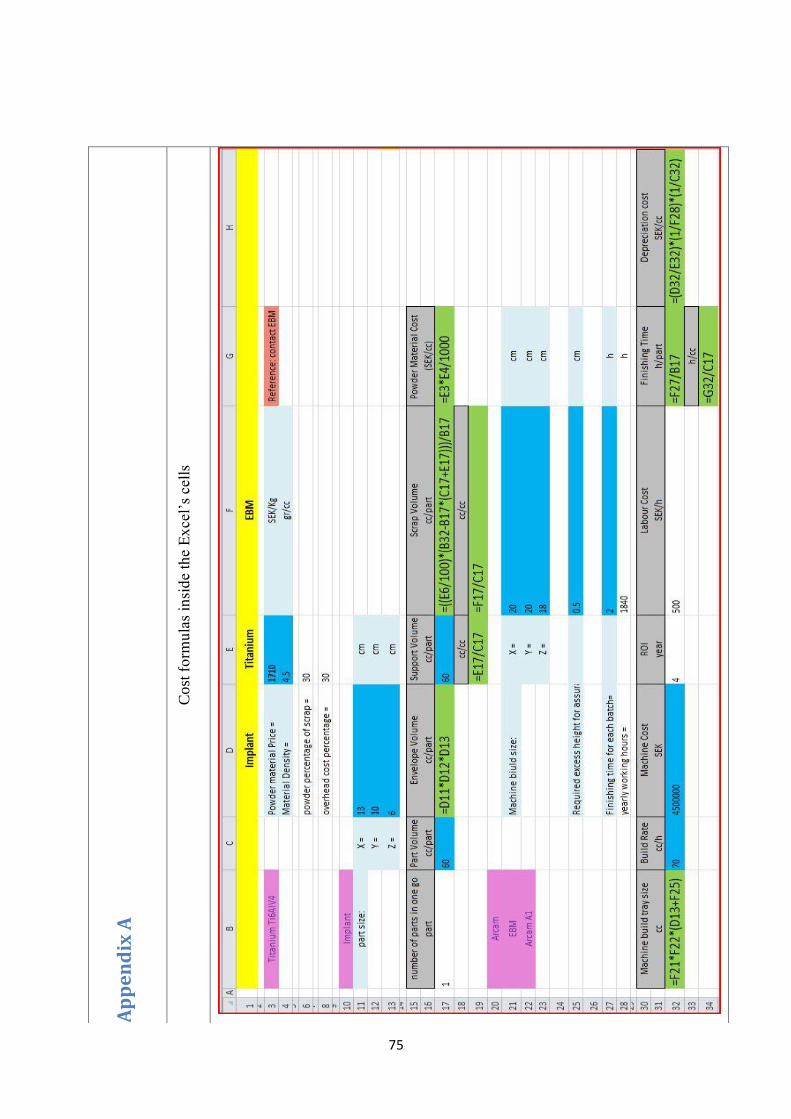
75
Ap
pe
nd
ix A
Co
st f
orm
ula
s in
sid
e th
e E
xce
l’s
cell
s
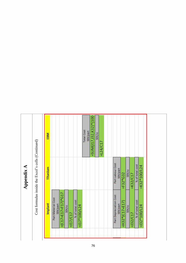
76
Ap
pen
dix
A
Co
st f
orm
ula
s in
sid
e th
e E
xce
l’s
cell
s (C
on
tin
ued
)

77
Ap
pe
nd
ix B
Ex
amp
le 1
Co
st F
orm
ula
tio
n
Imp
lan
tTi
tan
ium
EBM
Po
wd
er
mat
eri
al P
rice
=17
10SE
K/K
gR
efe
ren
ce: c
on
tact
EB
M
Mat
eri
al D
en
sity
=4.
5gr
/cc
po
wd
er
pe
rce
nta
ge o
f sc
rap
=30
ove
rhe
ad c
ost
pe
rce
nta
ge =
30
X =
13cm
Y =
10cm
Z =
6cm
Par
t V
olu
me
Enve
lop
e V
olu
me
Sup
po
rt V
olu
me
Scra
p V
olu
me
Po
wd
er
Mat
eri
al C
ost
cc/p
art
cc/p
art
cc/p
art
cc/p
art
(SEK
/cc)
6078
060
744
7.69
5
cc/c
ccc
/cc
1.0
12.4
Mac
hin
e b
iuld
siz
e:
X =
20cm
Y =
20cm
Z =
18cm
Re
qu
ire
d e
xce
ss h
eig
ht
for
assu
ran
ce, p
latf
orm
… =
0.5
cm
Fin
ish
ing
tim
e f
or
eac
h b
atch
= 2
h
year
ly w
ork
ing
ho
urs
=18
40h
Bu
ild
Rat
eM
ach
ine
Co
stR
OI
Lab
ou
r C
ost
Fin
ish
ing
Tim
eD
ep
reci
atio
n c
ost
cc/h
SEK
year
SEK
/hh
/par
tSE
K/c
c
7045
0000
04
500
28.
7
h/c
c
0.03
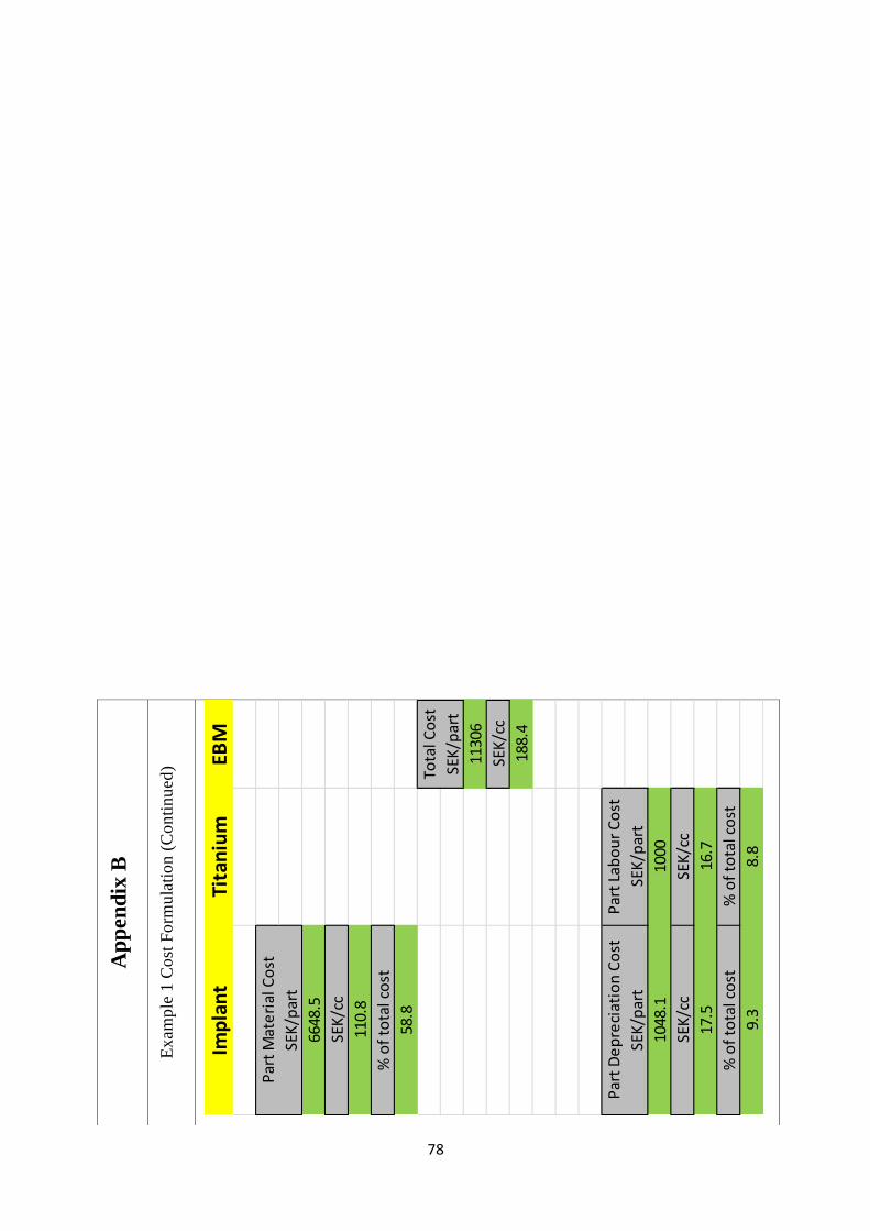
78
Ap
pen
dix
B
Ex
amp
le 1
Co
st F
orm
ula
tio
n (
Co
nti
nu
ed)
Imp
lan
tTi
tan
ium
EBM
Par
t M
ate
rial
Co
st
SEK
/par
t
6648
.5
SEK
/cc
110.
8
% o
f to
tal c
ost
58.8
Tota
l Co
st
SEK
/par
t
1130
6
SEK
/cc
188.
4
Par
t D
ep
reci
atio
n C
ost
Par
t La
bo
ur
Co
st
SEK
/par
tSE
K/p
art
1048
.110
00
SEK
/cc
SEK
/cc
17.5
16.7
% o
f to
tal c
ost
% o
f to
tal c
ost
9.3
8.8

79
Ap
pen
dix
B
Ex
amp
le 1
Co
st F
orm
ula
tio
n (
Co
nti
nu
ed)
Imp
lan
tTi
tan
ium
DM
LS
Tita
niu
m T
i6A
lV4
Po
wd
er
mat
eri
al P
rice
=47
60SE
K/K
gR
efe
ren
ce: p
df
Mat
eri
al D
en
sity
=4.
5gr
/cc
po
wd
er
pe
rce
nta
ge o
f sc
rap
=30
ove
rhe
ad c
ost
pe
rce
nta
ge =
30
Imp
lan
t
par
t si
ze:
X =
13cm
Y =
10cm
Z =
6cm
nu
mb
er
of
par
ts in
on
e g
oP
art
Vo
lum
eEn
velo
pe
Vo
lum
eSu
pp
ort
Vo
lum
eSc
rap
Vo
lum
eP
ow
de
r M
ate
rial
Co
st
par
tcc
/par
tcc
/par
tcc
/par
tcc
/par
t(S
EK/c
c)
160
780
6011
82.7
521
.42
cc/c
ccc
/cc
1.0
19.7
EOS
SLS
(DM
LS)
Mac
hin
e b
iuld
siz
e:
X =
25cm
M28
0Y
=25
cm
Z =
3.25
cm
Re
qu
ire
d e
xce
ss h
eig
ht
for
assu
ran
ce, p
latf
orm
… =
0.5
cm
Fin
ish
ing
tim
e f
or
eac
h b
atch
= 2
h
year
ly w
ork
ing
ho
urs
=18
40h
Mac
hin
e b
uil
d t
ray
size
Bu
ild
Rat
eM
ach
ine
Co
stR
OI
Lab
ou
r C
ost
Fin
ish
ing
Tim
eD
ep
reci
atio
n c
ost
cccc
/hSE
Kye
arSE
K/h
h/p
art
SEK
/cc
4062
.518
3800
000
450
02
28.7
h/c
c
0.0

80
Ap
pen
dix
B
Ex
amp
le 1
Co
st F
orm
ula
tio
n (
Co
nti
nu
ed)
Imp
lan
tTi
tan
ium
DM
LSP
art
Mat
eri
al C
ost
SEK
/par
t
2790
4.9
SEK
/cc
465.
1
% o
f to
tal c
ost
66.4
Tota
l Co
st
SEK
/par
t
4205
1
SEK
/cc
700.
9
Par
t D
ep
reci
atio
n C
ost
Par
t La
bo
ur
Co
st
SEK
/par
tSE
K/p
art
3442
.010
00
SEK
/cc
SEK
/cc
57.4
16.7
% o
f to
tal c
ost
% o
f to
tal c
ost
8.2
2.4

81
A
pp
en
dix
C
Ex
amp
le 2
Co
st F
orm
ula
tio
n
Ae
rosp
ace
par
tTi
tan
ium
EBM
Tita
niu
m T
i6A
lV4
Po
wd
er
mat
eri
al P
rice
=17
10SE
K/K
gR
efe
ren
ce: c
on
tact
EB
M
Mat
eri
al D
en
sity
=4.
5gr
/cc
po
wd
er
pe
rce
nta
ge o
f sc
rap
=30
ove
rhe
ad c
ost
pe
rce
nta
ge =
30
Ae
rosp
ace
par
t
par
t si
ze:
X =
3cm
Y =
3cm
Z =
3cm
nu
mb
er
of
par
ts in
on
e g
oP
art
Vo
lum
eEn
velo
pe
Vo
lum
eSu
pp
ort
Vo
lum
eSc
rap
Vo
lum
eP
ow
de
r M
ate
rial
Co
st
par
tcc
/par
tcc
/par
tcc
/par
tcc
/par
t(S
EK/c
c)
19
275
415.
87.
695
cc/c
ccc
/cc
0.6
46.2
Arc
am
EBM
Mac
hin
e b
iuld
siz
e:
X =
20cm
Arc
am A
1Y
=20
cm
Z =
18cm
Re
qu
ire
d e
xce
ss h
eig
ht
for
assu
ran
ce, p
latf
orm
… =
0.5
cm
Fin
ish
ing
tim
e f
or
eac
h b
atch
= 2
h
year
ly w
ork
ing
ho
urs
=18
40h
Mac
hin
e b
uil
d t
ray
size
Bu
ild
Rat
eM
ach
ine
Co
stR
OI
Lab
ou
r C
ost
Fin
ish
ing
Tim
eD
ep
reci
atio
n c
ost
cccc
/hSE
Kye
arSE
K/h
h/p
art
SEK
/cc
1400
7045
0000
04
500
28.
7
h/c
c
0.2

82
Ap
pen
dix
C
Ex
amp
le 2
Co
st F
orm
ula
tio
n (
Co
nti
nu
ed)
Ae
rosp
ace
par
tTi
tan
ium
EBM
Par
t M
ate
rial
Co
st
SEK
/par
t
3307
.3
SEK
/cc
367.
5
% o
f to
tal c
ost
57.4
Tota
l Co
st
SEK
/par
t
5758
SEK
/cc
639.
8
Par
t D
ep
reci
atio
n C
ost
Par
t La
bo
ur
Co
st
SEK
/par
tSE
K/p
art
122.
310
00
SEK
/cc
SEK
/cc
13.6
111.
1
% o
f to
tal c
ost
% o
f to
tal c
ost
2.1
17.4
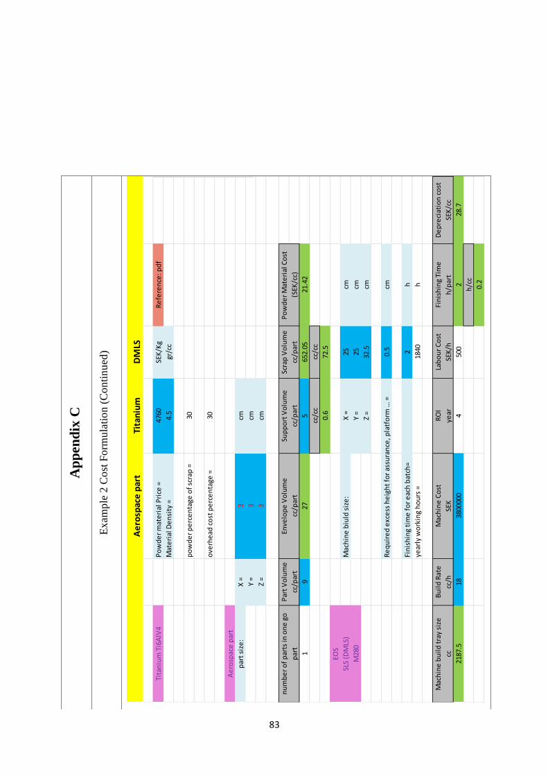
83
Ap
pen
dix
C
Ex
amp
le 2
Co
st F
orm
ula
tio
n (
Co
nti
nu
ed)
Ae
rosp
ace
par
tTi
tan
ium
DM
LS
Tita
niu
m T
i6A
lV4
Po
wd
er
mat
eri
al P
rice
=47
60SE
K/K
gR
efe
ren
ce: p
df
Mat
eri
al D
en
sity
=4.
5gr
/cc
po
wd
er
pe
rce
nta
ge o
f sc
rap
=30
ove
rhe
ad c
ost
pe
rce
nta
ge =
30
Ae
rosp
ace
par
t
par
t si
ze:
X =
3cm
Y =
3cm
Z =
3cm
nu
mb
er
of
par
ts in
on
e g
oP
art
Vo
lum
eEn
velo
pe
Vo
lum
eSu
pp
ort
Vo
lum
eSc
rap
Vo
lum
eP
ow
de
r M
ate
rial
Co
st
par
tcc
/par
tcc
/par
tcc
/par
tcc
/par
t(S
EK/c
c)
19
275
652.
0521
.42
cc/c
ccc
/cc
0.6
72.5
EOS
SLS
(DM
LS)
Mac
hin
e b
iuld
siz
e:
X =
25cm
M28
0Y
=25
cm
Z =
32.5
cm
Re
qu
ire
d e
xce
ss h
eig
ht
for
assu
ran
ce, p
latf
orm
… =
0.5
cm
Fin
ish
ing
tim
e f
or
eac
h b
atch
= 2
h
year
ly w
ork
ing
ho
urs
=18
40h
Mac
hin
e b
uil
d t
ray
size
Bu
ild
Rat
eM
ach
ine
Co
stR
OI
Lab
ou
r C
ost
Fin
ish
ing
Tim
eD
ep
reci
atio
n c
ost
cccc
/hSE
Kye
arSE
K/h
h/p
art
SEK
/cc
2187
.518
3800
000
450
02
28.7
h/c
c
0.2

84
A
pp
en
dix
C
Ex
amp
le 2
Co
st F
orm
ula
tio
n (
Co
nti
nu
ed)
Ae
rosp
ace
par
tTi
tan
ium
DM
LSP
art
Mat
eri
al C
ost
SEK
/par
t
1426
6.8
SEK
/cc
1585
.2
% o
f to
tal c
ost
70.0
Tota
l Co
st
SEK
/par
t
2036
9
SEK
/cc
2263
.2
Par
t D
ep
reci
atio
n C
ost
Par
t La
bo
ur
Co
st
SEK
/par
tSE
K/p
art
401.
610
00
SEK
/cc
SEK
/cc
44.6
111.
1
% o
f to
tal c
ost
% o
f to
tal c
ost
2.0
4.9

85
Ap
pe
nd
ix D
Ex
amp
le 3
Co
st F
orm
ula
tio
n
Bu
mp
er
Po
lyam
ide
SLS
Po
lyam
ide
(P
A12
)P
ow
de
r m
ate
rial
Pri
ce =
573
SEK
/Kg
Re
fere
nce
: co
nta
ct E
OS
Mat
eri
al D
en
sity
=1.
01gr
/cc
po
wd
er
pe
rce
nta
ge o
f sc
rap
=30
ove
rhe
ad c
ost
pe
rce
nta
ge =
30
Bu
mp
er
par
t si
ze:
X =
6.16
cm
Y =
11.8
2cm
Z =
1.38
cm
nu
mb
er
of
par
ts in
on
e g
oP
art
Vo
lum
eEn
velo
pe
Vo
lum
eSu
pp
ort
Vo
lum
eSc
rap
Vo
lum
eP
ow
de
r M
ate
rial
Co
st
par
tcc
/par
tcc
/par
tcc
/par
tcc
/par
t(S
EK/c
c)
14
100.
4794
560
280.
80.
5787
3
de
pe
nd
ing
on
th
e d
esi
gncc
/cc
cc/c
c
0.0
70.2
EOS
SLS
Mac
hin
e b
uil
d s
ize
:X
=20
cm
Form
iga
P10
0Y
=25
cm
Z =
33cm
Re
qu
ire
d e
xce
ss h
eig
ht
for
assu
ran
ce, p
latf
orm
… =
0.5
cm
Fin
ish
ing
tim
e f
or
eac
h b
atch
= 2
h
year
ly w
ork
ing
ho
urs
=18
40h
Mac
hin
e b
uil
d t
ray
size
Bu
ild
Rat
eM
ach
ine
Co
stR
OI
Lab
ou
r C
ost
Fin
ish
ing
Tim
eD
ep
reci
atio
n c
ost
cccc
/hSE
Kye
arSE
K/h
h/p
art
SEK
/cc
940
217
1000
04
500
211
6.2
h/c
c
0.5

86
Ap
pen
dix
D
Ex
amp
le 3
Co
st F
orm
ula
tio
n (
Co
nti
nu
ed)
Bu
mp
er
Po
lyam
ide
SLS
Par
t M
ate
rial
Co
st
SEK
/par
t
164.
8
SEK
/cc
41.2
% o
f to
tal c
ost
7.8
Tota
l Co
st
SEK
/par
t
2118
SEK
/cc
529.
6
Par
t D
ep
reci
atio
n C
ost
Par
t La
bo
ur
Co
st
SEK
/par
tSE
K/p
art
464.
710
00
SEK
/cc
SEK
/cc
116.
225
0.0
% o
f to
tal c
ost
% o
f to
tal c
ost
21.9
47.2

87
Ap
pen
dix
D
Ex
amp
le 3
Co
st F
orm
ula
tio
n (
Co
nti
nu
ed)
Bu
mp
er
AB
SFD
M
AB
SP
ow
de
r m
ate
rial
Pri
ce =
2800
SEK
/Kg
Re
fere
nce
: co
nta
ct P
rote
ch
Mat
eri
al D
en
sity
=1.
04gr
/cc
po
wd
er
pe
rce
nta
ge o
f sc
rap
=30
ove
rhe
ad c
ost
pe
rce
nta
ge =
30
Bu
mp
er
par
t si
ze:
X =
6.16
cm
Y =
11.8
2cm
Z =
1.38
cm
nu
mb
er
of
par
ts in
on
e g
oP
art
Vo
lum
eEn
velo
pe
Vo
lum
eSu
pp
ort
Vo
lum
eSc
rap
Vo
lum
eP
ow
de
r M
ate
rial
Co
st
par
tcc
/par
tcc
/par
tcc
/par
tcc
/par
t(S
EK/c
c)
14
100.
4794
561
351
2.91
2
cc/c
ccc
/cc
0.3
87.8
Stra
tasy
s
FDM
Mac
hin
e b
iuld
siz
e:
X =
25cm
Dim
en
sio
n B
ST 1
200e
sY
=25
cm
Z =
30cm
Re
qu
ire
d e
xce
ss h
eig
ht
for
assu
ran
ce, p
latf
orm
… =
0.5
cm
Fin
ish
ing
tim
e f
or
eac
h b
atch
= 2
h
year
ly w
ork
ing
ho
urs
=18
40h
Mac
hin
e b
uil
d t
ray
size
Bu
ild
Rat
eM
ach
ine
Co
stR
OI
Lab
ou
r C
ost
Fin
ish
ing
Tim
eD
ep
reci
atio
n c
ost
cccc
/hSE
Kye
arSE
K/h
h/p
art
SEK
/cc
1175
2.54
2109
004
500
211
.3
h/c
c
0.5
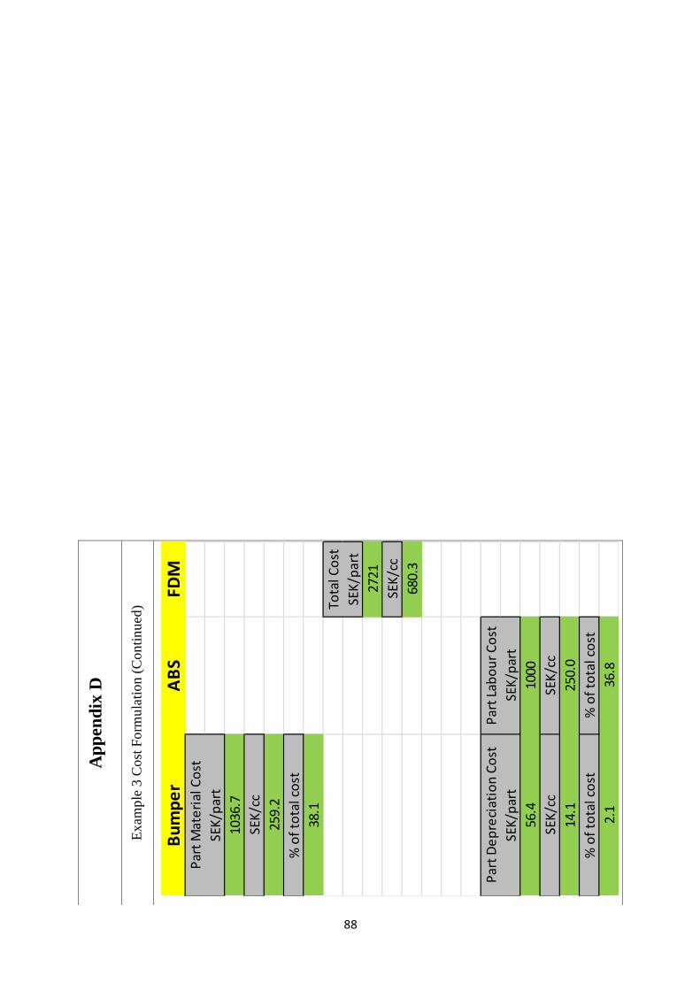
88
Ap
pen
dix
D
Ex
amp
le 3
Co
st F
orm
ula
tio
n (
Co
nti
nu
ed)
Bu
mp
er
AB
SFD
MP
art
Mat
eri
al C
ost
SEK
/par
t
1036
.7
SEK
/cc
259.
2
% o
f to
tal c
ost
38.1
Tota
l Co
st
SEK
/par
t
2721
SEK
/cc
680.
3
Par
t D
ep
reci
atio
n C
ost
Par
t La
bo
ur
Co
st
SEK
/par
tSE
K/p
art
56.4
1000
SEK
/cc
SEK
/cc
14.1
250.
0
% o
f to
tal c
ost
% o
f to
tal c
ost
2.1
36.8
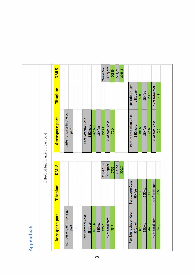
89
Ap
pe
nd
ix E
Eff
ect
of
bat
ch s
ize
on
par
t co
st

90