additive manufacturing of internal features for
TRANSCRIPT

ADDITIVE MANUFACTURING OF INTERNAL FEATURES FOR MANIPULATION OF STRUCTURAL DYNAMICS
Emma D. Betters1, Justin West1, Mark Noakes2, Andrzej Nycz2,
Scott Smith2, and Tony L. Schmitz1 1Department of Mechanical, Aerospace, and Biomedical Engineering
University of Tennessee, Knoxville, TN 2Manufacturing Demonstration Facility
Oak Ridge National Laboratory, Oak Ridge, TN ABSTRACT A component was designed and manufactured in two configurations using a wire arc additive process. The first configuration was an open channel, while the second contained a dynamic absorber in the internal cavity. Dynamic measurements of the two components demonstrated the ability to print internal features which, when designed appropriately, can be used to increase the dynamic stiffness of structures. Keywords: Additive manufacturing, machining, frequency response function, dynamic absorber INTRODUCTION In machining processes, the machine structure, spindle, holder, tool, and workpiece collectively compose a dynamic system that defines permissible cutting parameters. Exceeding the limiting depth of cut for a particular spindle speeds leads to chatter, or self-excited vibration that yields large forces, poor surface finish, and, potentially, damage to the workpiece, tool, or spindle. In an effort to improve dynamic stiffness, the machine base can be designed specifically for higher stiffness and damping. However, traditional casting processes for machine bases are geometrically limited, labor intensive, and expensive.
An alternative approach is to use an additive manufacturing process to produce the machine base. The additive approach offers significant design freedom for internal features which can be used to alter the dynamic characteristics of the system or to maximize the dynamic stiffness at a given frequency, for example.
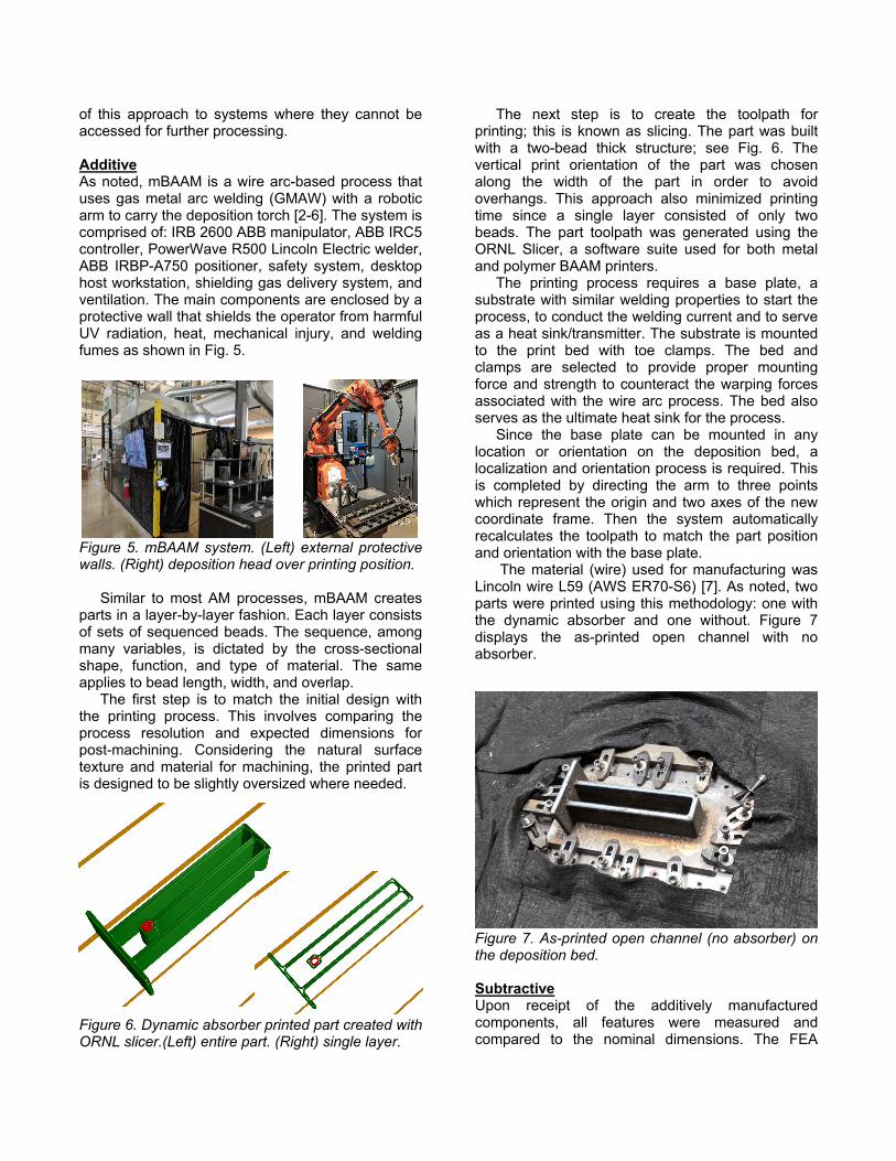
A pair of components was designed and fabricated to demonstrate the ability of the Metal Big Area Additive Manufacturing (mBAAM) process to print internal features intended to modify the structure’s dynamics (e.g., by altering the natural frequency or increasing the dynamics stiffness). The first component was an open channel attached to a base. The second component was identical, except for the addition of a dynamic absorber inside the
open cavity. The absorber was designed to maximize the dynamic stiffness at the natural frequency of the original, open channel design. Figure 1 describes the parameterized component geometries; Table 1 lists the dimensions.
This paper presents: the design and finite element analysis validation of the dynamic absorber; the additive and subtractive manufacturing processes; and the measured frequency response functions (FRFs) for the final components.
Figure 1: Dimensions of the (left) open channel and (right) open channel with dynamic absorber designs. w is the dimension into the page. Table 1: Initial design dimensions (mm).
L 300 T 10 h 69 w 50 l 225 t 12 a 25 b 25
DESIGN AND MODELING The dimensions of the open channel were based on the wire arc additive process resolution and a
minimum recommended printed wall thickness of 12 mm to enable the outer surfaces to be finish machined. The final machined dimensions (rather than rough printed dimensions) are provided in Table 1. The first natural frequency of the open channel was determined using finite element analysis (FEA). This frequency was used as the design point for the dynamic absorber.
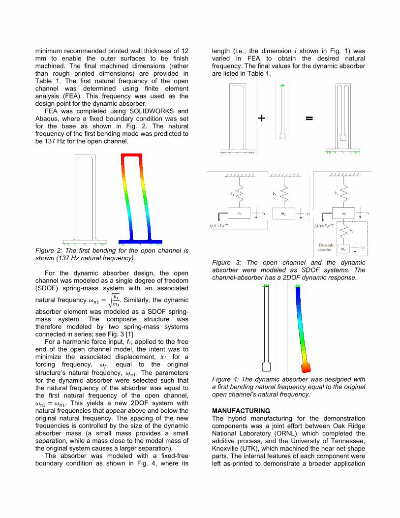
FEA was completed using SOLIDWORKS and Abaqus, where a fixed boundary condition was set for the base as shown in Fig. 2. The natural frequency of the first bending mode was predicted to be 137 Hz for the open channel.
Figure 2: The first bending for the open channel is shown (137 Hz natural frequency).
For the dynamic absorber design, the open
channel was modeled as a single degree of freedom (SDOF) spring-mass system with an associated
natural frequency 𝜔𝜔𝑛𝑛1 = �𝑘𝑘1𝑚𝑚1
. Similarly, the dynamic
absorber element was modeled as a SDOF spring-mass system. The composite structure was therefore modeled by two spring-mass systems connected in series; see Fig. 3 [1].
For a harmonic force input, f1, applied to the free end of the open channel model, the intent was to minimize the associated displacement, x1, for a forcing frequency, 𝜔𝜔𝑓𝑓, equal to the original structure’s natural frequency, 𝜔𝜔𝑛𝑛1. The parameters for the dynamic absorber were selected such that the natural frequency of the absorber was equal to the first natural frequency of the open channel, 𝜔𝜔𝑛𝑛2 = 𝜔𝜔𝑛𝑛1. This yields a new 2DOF system with natural frequencies that appear above and below the original natural frequency. The spacing of the new frequencies is controlled by the size of the dynamic absorber mass (a small mass provides a small separation, while a mass close to the modal mass of the original system causes a larger separation).
The absorber was modeled with a fixed-free boundary condition as shown in Fig. 4, where its
length (i.e., the dimension l shown in Fig. 1) was varied in FEA to obtain the desired natural frequency. The final values for the dynamic absorber are listed in Table 1.
Figure 3: The open channel and the dynamic absorber were modeled as SDOF systems. The channel-absorber has a 2DOF dynamic response.
Figure 4: The dynamic absorber was designed with a first bending natural frequency equal to the original open channel’s natural frequency. MANUFACTURING The hybrid manufacturing for the demonstration components was a joint effort between Oak Ridge National Laboratory (ORNL), which completed the additive process, and the University of Tennessee, Knoxville (UTK), which machined the near net shape parts. The internal features of each component were left as-printed to demonstrate a broader application
of this approach to systems where they cannot be accessed for further processing. Additive As noted, mBAAM is a wire arc-based process that uses gas metal arc welding (GMAW) with a robotic arm to carry the deposition torch [2-6]. The system is comprised of: IRB 2600 ABB manipulator, ABB IRC5 controller, PowerWave R500 Lincoln Electric welder, ABB IRBP-A750 positioner, safety system, desktop host workstation, shielding gas delivery system, and ventilation. The main components are enclosed by a protective wall that shields the operator from harmful UV radiation, heat, mechanical injury, and welding fumes as shown in Fig. 5.
Figure 5. mBAAM system. (Left) external protective walls. (Right) deposition head over printing position.
Similar to most AM processes, mBAAM creates parts in a layer-by-layer fashion. Each layer consists of sets of sequenced beads. The sequence, among many variables, is dictated by the cross-sectional shape, function, and type of material. The same applies to bead length, width, and overlap.
The first step is to match the initial design with the printing process. This involves comparing the process resolution and expected dimensions for post-machining. Considering the natural surface texture and material for machining, the printed part is designed to be slightly oversized where needed.
Figure 6. Dynamic absorber printed part created with ORNL slicer.(Left) entire part. (Right) single layer.
The next step is to create the toolpath for printing; this is known as slicing. The part was built with a two-bead thick structure; see Fig. 6. The vertical print orientation of the part was chosen along the width of the part in order to avoid overhangs. This approach also minimized printing time since a single layer consisted of only two beads. The part toolpath was generated using the ORNL Slicer, a software suite used for both metal and polymer BAAM printers.
The printing process requires a base plate, a substrate with similar welding properties to start the process, to conduct the welding current and to serve as a heat sink/transmitter. The substrate is mounted to the print bed with toe clamps. The bed and clamps are selected to provide proper mounting force and strength to counteract the warping forces associated with the wire arc process. The bed also serves as the ultimate heat sink for the process.
Since the base plate can be mounted in any location or orientation on the deposition bed, a localization and orientation process is required. This is completed by directing the arm to three points which represent the origin and two axes of the new coordinate frame. Then the system automatically recalculates the toolpath to match the part position and orientation with the base plate.
The material (wire) used for manufacturing was Lincoln wire L59 (AWS ER70-S6) [7]. As noted, two parts were printed using this methodology: one with the dynamic absorber and one without. Figure 7 displays the as-printed open channel with no absorber.
Figure 7. As-printed open channel (no absorber) on the deposition bed. Subtractive Upon receipt of the additively manufactured components, all features were measured and compared to the nominal dimensions. The FEA

model was updated using actual dimensions for the dynamic absorber. Due to the surface variation of the wire arc additive process, an average of measurements at ten locations along each feature was applied. The updated model was used to determine the amount of material to be removed from each face. The predicted natural frequency of the finish machined open channel was 137.4 Hz.
The primary machining challenge was the lack of a clear datum. In the first operation, the build plate was assumed to be flat. It was stoned to remove macro height deviations and was clamped directly to the machine table. Each part was then faced to provide a reference once the build plate was removed; see Fig. 8. Next, the base plate was machined away and the associated surface machined to produce two parallel surfaces which could then be used for fixturing during the machining of the remaining sides.
Figure 8: To machine the first side, the build plate was clamped to the machine table. The top surface was then faced.
Figure 9: The parts were clamped in a vise and a machining parallel was used as an indicating surface for the dial indicator.
Prior to machining, the walls were sanded and stoned to remove debris and protrusions from the wire arc process. The previously machined front and back surfaces were clamped in a vise and a digital dial indicator was used to align the part; see Fig. 9. Each remaining surface was indicated and finished in the same way; see Fig. 10.
Figure 10: The parts were fixtured to an angle plate to finish the top and bottom surfaces.
Figure 11: Impact testing was used to measure the final part FRFs.
The finished parts were clamped to a rigid table and a direct FRF was measured for both the open channel and the channel with the internal dynamic absorber. Impact testing was used for the FRF measurements, where an instrumented hammer is used to excite the structure and a low mass accelerometer is used to record the vibration response; see Fig. 11. RESULTS The measured FRF for the open channel is shown in Fig. 12, where the first natural frequency is 127.8
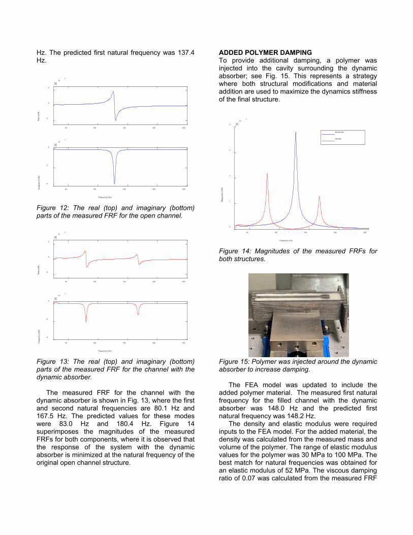
Hz. The predicted first natural frequency was 137.4 Hz.
Figure 12: The real (top) and imaginary (bottom) parts of the measured FRF for the open channel.
Figure 13: The real (top) and imaginary (bottom) parts of the measured FRF for the channel with the dynamic absorber.
The measured FRF for the channel with the dynamic absorber is shown in Fig. 13, where the first and second natural frequencies are 80.1 Hz and 167.5 Hz. The predicted values for these modes were 83.0 Hz and 180.4 Hz. Figure 14 superimposes the magnitudes of the measured FRFs for both components, where it is observed that the response of the system with the dynamic absorber is minimized at the natural frequency of the original open channel structure.
ADDED POLYMER DAMPING To provide additional damping, a polymer was injected into the cavity surrounding the dynamic absorber; see Fig. 15. This represents a strategy where both structural modifications and material addition are used to maximize the dynamics stiffness of the final structure.
Figure 14: Magnitudes of the measured FRFs for both structures.
Figure 15: Polymer was injected around the dynamic absorber to increase damping.
The FEA model was updated to include the added polymer material. The measured first natural frequency for the filled channel with the dynamic absorber was 148.0 Hz and the predicted first natural frequency was 148.2 Hz.
The density and elastic modulus were required inputs to the FEA model. For the added material, the density was calculated from the measured mass and volume of the polymer. The range of elastic modulus values for the polymer was 30 MPa to 100 MPa. The best match for natural frequencies was obtained for an elastic modulus of 52 MPa. The viscous damping ratio of 0.07 was calculated from the measured FRF
50 100 150 200 250
-2
0
2
Rea
l (m
/N)
10-5
50 100 150 200 250
Frequency (Hz)
-4
-2
0
Imag
inar
y (m
/N)
10-5
50 100 150 200 250
-2
0
2
Rea
l (m
/N)
10-5
50 100 150 200 250
Frequency (Hz)
-4
-2
0
Imag
inar
y (m
/N)
10-5
50 100 150 200 250
Frequency (Hz)
0
1
2
3
4
Mag
nitu
de (m
/N)
10-5
No absorber
Absorber
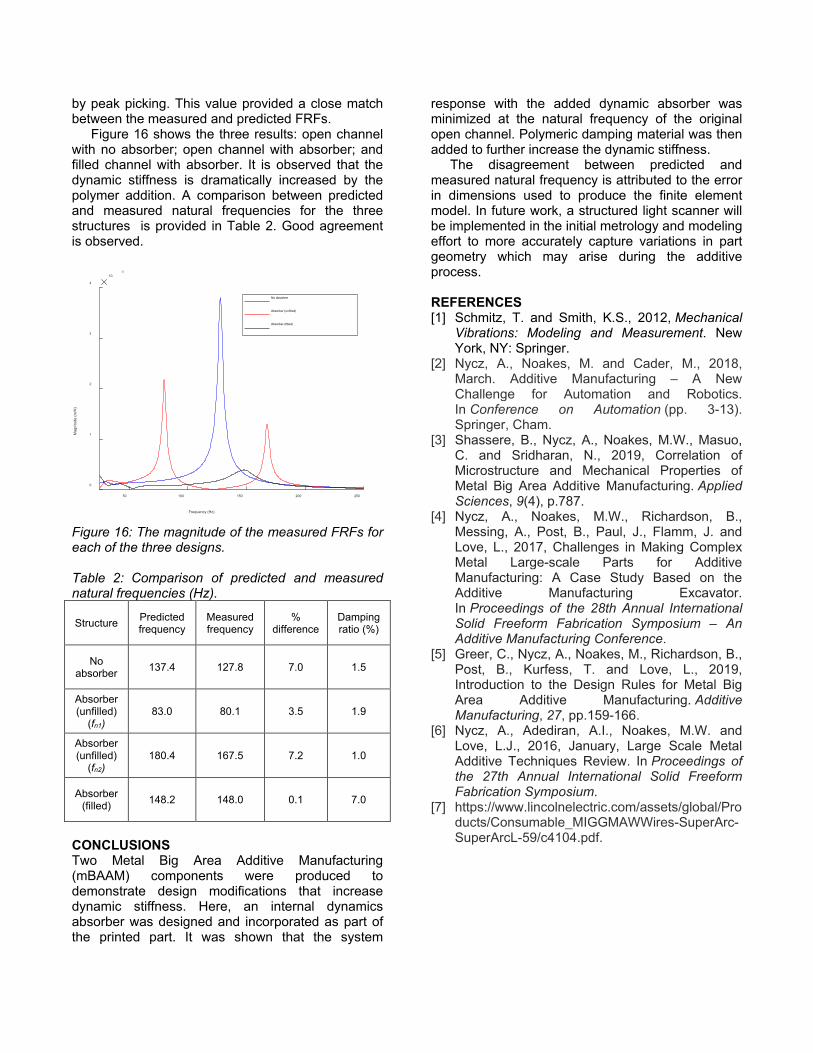
by peak picking. This value provided a close match between the measured and predicted FRFs. Figure 16 shows the three results: open channel with no absorber; open channel with absorber; and filled channel with absorber. It is observed that the dynamic stiffness is dramatically increased by the polymer addition. A comparison between predicted and measured natural frequencies for the three structures is provided in Table 2. Good agreement is observed.
Figure 16: The magnitude of the measured FRFs for each of the three designs. Table 2: Comparison of predicted and measured natural frequencies (Hz).
Structure Predicted frequency
Measured frequency
% difference
Damping ratio (%)
No absorber 137.4 127.8 7.0 1.5
Absorber (unfilled)
(fn1) 83.0 80.1 3.5 1.9
Absorber (unfilled)
(fn2) 180.4 167.5 7.2 1.0
Absorber (filled) 148.2 148.0 0.1 7.0
CONCLUSIONS Two Metal Big Area Additive Manufacturing (mBAAM) components were produced to demonstrate design modifications that increase dynamic stiffness. Here, an internal dynamics absorber was designed and incorporated as part of the printed part. It was shown that the system
response with the added dynamic absorber was minimized at the natural frequency of the original open channel. Polymeric damping material was then added to further increase the dynamic stiffness.
The disagreement between predicted and measured natural frequency is attributed to the error in dimensions used to produce the finite element model. In future work, a structured light scanner will be implemented in the initial metrology and modeling effort to more accurately capture variations in part geometry which may arise during the additive process. REFERENCES [1] Schmitz, T. and Smith, K.S., 2012, Mechanical
Vibrations: Modeling and Measurement. New York, NY: Springer.
[2] Nycz, A., Noakes, M. and Cader, M., 2018, March. Additive Manufacturing – A New Challenge for Automation and Robotics. In Conference on Automation (pp. 3-13). Springer, Cham.
[3] Shassere, B., Nycz, A., Noakes, M.W., Masuo, C. and Sridharan, N., 2019, Correlation of Microstructure and Mechanical Properties of Metal Big Area Additive Manufacturing. Applied Sciences, 9(4), p.787.
[4] Nycz, A., Noakes, M.W., Richardson, B., Messing, A., Post, B., Paul, J., Flamm, J. and Love, L., 2017, Challenges in Making Complex Metal Large-scale Parts for Additive Manufacturing: A Case Study Based on the Additive Manufacturing Excavator. In Proceedings of the 28th Annual International Solid Freeform Fabrication Symposium – An Additive Manufacturing Conference.
[5] Greer, C., Nycz, A., Noakes, M., Richardson, B., Post, B., Kurfess, T. and Love, L., 2019, Introduction to the Design Rules for Metal Big Area Additive Manufacturing. Additive Manufacturing, 27, pp.159-166.
[6] Nycz, A., Adediran, A.I., Noakes, M.W. and Love, L.J., 2016, January, Large Scale Metal Additive Techniques Review. In Proceedings of the 27th Annual International Solid Freeform Fabrication Symposium.
[7] https://www.lincolnelectric.com/assets/global/Products/Consumable_MIGGMAWWires-SuperArc-SuperArcL-59/c4104.pdf.
50 100 150 200 250
Frequency (Hz)
0
1
2
3
4
Mag
nitu
de (m
/N)
10-5
No absorber
Absorber (unfilled)
Absorber (filled)