additive manufacturing (am) - cdn0.scrvt.com · source: eos gmbh basic design rules for additive...
TRANSCRIPT

This presentation may contain confidential and/or privileged information.Any unauthorized copying, disclosure or distribution of the material in this document is strictly forbidden.
Additive Manufacturing (AM)Basic Design Rules for Additive Manufacturing
Basic Design Rules for Additive Manufacturing | EOS | 2Source: EOS GmbH
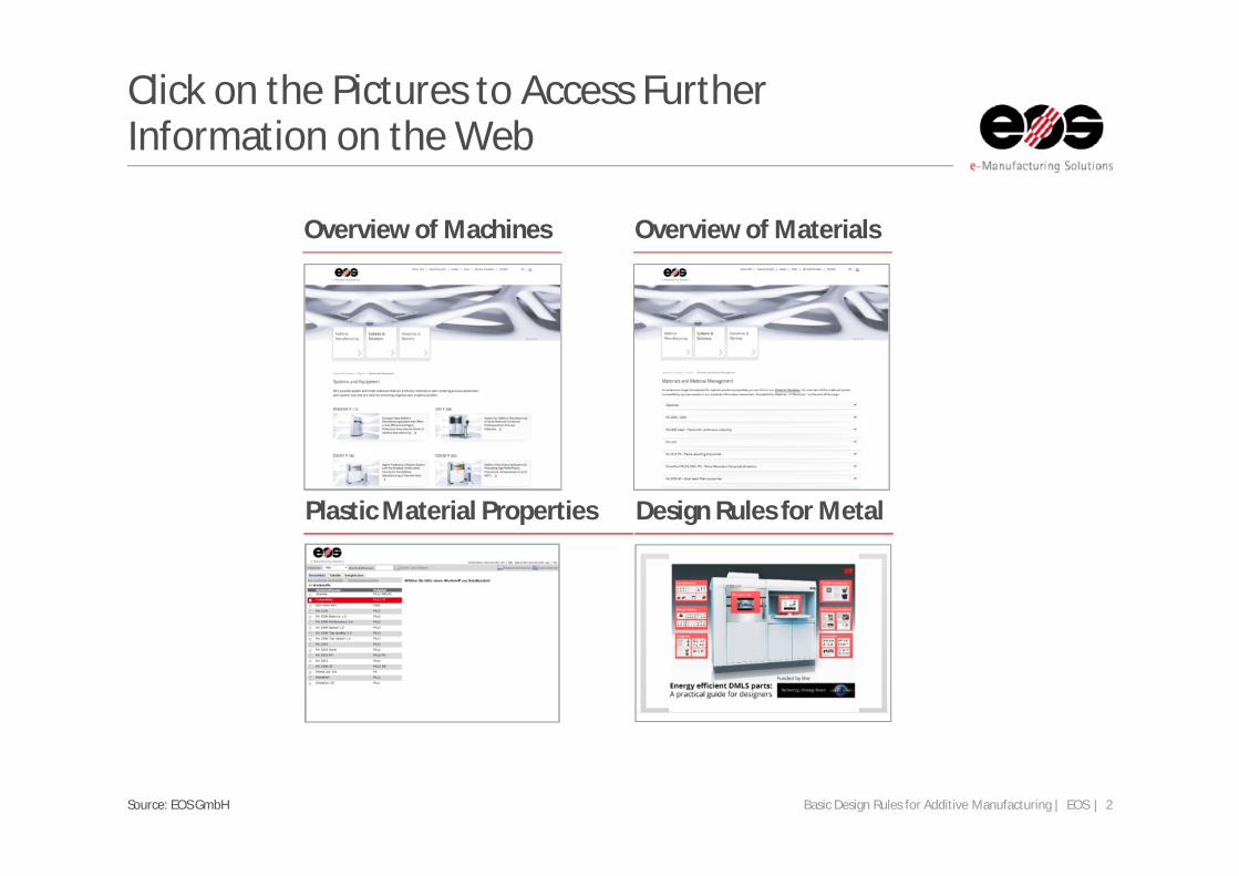
Click on the Pictures to Access Further Information on the Web
Overview of Machines Overview of Materials
Plastic Material Properties Design Rules for Metal

Basic Design Rules for Additive Manufacturing | EOS | 3Source: EOS GmbH
Additive Manufacturing Design Rules for Plastic
Basic Design Rules for Additive Manufacturing | EOS | 4Source: EOS GmbH
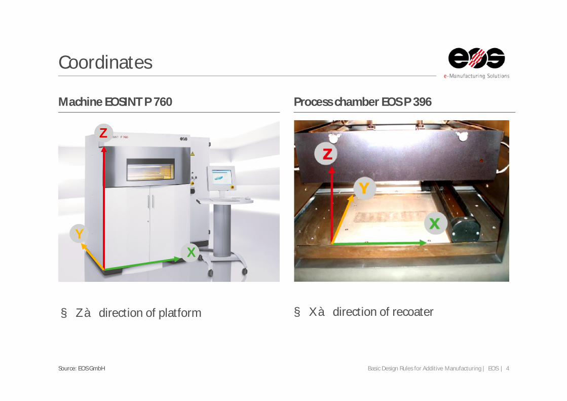
Coordinates
Machine EOSINT P 760 Process chamber EOS P 396
§ Z à direction of platform § X à direction of recoater
XY
Z
Basic Design Rules for Additive Manufacturing | EOS | 5Source: EOS GmbH
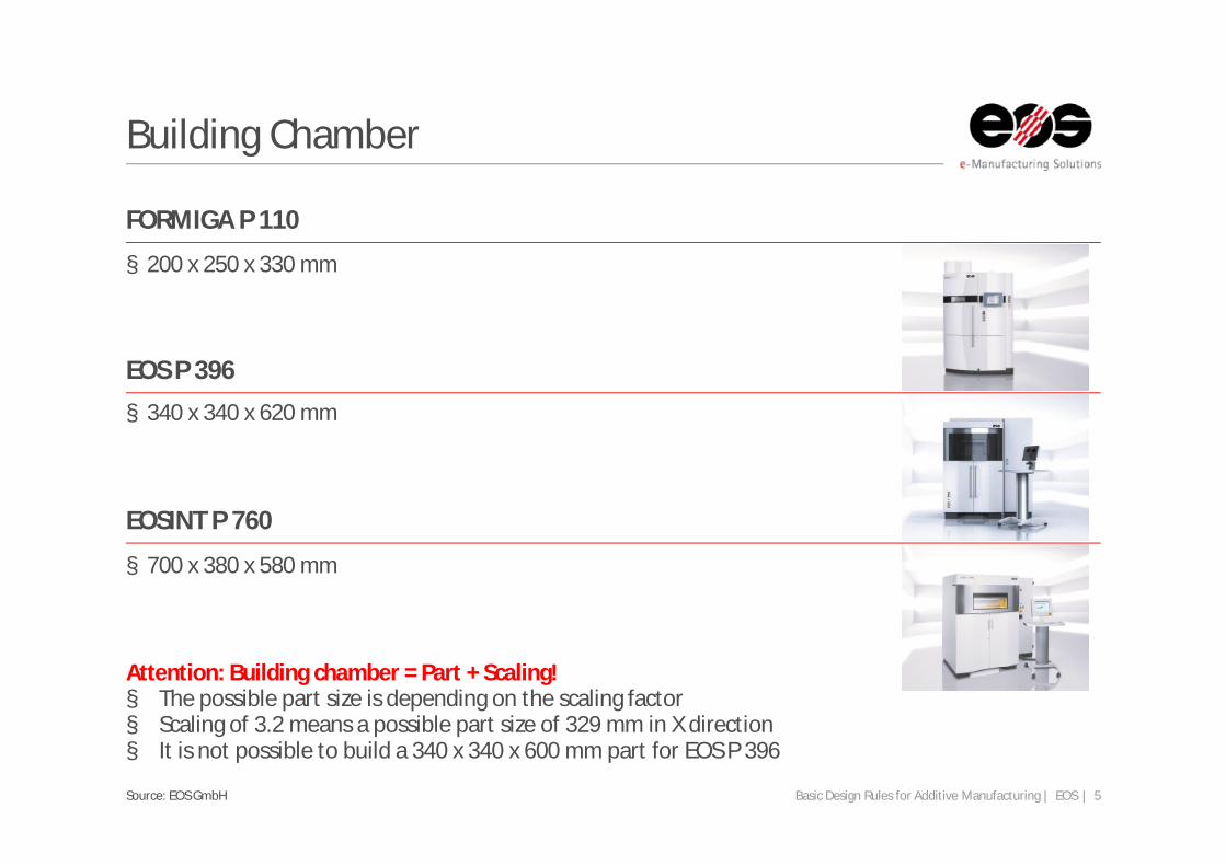
Building Chamber
FORMIGA P 110
EOS P 396
EOSINT P 760
§ 200 x 250 x 330 mm
§ 340 x 340 x 620 mm
§ 700 x 380 x 580 mm
Attention: Building chamber = Part + Scaling!§ The possible part size is depending on the scaling factor § Scaling of 3.2 means a possible part size of 329 mm in X direction§ It is not possible to build a 340 x 340 x 600 mm part for EOS P 396

Basic Design Rules for Additive Manufacturing | EOS | 6Source: EOS GmbH
Steps
Z
Y/X
>20°
§ To avoid steps on your surface, the angle of the plane should be 0° or >20° to the X-Y area§ Visibility and size depending on layer thickness

Basic Design Rules for Additive Manufacturing | EOS | 7Source: EOS GmbH
Hinges
§ Gaps (A) for Hinges: § x/y: 0.3 mm - 0.5 mm§ z: 0.5 mm - 0.6 mm
§ Variables:§ gap between bush and bolt (A)§ length of the hinge (B)§ diameter of the bolt (C)§ thickness of the surrounding
bushing (D) § building direction
§ With advance geometries smaller gaps are possible
Basic Design Rules for Additive Manufacturing | EOS | 8Source: EOS GmbH
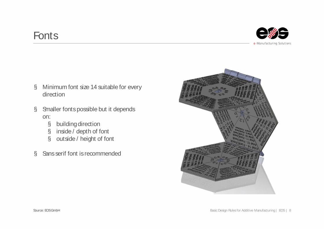
Fonts
§ Minimum font size 14 suitable for every direction
§ Smaller fonts possible but it depends on:§ building direction§ inside / depth of font § outside / height of font
§ Sans serif font is recommended
Basic Design Rules for Additive Manufacturing | EOS | 9Source: EOS GmbH
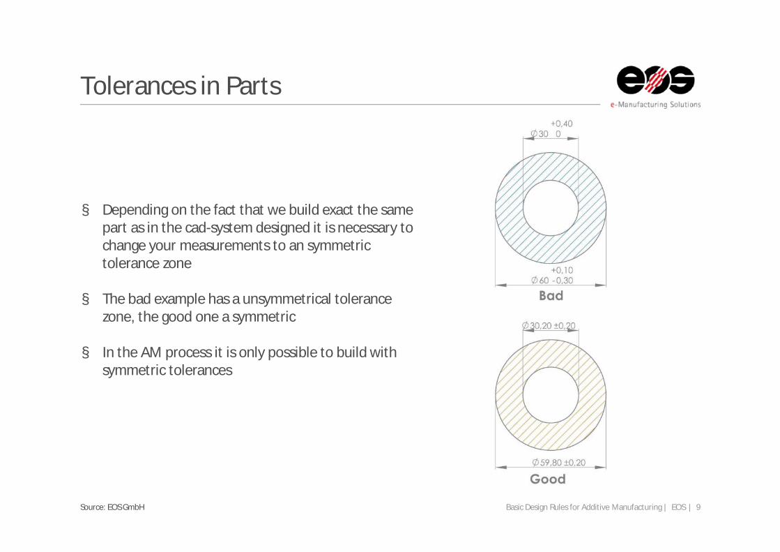
Tolerances in Parts
§ Depending on the fact that we build exact the same part as in the cad-system designed it is necessary to change your measurements to an symmetric tolerance zone
§ The bad example has a unsymmetrical tolerance zone, the good one a symmetric
§ In the AM process it is only possible to build with symmetric tolerances

Basic Design Rules for Additive Manufacturing | EOS | 10Source: EOS GmbH
Lose Connection
§ Use 0.1 mm distance for lose connection
§ A mal and female part without a gap have a press fit
§ Only for parts not built together! else see hinges
Basic Design Rules for Additive Manufacturing | EOS | 11Source: EOS GmbH
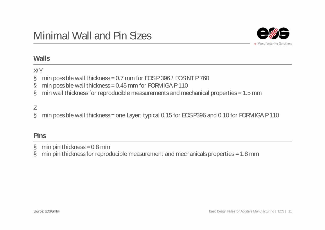
Minimal Wall and Pin Sizes
Walls
Pins
X/Y§ min possible wall thickness = 0.7 mm for EOS P 396 / EOSINT P 760§ min possible wall thickness = 0.45 mm for FORMIGA P 110§ min wall thickness for reproducible measurements and mechanical properties = 1.5 mm
Z§ min possible wall thickness = one Layer; typical 0.15 for EOS P396 and 0.10 for FORMIGA P 110
§ min pin thickness = 0.8 mm § min pin thickness for reproducible measurement and mechanicals properties = 1.8 mm

Basic Design Rules for Additive Manufacturing | EOS | 12Source: EOS GmbH
Gaps
The min size of a gap depends on the wall thickness of the part
0.5
0.6
0.7
0.8
0.30 mm 3.00 mm 6.00 mm
Gap width [mm]:
Wall thickness:
x
y

Basic Design Rules for Additive Manufacturing | EOS | 13Source: EOS GmbH
Holes
Possible min hole diameter depends on the thickness of the wall
Hole diameter:
0.5 mm
0.6 mm
0.7 mm
0.8 mm
Wall thickness: 0.30 mm 0.60 mm
x
y

Basic Design Rules for Additive Manufacturing | EOS | 14Source: EOS GmbH
Costs
Bad example Good example§ Costs depending on Z-height (machine hours)
and part volume (powder)
§ Reduce Z-height§ design parts as low as possible in Z§ stackable à increase filling rate
§ Reduce part volume§ integrated design§ lightweight design§ force flow optimized design
Basic Design Rules for Additive Manufacturing | EOS | 15Source: EOS GmbH
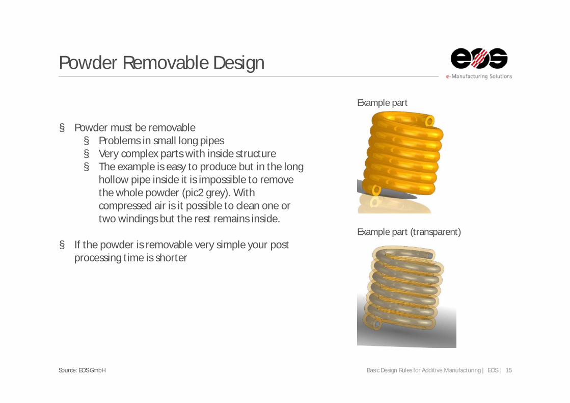
Powder Removable Design
Example part
Example part (transparent)
§ Powder must be removable§ Problems in small long pipes§ Very complex parts with inside structure§ The example is easy to produce but in the long
hollow pipe inside it is impossible to remove the whole powder (pic2 grey). With compressed air is it possible to clean one or two windings but the rest remains inside.
§ If the powder is removable very simple your post processing time is shorter

Basic Design Rules for Additive Manufacturing | EOS | 16Source: EOS GmbH
Data Format
Rough triangulation | fine triangulation
§ The interchange format for RP technologies is STL
§ The file describe a surface by triangles
§ The file size and detail resolution is depending on the number of triangles
§ Square-cut surfaces are easy to describe exact pic1. For freeform or round shaped parts you need a lot of triangles pic 2+3
§ A guide value for plastic parts is:§ deviation tolerance: 0.01 mm§ angle tolerance: 2°
This presentation may contain confidential and/or privileged information.Any unauthorized copying, disclosure or distribution of the material in this document is strictly forbidden.
For further question please contact [email protected]