adding physical like reaction effects to skeleton-based
TRANSCRIPT
HAL Id: hal-01126420https://hal.archives-ouvertes.fr/hal-01126420
Submitted on 3 Apr 2017
HAL is a multi-disciplinary open accessarchive for the deposit and dissemination of sci-entific research documents, whether they are pub-lished or not. The documents may come fromteaching and research institutions in France orabroad, or from public or private research centers.
L’archive ouverte pluridisciplinaire HAL, estdestinée au dépôt et à la diffusion de documentsscientifiques de niveau recherche, publiés ou non,émanant des établissements d’enseignement et derecherche français ou étrangers, des laboratoirespublics ou privés.
Adding physical like reaction effects to skeleton-basedanimations using controllable pendulums
Ahmad Abdul Karim, Thibaut Gaudin, Alexandre Meyer, Axel Buendia,Saïda Bouakaz
To cite this version:Ahmad Abdul Karim, Thibaut Gaudin, Alexandre Meyer, Axel Buendia, Saïda Bouakaz. Adding phys-ical like reaction effects to skeleton-based animations using controllable pendulums. Lecture Notes inComputer Science, Springer, 2011, Transactions on edutainment VI, 6758, pp.111-121. �10.1007/978-3-642-22639-7_12�. �hal-01126420�
Adding physical like reaction effects toskeleton-based animations using controllable
pendulums
Ahmad Abdul Karim1,2, Thibaut Gaudin2, Alexandre Meyer1, AxelBuendia2,3, and Saida Bouakaz1
1 Universite de Lyon, CNRSUniversite Lyon 1, LIRIS, UMR5205, F-69622, France
2 Spir.Ops Artificial Intelligence, Paris, France3 CNAM − CEDRIC, 292, rue St Martin, 75003 Paris, France
Abstract. We propose a system capable in real time of adding control-lable and plausible oscillating physical like reaction effects in responseto external forces (perturbations). These oscillating effects may be usedto modify a motion or to customize it in a cartoon like way. The core ofour system is based on several connected 3D pendulums with a propa-gating reaction. These pendulums always return to a preferred directionthat can be fixed in advance or can be modified during the motion byexternal predefined data (such as keyframe). Our pendulums are fullycontrollable, concerning reaction time and damping, and the results arecompletely deterministic. They are easy to implement, even without anyprior knowledge of physical simulations. Our system is applicable onarticulated body with predefined motion data (manually set or captured)or procedural animation.
1 Introduction
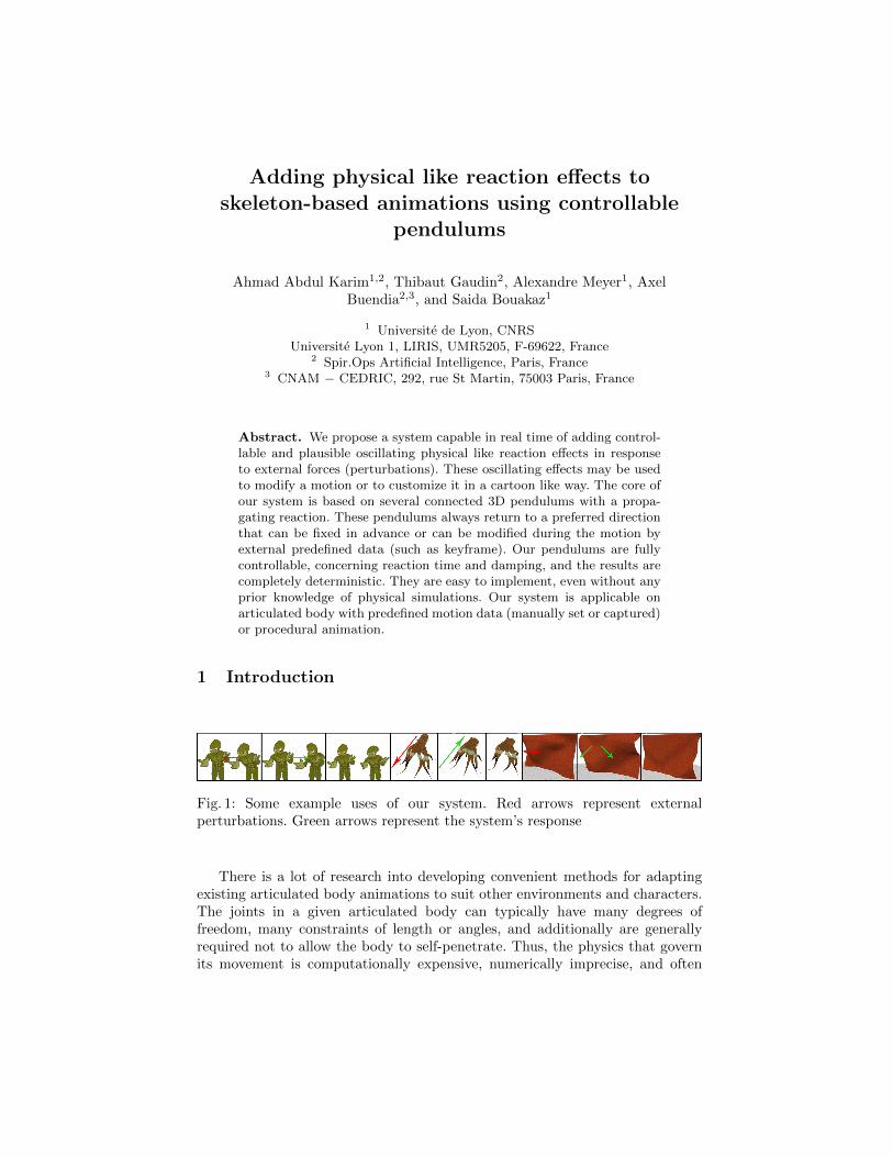
Fig. 1: Some example uses of our system. Red arrows represent externalperturbations. Green arrows represent the system’s response
There is a lot of research into developing convenient methods for adaptingexisting articulated body animations to suit other environments and characters.The joints in a given articulated body can typically have many degrees offreedom, many constraints of length or angles, and additionally are generallyrequired not to allow the body to self-penetrate. Thus, the physics that governits movement is computationally expensive, numerically imprecise, and often

difficult to predict and to control. A recent survey by Welbergen et al. [15]gives a good overview of the different methods and paradigms used and mostimportantly the trade offs between animation control and motion naturalness. Inthis context, there is a crucial demand for real-time methods providing physicallyplausible, but controllable effects [3].
We propose an original system, to our knowledge, that adds physical likereaction effects to any skeleton-based object, in real-time with a full user controlusing our 3D pendulums. The effects we seek to obtain are based on dampedoscillatory motions that propagate through an articulated chain. The effect maybe visually plausible like a rope moving in the wind, or a body reacting toexternal forces. They may also be made more cartoonish which is shown in theaccompanied video by giving a dancing like effect. In our system each bone ofthe articulated body is animated by a 3D pendulum. The pendulum is guidedby a spring-damper that pulls it toward a user-definable target direction. Ourapproach has two objectives. Firstly, we ensure body length constraint betweenany two joints by only working on the angle between the bodies. Secondly, wemake a predictable real-time system in which we can control the reaction timeto reach a user-defined direction and also the regime (critical or underdamped)of the oscillations around this direction. Our pendulums have three degreesof control: reaction time, damping and target direction. This concept of 3Dpendulums may be applicable in a multitude of scenarios with some of themillustrated in Figure 1. We must emphasize that our system is better suited foracyclic bodies and that we do not address the balancing problem in the case ofthe biped example. Our system is really easy to implement, as we will see insection 3, with no need for a full physics simulation, nor any kind of complexcalculations (like the inertia matrix). The mesh of the 3D model is animatedwith the classical linear blend skinning technique [8].
2 Related Work
Our pendulums oscillate visually like real 3D pendulums by computing theirmovements with a mass-spring approach. A mass-spring approach is a verysimple way to simulate physics-based animation [13], as it offers an intuitiveand flexible means of modeling a mechanical system. In Pixar’s movie WALL-E[10], they used a mass-spring system in a derived fashion to animate large crowdsof humans and robots in a believable way.
Editing the motion of an articulated body (producing or modifying an ex-isting animation) is an important topic in computer animation. For instance,some methods aim at warping the time of an existing motion [9], or combin-ing/blending existing motions (often represented in an animation graph) [14].Others propose the use of signal processing tools to modify animations [4].
Parallel of these approaches, an important aspect is to add physical reactionsto animations, like blending an existing motion with a physical response [2].Zordan et al. in [18, 17] use a Proportional-Derivative (PD) controller to drivethe dynamic body motion toward a re-entry in motion capture data. Our method

may be related to a PD controller, and also to the MRAC controller that usesthe Adaptive Control proposed by [12] and used in [11]. All of these controllersare like our pendulum bringing a bone to a preferred direction but we differin several essential ways. Firstly, the other methods always try to return toa preferred direction (or position), even if there is no external perturbations.This introduces a delay in the produced animation between the target pose(keyframe or motion capture data) and the response of the PD controller (asseen in [19]). On the other hand, our system is a superimposed layer over themotion data and only reacts when there is an external perturbation. Our systemplays exactly the motion data with no delay, and only adds the reaction effectswhen needed. Another difference is the controllability; our system is designed tobe temporally controlled (control over the reaction time). Temporal control in thecase of the PD controller is hard to achieve and demands some hand tuning of thegain constants. In [1] they show the ability to temporally control PD controllers(using adaptive calculation of the gain constants), but it involves some heavycalculations of the inertia matrix of each joint on each keyframe, with specificcalculations in the case of an external perturbation (calculating the re-entrykey frame). Finally, all the mentioned controllers are always critically damped.On the other hand, our pendulums can be critically damped or underdampedwhile maintaining the temporal control. An MRAC controller is designed to betemporally controlled but it calculates and adapts its gain constants on eachframe using forces and torque calculations. Our pendulums do not need anyadaptive pass once the user sets the reaction time and damping. Additionally,they can be modified in real time.
We differ from other systems of skeleton-driven deformations like [5] in thatwe concentrate only on deforming the skeleton of the articulated body, withoutany specific treatment to the mesh. Our mesh is animated by the classicallinear blend skinning [8]. With no intention to compete against realistic fabricsimulation seen in [16], we show a rigid tissue represented by a tree of bonesanimated by our approach with a large time-step and controllable computation.
3 3D pendulums
In our system, a bone of an articulated body is animated as a pendulum witha configurable target direction as illustrated in Figure 2(a). A pendulum is ananchored bar, with a fixed length L, attracted to its target direction by a spring.This spring pulls the pendulum toward this direction (described in Section 3.1).This idea allows the system to easily add plausible oscillations to any animationwith a temporal control (explained in Section 3.2). In Section 3.3 and 3.4 wepresent our linear algorithm that deals with a tree of pendulums or a skeleton,by propagating the motion of a single pendulum to its father and sons.
3.1 3D pendulum principle
We design a pendulum−→V as a rotating bar attracted to its preferred direction
by two springs: one spring on each 2D plane XY and ZY as illustrated in

Anchor
Mass
L
Another Preferred
Direction
Preferred Direction (Vertical)
(a)
Y
Z
X
3D Pendulum
O
=
=
= L
Preferred Direction (Vertical)
(b)
Fig. 2: (a) 3D pendulum (b) A 3D pendulum composed of two 2D pendulumswith Y as their preferred direction
Figure 2(b). We choose this scheme with two springs instead of one springto avoid spiral rotation motion around the target direction. The computationof pendulum
−→V motion is done using its projections
−−→VXY ,
−−→VZY independently.
During the motion, after calculating the two new spring positions in 2D−−→VXY
and−−→VZY , the 3D position
−→V is obtained by combining them and ensuring that
‖−→V ‖ = ‖−−→VXY ‖ = ‖−−→VZY ‖ = L. In the current implementation we omit the twist
component around the axe of the 3D pendulum−→V which is the third degree of
freedom, we plan to add it in a future work. It is interesting to notice that byusing the target direction
−−→−Y , we can give the impression of gravity that alwayspulls the bodies toward the ground.
3.2 Time Based control for spring dampers
Let m be a mass connected to a spring with stiffness constant k. This massoscillates around a rest position x0 with a viscous damper that has a damp-ing coefficient c. Based on Newton’s second law of physics the acceleration isx = −(k(x − x0) + cx)/m where x is the current position of the mass, andx is its velocity. We integrate this motion using the Verlet scheme [13] whichwas numerically stable during our experiment described in Section 4. Giving arandom position x to the mass, it oscillates around the rest value x0, seeking tominimize the error (x−x0) until reaching zero. This oscillation depends directlyon the constants (k, c,m). In order to achieve temporal control on the springdamper movement, we use the Settling Time Ts principle. It is the time requiredfor the mass position x to reach its max amplitude inside a given error interval(See Figure 3(a)) and remains inside it. This interval is symmetrical around x0.
Ts = − ln(tolerancefraction)
ζ ∗ w0(1)
Where the tolerance fraction is the needed error interval shown in Figure 3(a),w0 is the natural frequency and ζ is the damping of the ordinary differential

equation governing a damped harmonic oscillator:
mx+ cx+ k(x− x0) = 0
orx+ 2 ∗ ζ ∗ w0 ∗ x+ w2
0 ∗ (x− x0) = 0
with
ζ =c
2mw0, w0 =
√k
m(2)
By fixing the tolerance fraction to 5% in equation (1) and by using the userprovided settling time and damping (critically damped or underdamped), thespring damper constants k and c are calculated from equation (2), achievingtotal control over the curve of the spring damper while maintaining its dynamicaspect.
Under damped
Under damped
Critical damping Starting
Needed Error
Interval
(a)
A Father
Node Target 3D
Pendulum
Direction
A
Target
Pose
3 Son
Nodes
3D
Pendulum
(b)
Fig. 3: (a) Spring oscillation under different damping (b) 3D pendulums Tree inBlack with target direction in Grey
Figure 3(a) illustrates springs oscillating under different damping values.They oscillates around their x0 until full stop, with their respective settling time.The third spring damper is a critical spring damper which converges toward x0faster than the others, and without oscillation.
3.3 Tree of 3D pendulums
The skeleton of an articulated body is a tree of connected joints (articulations).By connecting several 3D pendulums and by defining the target direction foreach one of them, the final result is a tree of pendulums that map the articulatedstructure, as shown in Figure 3(b). Some of the 3D pendulums act as a fathernode for several others. When they move, the anchor points of their childrenmove. In order to have a visually believable reaction, these 3D pendulums need tointeract with each other. We define two strategies used in conjunction to achieve

this goal: Father Pursuit strategy and Son Pursuit strategy. In the accompanyingvideo we show the similarities between the motion of a chain of pendulums fully-physically simulated and our chain of 3D pendulums that incorporate thesestrategies. For simplicity, these strategies will be described in a 2D plane.
3.3.1 Father Pursuit Strategy. The objective of this strategy is to propa-gate the motion of the father 3D pendulum toward its children, thus they needto incorporate this movement in their own motion. Figure 4(a) illustrates twoconnected pendulums PA,PB , A,B are the positions of each mass, LA,LB arethe lengths of the bars, and θA,θB are the errors that each pendulum seeks tominimize. In this example the preferred direction of the pendulums are identical(the dashed -
−→Y ).
The update system is a top-down system scheme, starting from the anchortoward the leaf. First, on time t1 (in black) the error that we try to minimize isθA1 in PA and θB1 in PB . Now, on time t2 (in red):
1. PA moves, its spring damper tries to minimize the error, and has a newposition A2.
2. PB : the angle εAB between the two vectors−−−→B1A1 and
−−−→B1A2 is added to its
own error, αB = θB1 + εAB .3. PB : letting the spring damper integrate its equations, we obtain a new angle
value θB2 which contains the new pursuit error.4. PB : based on LB the new position B2 (in blue) is calculated.
Y
Anchor
X
Anchor
Z
(a)
Perturbation
Anchor Anchor
(b)
Fig. 4: (a) Father Pursuit Strategy (b) Son Pursuit strategy
Without this process, the new position of PB would have been B3 (in green),which is not correct and would have produced a non-logical disconnected motion.This Father Pursuit process is extended to every pendulum in the chain. A thirdpendulum PC follows the motion of its father PB , and so on. By extending thisprocess in 3D we have a totally plausible physical chain of 3D pendulums (asseen in the accompanying video). Each one reacting to its father’s movementwhile oscillating around its target direction.

3.3.2 Son Pursuit Strategy. The objective of this strategy is to reflect theperturbation that can occur on the son level, to reflect it on its father. It occurswhen the mass of PB takes a perturbation as seen in Figure 4(b) (in green). Theperturbation is regarded as a change in the position, as if we only take the finalposition resulted of an impulse applied to a rigid body.
1. The perturbation induces its full impact as if the mass PB was not attached(in red).
2. PB ’s mass has two positions: B1 (the old one) and B3 (the new one).Inverting the previously detailed computation of the father induced errorεAB , we calculate the child error εBA, the angle between
−−−→A1B3 and
−−−→A1B1
and adding it to θB1, we obtain αB = θB1 + εBA.3. The mass of PA should follow, as it is being pulled by its son now. The new
position A3 is calculated easily by choosing on the line A1B3 the point A3where ‖A1B1‖ = ‖A3B3‖.
4. This process propagates toward the anchor.5. The new positions are recalculated based on the fixed anchor position.
With this scheme, all the errors that the spring dampers need to minimizebecause of a perturbation are calculated in a bottom-up way starting from theson that took the perturbation toward the anchor.
3.3.3 Final workflow. In a tree of pendulums, calculation cycles may occurwhen two nodes are influencing each others in an endless loop (father influencingits son, then the son influencing its father, and so on.). To avoid these kinds ofloops, we use an update system inspired by Featherstone’s divide and conqueralgorithm [6, 7]. This algorithm eliminate any cyclic calculation problems andbreaks the computation into two main linear passes. The first is a bottom-uppass through the articulated body tree, and the second is carried out from thetop to the bottom. We adopt this paradigm completely. Only the calculationsdiffer, as listed below:
1. For each 3D pendulum perturbed in the tree: resolve this perturbation byapplying it on its mass then calculate the errors ε in a bottom-up iterationtoward its ancestors according to the Son Pursuit strategy.
2. For each father 3D pendulum integrate all the children errors (ε1,ε2 etc.) toits own error θ.
3. Start the standard top-down pass starting from the anchor toward the leafaccording to the Father Pursuit strategy.
In the previous step 2, there are many ways to calculate the integration:
– Summing up all the perturbation errors coming from its children: it is themethod used to produce all of our results. It is the simplest method, and theone we chose after testing.
– Calculating an average: the father node will be perturbed in the same direc-tion as the previous method, but with less amplitude. It is useful when theapplication decides that the father should be less affected by its children.

– Doing a weighted average based on:• The Mass: the heavier son has more influence on its father.• The importance of each branch: assigning predefined priorities on the
children.
We can imagine many other possibilities based on a specific application’s needs.Our system is quite easy to implement and the actual calculations in eachstrategy require only basic knowledge of 3D vector math. No prior knowledge ofphysics systems is required; we do not compute the inertia matrix nor we usethe notion of force. At the same time we can use physics principles to enhancethe end result like in the case of the father pendulum integrating its children’serrors based on the inertia matrix.
3.4 3D model Skeleton Vs. 3D pendulums tree
In the following section we demonstrate our system with skinned 3D models,using a predefined skeleton to construct the pendulums tree. Starting from thebind pose (rest pose) of the skeleton, we create a 3D pendulum for each skeletalconnection (bone) with the same length and with its preferred rest directioncalculated from the bone rest pose orientation. By maintaining the hierarchy ofthe base skeleton, we have a pendulums tree that maps this skeleton perfectly.While playing motion data, we modify the target direction of each correspondingpendulum, mimicking the base animation exactly. If the 3D pendulums start toreact to an external perturbation, each of the 3D pendulums orientation andposition is applied to its corresponding bone.
4 Applications and Results
In this section, we present several ways to use the 3D pendulums tree: addingphysical effects to lifeless models like an octopus, modifying pre-defined mo-tion data with physics reactions, and anecdotally a cloth simulation (which isnormally a closed-loop problem). In all cases, the pendulum’s reaction time,damping, and target direction is totally controllable. The results were computedon an Intel Core 2 Duo 2GHz, 2 GB RAM, with an ATI X1400, 256 MB. Ourexperimentation does not manage collisions, but we can easily imagine a systemthat creates an impulse (change in the position) on each 3D pendulum to counterany penetrations that occur.
4.1 Adding physical reaction effects to any skeleton-based bodies
In Figure 5, we use our system on a lifeless octopus model. By adding some simpleprocedural animation to its tentacles (pulling only the root node of each tentacletoward the center at random intervals) the rest of the model reacts in a passiveway, modifying the animation and adding plausible physics effects. The octopusmodel consists of 150 joints and the computation time of our superimposedphysical effects is only 0.3 ms.

1 2 3
2
4 5
2
6
2
Fig. 5: From top left: [1] the model with its 3D pendulums, [2] rest pose, [3] wepull all the tentacles toward the center, [4] reacting, [5] tentacles overshooting(underdamped regime), [6] return to rest pose
We can also use our system on animated models. In that case on each frame,the motion data takes control of the skeleton changing the preferred direction ofeach pendulums. With no external perturbations, the 3D pendulums rigorouslyfollow the animation data. When an external perturbation occurs, our systemreacts to this while continuously trying to return to the desired target pose.With such a technique, our system adds plausible physical reaction effects topredefined animation data, as a superimposed animation layer. These reactionscan furthermore be customized by making a section of the body more rigid, moreflexible, changing the reaction time, or tuning the damping. This gives the enduser a powerful tool to modulate the reaction of the body in a very easy andintuitive way.
Fig. 6: From top Left: [1] Original (on the left) and our simulated articulatedbody (on the right), [2] Two perturbations, [3] to [5] Reaction and returning tothe original keyfarme
By playing only the animation data on our test machine, for the previousmodel in Figure 6 with 92 joints, the average computation time for each frameis 0.06 ms. When playing the same animation using our pendulums and twoperturbations, the computation time rises to an average of 0.46 ms, which staysnegligible. This added cost is the result of reading the motion capture data inorder to change the pendulum’s target direction, integrating the perturbation,and then performing the main integration (as previously described).
4.2 Cloth Simulation
Although cloth is a closed loop problem, we are capable of giving the impressionof an animated cloth by simply creating several vertical 3D pendulums that cover

Horizontal 3D
Pendulums:
Child
Vertical 3D
Pendulums:
Father
(a) (b)
Fig. 7: (a) A cloth represented as a tree of pendulums (b) Cloth being pulled inthe middle with a visual representation of the 3D pendulums
the cloth, plus attaching several horizontal 3D pendulums to each vertical one(one vertical is shown in Figure 7(a)). By doing a weighted average between thepositions of all horizontal pendulums activated by their vertical father, weightedbased on the distance between each horizontal pendulum and its vertical father,we compute the final cloth position. This results in a fully reactive cloth, withoutany tearing problems, that maintains its horizontal and vertical dimensions,while giving total control over the reaction time. We are not aiming to competeagainst more general, visually and physically accurate cloth simulators that arebetter suited to simulate actual human cloth, for example. We are just proposinga less sophisticated, but stable and relatively fast method that can plausiblysimulate the motion of reactive cloth. In Figure 7(b), an external perturbation isapplied to the middle three vertical pendulums. In order to optimize calculationtime, those three vertical pendulums are the only ones actively being simulated(with the horizontal children of each one of them). The mesh is simulatedusing approximately 1500 3D pendulums. The average calculation time of thesependulums with the post calculations for the final cloth is around 5 ms.
5 Conclusion and Future Work
Our system is linear, straightforward, and based on simple 3D pendulums. Itis capable of adding physical like reaction effects to skeleton-based body veryeasily. Additionally it is highly customizable: we can control reaction time, targetdirection and damping of the motion. The current system does not enforceangular constraints. We need to incorporate them into our future work in orderto simulate real-life joint constraints that exists in most skeleton-based bodies. Inaddition to this, we are investigating coupling the system with a balance solver.This work would provide a body with the ability to actively work to maintainits balance, in opposition to the passive reactions described in this paper. Oursystem could also be used to mimic hair, which is an acyclic system and fitsneatly in the domain that the 3D pendulums system can simulate.

References
1. Allen, B., Chu, D., Shapiro, A., Faloutsos, P.: On the beat!: timing and tensionfor dynamic characters. In: Proceedings of the ACM SIGGRAPH/Eurographicssymposium on Computer animation (2007)
2. Arikan, O., Forsyth, D.A., O’Brien, J.F.: Pushing people around. In: Proceedingsof the ACM SIGGRAPH/Eurographics symposium on Computer animation (2005)
3. Barzel, R., Hughes, J.F., Wood, D.N.: Plausible motion simulation for computergraphics animation. In: Proceedings of the Eurographics workshop on Computeranimation and simulation (1996)
4. Bruderlin, A., Williams, L.: Motion signal processing. In: Proceedings of the annualconference on Computer Graphics & Interactive Techniques. SIGGRAPH (1995)
5. Capell, S., Green, S., Curless, B., Duchamp, T., Popovic, Z.: Interactive skeleton-driven dynamic deformations. In: Proceedings of 29th annual conference onComputerGraphics&InteractiveTechniques. SIGGRAPH (2002)
6. Featherstone, R.: A divide-and-conquer articulated body algorithm for parallelo(log(n)) calculation of rigid body dynamics. part 1:basic algorithm (1999)
7. Featherstone, R.: A divide-and-conquer articulated-body algorithm for parallelo(log(n)) calculation of rigid-body dynamics. part 2:trees,loops,& accuracy (1999)
8. Gain, J., Bechmann, D.: A survey of spatial deformation from a user-centeredperspective. ACM Trans. Graph. 27, 107:1–107:21 (November 2008)
9. Hsu, E., da Silva, M., Popovic, J.: Guided time warping for motion editing.In: Proceedings of the ACM SIGGRAPH/Eurographics symposium on Computeranimation (2007)
10. Kanyuk, P.: Brain springs: Fast physics for large crowds in wall-e. IEEE ComputerGraphics and Applications 29, 19–25 (2009)
11. Kokkevis, E., Metaxas, D., Badler, N.I.: User-controlled physics-based animationfor articulated figures. In: Proceedings of the Computer Animation (1996)
12. Landau, Y.D.: Adaptive control : the model reference approach / Yoan D. Landau.Dekker, New York : (1979)
13. Muller, M., Stam, J., James, D., Thurey, N.: Real time physics: class notes. In:SIGGRAPH ’08: ACM SIGGRAPH 2008 classes. pp. 1–90. ACM (2008)
14. Reitsma, P.S.A., Pollard, N.S.: Evaluating motion graphs for character animation.ACM Trans. Graph. 26 (October 2007)
15. van, H.W., van, B.B., Egges, A., Ruttkay, Z., Overmars, M.H.: Real time characteranimation: A trade-off between naturalness and control. In: Eurographics (2009)
16. Volino, P., Magnenat Thalmann, N., Faure, F.: A simple approach to nonlineartensile stiffness for accurate cloth simulation. ACM Transaction on Graphics (2009)
17. Zordan, V., Macchietto, A., Medina, J., Soriano, M., Wu, C.C.: Interactive dynamicresponse for games. In: Sandbox: Proceedings of the ACM SIGGRAPH symposiumon Video games (2007)
18. Zordan, V., Majkowska, A., Chiu, B., Fast, M.: Dynamic response for motioncapture animation. In: ACM SIGGRAPH 2005 Papers (2005)
19. Zordan, V.B., Hodgins, J.K.: Motion capture-driven simulations that hit and react.In: Proceedings of the ACM SIGGRAPH/Eurographics Symposium on Computeranimation (2002)