adding a catch can to a 2014 z51 & 2017 grand sport exiting air from the oil tank is passed...
TRANSCRIPT

Copyright by WA Technology, LLC [email protected] Page 1
W A Technology
Adding a Catch Can to a 2014 Z51 & 2017 Grand Sport
The addition of a catch can to a Grand Sport is presented first. Followed with the more detailed description provided for the install on our 2014 Z51 in our first PDF for those that want additional info. At the end of this Picture/Text Install document is an Appendix with extra related material if interested.
The Grand Sport has different PCV hoses than the dry sump in the 2014 Z51. Was trying to define just what they do so I was confident the addition of a Catch Can would NOT cause any harm and perhaps how effective it might be.
I’ll first cover the differences, a test performed and deduction defining, at least at idle, the source of the clean air that must enter the crankcase so it can exit with the purged oil residue and combustion products through the PCV system.
PCV Systems:
In the 1960’s, before the EPA dictated PCV (Positive Crankcase Ventilation) systems be used to ingest and combust the blowby past the piston rings, oil mist, oil drops and oil vapor burned after hitting the hot pistons, etc. cars employed “road draft tubes.” Recall the one on my’56 small block V8 Chevy. It consisted of a soup can size container filled with steel wool that was located in the lifter valley under the intake manifold. It had a ~3/4 inch diameter tube attached that went from the can and exited near the bottom of the oil pan. When the car was moving all the blowby and other “stuff” in the crankcase came out in the atmosphere. If you burned oil, “smoke” would come out from under the car. Not good for the environment! Today PCV systems suck that crankcase “stuff” into the intake manifold so it can be burned in the combustion chamber.
Catch Can:
In short, a “Catch Can” catches and collects some of that crankcase “stuff” before it goes into the intake manifold. Once there, along with air, it flows past the very hot intake valves where in bakes on the hot valve stem and valve back. That baked oil and “stuff” is called “coking.” With a DI engine, like the LT1 and LT4 there is no gasoline passing over the intake valves with the air and oil as it did in the C6 and prior Vettes. In those engines with port injection or carburetors, gasoline, with additives, was able to clean off this “stuff” before it could bake on the back of the intake valves.
However, the material the “Catch Can” collects MUST be frequently removed (every few thousand miles,) discarded, or it could cause problems. GM and the EPA are not going to allow such a device to be added if there is not a guarantee it will be properly maintained. Since many don’t even monitor and correct their engine oil level, etc, as is recommended, that cannot be assured.

Copyright by WA Technology, LLC [email protected] Page 2
Enter the “Catch Can”
A “catch can” has been used for a number
of years to minimize the crankcase blow-
by and oil mist from entering the intake. In
race cars the concern about this “stuff”
entering the intake is not the long term
“coking” or contamination but the inferior
performance caused by this it mixing with
the air fuel mixture. It does burn, but not
as uniform and affects performance to
some degree.
Some of the early “cans” were very
simple, just allowing the
crankcase vapors to condense
before being sent on to the intake.
For cars used as daily drivers the
newer designs include a number
of improved features. The picture
upper right is the E2 model I
purchased from Elite Engineering.
On the left is a schematic of the
E2 from their website. It simply
replaces the existing hose from
the crankcase to the Intake. The
inlet on the top of the “can” takes
the vapors and residual from the
crankcase and before it goes
directly to the intake hose barb, as it does in the stock LT1, it passes through
stainless ribbon media as shown. This allows oil vapors to agglomerate into
large drops and pass through what they call an “internal diffuser.” It is a
perforated plate that retains the stainless media. They include a “vacuum lip” to
stop the flow from immediately going to the exit ports located near the top of the
can. This slows the flow and the oil particles collect in the bottom of the can.
There are two exit ports. One can exit just connects to the existing hose barb in
the intake manifold. The other requires a hole to be drilled in the air intake duct
ahead of the throttle body.
I decided not to use the second exit for two reasons. First, after considering the
way I drive the car, not tracking, its none-supercharged and my spurts at WOT
are short in duration, it didn’t appear the second line was really needed. The
second reason is I am still trying to fully understand is when the pressure in the
intake manifold side of the throttle body is higher than in the duct before the
throttle body such that the higher pressure in the crankcase would have a
preference to go in that line. One explanation is the reversion pressure pulses in

Copyright by WA Technology, LLC [email protected] Page 3
the intake manifold that occur. However even at WOT the average pressure is
still lower in the manifold than in the air duct before the throttle body! It must be
for air to flow in that direction! Perhaps because of the reverse pressure spikes
from the manifold to the intake tube, that is when outflow from the “catch can”
would preferentially go through that added line. In ~4 years I have not seen
evidence that adding that line is a significant benefit in my situation! See
attached Appendix for information about the pressures related to this issue.
Also, the car can be converted back to stock by simply removing the Catch Can
and lines and replacing the OEM PCV hose that were removed! In fact, did that when I sold the 2014 Z51 so the “Can” could be put on the Grand Sport!
Clean Oil Separator:
The “catch can” takes care of the oil residual from the PCV system but there is
one more oil contamination issue to consider for the 2014 Z51 dry sump engine.
With that dry sump engine a scavenge oil pump attempts to remove all the oil
from the crankcase to an external tank. To accomplish this, this pumps must
also pull in air. This oil/air mixture is brought to the external tank. However only
oil not air-entrained oil must be returned to the
engine, via an oil delivery pump. Therefore
this oil tank is internally designed to separate
the air. The “burped” air, as it is sometimes
referred to, is delivered back to the air intake.
In the 2014 LT1 dry sump enters after the air
cleaner. This air may contain a small amount
of oil mist. This mist is carried with the air and
is ingested by the engine. The amount of oil
mist can be minimized. Looking at the “clean
oil separator” construction, it functions in a
similar way to the “catch can.” The exiting air from the oil tank is passed through
media in the “oil separator” that replaces the oil inlet cap. As shown in the above
picture, this cap replacement is higher and if disassembled contains similar
media as the “catch can.” The air and oil mist enters the bottom of the can and
the mist can agglomerate into oil droplets that fall back into the tank. It has to be
removed when adding oil, at which point it can also be disassembled by
unscrewing the outer shell and the parts cleaned.
For the Grand Sport, there is not a need for the Clean Side Oil Separator as there
is not a line from the dry sump tank to the air inlet tube. That burped air is
probably routed, some way, back to the crankcase via hoses going into one of the
valve covers.
A test I made with results presented, validates what one catch can manufacturer
stated, that the single line going from the air intake tube to the dry sump tank is
bringing in the needed clean air to the PCV system. Therefore the burped air
issue is probably managed by the hoses and valves to the engine valve covers.

Copyright by WA Technology, LLC [email protected] Page 4
Photo Sequence
INSTALL CATCH CAN ON 2017 GRAND SPORT
Before installing a “Catch Can” in the Grand Sport I wanted to define the differences from
the 2014 Z51 in the lines going from the engine to the dry sump tank. The need was
reinforced by recent comments from Tadge Juechter, the Corvette Chief Engineer (see
Appendix) of changes made in dry sump systems. One key difference is the 2014 Z51 dry
sump had two lines going to the air intake tube. One to bring clean air into the crackcase
for the PCV system and the other to take burped air from the dry sump tank to the air
intake tube. The Grand Sport only has one. First question, what is that line for?
Pic below shows the lines coming from the engine to the dry sump tank and the one
going to the air intake tube. Following that pic is a comment from a catch can producer
and our test result that indicates line “FA” brings Fresh Air from the air intake tube after
the air filter into the dry sump tank. Still have no idea what line “L” does. It goes from a
fitting on the front of the engine to somewhere behind the engine that is not visible. May
or may not have anything to do with the PCV system!
Line VC1 goes from the driver’s side valve cover to the small auxiliary dry sump tank that
is attached to the large tank. Line VC2 & VC2a go from the passenger side valve cover to
the top of the main dry sump tank! What all those lines carry and when is not clear! The
oil/air scavenge pump probably provides a small vacuum in the crackcase so the
pressures involved that dictate how air, air carrying crackcase “stuff” are small and the
paths cannot be deduced from the info available. I’m sure GM has done the best job
possible of designing the PCV system to minimize “coking.”

Copyright by WA Technology, LLC [email protected] Page 5
The Grand Sport has essentially the same
PCV valve/hose arrangement as my 2014 Z51
(pic right.) It has a short PCV hose that goes
to a passage to the intake manifold in a
similar place as the 2014 C7 Z51.
I was catching and discarding about an ounce
of “stuff” in the “Catch Can” every 1000
miles. An ounce that was not baking on the
back of the intake valves. Initial results show
the reduction in oil flowing through the Grand
Sport PCV hose is significant!
The 2014 Z51 had two hoses going to the
air inlet tube, one to take fresh air into
the crankcase, the other for burped air
from the dry sump tank. The Grand
Sport only has one. What does it do?
A catch can manufacturer replied to that
question I asked on a forum. He said it
was to bring air into the dry sump tank
for the PCV system.
Hmm, then what about the burped air,
where does it go. Devised a test using a
vacuum gauge to validate the comment.
Connected a vacuum/pressure gauge to
outlet from the dry sump tank that goes to the
hose attached to the air intake tube. With the
engine running, was there air flow coming out
causing pressure and indicating the line is for
transporting burped air to the intake tube?
Or was there a vacuum indicating it would be
pulling in clean air to replace the air that was
being pulled, with crankcase “stuff,” through
the PCV valve and hose and entering the
intake manifold?
The answer, it was a slight vacuum when
operating at a high cold engine idle. This
validated the catch can manufacture who said
that line was the source for fresh air!
Copyright by WA Technology, LLC [email protected] Page 6
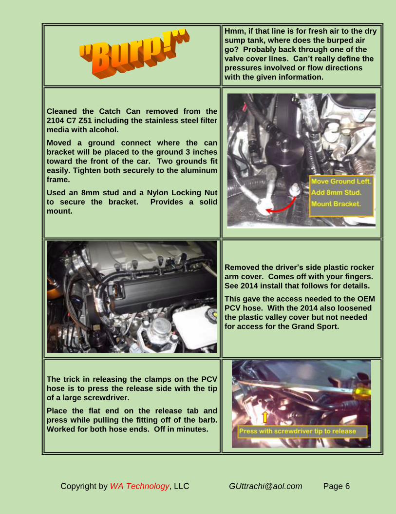
Hmm, if that line is for fresh air to the dry
sump tank, where does the burped air
go? Probably back through one of the
valve cover lines. Can’t really define the
pressures involved or flow directions
with the given information.
Cleaned the Catch Can removed from the
2104 C7 Z51 including the stainless steel filter
media with alcohol.
Moved a ground connect where the can
bracket will be placed to the ground 3 inches
toward the front of the car. Two grounds fit
easily. Tighten both securely to the aluminum
frame.
Used an 8mm stud and a Nylon Locking Nut
to secure the bracket. Provides a solid
mount.
Removed the driver’s side plastic rocker
arm cover. Comes off with your fingers.
See 2014 install that follows for details.
This gave the access needed to the OEM
PCV hose. With the 2014 also loosened
the plastic valley cover but not needed
for access for the Grand Sport.
The trick in releasing the clamps on the PCV
hose is to press the release side with the tip
of a large screwdriver.
Place the flat end on the release tab and
press while pulling the fitting off of the barb.
Worked for both hose ends. Off in minutes.

Copyright by WA Technology, LLC [email protected] Page 7
Though I might have to use a longer hose
than on the 2014 but the lengths were
perfect.
Constant tension hose clamps come with
the Elite “Can.” Installed it in the correct
area before putting on the barb and just
pushed on with enough force to have the
hose fully on the hose barb.
CAPTURE RESULTS IN GRAND SPORT
With limited data in two checks it appears the
new PCV system has accomplished a
significant reduction in oil going from the
crackcase to the intake manifold. It is still
captured in the “can” but instead of 1 oz/1000
miles, in two checks it collected only 0.25
oz/1000 miles. A 4 fold reduction.
Still better to collect that ¼ ounce/1000 miles
than have it go into the intake manifold and
bake on the hot intake valve. We’ll continue
to monitor the volume collect and update this
information if there are observed changes.
This is the short OEM PCV hose. Will
keep if needed to return to stock. Could
be accomplished in 10 minutes!
DETAILS, CATCH CAN INSTALL ON 2014 Z51
This is what Elite delivered. It consists of
their E2 “catch can,” a “clean air oil
separator,” hoses, fittings, and hose clamps.
I selected the extra cost AN end fittings since
the screw fitting connections make it easier
for cleaning (they also look cool, similar to
the branded stainless AN lines on my Pro
Street Rod!)
The billet aluminum attachment bracket is
separate and has a machined fit. It is easily
installed with the supplied screws. I used
some blue Loctite.

Copyright by WA Technology, LLC [email protected] Page 8
The “clean oil separator” has the same screw
configuration and captive large “O” ring seal
(red arrow) as the OEM oil tank cap.
I also ordered a check valve in case there
was: 1) one in the existing OEM line from
crankcase to intake (there was not) and 2) if I
was going to add the second hose later. It is
definitely needed in that case so air doesn’t
flow from the second hose to the “can”
reducing the amount of blow-by coming from
the crankcase. The check valve prevents air
passing in that direction. In my install it was
not needed or used, no reason to restrict air
movement so just matched the OEM system.
The first issue was to move the ground
connection so the catch can could be
mounted by itself on a stud placed in the
hole instead of using the exiting screw.
Since it is necessary to remove the “can”
for cleaning, no need to repeatedly screw
into the C7 aluminum frame. Note, three
ground connections are visible in this
view. I simply moved the ground to the
connection on the left (red arrow) - it fit
fine! Not sure why GM has all three
separate connections. I switched these
when the “can” was ordered and as
expected it has had no negative effect.
Brought the OEM screw to my local Ace
Hardware and purchased a short 8mm
stud and installed it into the threaded
boss on the frame using double nuts.
The nuts were then removed and the
“can” held in place with a Nylon lock nut.
The relocated ground is visible in this
picture. Even then the electrical
connection is better than it would be if
placed on top of the anodized aluminum
bracket as suggested in the install
instructions!

Copyright by WA Technology, LLC [email protected] Page 9
I removed the valve cover plastic covers and
also loosened the top plastic engine cover
studs. This helped gain access to the needed
hoses and barbs. If you have small hands (I
don’t) you may get by without removing these
items but it also allowed me to take these
pictures. Just grab the inside edge of the
cover with both hands and pull up. That is
one hand in proper position while the other
holds the camera!
This is the back side of a valve cover- plastic
cover. The top two rubber cups engage the
tops of four studs that hold down the engine
plastic cover. The bottom shows the two
hooks like attachments that slip into slots
that secure it to the engine.
After removing the valve cover- plastic
covers there are four long studs that
need to be removed. These have a 10mm
nut at the bottom. Thought this would be
easy as I just needed to use my 10mm
deep socket. However the balls on the
stud top were larger than the socket ID
near the top! Was able to wedge a 10mm
box end wrench on the nuts. Fortunately
it only required a slight turn to loosen
since that is all the room available! They
then unscrewed by hand.

Copyright by WA Technology, LLC [email protected] Page 10
These are the four posts that were
removed and where the ball on top fits
into the rubber socket in the valve cover-
plastic cover. The pic also shows the
crankcase to intake OEM PCV system
hose that was removed. Press in on the
gray tab and it releases the catch that
holds the fitting on to the barb. Press
hard while pulling. This hose has no
check valves etc.; it is simply a large ID
hose. Decided not to use the purchased
check valve since it would be somewhat
more restrictive and was not on the OEM
system. Will save it if I decide to install
the second exit hose from the can. For
now that can exit hole is blocked with a
1/4"inch NPT plug.
To remove the engine cover would
require disconnecting more than needed
for access to the hose barbs. Used a
piece of wood to wedge the front up.
Inserted the two short hose in the kit on
the two barbs where the OEM hose
shown above was removed. Left them
the original length, for now. Note I put
the clamp on prior to inserting the top
hose on the barb. That hose will go to
the “can” side outlet. It slipped on with
the clamp in position with modest force
and access issues. It would be difficult,
with my fat hands, if I tried to expand and
slip the clamp down after the hose was
placed on the barb.

Copyright by WA Technology, LLC [email protected] Page 11
The “can” fittings were installed and
aligned so the hose had a minimum
bend. I used thread sealer. The hoses
were cut to the length needed with an
anvil cutter (a single blade razor could be
used.) If you make them too long they
could rub on parts as the engine moves
when running. Measure twice and cut
once, if too short, you’re out of luck!
I installed the AN fittings on the hose and
threaded them on to the “can” fittings.
“Catch Can” Install Completed
Installing the “Clean Oil
Separator”
I removed the radiator air duct to take
these pictures and to better see the hose
connection. Four 7mm bolts hold it in
place. The right angled fitting shown in
the picture is removed the same as
others, press in on the gray button and
pull.
The long hose supplied with the kit is placed
on the hose barb in the air duct. It is then
routed through the plastic clamps where the
OEM hose was removed. Unlike the OEM
hose, which is stiff and pre-bent, it is not. But
it fits fine.

Copyright by WA Technology, LLC [email protected] Page 12
The “Clean Oil Separator is made in
several parts but comes assembled. The
plastic base screws in the same as the
original oil cap. Then there is an “O”
ring sealing the aluminum insert to the
plastic base. These were difficult to
separate in my case. In fact a Forum
comment got me to try.
This is a finished photo of the plug supplied
(right) that is placed over the barb where the
OEM hose was removed. The hose from the
air intake is placed on the barb on the
“separator.”
Note, When adding oil you need to pull the
“separator” out of the plastic holder that is
screwed into the dry sump tank.
“Clean Oil Separator” Install
Complete
Comment About the Elite Engineering Product:
Both the “catch can” and “clean oil separator” are well made and have an
excellent finish. The threaded parts fit perfectly and are easy to assemble. The
hose and clamps are fine quality. They look great, OEM and professionally
installed in the engine compartment.

Copyright by WA Technology, LLC [email protected] Page 13
Time to Check Oil Level
Accumulation and Cleaning:
Actually, been traveling so only had
about 600 miles on the Vette from the
first time I checked the accumulation.
However, had time and wanted to check
how to clean the stainless ribbon wool.
If you want an OEM type appearance,
spend the extra $26 and get the Military
AN fittings. I have the proper aluminum
AN wrench for my Street Rod where all
fuel lines are AN fittings but you can put
masking tape on an 11/16 inch wrench to
protect the finish.
As noted on the install, I moved the electrical
ground connection and installed a stud to
replace the bolt. Makes it easy to remove the
assembly. Here you can see the small
amount accumulated which is about the same
amount I removed a month after install. Only
about an ounce in ~1000 miles. But better the
ounce is removed that baking on the intake
valves! Side view shows the height of the
container that houses the ribbon like
stainless wool. It catches oil vapors and mist
and causes it to form larger drops that fall
into the bottom on the can.
This is a top view. As with all the
construction, the threads are cut
perfectly and screw precisely into the
inside machined top of the can. Very
professional. Had there been more
accumulation, would have run mineral
spirts trough the stainless ribbon to
clean it.

Copyright by WA Technology, LLC [email protected] Page 14
Cleaning the “Clean Oil Separator”
This process is straight forward. The
bottom machined aluminum baffle
unscrews from the one piece black top,
as shown left. Pour some mineral spirits
in the top over the stainless ribbon and
watch it pour from the outlet hose barb.
It will run clean quickly. When it runs out
clear it’s clean.
Mineral spirts evaporates quickly.
Checked the other day (9/17/2015) when
performing and oil change. Again about
an ounce in 1000 miles. This time use
alcohol as a cleaner. Rinsed it into the
can and dumped all into the old oil taken
to the recycling center.

Copyright by WA Technology, LLC [email protected] Page 15
APPENDIX
This appendix covers several subjects:
1. Why the need for the second “catch can” exit hose?
2. Problems with “coking” in Direct Injection Engines
Although there is some data presented I do not have the answers. If anyone takes the time to read this appendix, feel free to email your thoughts. Email address is in the footer of all pages.
Need for the Catch Can Second Outlet Hose
I have tried to define if the second outlet were attached as directed to the inlet side of the throttle body, when the pressure would be lower than in the manifold or the downstream side of the throttle body. Is the second line needed for a naturally aspirated engine? I have not
defined why but I accept since a number offer that feature it is of some benefit in some situations. But why?
The schematic left shows the pressures and locations in question. The OEM hose where the “catch can” system was added is between the crankcase, P1 and the intake manifold P3. Since our business is controlling gas through a hole (Argon for welding) I used those rather complex flow equations to define
the pressure difference P2 to P3 at wide open throttle (WOT.) Looking at the LT1, at 6500 rpm the air flow through the throttle body at WOT will be about 700 cubic feet of air per minute (CFM.) That assumes an unrealistic 100% volumetric efficiency but that is good enough for our calculations. The throttle body is 3.4 inch (87mm) diameter. If the pressure at P2 is atmospheric, 14.7 psia, then to flow 700 CFM of air through a 3.4 inch diameter hole (forgetting losses due to the throttle plate etc) would require about 0.5 psi higher P2 pressure than P3. Therefore the manifold pressure P3 would be about 14.2 psi. I also assume the crankcase pressure is positive, i.e. greater than 14.7 psia. That could be wrong depending on the dry sump oil scavenger pumps. In some racing engines they use very large pumps to create a vacuum, which can add significant hp! One report shows that a 10 psia crankcase pressure (a 4.7 psi vacuum) achieved a 15 hp increase at high rpm! It is attributed to reduced windage.
Elite, in a forum post, indicated that “…the 2nd
port is a factor anytime the throttle is opened from 2/3 to WOT by using the suction (lower pressure than in the crankcase) present upstream of the throttle body when reversion pulses in the intake manifold cancel any measurable vacuum. Then the PVC system stops evacuating and pressure builds in the crankcase possibly pushing oil vapors backwards out of the fresh side inlet allowing oil injection.” They no doubt have real pressure data so I accept their proposition. Although the P3 “average pressure” must be slightly lower than P2 too have 700 CFM flow in that direction (flow goes from high to low pressure.) However, higher pressure short pulses exist! Perhaps if tracking the car where it can be at WOT for a long time that second line is a benefit. However my WOT situations, although often frequent are for very short duration. Relative to the amount of miles I put on my daily driver the time at WOT is insignificant.
As the throttle closes from WOT the pressure in the manifold reduces and even more blow-by would go to the manifold and little, if any, to the downstream connection. A check valve would have to be put in the hose placed before the throttle body to prevent the higher P2 pressure flowing air back through the can to the lower pressure P3.
BOTTOM LINE, SECOND OUTLET HOSE
For two reasons I kept the one exit hose set-up. First, the amount of my WOT is in short bursts and a very small fraction of my driving. Frequent but not high on a percentage basis! The second reason is it can be returned to stock with little effort if, which I did when the 2014 was sold to install it on the Grand Sport!.-

Copyright by WA Technology, LLC [email protected] Page 16
Reduces Oil Residue Problems
The Stingray LT1 engine
has great performance.
One reason is the higher
compression tolerated
because of the more
efficient Direct Injection
(DI.) Similar to a diesel
engine; fuel is injected
directly in the combustion
chamber. However this
advance has a downside,
there is nothing to help
clean the oil residuals
coming from the positive
crankcase ventilation
(PCV) system. In the 1960’s blow-by past the piston rings was no longer allowed
to be vented to the atmosphere as was prior practice. This vented crankcase air
also contains fine oil mist created when the fast spinning crankshaft impacts oil
particles. Some of this fine mist is heated to high temperatures as it contacts the
hot piston. This combination of combustion products and contaminated oil is
feed back into the engine intake by what is referred to as the PCV system. A PCV
valve controls the amount allowed to enter the engine as manifold vacuum varies.
Direct Injection Causes Some Problems:
The oil residue can accumulate and bake on the back of the hot intake valves.
This is referred to as “coking.” This changes the carefully contoured passages
that promote high horsepower and smooth performance. With carbureted or port
injection the gasoline with cleaning additives, washes past the intake passage
and hits the back of the intake valve. This cleans those surfaces and minimizes
residual build-up. However with direct injection (DI) there is no gasoline to help
clean this residual and keep it from accumulating. Only air and PCV residuals
pass the valve! This is not just a Corvette problem; it has been a concern for
Ferrari, Porsche, B&W and others who have introduced high performance DI
engines before GM. The 2009 Ferrari 458 Italia’s 560 hp 4.5 liter V8 is a DI engine.
Their forum posts indicate “coking” is concern and there are discussions about
using an intake cleaning process at each oil change that employs a vapor or
liquid cleaner added to the intake with the engine running! Toyota in fact has an engine that uses DI and port injection that they use periodically to clean residue on the intake valves!
Reasons to Do Something An article in the December 2014 issue of Hot Rod magazine quotes several GM
engineers who were discussing the LT4 with the author Brandan Gillogly. John
Rydzweski, Assistant Chief Engineer for Small Block V 8’s was one of the two
engineers.

Copyright by WA Technology, LLC [email protected] Page 17
This is a quote by the author NOT one of the GM engineers who may, in fact,
disagree with the statement:
“A little bit of oil on a port-injection engine can help lubricate valves, but because the Gen 5 V8’s (all C7’s as the LT1) are Direct Injected, there’s no fuel washing the back of the intake valve. That means oil in the PCV system can end up sticking to the back of the hot intake valves impeding airflow and eventually preventing the valves from seating properly.”
This is not a simple problem that GM uniquely solved! I’m sure they did all they
could but without a long term history of how the car performs the way folks drive,
it will take time to find out.
You may recall the oil company ads that talked about the cleaning additives they
added to their gasoline:
The picture left is from Shell and shows “coking” without their cleaning additive
and a clean valve with it. The picture right shows “coking” without cleaning
additives and with varying amounts added; 1.1, 1.7 and 2.7 units. As noted, it
gets less with added amounts.
However with a DI engine the gasoline is injected directly into the combustion
chamber and the back of the valves never see it! It’s worse than no additive
since gasoline by itself is a pretty good cleaner! A DI engine doesn’t have what
we all have been experiencing for years with carburetors and port injection!
Don’t think you’re doing any cleaning of the valve backs by running the engine at
high rpm and “blowing it out” with a rich mixture! The only thing passing over
the valves will be more air and PCV blow-by!
Is it a Real Performance or a Cosmetic Issue?
A question was asked and the Chief Corvette Engineer, Tadge Juechter, who
provided this answer in July 2015 in a monthly Corvette Forum Column called “Ask Tadge”:
Question: Is there any issue known with deposit buildup on the back side of the intake valves due to not having a port injection system?

Copyright by WA Technology, LLC [email protected] Page 18
Is GM aware of, and if so do they have any plans for correction with the intake valve coking issue present in the direct injection platforms as a result of the PCV system. Many members of the community are seeing an excessive amount of oil and carbon deposit buildup on the intake valves after only 5,000-10,000 miles and worse with even higher mileage engines on the C7. While I understand the purpose of the PCV system as it relates to emissions, with the introduction of direct injection there is no longer a cleaning process in place that would be naturally present such as from a port injection system.
Tadge Answered, Quoting Exactly: “Good technical question. The short answer is: No, we have not seen any issue with deposit buildup on the back side of the intake valves due to not having a port injection system. You correctly point out that the continuous flow of clean air and gas over the intake valve tends to keep it very clean. That has been a characteristic of small block V8's for decades. Of course, appreciation of that characteristic is limited to those who disassemble their engines. Most customers are unaware. Given that all SIDI engines give up that benefit in favor of other important attributes, we did extensive testing to make sure there were no customer-observable penalties. We intently looked for unusual deposit formation during the entire Gen 5 Small Block development phase (4 years) as well as the 200,000 mile in-vehicle long term testing. We have not seen anything unusual and zero performance degradation. Granted, deposit formation on SIDI engine intake valves is greater than what is seen with PFI engines, but the Gen 5 engines are typical for SIDI engines, and in fact better than other SIDI engines we have benchmarked. So the bottom line is that we believe the carbon build up is only an internal cosmetic issue, not anything that will affect customers over the life of their cars.”
A more recent posted comment from Tadge about the PCV stem relative to what
is reported to be a “Catch Can” system recently added to the Camaro (which is
NOT what it is!) Quoting:
“The Corvette's dry sump tank looks relatively simple on the outside but the internals are really quite complex. The top third of the tank contains a PCV air/oil separation system. On the Corvette, PCV lines route from the valve covers to the air/oil separator on top of our dry sump tank. Oil from PCV air is separated and returned to the lube system through the oil tank. The PCV separation system on Camaro V8 performs a similar function except oil is returned to the engine oil pan from the PCV separator's drain back tube. The Camaro V8 PCV air/oil separator is more complex than a "catch-can" since it not only separates oil from PCV air it provides a drain back path for this oil to be reused by the lube system.
"Catch-Can" systems that do not have a drain back path for separated oil run the risk of poor oil pressure performance over time as oil is removed from the lube system.
The bottom line is that both cars use optimized engineering solutions for their lube systems based on vehicle architectural considerations.”

Copyright by WA Technology, LLC [email protected] Page 19
My view of the comments: Tadge admits there is carbon build-up, they looked for
“unusual deposits” in their 4 years of development, and found the Gen 5 is
typical of SIDI engines (which some car companies admit are a problem because
of carbon deposits) but believe the carbon build-up is a cosmetic issue and not
something that will affect customers “over the life of their cars.”
So a deposit will occur, the remaining question, is there a way to minimize it?
Tadge’s comments about the dry
sump reflect the different hose
arrangement in my Grand Sport. In
fact it does have some ability to
return some oil residue back into
the oil reservoir. However the
Grand Sport, although having
additional lines and using hoses
from the valve covers to the dry
sump tank still has a PCV hose coming from the crankcase and going to the intake manifold!
Pic left shows essentially the same
PCV (Positive Crankcase Ventilation) valve and short hose taking crankcase
fumes, burnt oil from droops and mist hitting the hot pistons etc. and “injects it in
the intake system then combusts it I the combustion chamber. That still means
this oily “stuff” passes over the backs of the hot intake valve and can cause
“coking.”
If the new system does in fact produce significantly less oil “stuff” the three
should be less in a “Catch Can” to catch! The single outlet Elite Catch Can I
added to the 2014 will do no harm.
Understand Tadge’s comment about the use of a catch can, quoting above:
"Catch-Can" systems that do not have a drain back path for separated oil run the risk of poor oil pressure performance over time as oil is removed from the lube system.”
Since many folks don’t check oil level or tire pressure as they should how could GM expect them to 1) empty a catch can so it doesn’t clog with oil and 2) be sure there is sufficient oil in the system? They can’t!
However don’t understand this part of the statement: ”..as oil is removed from the lube system.” The PCV system, by definition, removes some oil from the system and pulls it into the combustion chamber to be burned! Some oil is lost as it performs that function. All the “Catch Can” does is collect some of the oil so it can be discarded before it has a chance to bake on the intake valves. However if the collected oil is not periodically removed from the “Can” it would block the PCV function and cause engine and emissions issues.
Doubt the EPA would allow a system to be added that needs to be frequently checked, the oil collected and discarded properly to assure emissions levels are maintained!

Copyright by WA Technology, LLC [email protected]
W A Technology
Other 2017 Grand Sport & 2014 Stingray PDF’s Available:
Some 40 items discuss improvements or information about a 2017 Grand Sport
and 2014 Stingray function and/or esthetics. Some are minor and others, like the installing ceramic brake pads, include detailed install information.
Below are the PDF’s available. Click on picture (may need Ctrl pressed.) Or just copy and paste the PDF info (Blue type) into your browser. Or email me at
[email protected] and state the title desired, shown in Yellow:
Note: GS indicates the info was updated from that available for the C7 Z51 PDFs.
Rusty GS/C7 Muffler
Why the C7 muffler is rusted and a simply way to make rust turn matte black.
Bottom pic rusted, top pic treated
http://netwelding.com/Muffler_Rust.pdf
Change GS/C7 Oil
WHY change your own oil and HOW to do it
Revised, includes C7 Lifting Methods
http://netwelding.com/Changing_Oil.pdf
C7 Carbon Fiber Side Skirts
How to install side skirts with jacking information for DIY's without lifts
http://netwelding.com/Side_Skirts.pdf
C7 Carbon Fiber Splitter w/End Plates
How to install Splitter & Nylon bra fit
http://netwelding.com/CF_Splitter.pdf
C7 Removing GM Plastic Film
How To Remove The Rocker Panel Film
http://netwelding.com/Rocker_Panel_Film.pdf

Copyright by WA Technology, LLC [email protected]
GS/C7 Mirror Proximity Alarm Limit switch alarm warns when passenger mirror is
too close to door frame
http://netwelding.com/Mirror_Proximity_Alarm.pdf
Jacking Pads for GS/C7 Jacking Pads must 2 1/2 inch max OD. Made four.
Bought 2 1/2 inch OD x 2 inch high pads after installing side skirts; Bought pads right for the GS.
http://netwelding.com/Jacking_pads.pdf
GS/C7 Radar Power For C7 tapped rear fuse panel. For GS tapped mirrow
http://netwelding.com/Radar_Detector_Power.pdf
GS/C7 Belt Rattle Passenger seat belt rattles against the seat back. The
solution, add a shoulder belt pad.
http://netwelding.com/Eliminate_Rattle.pdf
Aluminum C7 Chassis and Weld Repair The C7 has an all aluminum chassis, made from 117
welded pieces
http://netwelding.com/Aluminum_Chassis.pdf
GS/C7Ceramic Brake Pads The Z51 has very dusty brakes. These pads help!
http://netwelding.com/Ceramic_Pads.pdf
GS/C7 License Plate Frame;
Must Meet South Carolina Law
http://netwelding.com/License_Plate_Frame.pdf
Manage GS/C7 Spilled Gas Protect the side of the Vette when filling up with gas
http://netwelding.com/Manage_Spilled_Gas.pdf
GS/C7 License Plate & Cargo Lights
LED license plate light & cargo area bulbs are brighter and whiter
http://netwelding.com/License_Plate_Light.pdf
GS/C7 Rear Cargo Area Rear cargo area needs storage device and rear
protector
http://netwelding.com/Rear_Cargo_Area.pdf

Copyright by WA Technology, LLC [email protected]
GS/C7 Door Panel Protector Black plastic protector added to prevent scuffing of
door when exiting
http://netwelding.com/Door_Panel_Protector.pdf
GS/C7 Improved Cup Holder A solution to the cup holder spilling under hard
braking or shape turns.
http://netwelding.com/Improved_cup_Holder.pdf
GS/C7 Wheel Chatter/Hop Why sharp, low speed turns with cold tires causes
the front tires to chatter/hop.
http://netwelding.com/Wheel_Chatter.pdf
C7 Carbon Fiber Grille Bar Install genuine carbon fiber grille bar overlay
http://netwelding.com/CF_Grille_Bar.pdf
Jacking a GS/C7 Vette Safely jacking either front only or back & front
http://netwelding.com/Jacking_A_C7.pdf
Deer Whistle Installed on GS/C7
Do they work? Plus Install Info
http://netwelding.com/Deer_Whistle.pdf
Replacing C7 Battery After using a GM type charger and showing fully
charged a voltage low, replaced battery with AGM!
http://netwelding.com/Battery_Issues.pdf
GS/C7 Window Valet
Lower Windows with FOB
Window Valet Helps 2014/2015 Latch Hatch
http://netwelding.com/Hatch_Latch.pdf
GS/C7 Splash Guards
GM offers splash guards for the C7 Corvette. An easy DIY installation. ACS Best Front Guards for GS.
http://netwelding.com/Splash_Guard.pdf
GS/C7 Blind Spot Mirror
Smaller rear and side windows cause C7 blind spots. Small "blind spot mirrors" help
http://netwelding.com/Blind_Spot.pdf

Copyright by WA Technology, LLC [email protected]
GS/C7 Skid Pad Protector
After the air dam, the aluminum "skid pad" hits
driveway ramps etc. Plastic protector helps.
http://netwelding.com/Skid_Pad_Protector.pdf
GS/C7 Wheel Locks
Wheel locks, torqued to required 100 ft-lbs, help
protect your expensive wheels from theft.
http://netwelding.com/Wheel_Locks.pdf
GS/C7 OnStar Lights
The OnStar LED's in the rear view mirror, at a quick glance, look like a police car flashing light! This is a
fix.
http://netwelding.com/OnStar_Lights.pdf
GS/C7 Skip Shift Eliminator
Skip Shift Eliminator install with suggestions on
jacking a C7.
http://netwelding.com/Skip_shift_Eliminator.pdf
C7 Catch Can & Clean Oil Separator
Direct inject engines like the LT1, are particularly subject to “coking.” What is Coking and how to
reduce the potential?
http://netwelding.com/Catch_Can.pdf
GS/C7 Round Shift Knob
A round shift knob shortens throw.
http://netwelding.com/Shift_Knob.pdf
GS/C7 Stingray Sill Plate
Stingray sill plate replaces original.
http://netwelding.com/Sill_Plate.pdf
GS/C7 Nylon Bra
Nylon Bra Stops Bugs on Front and Grill. Fits with Stage 3 Winglets
http://netwelding.com/Nylon_Bra.pdf
GS/C7 Clutch Fluid Change
Clutch fluid after 3000 miles gets dirty
http://netwelding.com/Clutch_Fluid.pdf

Copyright by WA Technology, LLC [email protected]
C7 Carbon Fiber Hood Vent
Replaces Plastic Hood Vent
http://netwelding.com/Hood_Vent.pdf
GS/C7 Cold Air Intake
Low Restriction Air Filter & Duct
http://netwelding.com/Cold_Air_Intake.pdf
Garmin GPS for GS Cubby
Garmin Mounts in GS Cubby
http://netwelding.com/GPS_In_Cubby.pdf
GS Splitter Stage 3 Winglet
Stage 3 Winglets Integrate with Spats
http://netwelding.com/Stage_3_Winglets.pdf
GS 2LT to 2.5 LT
Red Upper Dash Pad Like 3LT
http://netwelding.com/Red_Dash_Pad.pdf
Jake Emblem/Decals for GS
Jake Symbols Support GS Racing Image
http://netwelding.com/Jake_Emblems.pdf
GS Splitter Protector
Rugged Plastic Protection for Splitter
http://netwelding.com/Splitter_Protectors.pdf
GS Engine Compartment Mods
Cosmetic Additions in Engine Compartment
http://netwelding.com/Engine_Compartment.pdf
GS Vitesse Throttle Controller: Fits All C7s
Adjustable Throttle-by-Wire Control
http://netwelding.com/Throttle_Control.pdf
GS Air Dam, Functions
Why Missing from Z51, Some GS & Z06
http://netwelding.com/Air_Dam.pdf
May Be Of Interest:
Engineering a ProStreet Rod
How Our ’34 ProStreet Rod Was Designed and Built 8.2 Liter Engine, 4 Wheel Disk Brakes & Coilovers
http://netwelding.com/Engineering%20Street%20Rod%203-08.pdf