addendum, user manual, suspect vehicle bit...manual vehicle commands all vehicle commands available...
TRANSCRIPT

User Manual Addendum, Suspect Vehicle Bit
Document: 10005200152; MMI-UM029A-EN-P
Version: 00

User Manual Addendum, Suspect Vehicle Bit
10005200152 Ver. 00 MMI-UM029A-EN-P
Copyright © 2019 Rockwell Automation, Inc. Page 2 of 26
Although every effort is made to keep this document accurate and up to date, MagneMotion®
assumes no responsibility for any errors, omissions, or inaccuracies. Information that is
provided in this document is subject to change without notice. Any sample code that that is
referenced in this document or included with MagneMotion software is included for
illustration only and is, therefore, unsupported.
MagneMotion®, MagneMover®, QuickStick®, MML™, MM LITE™, and SYNC IT™ are
trademarks or registered trademarks of MagneMotion, a Rockwell Automation Company.
Rockwell Automation® is a registered trademark of Rockwell Automation, Inc. EtherNet/IP™
is a trademark of ODVA®, Inc. All other trademarks are properties of their respective
owners.
This product is protected under one or more U.S. and International patents. Additional U.S.
and International patents are pending.
Copyright © 2018 MagneMotion, Inc., a Rockwell Automation Company. All Rights
Reserved.
The information that is included in this document is proprietary or confidential to Rockwell
Automation, Inc. Any disclosure, reproduction, use, or redistribution of this information by
or to an unintended recipient is prohibited.
MagneMotion, Inc.
A Rockwell Automation Company
139 Barnum Road
Devens, MA 01434
USA
Phone: +1 978-757-9100
Fax: +1 978-757-9200
www.magnemotion.com

User Manual Addendum, Suspect Vehicle Bit
10005200152 Ver. 00 MMI-UM029A-EN-P
Copyright © 2019 Rockwell Automation, Inc. Page 3 of 26
Contents
Overview ................................................................................................................................... 5
Related Documents ................................................................................................................... 5
NCHost TCP Interface Utility User Manual Addendum .......................................................... 6
Monitoring Vehicle Status .................................................................................................. 6
Manual Vehicle Commands ................................................................................................ 7
Lock a Vehicle .............................................................................................................. 7
Unlock a Vehicle........................................................................................................... 7
Delete a Vehicle ............................................................................................................ 7
Clear Suspect Bit for a Vehicle ..................................................................................... 8
MM Configurator Utility User Manual Addendum .................................................................. 9
Vehicle Suspect Bit Configuration ..................................................................................... 9
EtherNet/IP ................................................................................................................... 9
Host Controller TCP/IP Communication Protocol User Manual Addendum ......................... 11
Host Controller to HLC Communications ........................................................................ 11
Vehicle Command (0xBF 03 04) ................................................................................ 12
HLC to Host Controller Communications ........................................................................ 14
Command Status (0xD0)............................................................................................. 15
Host Controller EtherNet/IP Communication Protocol User Manual Addendum.................. 17
Host Controller to HLC Communications ........................................................................ 17
Vehicle Command Message ....................................................................................... 18
HLC to Host Controller Communications ........................................................................ 20
MMI_vehicle_command_status .................................................................................. 21
HLC Status Codes ................................................................................................................... 23
More Information .................................................................................................................... 24
Rockwell Automation Support ............................................................................................... 25
Figures
Figure 1: NCHost TCP Interface Utility for MagneMover LITE ............................................. 6
Figure 2: NCHost – Vehicles Pane ........................................................................................... 6
Figure 3: NCHost – Manual Vehicle Commands Section ........................................................ 7
Figure 4: MagneMover LITE Configurator Utility – PLC EtherNet/IP Settings Page ............ 9
Tables
Table 1: Host Controller to HLC Commands ......................................................................... 11
Table 2: HLC to Host Controller Responses .......................................................................... 14

User Manual Addendum, Suspect Vehicle Bit
10005200152 Ver. 00 MMI-UM029A-EN-P
Copyright © 2019 Rockwell Automation, Inc. Page 4 of 26
Table 3: PLC to HLC Explicit Message Requests .................................................................. 17
Table 4: UDT Configuration for udt_MMI_vehicle_command ............................................. 18
Table 5: Message Configuration for MMI_vehicle_command ............................................. 19
Table 6: HLC to PLC Status Memory Tags............................................................................ 20
Table 7: UDT Configuration for udt_MMI_vehicle_command_status .................................. 22
Table 8: HLC Status Codes..................................................................................................... 23

User Manual Addendum, Suspect Vehicle Bit
10005200152 Ver. 00 MMI-UM029A-EN-P
Copyright © 2019 Rockwell Automation, Inc. Page 5 of 26
Overview
The Suspect Vehicle Bit identifies vehicles that are manually moved out of the control region
for that vehicle. Typically, control of the vehicle cannot be regained in this situation. Even if
control is regained, the vehicle continues to be suspect. This update provides user control of
the Suspect bit status, which allows the Suspect bit to be cleared once control of the vehicle
is regained.
This document describes the changes to the NCHost TCP Interface Utility, the MM LITE
Configurator Utility, the Host Controller TCP/IP Communication Protocol, and the Host
Controller EtherNet/IP Communication Protocol.
Related Documents
This document references the following manuals:
Host Controller TCP/IP Communication Protocol User Manual, 990000436.
Host Controller EtherNet/IP Communication Protocol User Manual, 990000437.
MagneMover LITE Configurator User Manual, 990000558.
NCHost TCP Interface Utility User Manual, 990000562.
NOTE: Distribution of this document is not controlled. Changes to the document set or the
software can be made at any time. To identify the current revisions or to obtain a
current version, contact Customer Support at +1 978-757-9102 or

User Manual Addendum, Suspect Vehicle Bit
10005200152 Ver. 00 MMI-UM029A-EN-P
Copyright © 2019 Rockwell Automation, Inc. Page 6 of 26
NCHost TCP Interface Utility User Manual Addendum
This section is an addendum to the NCHost TCP Interface Utility User Manual and describes
additions to the NCHost User Interface for vehicle commands.
Figure 1: NCHost TCP Interface Utility for MagneMover LITE
Monitoring Vehicle Status
Vehicle status is available through the Vehicles pane that is shown in Figure 1. The Vehicles
Pane can also display extended vehicle status, see Figure 2 and the Vehicles section in the
NCHost TCP Interface Utility User Manual for detailed descriptions of all items).
Figure 2: NCHost – Vehicles Pane

User Manual Addendum, Suspect Vehicle Bit
10005200152 Ver. 00 MMI-UM029A-EN-P
Copyright © 2019 Rockwell Automation, Inc. Page 7 of 26
Manual Vehicle Commands
All vehicle commands available to be sent from NCHost to the high level controller (HLC)
are in the Manual Vehicle Commands section (see Figure 3).
Figure 3: NCHost – Manual Vehicle Commands Section
Lock a Vehicle
1. Check the status of the vehicle in the Extended Vehicle Status pane to verify it is
unlocked (Lkd = N).
2. Set the Vehicle ID in the Manual Vehicle Commands to the vehicle ID.
3. Select Lock from the Vehicle Command drop-down menu.
4. Select Execute.
The vehicle locked status (Lkd) changes to Y.
Unlock a Vehicle
1. Check the status of the vehicle in the Extended Vehicle Status pane to verify it is locked
(Lkd = Y).
2. Set the Vehicle ID in the Manual Vehicle Commands to the vehicle ID.
3. Select Unlock from the Vehicle Command drop-down menu.
4. Select Execute.
The vehicle locked status (Lkd) changes to N.
Delete a Vehicle
NOTICE
Using the Delete Vehicle command to delete a vehicle that is physically
present on the transport system can cause collisions as the system no longer
accounts for that vehicle as it moves other vehicles.
1. Set the Vehicle ID in the Manual Vehicle Commands to the vehicle ID.

User Manual Addendum, Suspect Vehicle Bit
10005200152 Ver. 00 MMI-UM029A-EN-P
Copyright © 2019 Rockwell Automation, Inc. Page 8 of 26
2. Select Delete from the Vehicle Command drop-down menu.
3. Select Execute.
The HLC removes the vehicle from the vehicle status list and makes the vehicle ID
available for reuse.
Clear Suspect Bit for a Vehicle
1. Check the status of the vehicle in either the Vehicle Status or the Extended Vehicle
Status pane to verify it is suspect (Sus = Y).
2. Set the Vehicle ID in the Manual Vehicle Commands to the vehicle ID.
3. Select Clear Suspect Bit from the Vehicle Command drop-down menu.
4. Select Execute.
The vehicle suspect status (Sus) changes to N.

User Manual Addendum, Suspect Vehicle Bit
10005200152 Ver. 00 MMI-UM029A-EN-P
Copyright © 2019 Rockwell Automation, Inc. Page 9 of 26
MM Configurator Utility User Manual Addendum
This section is an addendum to the MagneMover LITE Configurator User Manual and
describes additions to the MagneMotion Configurator User Interface for support of user
control of the Suspect bit when using a PLC as the host controller.
Vehicle Suspect Bit Configuration
See Set EtherNet/IP for a PLC in the MagneMover LITE Configurator User Manual for
configuring the EtherNet/IP settings in the Node Configuration File.
When using the functionality described in this document, it must be enabled when using a
PLC to make sure that the correct tag data is pushed to the host controller. When not using
the functionality described in this document, it must be disabled when using a PLC to prevent
unexpected tag data being pushed to the host controller.
EtherNet/IP
EtherNet/IP is used to communicate with a PLC being used as a Host Controller. The
EtherNet/IP page, which is shown in Figure 4, is accessed by selecting the EtherNet/IP
category from the Configuration Tree.
Figure 4: MagneMover LITE Configurator Utility – PLC EtherNet/IP Settings Page
See the MagneMover LITE Configurator User Manual for detailed descriptions of all page
options.

User Manual Addendum, Suspect Vehicle Bit
10005200152 Ver. 00 MMI-UM029A-EN-P
Copyright © 2019 Rockwell Automation, Inc. Page 10 of 26
Use a PLC for Host Control – Select to enable PLC control of the transport system via
EtherNet/IP protocol. The default is cleared (off).
PLC IP Address – The IP address of the EtherNet/IP interface in the PLC for the HLC.
PLC CPU Slot – The slot in the PLC that contains the CPU module that the HLC
communicates with.
PLC Max Vehicle ID – Maximum number of Vehicle IDs that the HLC reports vehicle
status for to the tag memory in the PLC. The default is 64 (the maximum is system-
dependent).
Vehicle Records per Status Period – The number of vehicle records to update in PLC
memory each time the HLC pushes vehicle status to the PLC memory. The default is 32.
Send Vehicle Status Period – How often to send vehicle status records (defined in
Vehicle Records per Status Period) to PLC memory in milliseconds. The default is 100
ms.
Tag Request Retry Timeout – Time the HLC must wait for the PLC to acknowledge a
tag operation in milliseconds. The default is 250 ms.
PLC Host Disconnect Action – Identifies the action to be taken on all paths in the event
the EtherNet/IP interface to the host controller disconnects. The default is None.
o None – No action is performed when disconnect occurs.
o Suspend – Directs all motors on the specified paths to suspend vehicle target
requests and permissions and causes all vehicles to come to a controlled stop.
Enable NC Remote Mgmt – Select to push NC remote management response tags to
PLC memory.
Enable Extended HLC Status – Select to push extended HLC status tags to PLC
memory.
Enable Extended NC Status – Select to push extended node controller status tags to
PLC memory.
Enable Vehicle Commands – Select to push vehicle command response tags to PLC
memory. The vehicle subcommands supported include; Clear Suspect Bit

User Manual Addendum, Suspect Vehicle Bit
10005200152 Ver. 00 MMI-UM029A-EN-P
Copyright © 2019 Rockwell Automation, Inc. Page 11 of 26
Host Controller TCP/IP Communication Protocol User Manual Addendum
This section is an addendum to the Host Controller TCP/IP Communication Protocol User
Manual to support the vehicle subcommands feature. The additions to the protocol for
communication between the high level controller (HLC) and a host controller that is
equipped with a TCP/IP interface are described.
Host Controller to HLC Communications
This section describes the commands (listed in Table 1) sent from the host controller to the
HLC as asynchronous requests for the transport system to perform an action. These requests
are responded to by the HLC by routing the command to the appropriate node controller for
completion and sending HLC responses to the host controller (listed in Table 2).
Table 1: Host Controller to HLC Commands
Description and Value Use Page
Vehicle Command (0xBF 03 04) MM LITE 12

User Manual Addendum, Suspect Vehicle Bit
10005200152 Ver. 00 MMI-UM029A-EN-P
Copyright © 2019 Rockwell Automation, Inc. Page 12 of 26
Vehicle Command (0xBF 03 04)
Type
Host Controller HLC
Purpose
Used to send vehicle-specific subcommands to the motor controllers.
Support
This command is supported in the latest software release for the following product lines:
MagneMover LITE transport systems.
Format
Offset Item Bytes Range
0 Command Header 1 0xBF
1 Extension Type 1 0x03
2 Extension Subtype 1 0x04
3 Vehicle ID 2 1–65535
5 Subcommand 1 Values are: 0x00 – Clear vehicle suspect bit
Arguments
Command Header – Fixed message type that identifies this message as a Host Extension
command.
Extension Type – Fixed extension type that identifies this command as a Vehicle extension
command.
Extension Subtype – Fixed extension subtype that identifies this command as a Vehicle
Command extension command.
Vehicle ID – The ID of the vehicle targeted by this command. The ID must be a nonzero
integer that references a vehicle that exists in the transport system.
Subcommand – Fixed value that identifies the vehicle subcommand to execute.
Value Subcommand
0x00 Clear vehicle suspect bit – Commands the master controller (motor) responsible for the specified vehicle to clear the suspect bit in the vehicle record for the vehicle.

User Manual Addendum, Suspect Vehicle Bit
10005200152 Ver. 00 MMI-UM029A-EN-P
Copyright © 2019 Rockwell Automation, Inc. Page 13 of 26
Response
After receiving the command and verifying command parameters, the HLC sends either a
‘Command Accepted’ or ‘Command Rejected’ response as appropriate (refer to Command
Status). If the command is accepted, the HLC routes the command to the master controller
(motor) responsible for the vehicle.
On command completion, the HLC sends a ‘Command Complete’ or a ‘Command Failed’
response.
See Also
Command Status (0xD0) on page 15

User Manual Addendum, Suspect Vehicle Bit
10005200152 Ver. 00 MMI-UM029A-EN-P
Copyright © 2019 Rockwell Automation, Inc. Page 14 of 26
HLC to Host Controller Communications
This section describes the responses (listed in Table 2) that are sent from the HLC to the host
controller as asynchronous responses from the transport system after performing an action.
Table 2: HLC to Host Controller Responses
Description and Value Use Page
Command Status (0xD0) MM LITE 15
User Manual Addendum, Suspect Vehicle Bit
10005200152 Ver. 00 MMI-UM029A-EN-P
Copyright © 2019 Rockwell Automation, Inc. Page 15 of 26
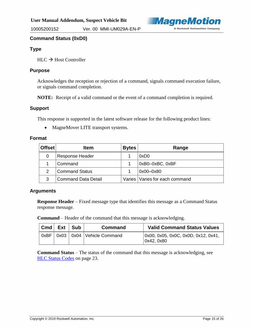
Command Status (0xD0)
Type
HLC Host Controller
Purpose
Acknowledges the reception or rejection of a command, signals command execution failure,
or signals command completion.
NOTE: Receipt of a valid command or the event of a command completion is required.
Support
This response is supported in the latest software release for the following product lines:
MagneMover LITE transport systems.
Format
Offset Item Bytes Range
0 Response Header 1 0xD0
1 Command 1 0xB0–0xBC, 0xBF
2 Command Status 1 0x00–0x80
3 Command Data Detail Varies Varies for each command
Arguments
Response Header – Fixed message type that identifies this message as a Command Status
response message.
Command – Header of the command that this message is acknowledging.
Cmd Ext Sub Command Valid Command Status Values
0xBF 0x03 0x04 Vehicle Command 0x00, 0x05, 0x0C, 0x0D, 0x12, 0x41, 0x42, 0x80
Command Status – The status of the command that this message is acknowledging, see
HLC Status Codes on page 23.

User Manual Addendum, Suspect Vehicle Bit
10005200152 Ver. 00 MMI-UM029A-EN-P
Copyright © 2019 Rockwell Automation, Inc. Page 16 of 26
Command Data Detail – Variable amount of data that provides the details of the command
that is specified in the Command field.
Cmd Ext Sub Command Description Command Data
0xBF 0x03 0x04 Vehicle Command Extension Type (1 byte)
Extension Subtype (1 byte)
Vehicle ID (2 bytes)
Subcommand (1 byte)
See Also
Vehicle Command (0xBF 03 04) on page 12
User Manual Addendum, Suspect Vehicle Bit
10005200152 Ver. 00 MMI-UM029A-EN-P
Copyright © 2019 Rockwell Automation, Inc. Page 17 of 26
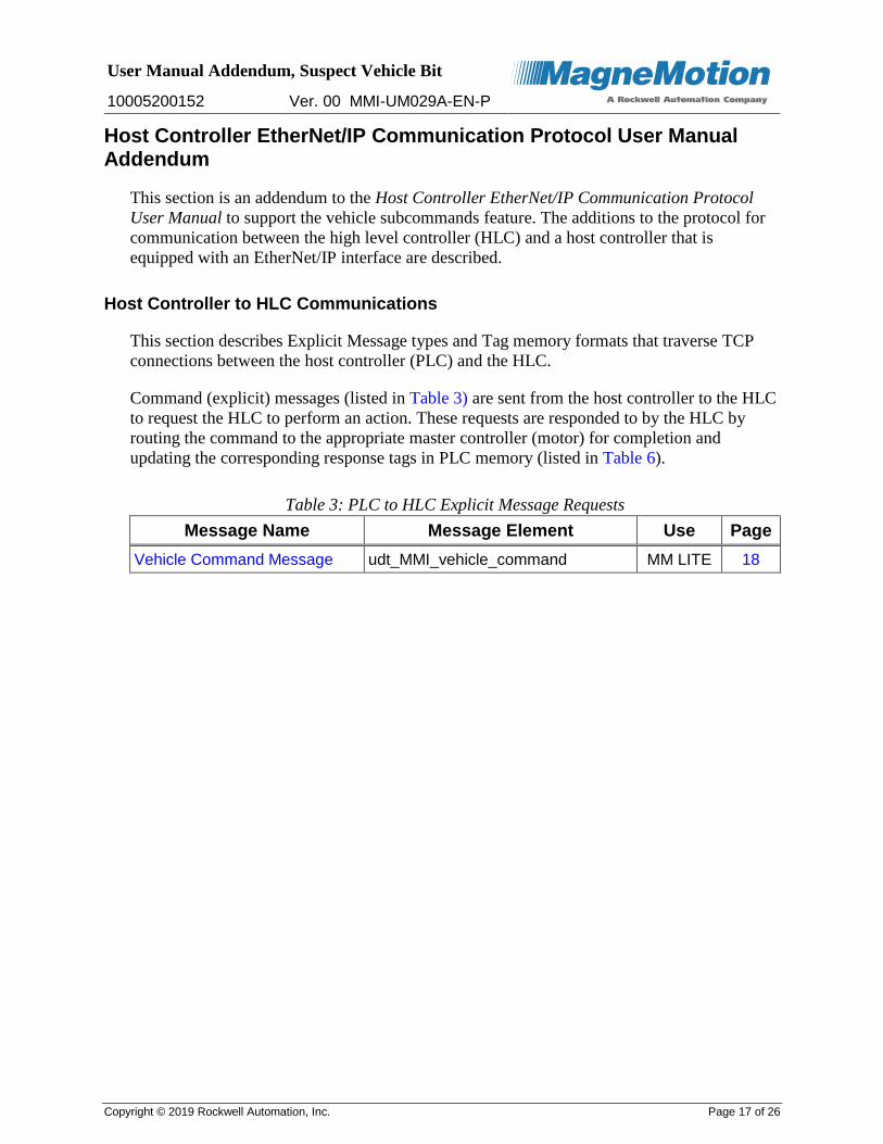
Host Controller EtherNet/IP Communication Protocol User Manual Addendum
This section is an addendum to the Host Controller EtherNet/IP Communication Protocol
User Manual to support the vehicle subcommands feature. The additions to the protocol for
communication between the high level controller (HLC) and a host controller that is
equipped with an EtherNet/IP interface are described.
Host Controller to HLC Communications
This section describes Explicit Message types and Tag memory formats that traverse TCP
connections between the host controller (PLC) and the HLC.
Command (explicit) messages (listed in Table 3) are sent from the host controller to the HLC
to request the HLC to perform an action. These requests are responded to by the HLC by
routing the command to the appropriate master controller (motor) for completion and
updating the corresponding response tags in PLC memory (listed in Table 6).
Table 3: PLC to HLC Explicit Message Requests
Message Name Message Element Use Page
Vehicle Command Message udt_MMI_vehicle_command MM LITE 18

User Manual Addendum, Suspect Vehicle Bit
10005200152 Ver. 00 MMI-UM029A-EN-P
Copyright © 2019 Rockwell Automation, Inc. Page 18 of 26
Vehicle Command Message
Type
Host Controller HLC
Purpose
Contains one or more entries of type udt_MMI_vehicle_command used to specify vehicle
subcommands.
Each command is monitored via its corresponding udt_MMI_vehicle_command_status entry
in the MMI_vehicle_command_status tag.
Support
This command is supported in the latest software release for the following product lines:
MagneMover LITE transport systems.
Message Element Data Type
The UDT that is described in Table 4 shows each field that is used to create
udt_MMI_vehicle_command and its data type, style, and range. The table also shows the size
of the UDT in bytes. Each field is described in more detail following the table.
Table 4: UDT Configuration for udt_MMI_vehicle_command
Field Name Data Type Style Range
vehicle_id INT Decimal 1–65535
subcommand SINT Hex Values are:
0x00 – Clear Vehicle Suspect Bit
active_flag SINT Hex 0 – HLC skips this entry
1 – HLC processes this entry
command_count DINT Hex 0x0–0xFFFFFFFF
Data Type Size 8 bytes
UDT Field Descriptions
vehicle_id – The ID of the vehicle targeted by this command. The ID must be a nonzero
integer that references a vehicle that exists in the transport system.
Subcommand – Fixed value that identifies the vehicle subcommand to execute.
Value Subcommand
0x00 Clear vehicle suspect bit – Commands the master controller (motor) responsible for the specified vehicle to clear the suspect bit in the vehicle record for the vehicle.

User Manual Addendum, Suspect Vehicle Bit
10005200152 Ver. 00 MMI-UM029A-EN-P
Copyright © 2019 Rockwell Automation, Inc. Page 19 of 26
active_flag – This flag is used in configurations where a static table of
udt_MMI_vehicle_command entries is used and the same table is sent every time. The HLC
only processes those entries with the active_flag set.
Value Description
0x00 The HLC skips the entry for this vehicle.
0x01 The HLC processes the entry for this vehicle.
command_count – Host controller derived unique counter, which is used to confirm that the
HLC has received the command and to determine command status. This counter provides a
convenient handshake mechanism to determine command status by matching the counter
with the fields in the MMI_vehicle_command_status array.
Use of a scratch DINT tag as a counter is suggested. The scratch DINT tag can be
incremented and copied to the command_count field each time a new vehicle subcommand is
issued so the new command can be tracked against the various count fields that are described
in MMI_vehicle_command_status.
Message Configuration
The Source Element vehicle_command shown in Table 5 is an array of data type
udt_MMI_vehicle_command. It can be one tag with the Number of Elements set to 1, or it
can an array with the Number of Elements set to the maximum of 256. When the Source
Element is configured to use an array, the message can send multiple
udt_MMI_vehicle_command s to the HLC with one message. The Destination Element is
defined as the name of the tag (MMI_vehicle_command).
Table 5: Message Configuration for MMI_vehicle_command
Message Type CIP Data Table Write
Source Element vehicle_command
Tag Data Type udt_MMI_vehicle_command
Number of Elements Min: 1, Max: 256
Destination Element MMI_vehicle_command
Response
After receiving the command, the HLC verifies the command parameters and updates
MMI_vehicle_command_status as appropriate. If the command is accepted, the HLC routes
the command to the master controller (motor) responsible for the vehicle. Once the command
completes, the HLC updates MMI_vehicle_command_status to indicate completion.
See Also
MMI_vehicle_command_status on page 21

User Manual Addendum, Suspect Vehicle Bit
10005200152 Ver. 00 MMI-UM029A-EN-P
Copyright © 2019 Rockwell Automation, Inc. Page 20 of 26
HLC to Host Controller Communications
This section describes the Status and Response Memory Tags that the HLC updates to
interoperate with the PLC.
The HLC updates the Status Tags (listed in Table 6) on state change. Status Tags are
informational for the PLC for disseminating status about the vehicle command functions.
Table 6: HLC to PLC Status Memory Tags
Message Name Message Element Use Page
MMI_vehicle_command_status udt_MMI_vehicle_command_status MM LITE 21

User Manual Addendum, Suspect Vehicle Bit
10005200152 Ver. 00 MMI-UM029A-EN-P
Copyright © 2019 Rockwell Automation, Inc. Page 21 of 26
MMI_vehicle_command_status
Type
HLC Host Controller
Purpose
Reports the status of vehicle subcommands in the transport system. This tag is a one-
dimension array of type udt_MMI_vehicle_command_status indexed by vehicle ID. This
array must be sized the same as the MMI_vehicle_status array. The current minimum size is
257 entries. The MMI_vehicle_command_status array is updated only in response to an
MMI_vehicle_command message sent from the PLC to the HLC.
This tag array is used to handshake vehicle subcommands so the PLC logic can know that the
HLC received a command. The tag can then be either accepted it for processing, or rejected it
with an appropriate error code. The tag array can be consulted to determine if a command
completed and whether it completed successfully or an error occurred.
Support
This command is supported in the latest software release for the following product lines:
MagneMover LITE transport systems.
Tag Format
Tag Name MMI_vehicle_command_status
Type udt_MMI_vehicle_command_status
Array Yes
Array Dimension Limits Minimum array size: 257 Maximum array size: 1281
Array index corresponds to HLC vehicle ID. Since vehicle ID 0 is invalid, array element 0 is not written to.
Message Element Data Type
The UDT that is described in Table 7 shows each field that is used to create
udt_MMI_vehicle_command_status and its data type, style, and range. The table also shows
the size of the UDT in bytes. Each field is described in more detail following the table.
A tag of name MMI_vehicle_command_status must be created as a one-dimensional array of
the UDT with the size the maximum number of vehicles plus 1. If the transport system has a
known maximum number of vehicles that does not exceed 256, the array can be dimensioned
to the minimum size to save on tag memory space.
User Manual Addendum, Suspect Vehicle Bit
10005200152 Ver. 00 MMI-UM029A-EN-P
Copyright © 2019 Rockwell Automation, Inc. Page 22 of 26
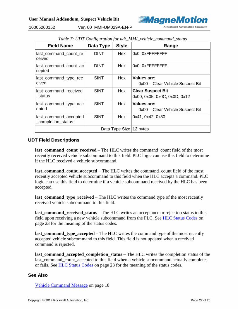
Table 7: UDT Configuration for udt_MMI_vehicle_command_status
Field Name Data Type Style Range
last_command_count_received
DINT Hex 0x0–0xFFFFFFFF
last_command_count_accepted
DINT Hex 0x0–0xFFFFFFFF
last_command_type_received
SINT Hex Values are:
0x00 – Clear Vehicle Suspect Bit
last_command_received_status
SINT Hex Clear Suspect Bit
0x00, 0x05, 0x0C, 0x0D, 0x12
last_command_type_accepted
SINT Hex Values are:
0x00 – Clear Vehicle Suspect Bit
last_command_accepted_completion_status
SINT Hex 0x41, 0x42, 0x80
Data Type Size 12 bytes
UDT Field Descriptions
last_command_count_received – The HLC writes the command_count field of the most
recently received vehicle subcommand to this field. PLC logic can use this field to determine
if the HLC received a vehicle subcommand.
last_command_count_accepted – The HLC writes the command_count field of the most
recently accepted vehicle subcommand to this field when the HLC accepts a command. PLC
logic can use this field to determine if a vehicle subcommand received by the HLC has been
accepted.
last_command_type_received – The HLC writes the command type of the most recently
received vehicle subcommand to this field.
last_command_received_status – The HLC writes an acceptance or rejection status to this
field upon receiving a new vehicle subcommand from the PLC. See HLC Status Codes on
page 23 for the meaning of the status codes.
last_command_type_accepted – The HLC writes the command type of the most recently
accepted vehicle subcommand to this field. This field is not updated when a received
command is rejected.
last_command_accepted_completion_status – The HLC writes the completion status of the
last_command_count_accepted to this field when a vehicle subcommand actually completes
or fails. See HLC Status Codes on page 23 for the meaning of the status codes.
See Also
Vehicle Command Message on page 18

User Manual Addendum, Suspect Vehicle Bit
10005200152 Ver. 00 MMI-UM029A-EN-P
Copyright © 2019 Rockwell Automation, Inc. Page 23 of 26
HLC Status Codes
Table 8 lists the status codes that the HLC returns when it accepts, rejects, or completes
vehicle subcommands.
Table 8: HLC Status Codes
Status Value
Status Description
0x00 Command Accepted
0x05 Command Rejected – E-stop signal active
0x0C Command Rejected – Initialization has not completed
0x0D Command Rejected – Reset active
0x12 Command Rejected – Unrecognized command
0x41 Command Failed – Unable to complete
0x42 Command Failed – Timed out
0x80 Command Completed Successfully

User Manual Addendum, Suspect Vehicle Bit
10005200152 Ver. 00 MMI-UM029A-EN-P
Copyright © 2019 Rockwell Automation, Inc. Page 24 of 26
More Information
MagneMotion website: www.magnemotion.com
Questions and Comments: www.magnemotion.com/about-magnemotion/contact.cfm
Revision History
Ver. Change Description
A Initial release

User Manual Addendum, Suspect Vehicle Bit
10005200152 Ver. 00 MMI-UM029A-EN-P
Copyright © 2019 Rockwell Automation, Inc. Page 25 of 26
Rockwell Automation Support
Use the following resources to access support information.
Technical Support Center Knowledgebase Articles, How-to Videos, FAQs, Chat, User Forums, and Product Notification Updates.
https://rockwellautomation.custhelp.com/
Local Technical Support Phone Numbers
Locate the phone number for your country.
http://www.rockwellautomation.com/global/support/get-support-now.page
Direct Dial Codes Find the Direct Dial Code for your product. Use the code to route your call directly to a technical support engineer.
http://www.rockwellautomation.com/global/support/direct-dial.page
Literature Library Installation Instructions, Manuals, Brochures, and Technical Data.
http://www.rockwellautomation.com/global/literature-library/overview.page
Product Compatibility and Download Center (PCDC)
Get help determining how products interact, check features and capabilities, and find associated firmware.
http://www.rockwellautomation.com/global/support/pcdc.page
Documentation Feedback Your comments will help us serve your documentation needs better. If you have any suggestions on how to improve this document, complete the How Are We Doing? form at http://literature.rockwellautomation.com/idc/groups/literature/documents/du/ra-du002_-en-e.pdf.
Rockwell Automation maintains current product environmental information on its website at http://www.rockwellautomation.com/rockwellautomation/about-us/sustainability-ethics/product-environmental-compliance.page.
Product certificates are located in the Rockwell Automation Literature Library: http://www.rockwellautomation.com/global/literature-library/overview.page
Allen-Bradley, Compact I/O, CompactLogix, ControlLogix, DH+, DriveLogix, FactoryTalk, FLEX, Logix5000, PanelBuilder, PanelView, PLC-2, PLC-3, PLC-5, POINT I/O, PowerFlex, Rockwell Automation, Rockwell Software, RSLinx, RSLogix, RSNetWorx, RSView, SLC, SoftLogix, Studio 5000, and Studio 5000 Logix Designer are trademarks of Rockwell Automation, Inc.
Trademarks not belonging to Rockwell Automation are property of their respective companies.
Rockwell Otomasyon Ticaret A.Ş., Kar Plaza İş Merkezi E Blok Kat:6 34752 İçerenköy, İstanbul, Tel: +90 (216) 5698400
www.rockwellautomation.com

User Manual Addendum, Suspect Vehicle Bit
10005200152 Ver. 00 MMI-UM029A-EN-P
Copyright © 2019 Rockwell Automation, Inc. Page 26 of 26
Power, Control, and Information Solutions Headquarters
Americas: Rockwell Automation, 1201 South Second Street, Milwaukee, WI 53204-2496 USA, Tel: (1) 414.382.2000, Fax: (1) 414.382.4444 Europe/Middle East/Africa: Rockwell Automation NV, Pegasus Park, De Kleetlaan 12a, 1831 Diegem, Belgium, Tel: (32) 2 663 0600, Fax: (32) 2 663 0640 Asia Pacific: Rockwell Automation, Level 14, Core F, Cyberport 3, 100 Cyberport Road, Hong Kong, Tel: (852) 2887 4788, Fax: (852) 2508 1846