(addendum to the urban storm drainage criteria …
TRANSCRIPT

LARIMER COUNTY STORMWATER DESIGN STANDARDS
(ADDENDUM TO THE URBAN STORM DRAINAGE CRITERIA
MANUALS- VOLUMES 1, 2 AND 3)
Larimer County Engineering Department 200 West Oak Street, Suite 3000 P.O. Box 1190 Fort Collins, CO 80522-1190
ADOPTED: JUNE 20, 2005

LARIMER COUNTY
STORMWATER DESIGN STANDARDS
Larimer County standards for Design of facilities for stormwater shall be those found in the Denver Urban Drainage and Flood Control District Stormwater Design Manual, Volumes I, II, and III, as amended herein. Reference to chapters fund below are references to chapters in the Denver Urban Drainage and Flood Control District Stormwater Design Manual.
References to Tables & Figures found below are references to figures contained in this addendum.
Larimer County Engineering Department 200 West Oak Street, Suite 3000 P.O. Box 1190 Fort Collins, CO 80522-1190
ADOPTED: JUNE 20, 2005 Chair, Larimer County Commissioners

06/2005 Larimer County Stormwater Design Standards i
TABLE OF CONTENTS
TITLE PAGE
PREFACE ....................................................................................................................................................................1
DRAINAGE REPORT SUBMITTAL REQUIREMENTS ........................................................................................3
VOLUME 1 ...................................................................................................................................................................8
Drainage Policy .......................................................................................................................................................8 Drainage Law ........................................................................................................................................................12 Planning..................................................................................................................................................................13 Rainfall....................................................................................................................................................................14 Runoff .....................................................................................................................................................................41 Streets/Inlets/Storm Sewers................................................................................................................................42 Major Drainage ......................................................................................................................................................45
VOLUME 2 .................................................................................................................................................................47
Hydraulic Structures .............................................................................................................................................47 Culverts ..................................................................................................................................................................48 Storage ...................................................................................................................................................................50 Floodproofing.........................................................................................................................................................52 Revegetation..........................................................................................................................................................53
VOLUME 3 .................................................................................................................................................................54
Stormwater Quality Management .......................................................................................................................54 NPDES Permit Regulations.................................................................................................................................54 New Development Planning ................................................................................................................................56 Structural BMP’s ...................................................................................................................................................57 Typical Structural BMP Details ...........................................................................................................................58 Maintenance Recommendations ........................................................................................................................59 Industrial and Commercial Best Management Practices ................................................................................60 Nonstructural Best Management Practices.......................................................................................................61 Construction Best Management Practices ........................................................................................................62

06/2005 Larimer County Stormwater Design Standards 1
PREFACE
Previously, design of facilities to accommodate stormwater for new development in Larimer County was based on the Larimer County Stormwater Management Manual, dated 1979. Since that time, there have been advances in the technological science of stormwater management as well as changes in practices used to address stormwater and stormwater quality. The need for adequate engineering standards to accommodate stormwater runoff has become more apparent with the intense growth of the County population and urban areas in recent years. The revised design standards will provide consistent and accurate engineering design of facilities for stormwater management in all developments within the County. For these reasons, the County is proposing to adopt stormwater design standards based on the Denver Urban Drainage and Flood Control District’s (UDFCD) Urban Storm Drainage Criteria Manual, dated 2001, with appropriate revisions to address local conditions. The use of common design standards for design of stormwater facilities along the Front Range will provide consistency for the engineering design community. The Larimer County Stormwater Design Standards are based on the Denver Urban Storm Drainage Criteria Manuals-Volumes 1, 2 and 3. The County is preparing to adopt an Addendum to the Urban Storm Drainage Criteria Manual, dated February 14, 2005 to address the specific needs of the County. Each section of the Addendum corresponds to a respective section of the Denver Urban Storm Drainage Criteria Manual. Except where otherwise noted, the term “Denver Region” or “District” in the Urban Storm Drainage Criteria Manual can be considered to mean “Larimer County” in the Addendum. The Urban Storm Drainage Criteria Manual along with the associated Addendum will be adopted as a Technical Supplement to the Larimer County Land Use Code, and referred to as Larimer County Stormwater Design Standards. One significant change from the Stormwater Management Manual previously used is that the rainfall frequency – intensity relationships are based on those used by the respective major city in each river watershed. The Cache La Poudre River Watershed uses a slightly higher intensity of rainfall. The 100-year rainfall total is 3.67 inches in 2 hours, based on the rainfall frequencies adopted by the City of Fort Collins. Correspondingly, the Big Thompson and Little Thompson river watersheds use the relationship adopted by the City of Loveland, for which the 100-year rainfall is 3.02 inches in a two hour period. This change is necessary, since the design standards must be consistent with the respective drainage basin master plans. Stormwater master plans prepared by the City of Fort Collins are also used in the County, as is the City of Loveland Drainage Master Plan. Another significant change from the Stormwater Management Manual previously used is the adoption of Volume 3, a more comprehensive guide to Best Management Practices. Volume 3 also provides a detailed approach to handling stormwater quality issues as required by Phase II of National Pollutant Discharge Elimination System (NPDES). The Larimer County Stormwater Design Standards utilizes up to date technology and procedures. Due to the dynamic nature of urban storm drainage, amendments and revision are expected as experience is gained in the use of The Urban Drainage Criteria Manual and Addendum. Amendments and revisions will be posted with the Larimer County Engineering Department link of the Larimer County Web Page, www.larimer.org/engineering and on the UDFCD web site at www.udfcd.org.
Questions concerning the material in the Manual or suggestions for improvements should be directed to:

Larimer County Engineering Department Stormwater Engineer 200 West Oak Street, Suite 3000 P.O. Box 1190 Fort Collins, CO 80522-1190 (970) 498-5700 [email protected]
06-2005 Larimer County Stormwater Design Standards 2

06/2005 Larimer County Stormwater Design Standards 3
DRAINAGE REPORT SUBMITTAL REQUIREMENTS
This section outlines the report requirements and procedures for submittal of drainage plans and reports. The requirements for submittal shall include a preliminary drainage report, a final drainage report and construction plans for drainage improvements. All plans and drawings not in the reports shall be on 24" x 36" paper. All storm drainage plans shall be checked for conformance to the design criteria set forth in this Manual. Written approval of drainage plans must be obtained before any construction begins. Procedures and deadlines for submittal of drainage plans shall be as outlined in the appropriate sections of the Larimer County Land Use Code. Preliminary Drainage Report This report shall be submitted to the Larimer County Planning Department as required by the Larimer County Land Use Code. The purpose of the preliminary drainage report is to present a conceptual plan for handling drainage prior to actual sizing of facilities. This report shall be approved by the Larimer County Engineer prior to submittal of the final drainage report. The preliminary drainage report shall include but not be limited to the following items:
1. The report shall include an analysis of overall drainage considerations which will include a map of the major watershed in which the development is located. This map should be of sufficient detail to identify the various paths of flows of drainage waters from the development and identify any major constriction such as other development along the path of drainage. This analysis shall proceed downstream to a major creek or river; i.e., Cache la Poudre River, Little Thompson River, etc. In addition, this analysis must identify areas off site of the development from which drainage water shall enter the development.
2. The report should identify all nearby irrigation ditches, reservoirs, emergency
spillways, or other irrigation facilities which will affect or be affected by drainage in the area. Also, a statement must be made as to the effect of the development on hazard ratings of any reservoirs in the area (refer to Policy 1.3.2-2).
3. The report must show peak flows for drainages entering and leaving the
development for the minor and major storms. Assumptions for upstream development must take into account planned development upstream and be based on information and discussions with adjacent property owners and the Larimer County Planning Department. These assumptions should be clearly stated and justifications for the assumptions must be presented. Flows shall be computed for the existing and fully developed conditions of the site. Data and procedures utilized in determining peak flows shall be included for verification of the results.
4. Provisions for site drainage shall be displayed on a 24" x 36"
format. These drawings shall contain the preliminary design for the minor and major drainage systems within the development. Drainage plans shall be submitted in two separate phases showing the effects of the minor storm runoff and the major storm runoff and each shall include the following information:
a. Topographic contours (2-ft. contour interval proposed and existing) on USGS
Datum. b. Location and elevations of USGS Bench Marks. All elevations shall be on
USGS Datum.

06/2005 Larimer County Stormwater Design Standards 4
c. Property lines. d. Streets, names, and grades. e. Existing drainage facilities and structures, including existing irrigation ditches,
roadside ditches, drainageways, gutter flow directions, culverts, etc. All pertinent information, such as size, shape, slope, location, etc., that will facilitate review and approval of drainage plans.
f. Overall drainage area boundary and drainage sub-area boundaries. g. Proposed type of curb and gutter (vertical or combination) and gutter flow
directions, including cross pans. h. Proposed piping and open drainageways, including proposed inlets, manholes,
culverts, and other appurtenances. i. Proposed outfall point(s) for runoff from the study area. J. Routing and accumulative flows at various critical points for the minor storm
runoff. k. Routing and accumulative flows at various critical points for the major storm
runoff. l. Minimum lowest floor elevations for protection from major storm runoff.
5. Documentation and data utilized in the preliminary sizing of the drainage facilities are required to be submitted in the report.
6. Soil classification reports, depth and seasonal fluctuations of the underground water
table throughout the development, and details of any proposed subsurface drainage systems or proposed alterations to existing subsurface drainage systems shall be provided.
7. Details of the relationship of proposed drainage facilities to existing or planned
drainage facilities in surrounding properties or developments shall be included in the report. A statement shall be included indicating the relationship of the proposed drainage facilities to the master drainage plan for the affected basin, if such a plan exists. In cases where the point of outfall or peak flow from the property is other than historic, binding agreements from affected property owners permitting such discharge shall be submitted.
8. In cases where all or any part of a development falls within a designated flood
hazard area, the flood hazard area shall be shown on the plan, along, with computed floodwater surface elevations.
9. The preliminary drainage report and plans must be certified that they were prepared
under the direct supervision of a registered professional engineer in the State of Colorado using the following certification:

06/2005 Larimer County Stormwater Design Standards 5
I hereby certify that this report (plan) for the preliminary drainage design of _______________________ was prepared by me (or under my direct supervision) for the owners thereof and meet or exceed the criteria in the Larimer County Stormwater Design Standards.
___________________________
Registered Professional Engineer State of Colorado No. _________
(Seal)
Final Drainage Report This final drainage report shall be submitted for approval along with the final plat and the construction drawings. The report shall be submitted in five copies, When approved, the report will be signed by the County Engineer and shall constitute conceptual approval of the drainage plan. The report shall include the information submitted in the preliminary report, with any additions, modifications, or corrections required, In addition, the final drainage report shall include the following:
1. Street capacity calculations at critical street sections for minor storm runoff and major storm runoff.
2. A profile showing hydraulic grade lines, ground surface grade, and pipe grade for all
storm sewers for the minor and major storms. 3. Backwater profiles for open channels for the minor and major storm runoff with input
data and procedures used for the calculations. 4. Culvert design calculations with all input data and procedures used. 5. Historic inflow, developed inflow and outflow design hydrographs for detention
facilities. 6. Stage-volume curves, outlet rating curves, spillway rating curves, and the method
used to determine the rating curves for storm water storage facilities. 7. An erosion control plan. This plan should indicate methods to be used during and
after construction to control erosion and sediment in the development. (As a supplement to the report, 24" x 36" drawings may be necessary to illustrate the methods and structures to be used.)
8. A statement which describes the safety hazards that may be associated with the
various drainage structures and the provisions that have been included in the design to minimize safety hazards.
9. Certification similar to item 9 for the preliminary report.
06/2005 Larimer County Stormwater Design Standards 6
Construction Plans and Details All storm drainage plans shall be checked for conformance with the minimum design criteria set forth in this Manual prior to approval. Prior to submittal of the final construction drawings, one complete set of prints shall be submitted for review and comment and will be returned if changes are required or recommended. Two complete sets of revised prints shall then be submitted for final approval along with the original review print.
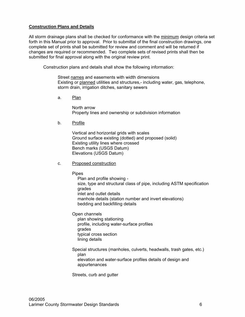
Construction plans and details shall show the following information:
Street names and easements with width dimensions Existing or planned utilities and structures,- including water, gas, telephone, storm drain, irrigation ditches, sanitary sewers
a. Plan
North arrow Property lines and ownership or subdivision information
b. Profile
Vertical and horizontal grids with scales Ground surface existing (dotted) and proposed (solid) Existing utility lines where crossed Bench marks (USGS Datum) Elevations (USGS Datum)
c. Proposed construction Pipes
Plan and profile showing - size, type and structural class of pipe, including ASTM specification grades inlet and outlet details manhole details (station number and invert elevations) bedding and backfilling details
Open channels
plan showing stationing profile, including water-surface profiles grades typical cross section lining details
Special structures (manholes, culverts, headwalls, trash gates, etc.)
plan elevation and water-surface profiles details of design and appurtenances
Streets, curb and gutter

06/2005 Larimer County Stormwater Design Standards 7
The following details should be shown on each and every page of all drawings:
a. Title block (lower right-hand corner) b. North arrow c. Scale 1" - 5' vertical, 1" - 50' horizontal, where possible (Plan and Profile) d. Date and revisions e. Name of professional engineer or firm f. Professional engineer's seal and signature g. Statement:
All work shall be constructed in accordance with Larimer County Standard Specifications as provided by the County Engineer, except as noted.
APPROVED:_________________________________
DATE:_________________________________
All new developments within Larimer County are required to submit for review and approval an overall site certification of the constructed drainage facilities. The overall site certification must specify the proposed and the as-built conditions of the site's drainage facilities. Any variation from the approved plans must be noted and proven to function properly within standards as in the Stormwater Design Criteria. Supporting calculations to justify any variation from the approved plans shall be provided including but not limited to: detention volumes, pipe capacities, and swale capacities. Individual lot or building certification may be required depending on the site design, prior to the release of a certificate of occupancy by the County Building Department. Certification of drainage facilities shall be submitted to the County Engineer at least two weeks prior to release of collateral or the release of a certificate of occupancy.

06/2005 Larimer County Stormwater Design Standards 8
VOLUME 1
Drainage Policy 1.4 Planning
Change Stormwater Runoff can be stored in detention and retention reservoirs. To Stormwater Runoff can be stored in detention reservoirs. Under special
circumstances in the Growth Management Areas, as defined in the Larimer County Land Use Code, storm water runoff can be stored in retention reservoirs with proper approval from the County Engineer in accordance with the Land Use Code.
1.5 Technical Issues
Change …(CUHP), or… To …(CUHP), HEC-1, ModSWMM, UDSWM or….
Change The various governmental agencies within the Denver Region have
adopted and need to maintain their floodplain management programs To The County has adopted and will maintain its floodplain management
program 1.7 Implementation
Delete Entire second paragraph, including Figure DP-1 2.1 Drainage Is A Regional Phenomenon That Does Not Respect The Boundaries Between
Government Jurisdiction Or Between Properties
Add Larimer County has entered into Agreements with the City of Fort Collins and the City of Loveland to cooperate on Regional Drainage Planning for the designated Growth Management Areas. The policy of Larimer County shall be to pursue a jurisdictionally unified drainage effort to assure an integrated plan and to cooperate with other regional and local planning agencies on drainage matters. Larimer County will also encourage, and continue to be involved in development of watershed level policy for the various watersheds within the County.
2.2 A Storm Drainage System Is A Subsystem Of The Total Water Resource System
Change Stormwater system planning and design for any site must be compatible with comprehensive region plans…
To Stormwater system planning and design for any site must be compatible with comprehensive regional and watershed level drainage plans…
3.1 Data Collection
Change …storm runoff and flood data should… To …storm runoff, flood data and water quality should…

06/2005 Larimer County Stormwater Design Standards 9
3.2 Floodplain Data
Delete “the Districts Flood Hazard Area Delineation Studies”
Change …the USGS, and floodplain studies by private consulting engineers. To …the USGS, floodplain studies by private consulting engineers and
locally designated flood plains. 3.2.2 Data Inventory
Change The information collected should be stored in a central District depository…
To The information collected should be stored in a Stormwater Utility file… 3.2.3 Infiltration
Add When working within the City of Fort Collins’ Growth Management Area, the City’s infiltration parameters should be utilized.
3.3.1 Master Plan
Change Such plans already cover most of the developed major drainage ways in the District.
To Such plans already cover most of the developed major drainage ways in the Growth Management Areas.
4.1 Total Urban System
Change …compatible with comprehensive regional plans. To …compatible with comprehensive regional and watershed plans.
Change …most of the watersheds in the Denver Region. To … most of the watersheds in the Growth Management Areas.
Change …until full coverage is achieved. To …until full coverage of urbanized areas is achieved.
4.1.2 Master Plan
Change Each municipality and County in the Denver Region is… To Each municipality in Larimer County is…
Change …and joint City, County and District efforts are encouraged. To …and joint City and County efforts are encouraged
Add Larimer County shall enforce and implement the adopted Master
Drainage Plans in the Growth Management Areas of Fort Collins and Loveland. These Master Drainage Plans and the Growth Management Area boundaries may be amended from time to time in the future.

06/2005 Larimer County Stormwater Design Standards 10
4.3.4 Maintenance and Maintenance Access
Delete The District assists with drainage facility maintenance, provided that the facilities are designed in accordance with the District’s maintenance eligibility guidelines. The June 2001 version of these guidelines are available on the CD version of this manual, and updates to these guidelines should be obtained from the District’s website at www.udfcd.org. Designers are strongly encouraged to adhere to the design criteria listed in the maintenance guidelines.
4.5 Detention and Retention Storage
Change Stormwater Runoff can be stored in detention and retention reservoirs. To Stormwater Runoff can be stored in detention reservoirs. Under special
circumstances in the Growth Management Areas, storm water runoff can be stored in retention reservoirs with proper approval.
4.5.1 Upstream Storage
Add Parking lots may be used to provide infrequent storage for runoff to the extent such storage is practical and provided that the depth of ponding does not preclude safe operation of vehicles.
4.5.3 Downstream Storage
Change The detention and retention of stormwater runoff… To The detention of stormwater runoff… Under special circumstances in the
Growth Management Areas, storm water runoff can be stored in retention reservoirs with proper approval.
5.1.1 Design Criteria
Add Administrative appeals of the design criteria in the Larimer County Stormwater Design Standards may be granted by the Larimer County Engineer, in accordance with the Land Use Code, by acceptance of the Final Drainage Report in which the administrative appeal is well documented.
5.4 Streets
Change …as summarized in Table DP-1. To …as summarized in the Streets/Inlets/Storm Sewer chapter.
Delete Table DP-1 in its entirety
Change …as summarized in Table DP-2. To …as summarized in the Streets/Inlets/Storm Sewer chapter.
Delete Table DP-2 in its entirety
Change …presented in Table DP-3. To …presented in the Streets/Inlets/Storm Sewer chapter .
Delete Table DP-3 in its entirety

06/2005 Larimer County Stormwater Design Standards 11
6.3 National Flood Insurance Program
Change Flood Insurance should be an integral part of a strategy to manage flood losses.
To Flood Insurance will be an integral part of a strategy to manage flood losses in Larimer County.
Change The cities and counties…. To The cities….

06/2005 Larimer County Stormwater Design Standards 12
VOLUME 1
Drainage Law The Drainage Law Chapter is deleted in its entirety. No Drainage Law chapter will be provided.

06/2005 Larimer County Stormwater Design Standards 13
VOLUME 1
Planning The Planning Chapter is adopted in its entirety.
06/2005 Larimer County Stormwater Design Standards 14
VOLUME 1
Rainfall Delete Entire Chapter Add The following chapter on rainfall precipitation-frequency relationships in
its entirety.

06/2005 Larimer County Stormwater Design Standards 15
PRECIPITATION-FREQUENCY RELATIONSHIPS
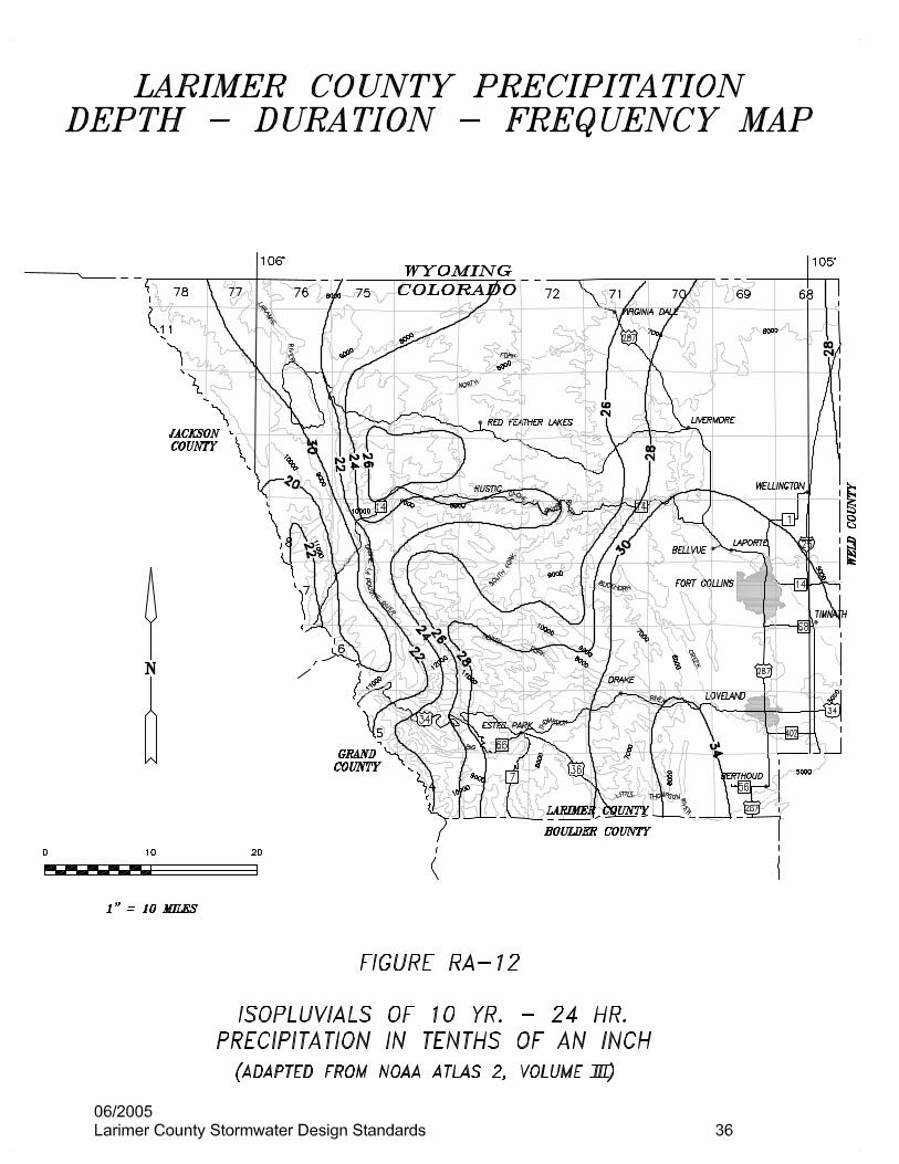
Precipitation-frequency relationships are prerequisites for valid drainage planning and design. For purposes of drainage planning and design in Larimer County. The County was divided into three major hydrologic areas (Fig. RA-1), as follows:
Area I. The area contained within the watershed boundaries of the master planned basins surrounding the City of Fort Collins. This area may be approximately described as the area extending from the east County line west to the foothills and from the watershed divide between the Cache la Poudre and Big Thompson rivers at approximately County Road 30 on the south north to the watershed boundaries of Dry Creek and Boxelder Creek basins.
Area II. The area near Loveland from the east county line to the first “hogback” on
the west and from the south county line to the watershed divide between the Big Thompson and Cache la Poudre Rivers on the north.
Area III. The remainder of the county not in Area I or Area II. The precipitation-frequency data for each area are different in order to closely match the local precipitation regimes. Two sources of information are used in three geographic areas. The first source of information is the National Oceanic and Atmospheric Administration Precipitation Frequency Atlas of the Western United States, 2, Volume III-Colorado. These relationships are those used for hydrological determinations in Areas II and III. The second source of information is the City of Fort Collins rainfall criterion which was developed by a task force following major flooding in the Fort Collins area in 1997. The City of Fort Collins rainfall information is used for Area I. The data and procedures used in this section will be revised periodically to keep information current. The user is expected to use the most-up-date revision of these Standards. 1.1 NOAA Atlas Procedures developed by the National Oceanic and Atmospheric Administration (NOAA) and published in Precipitation Frequency Atlas of the Western United States, 2, Volume III-Colorado (Miller et al., 1973) have been adapted for use in Larimer County. (Hereinafter this publication will be referred to as NOAA Atlas.) These procedures and data were further verified with 34 years of hourly precipitation data for Fort Collins, and precipitation-frequency curves were developed for the plains area of Larimer County. Due to the extreme climatological variations in the mountainous regions of the County, methods were adapted from the NOAA Atlas to determine precipitation-frequency relationships for these mountainous areas. The most up-to-date procedures for determining precipitation-frequency relationships, then, are those contained on the NOAA Atlas. This Atlas presents charts of precipitation of 6- and 24- hour durations for return periods between 2 and 100 years, and supersedes U.S. Weather Bureau Technical Paper No. 40 developed in 1961. The main emphasis of the Atlas is to more accurately depict the variation in the precipitation-frequency regimes for mountainous regions. Also, it takes into account regional relationships between stations, and presents a better regional pattern of precipitation than an analysis of just the stations in Larimer County would produce.
06/2005 Larimer County Stormwater Design Standards 16
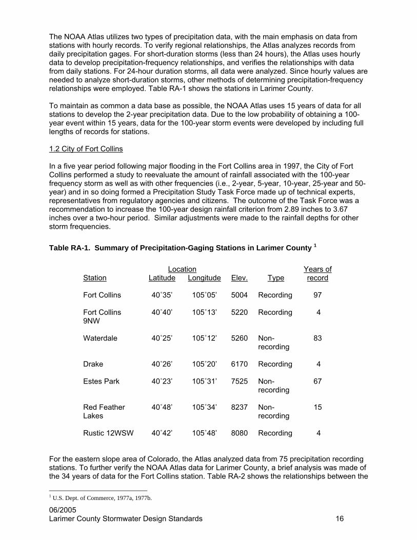
The NOAA Atlas utilizes two types of precipitation data, with the main emphasis on data from stations with hourly records. To verify regional relationships, the Atlas analyzes records from daily precipitation gages. For short-duration storms (less than 24 hours), the Atlas uses hourly data to develop precipitation-frequency relationships, and verifies the relationships with data from daily stations. For 24-hour duration storms, all data were analyzed. Since hourly values are needed to analyze short-duration storms, other methods of determining precipitation-frequency relationships were employed. Table RA-1 shows the stations in Larimer County. To maintain as common a data base as possible, the NOAA Atlas uses 15 years of data for all stations to develop the 2-year precipitation data. Due to the low probability of obtaining a 100-year event within 15 years, data for the 100-year storm events were developed by including full lengths of records for stations. 1.2 City of Fort Collins In a five year period following major flooding in the Fort Collins area in 1997, the City of Fort Collins performed a study to reevaluate the amount of rainfall associated with the 100-year frequency storm as well as with other frequencies (i.e., 2-year, 5-year, 10-year, 25-year and 50-year) and in so doing formed a Precipitation Study Task Force made up of technical experts, representatives from regulatory agencies and citizens. The outcome of the Task Force was a recommendation to increase the 100-year design rainfall criterion from 2.89 inches to 3.67 inches over a two-hour period. Similar adjustments were made to the rainfall depths for other storm frequencies.
Table RA-1. Summary of Precipitation-Gaging Stations in Larimer County 1
Location Years of Station Latitude Longitude Elev. Type record Fort Collins 40˚35’ 105˚05’ 5004 Recording 97 Fort Collins 9NW
40˚40’ 105˚13’ 5220 Recording 4
Waterdale 40˚25’ 105˚12’ 5260 Non-
recording 83
Drake 40˚26’ 105˚20’ 6170 Recording 4 Estes Park 40˚23’ 105˚31’ 7525 Non-
recording 67
Red Feather Lakes
40˚48’ 105˚34’ 8237 Non-recording
15
Rustic 12WSW 40˚42’ 105˚48’ 8080 Recording 4
For the eastern slope area of Colorado, the Atlas analyzed data from 75 precipitation recording stations. To further verify the NOAA Atlas data for Larimer County, a brief analysis was made of the 34 years of data for the Fort Collins station. Table RA-2 shows the relationships between the
1 U.S. Dept. of Commerce, 1977a, 1977b.

06/2005 Larimer County Stormwater Design Standards 17
6-hour storms as developed from the NOAA Atlas and those developed from only the Fort Collins station data. This analysis would indicate that the NOAA Atlas data does accurately predict the precipitation-frequency relationships for the Fort Collins area. A similar analysis of 86 years of Denver data (Urbonas, 1978) produced approximately the same results as the NOAA Atlas data.
Table RA-2. Comparison of Historical Data for Fort Collins Stations with the NOAA Atlas
Fort Collins station data 34-year Analysis
1940-1973 6-hour precipitation NOAA Atlas 6 hour precipitation Return frequency (inches) (inches)
2-year 1.49 1.43 5-year 1.83 1.96
10-year 2.18 2.28 50-year 3.04 3.08
100-year 3.41 3.45 Precipitation-Frequency relationships for Larimer County were derived by using two methods to develop the data. Using data from the NOAA Atlas, the variations of precipitation-frequency relationships along the plains area of Larimer County were analyzed. Then, due to the extreme changes in precipitation patterns within the mountainous regions of the County, the procedures of the NOAA Atlas and the data for Larimer County were analyzed to develop site-specific precipitation-frequency data for the mountainous regions. 1.3.1 Precipitation frequency data for Areas I and II The rainfall design standards for Area I are based on the City of Fort Collins hydrologic investigation and rainfall design criteria adopted by the City on March 16, 1999. Precipitation data for Area II have been computed from the NOAA Atlas. These standards should be used with the procedures presented in Section 4 of this Manual to determine the design hydrology of the watersheds in Areas I and II. The computed data are as follows: Area I Area II Intensity Frequency Duration Curve (for use with Rational Method) Figure RA-2 Figure RA-3 Design storms: 2 hours – 5 min Table RA-3 Table RA-4 3 hours – 10 min Table RA-5 Precipitation data: 6 hours, and 24 hours Table RA-6

06/2005 Larimer County Stormwater Design Standards 18
Figure RA-2. Rainfall Intensity – Duration – Frequency Curve for Area I

Table RA-3: City of Fort Collins Design Storm Incremental Precipitation for Area I 100 Year 50 Year 25 Year 10 Year 5 Year 2 Year
Time (min)
Intensity (in/hr)
Increments (in)
Intensity (in/hr)
Increments(in)
Intensity (in/hr)
Increments(in)
Intensity (in/hr)
Increments(in)
Intensity (in/hr)
Increments(in)
Intensity (in/hr)
Increments (in)
5 1.00 0.08 0.79 0.07 0.63 0.05 0.49 0.04 0.40 0.03 0.29 0.0210 1.14 0.09 0.90 0.07 0.72 0.06 0.56 0.05 0.45 0.04 0.33 0.0315 1.33 0.11 1.05 0.09 0.84 0.07 0.65 0.05 0.53 0.04 0.38 0.0320 2.23 0.19 1.77 0.15 1.41 0.12 1.09 0.09 0.89 0.07 0.64 0.0525 2.84 0.24 2.25 0.19 1.80 0.15 1.39 0.12 1.13 0.09 0.81 0.0730 5.49 0.46 4.36 0.36 3.48 0.29 2.69 0.22 2.19 0.18 1.57 0.1335 9.95 0.83 7.90 0.66 6.30 0.52 4.87 0.40 3.97 0.33 2.85 0.2440 4.12 0.34 3.27 0.27 2.61 0.22 2.02 0.17 1.64 0.14 1.18 0.1045 2.48 0.21 1.97 0.16 1.57 0.13 1.21 0.10 0.99 0.08 0.71 0.0650 1.46 0.12 1.16 0.10 0.92 0.08 0.71 0.06 0.58 0.05 0.42 0.0355 1.22 0.10 0.97 0.08 0.77 0.06 0.60 0.05 0.49 0.04 0.35 0.0360 1.06 0.09 0.84 0.07 0.67 0.06 0.52 0.04 0.42 0.03 0.30 0.0265 1.00 0.08 0.79 0.07 0.62 0.05 0.39 0.03 0.28 0.02 0.20 0.0270 0.95 0.08 0.75 0.06 0.59 0.05 0.37 0.03 0.27 0.02 0.19 0.0275 0.91 0.08 0.72 0.06 0.56 0.05 0.35 0.03 0.25 0.02 0.18 0.0180 0.87 0.07 0.69 0.06 0.54 0.04 0.34 0.03 0.24 0.02 0.17 0.0185 0.84 0.07 0.66 0.05 0.52 0.04 0.32 0.03 0.23 0.02 0.17 0.0190 0.81 0.07 0.64 0.05 0.50 0.04 0.31 0.03 0.22 0.02 0.16 0.0195 0.78 0.06 0.62 0.05 0.48 0.04 0.30 0.02 0.21 0.02 0.15 0.01100 0.75 0.06 0.60 0.05 0.47 0.04 0.29 0.02 0.20 0.02 0.15 0.01105 0.73 0.06 0.58 0.05 0.45 0.04 0.28 0.02 0.19 0.02 0.14 0.01110 0.71 0.06 0.56 0.05 0.44 0.04 0.27 0.02 0.19 0.02 0.14 0.01115 0.69 0.06 0.54 0.04 0.42 0.03 0.26 0.02 0.18 0.01 0.13 0.01120 0.67 0.06 0.53 0.04 0.41 0.03 0.25 0.02 0.18 0.01 0.13 0.01
06/2005 Larimer County Stormwater Design Standards 19

06/2005 Larimer County Stormwater Design Standards 20
Figure RA-3: Rainfall Intensity - Duration Curve for Area II Loveland Area

06/2005 Larimer County Stormwater Design Standards 21
Table RA-4: Area II - Loveland – 2-hour Design Storms
Total Precipitation
(inches)
2 hour - 5 minute Storms
Time 2 year 5 year 10 year 25 year 50 year 100 year 5 0.29 0.41 0.49 0.59 0.68 0.77
10 0.45 0.64 0.76 0.92 1.06 1.20 15 0.57 0.81 0.96 1.16 1.34 1.52 20 0.66 0.94 1.12 1.36 1.54 1.78 25 0.73 1.04 1.24 1.50 1.71 1.98 30 0.79 1.12 1.33 1.61 1.86 2.10 35 0.83 1.19 1.41 1.70 2.00 2.30 40 0.87 1.25 1.48 1.78 2.10 2.39 45 0.91 1.30 1.54 1.85 2.18 2.47 50 0.94 1.34 1.60 1.91 2.25 2.54 55 0.97 1.38 1.65 1.97 2.31 2.60 60 1.00 1.41 1.69 2.03 2.36 2.66 65 1.03 1.44 1.73 2.08 2.40 2.71 70 1.06 1.47 1.76 2.12 2.44 2.75 75 1.08 1.50 1.79 2.16 2.48 2.79 80 1.10 1.52 1.81 2.18 2.52 2.82 85 1.11 1.54 1.83 2.22 2.55 2.85 90 1.12 1.55 1.85 2.25 2.58 2.88 95 1.13 1.56 1.87 2.27 2.60 2.91
100 1.14 1.57 1.89 2.29 2.61 2.93 105 1.15 1.58 1.91 2.30 2.62 2.95 110 1.16 1.59 1.92 2.31 2.63 2.97 115 1.17 1.60 1.93 2.32 2.64 2.99 120 1.18 1.61 1.94 2.33 2.65 3.01

06/2005 Larimer County Stormwater Design Standards 22
Table RA-5: Area II - Loveland – 3-hour Design Storms Total Precipitation
(inches)
3 hour - 10 minute Storms
Time 2 year 5 year 10 year 25 year 50 year 100 year 10 0.45 0.64 0.76 0.92 1.06 1.20 20 0.66 0.94 1.12 1.36 1.54 1.78 30 0.79 1.12 1.33 1.61 1.86 2.10 40 0.87 1.25 1.48 1.78 2.10 2.39 50 0.94 1.34 1.60 1.91 2.25 2.54 60 1.00 1.41 1.69 2.03 2.36 2.66 70 1.06 1.47 1.76 2.12 2.44 2.75 80 1.10 1.52 1.81 2.19 2.52 2.82 90 1.13 1.56 1.85 2.25 2.57 2.88
100 1.17 1.59 1.89 2.30 2.62 2.94 110 1.20 1.62 1.93 2.34 2.66 3.00 120 1.23 1.65 1.97 2.38 2.70 3.05 130 1.25 1.67 2.01 2.42 2.74 3.10 140 1.27 1.69 2.04 2.45 2.77 3.15 150 1.29 1.71 2.07 2.48 2.80 3.19 160 1.30 1.73 2.09 2.51 2.83 3.23 170 1.31 1.75 2.11 2.53 2.85 3.25 180 1.32 1.76 2.12 2.55 2.87 3.27

06/2005 Larimer County Stormwater Design Standards 23
Table RA-6: Area II - Loveland 6 hour & 24 hour Precipitation Data
Return 6-hour 24-hour frequency (inches) (inches)
2-year 1.53 2.12 5-year 2.00 2.80
10-year 2.42 3.25 25-year 2.90 4.00 50-year 3.22 4.52
100-year 3.68 5.10

06/2005 Larimer County Stormwater Design Standards 24
1.4 Precipitation frequency data for Area III The precipitation data for Area III can be developed utilizing the procedures presented in the NOAA Atlas. These procedures are outlined as follows:
Step 1. Determine the location (range, township, and section) and average elevation of the watershed being considered.
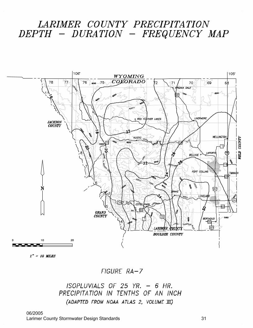
Step 2. Determine the 6-hour and 24-hour precipitation for the 2-, 5-, 10, 25, 50, and
100-year storms from Figures RA-4 through Ra-15.
Step 3. Calculate the 2-year and 100-year and 1-hour precipitation from the following equations:
Y₂ = 0.218 + 0.709 [(X₁)(X₁/X₂)] (Equation RA-1) Y₁₀₀ = 1.897 + 0.439 [(X₃)(X₃/X₄)] – 0.008Z (Equation RA-2) Where: Y₂ = 2-year 1 hour estimated precipitation Y₁₀₀ = 100-year 1-hour estimated precipitation X₁ = 2-year 6-hour value (from Figure RA-4) X₂ = 2-year 24-hour value (from Figure RA-10) X₃ = 100-year 6-hour value (from Figure RA-9) X₄ = 100-year 24-hour value (from RA-15) Z = point elevation in hundreds of feet.
Step 4. Calculate the 1-hour precipitation for return periods between 2-year and 100-year from the following equations:
Y₅ = 0.175Y₂ + 0.249Y₁₀₀ (Equation RA-3) Y₁₀ = 0.588Y₂ + 0.412Y₁₀₀ (Equation RA-4) Y₂₅ = 0.379Y₂ + 0.621Y₁₀₀ (Equation RA-5) Y₅₀ = 0.185Y₂ + 0.815Y₁₀₀ (Equation RA-6) Where: Y₂ = 2-year 1-hour value determined from Equation RA-1 Y₅ = 5-year 1-hour value Y₁₀ = 10-year 1-hour value Y₂₅ = 25-year 1-hour value Y₅₀ = 50-year 1-hour value Y₁₀₀ = 100-year 1-hour value determined from Equation RA-2

06/2005 Larimer County Stormwater Design Standards 25
Step 5. Calculate the 2-hour and 3-hour precipitation for all return frequencies from the following equations:
2-hour = 0.342 (6 hour) + 0.658 (1 hour) (Equation RA-7) 3-hour = 0.597 (6 hour) + 0.403 (1 hour) (Equation RA-8)
Step 6. Utilize the following ratios for determining the precipitation for less than 1 hour.
Duration (minutes):
5 10 15 30
Ratio to 1 hour:
0.29 0.45 0.57 0.79
Step 7. Utilize the data to plot intensity duration-frequency curves. To develop a design
storm, refer to Section 4.

06/2005 Larimer County Stormwater Design Standards 26
Example of obtaining rainfall-frequency data in Area III.
Step 1. An intensity-duration for the 10-year storm is needed for Red Feather Lakes, located in Section 28, Township 10 North, Range 73 East, at elevation 8,300 feet.
Steps 2 and 3. From Figures RA-4 through RA-15 the following data are obtained: Duration: 6-hour 24-hour 2-year = 1.20 1.80 10-year = 1.86 2.60 100-year = 2.80 3.80 Step 4. Utilizing equations RA-1, RA-2, and RA-4 to determine the 1-hour values: Y₂ = 0.218 + 0.709 [(1.20)(1.20/1.80)] Y₂ = 0.79 inches Y₁₀₀ = 1.897 + 0.439 [(2.80)(2.80/3.80)]-(.008)(83) Y₁₀₀ = 2.14 inches Y₁₀ = 0.588 (0.79) + 0.412 (2.14) Y₁₀ = 1.35 inches Step 5. Calculate the 2-hour and 3-hour 10-year precipitation using equations RA-7 and RA-8: (2-hour) = 0.342 (1.86) + 0.658 (1.35) = 1.52 inches or 0.76 inch/hour (3-hour) = 0.597 (1.86) + 0.403 (1.35) = 1.65 inches or 0.55 inch/hour Step 6. Calculate the 5-, 10-, 15-, and 30-minute 10-year rainfalls using ratios in Step 6. (5-minutes) = 0.29(1.35) = 0.39 inches or 4.68 inches/hour (10-minutes) = 0.45(1.35) = 0.61 inches or 3.66 inches/hour (15-minutes) = 0.57(1.35) = 0.77 inches or 3.08 inches/hour (30-minutes) = 0.79(1.35) = 1.07 inches or 2.15 inches/hour Step 7. Utilizing the calculated data, the rainfall frequency-intensity curve is drawn as shown in
Figure RA-16.


06/2005 Larimer County Stormwater Design Standards 41
VOLUME 1
Runoff The Runoff Chapter is adopted in its entirety.
06/2005 Larimer County Stormwater Design Standards 42
VOLUME 1
Streets/Inlets/Storm Sewers 2.2 Design Considerations
Change These standards were given in the POLICY chapter and are repeated in Table ST-2 for convenience.
To These standards are provided in Table ST-2A. Delete Table ST-2
Change These standards were given in the POLICY chapter and are repeated in Table ST-3 and Table ST-4 for convenience.
To These standards are provided in Table ST-2A. Delete Table ST-3 and Table ST-4 Add Table ST-2A (see next page)

06/2005 Larimer County Stormwater Design Standards 43
TABLE ST-2A
ALLOWABLE USE OF STREET AND CROSS STREET FLOW AS PART OF STORM WATER CONVEYANCE SYSTEM DURING MINOR AND MAJOR STORM RUNOFF
Allowable In Street Flow
Street Classification (1)
Minor Storm Runoff (Maximum roadway encroachment)
Major Storm Runoff (Allowable depth & inundation)
Local No curb overtopping; where no
curbing exists, encroachment shall not extend beyond edge of right of way. Flow may spread to crown of street.
Inundation: Residential dwellings, public, commercial and industrial buildings shall not be inundated at ground line, unless buildings are flood-proofed. Depth of water over crown or edge of pavement, whichever is higher, shall not exceed 6”.
Collector No curb overtopping: (same as
above). Flow spread must leave at least one lane free of water.
(same as above).
Arterial No curb overtopping: (same as
above). Flow spread must leave at least one lane free of water in each direction.
Inundation: (same as above) Depth of water at street crown shall not exceed 6” to allow operation of emergency vehicles. Depth of water over crown or edge of pavement, whichever is higher, shall not exceed 6”.
Allowable Cross Street Flow Local Where cross pans allowed, depth of
flow shall not exceed 6”. Depth of water at crown shall not exceed 12”.
Collector and Arterial
None Depth of water at crown shall not exceed 6”.
(1) Refer to Larimer County Functional Road Classification Map for definitions of street classification.

06/2005 Larimer County Stormwater Design Standards 44
2.3.1 Curb and Gutter
Change …allowable spread defined in Table ST-2. To …allowable spread defined in the POLICY Chapter.
Change …allowable depth defined in Table ST-2. To …allowable depth defined in the POLICY Chapter.
Change …road inundation criteria in Table ST-3. To … road inundation criteria defined in the POLICY Chapter. 2.3.1.1 Gutters With Uniform Cross Slopes (i.e. Where Gutter Cross Slope = Street Cross Slope)
Change …based on Table ST-2. To …based on the POLICY Chapter. Change There are two sets of reduction factors developed for Denver metropolitan
areas (GUO 2000b). To There are two sets of reduction factors developed for Denver metropolitan
areas (GUO 2000b) and they shall also be utilized for Larimer County. Change Maximum side slope of each side = 5H/1V* To Maximum side slope of each side = 4H/1V* Change The flow depth and spread limitations of Tables ST-2 and ST-4… To The flow depth and spread limitations as defined in the POLICY
Chapter… 2.4.1 Purpose and Objectives Change Table ST-3 lists… To The POLICY Chapter lists… 3.2.4 Design Considerations Change Table ST-2 lists… To The POLICY Chapter lists…
06/2005 Larimer County Stormwater Design Standards 45
VOLUME 1
Major Drainage 2.4.3 Permitting and Regulations
Change …must comply with the National Flood Insurance Program (NFIP) regulations.
To … must comply with the National Flood Insurance Program (NFIP) regulations, as adopted by Larimer County.
3.2.8 Maintenance Eligibility
Delete This section in its entirety. 3.3.4 Maintenance
Change A maintenance access road with a minimum passage width of 12 feet shall be provided along the entire length of all major drainageways. The local government may require the road to be surfaced with 6 inches of Class 2 roadbase or a 5-inch-thick concrete slab.
To Larimer County and the design engineer shall work together to provide access to all major drainageways as determined appropriate at the time of preliminary and final design.
4.1.5 Trickle and Low-Flow Channels
Change The capacity of a trickle channel should be approximately 2.0% of the major (i.e. 100-year) design flow…
To The capacity of a trickle channel should be approximately 0.5 to 1.0% of the major (i.e. 100-year) design flow…
4.1.8 Maintenance
Change A maintenance access road with a minimum passage width of 12 feet shall be provided along the entire length of all major drainageways. The local government may require the road to be surfaced with 6 inches of Class 2 roadbase or a 5-inch-thick concrete slab.
To Larimer County and the design engineer shall work together to provide access to all major drainageways as determined appropriate at the time of preliminary and final design.
4.10 Design Submittal Checklist
Change Table MD-3 to reflect above changes regarding maintenance access roads and trickle and low-flow channels.

06/2005 Larimer County Stormwater Design Standards 46
4.2.3 Life Expectancy and Maintenance
Change A maintenance access road with a minimum passage width of 12 feet shall be provided along the entire length of all major drainageways. The local government may require the road to be surfaced with 6 inches of Class 2 roadbase or a 5-inch-thick concrete slab.
To Larimer County and the design engineer shall work together to provide access to all major drainageways as determined appropriate at the time of preliminary and final design.
4.3.6 Maintenance
Change A maintenance access road with a minimum passage width of 12 feet shall be provided along the entire length of all major drainageways. The local government may require the road to be surfaced with 6 inches of Class 2 roadbase or a 5-inch-thick concrete slab.
To Larimer County and the design engineer shall work together to provide access to all major drainageways as determined appropriate at the time of preliminary and final design.
4.3.7 Design Submittal Checklist
Change Table MD-6 to reflect above changes regarding maintenance access roads.
4.4.7 Maintenance
Change A maintenance access road with a minimum passage width of 12 feet shall be provided along the entire length of all major drainageways. The local government may require the road to be surfaced with 6 inches of Class 2 roadbase or a 5-inch-thick concrete slab.
To Larimer County and the design engineer shall work together to provide access to all major drainageways as determined appropriate at the time of preliminary and final design.
4.4.9 Design Submittal Checklist
Change Table MD-13 to reflect above changes regarding maintenance access roads.

06/2005 Larimer County Stormwater Design Standards 47
VOLUME 2
Hydraulic Structures 4.0 BRIDGES
Add 6. CDOT Drainage Design Manual (July 1995), Chapter 10 - Bridges
06/2005 Larimer County Stormwater Design Standards 48
VOLUME 2
Culverts 1.1.2 Headwater
Delete The headwater elevation for the design discharge should be consistent with the freeboard and overtopping criteria in the POLICY chapter of this Manual (Tables DP-1 through DP-3).
To The maximum culvert headwater to diameter ratios are: STORMWATER FREQUENCY HEADWATER TO DIAMETER 10-Year HW/D ≤ 1.0 100-Year HW/D ≤ 1.5 The minimum culvert capacities are: DRAINAGE MINIMUM CAPACITY CLASSIFICATION (RECURRENCE INTERVAL) Local 10-Year Residential Collector & 10-Year Commercial Collector Minor Arterial & 100-Year Major Arterial When the flow in a roadside ditch exceeds the capacity of the culvert and
overtops the cross street, the flow over the crown shall not exceed the limits established within Table ST-2A in the Streets/Inlets/Storm Sewers chapter.
The required size of the culvert shall be based upon adequate hydraulic
design analysis. However, to minimize maintenance requirements, the minimum allowable culvert size for culverts under County roads shall be 18” for circular culverts or a minimum cross-sectional area of 1.77 square feet. For culverts in roadside ditches, the minimum size shall be 15” for circular culverts or a 1.23 square foot cross-sectional area.
2.1.1 Energy and Hydraulic Grade Line
Add The hydraulic grade line and energy grade line shall be determined for
each culvert system and included in the Final Drainage Report. Each culvert system shall be profiled on the Final Construction Drawings and shall include the design flow hydraulic grade line.

06/2005 Larimer County Stormwater Design Standards 49
3.5.3 Culvert Diameter Add Culverts smaller than 18 inches in diameter may only be used to convey
roadside ditches under driveways where basin location, site grading, and roadside ditch depths make an 18 inch diameter culvert impractical.
4.1 Projecting Inlets
Add In the absence of a headwall, both culvert entrance and outlet shall
include a flared end section.

06/2005 Larimer County Stormwater Design Standards 50
VOLUME 2
Storage 2.0 APPLICATION OF DIFFERENT TYPES OF STORAGE
Add 6. Parking lot detention ponds may be utilized when land area for a grassed lined detention pond is not available. To prevent damage to and flotation of automobiles, parking lot detention ponds shall not exceed 12 inches in depth at any point. Parking lot detention ponds shall be signed as such to inform the general public about the potential for flooding. A parking lot detention pond shall not encroach into a public street.
3.2.4 Multi-Level Control Delete the 5 – or 3.3 Design Storms for Sizing Storage Volumes Change the 5-, 10-, 25-, and 100-year design storms are often considered
and used.
To Requirements for release of storm water from detention will be based on physical and legal conditions downstream. Normally, detained runoff may be released at a rate no greater than the 2 year historic rate of runoff from the site. Release of detained water will only be allowed where it is shown that physical and legal conditions downstream can accommodate the release. A higher rate of release may be allowed, provided that physical conditions downstream will accommodate the proposed rate of release.
3.3.4 Retention Facilities Change the runoff equal to 1.5 times the 24-hour To the runoff equal to 2 times the 24-hour 3.4 Reservoir Routing of Storm Hydrographs for Sizing of Storage Volumes
Change 2. Determine Hydrology: The hydrograph may be available in published district outfall system planning or a major drainage way master plan report.
To 2. Determine Hydrology: The hydrograph may be available in the Master
Drainage Plans published by Larimer County, the City of Fort Collins, and the City of Loveland.
4.3 Geometry of Storage Facilities Delete or fortification of the embankment to prevent catastrophic failure when overtopped.
06/2005 Larimer County Stormwater Design Standards 51
5.0 CRITERIA FOR DISTRICT MAINTENANCE ELIGIBILITY
Delete Entire section Add Larimer County does not have a program to assist in the on-going
maintenance of major drainage facilities including detention facilities. All detention ponds shall be considered privately owned and privately maintained.

06/2005 Larimer County Stormwater Design Standards 52
VOLUME 2
Floodproofing The Floodproofing Chapter is adopted in its entirety.

06/2005 Larimer County Stormwater Design Standards 53
VOLUME 2
Revegetation The Revegetation Chapter is adopted in its entirety.

06/2005 Larimer County Stormwater Design Standards 54
VOLUME 3
Stormwater Quality Management
NPDES Permit Regulations
Change 1.2.2 to
1.2.2 Phase II Stormwater Regulations. When the amendment to CWA was passed in 1987, the intent under the stormwater program was to require MS4s that were under 100,000 in population to apply for an NPDES permit no later than October 1992. This date was later changed to October 1, 1994. On December 8, 1999, EPA published the Final Rule for the Phase II program. The State of Colorado adopted the regulation under the Colorado Discharge Permit System June 30, 2002. The regulations center on three major items. These are:
1. Reduction in the size of construction sites required to obtain an NPDES stormwater permit from 5 acres to one acre. 2. An expansion of the exemption from permitting for industrial facilities which have all sources covered. 3. Expansion of the MS4 permits to communities with populations under 100,000. The regulations extend the municipal stormwater program to small municipalities that are:
Small municipal separate storm sewers (MS4s)
Small-scale construction activities (affecting areas greater than 1 acre and less than 5 acres)
Municipal industrial facilities
Urbanized areas (UA’s) >50,000 population automatically regulated
UA’s between 10,000 and 50,000 population must be evaluated
Under 10,000 population, less than 1,000 population per square mile can be evaluated
Outside a UA if contributes substantially to stormwater pollutant loading of a regulated MS4 must be evaluated
The regulation covers these Phase II communities under a general permit rather than individual permits. The proposed programs that will be required in the general permit include:
a. Public Education and Outreach on Stormwater Impacts–This requires the distribution of educational materials to the public or other equivalent outreach efforts.
b. Public Involvement/Participation–This element involves public notification and inclusion of the public in the development and implementation of the municipalities’ stormwater management program.
c. Illicit Discharge Detection and Elimination–This involves some identification of pollutant sources, and the control and detection of illicit discharges.

06/2005 Larimer County Stormwater Design Standards 55
d. Construction Site Program–This requires the development, implementation, and enforcement of a program for controlling runoff from construction sites that are equal to or greater than one acre.
e. Post-Construction Stormwater Management in New Development and Redevelopment–This requires the development and implementation of a program to address stormwater runoff from development and redevelopment sites equal to or greater than one acre.
f. Pollution Prevention/Good Housekeeping for Municipal Operations–This involves the development and implementation of an operation and maintenance program to reduce the pollutant runoff from municipal sites such as parks and open spaces, fleet maintenance facilities, building oversight, and stormwater system maintenance facilities.
Larimer County operates under a General Permit issued by the Colorado Department of Public Health and Environment (CDPHE). A storm water management plan to address the six programs above was submitted to CDPHE in March, 2003. The plan was subsequently accepted by the State and is the template by which the County will become fully compliant with the NPDES regulations.

06/2005 Larimer County Stormwater Design Standards 56
VOLUME 3
New Development Planning New Development Planning Chapter is adopted in its entirety.

06/2005 Larimer County Stormwater Design Standards 57
VOLUME 3
Structural BMP’s Structural BMP’s Chapter is adopted in its entirety.

06/2005 Larimer County Stormwater Design Standards 58
VOLUME 3
Typical Structural BMP Details Typical Structural BMP Details Chapter is adopted in its entirety.

06/2005 Larimer County Stormwater Design Standards 59
VOLUME 3
Maintenance Recommendations Maintenance Recommendations Chapter is adopted in its entirety.

06/2005 Larimer County Stormwater Design Standards 60
VOLUME 3
Industrial and Commercial Best Management Practices Industrial and Commercial Best Management Practices Chapter is adopted in its entirety.

06/2005 Larimer County Stormwater Design Standards 61
VOLUME 3
Nonstructural Best Management Practices Nonstructural Best Management Practices Chapter is adopted in its entirety.

06/2005 Larimer County Stormwater Design Standards 62
VOLUME 3
Construction Best Management Practices Add 1.1.a Erosion Control Report
All construction within Larimer County is required to submit an erosion control plan as a part of the development review process required by the Larimer County Land Use Code. The plan must include effectiveness and performance standard calculations. An erosion control escrow is required before construction is approved. The erosion control report shall include an analysis of the area under consideration in reference to developed conditions, wind and rainfall erodibility, proposed wind erosion control methods and proposed rainfall erosion control methods.
Analysis of wind erosion control shall include soil types and identifying maximum unsheltered distances for the subdivision or project. Soils within the project shall be identified with regard to the wind erodibility as designated in the “Soil Survey of Larimer County Area, Colorado” published by the U. S. Department of Agriculture, Natural Resource Conservation Service.
Control of rainfall erosion shall be analyzed in a manner that clearly demonstrates an understanding of how temporary and permanent mitigation methods are used to control sediment. If temporary methods include use of sediment traps, calculations shall be included that verify the desired holding capacity. Included with the report shall be the Performance Standards as well as an analysis of the effectiveness to contain erosion from rainfall. All calculations shall be completed using standard forms SF-8A and SF-8B, respectively, included in Section 1.3 of this chapter. For establishment of dry-land vegetation, discussion shall include soil types, seed mix, planting dates, and mulches. If temporary vegetation is utilized, a detailed discussion shall be provided to justify using this method.
An installation schedule shall be developed using standard form SF-8C that clearly delineates when all erosion control methods shall be implemented commencing with overlot grading through final build out. The installation schedule shall be the same as shown on the engineering drawings.
Construction of the erosion control measures shown on the approved erosion control plan shall not begin without the Owner submitting proof of deposit of security to insure rehabilitation of the disturbed land. An irrevocable letter of credit, or cash escrow, acceptable to Larimer County, and naming the County as the protected party, is required.
The amount of the security shall be based on one and one-half times the Owner’s estimate of the cost to install the approved measures, or one and one-half times the cost to vegetate the disturbed land to dryland grasses. In no instance, shall the amount of security be less than $1,000.
Should the provisions of the approved erosion control plan not be complied with, the County may call the security. In these cases the County may administer the construction of the measures shown on the erosion control plans. The County reserves the right to enter upon the land to have the measures constructed and make repairs as necessary.

06/2005 Larimer County Stormwater Design Standards 63
Such bond, cash escrow, or irrevocable letter of credit, shall further guarantee the continued maintenance and replacement of the measures for a period of one year after installation of structural measures and two years after installation of vegetative measures. Upon acceptance by the County of the initial installation of the measures the security shall be reduced to 25 percent (25%) of the actual cost of such measures. Any cash escrow or irrevocable letter of credit shall be released upon certification by the County that the required measures have been completed and maintained in accordance with the erosion control plan.
Add 1.1.b Alternate Design Criteria
The purpose of these criteria are to set forth certain rules and regulations which provide some assurance that the health, safety, welfare and property of the County and citizens shall be safeguarded and protected through the proper control and drainage of storm and surface water; and, further, to assure that there shall be uniformity in performance with respect to design and construction of all drainage facilities. Therefore, when it can be shown that an alternate design analysis or procedure shall provide performance equal to or better than the suggested methods of design analysis, said alternate may be submitted to the County Engineer for review and consideration of approval.
Add to existing Section 1.3 1.3 Wind and Rainfall Erosion Control
These Criteria shall apply to all land within Larimer County, including any public lands. These Criteria shall apply to all land disturbing activity on private land, public right-of-way, easements dedicated for public use, private roads and to all privately, publicly, and quasi-publicly owned and maintained facilities, excluding:
1. Emergency work
2. Residential lots less than 10,000 square feet in area except when construction
activities are within 50 feet of the outer limits of sensitive areas including floodplains, slopes, riparian corridors, lakes, irrigation ditches, etc.
In its interpretation and application, the Criteria shall be regarded as the minimum requirements for the protection of the public health, safety, and welfare of the residents of the County. Whenever a provision of the Criteria and any other provisions of Larimer County regulations or any kind (whether federal, state, local or special district), contain any applicable restrictions covering any of the same subject matter, whichever provisions impose higher standards or requirements shall govern.
Alternatives to the provisions of these criteria may be approved but the burden of proof that the alternatives are equal or better is the responsibility of the applicant. Detailed information on erosion control can be found in Section 1.3 of this Manual.
It is the County’s intention not to disturb the natural balance of watershed sedimentation and erosion nor require erosion control in excess of the natural system.
Erosion control measures must be implemented on developing and redeveloping sites such that the following design standards will be met:
1. Preceding or during construction, temporary erosion control measures shall be

06/2005 Larimer County Stormwater Design Standards 64
installed such that the maximum amount of sediment discharge, by either wind or water erosion, shall not exceed the historic sediment discharge due to the 10-year rainfall event, by more than 15 percent.
2. After construction, permanent erosion control measures shall be installed such that the
maximum amount of sediment discharge, by either wind or water erosion, shall not exceed the historic sediment discharge.
The Criteria and equations, if applied correctly, will result in an erosion control plan which meets the standards. Construction activities shall comply with the approved erosion control plan.
1.3.a Wind Erosion Control
Wind erosion shall be controlled by use of structural and/or vegetative methods. Sites may be excluded from wind erosion control requirements if they meet at least one of the following criteria.
1. Thirty five percent or more of the unprotected surface is covered by coarse soil
particles greater than 2 mm in diameter (i.e. gravel, stones, etc.).
2. Sites of 1 acre or less.
3. Sites with unsheltered distances (distance unbroken by a wind barrier) parallel to the prevailing wind direction of less than the values in Table 1-1.
1.3.b Requirements
All other sites shall be protected from wind erosion by one or more of the following:
1. Live vegetation evenly distributed over 30% of the entire disturbed area.
2. Crop residue evenly distributed over 50% of the entire disturbed area.
3. One half ton per acre hay or straw mulch properly anchored.
4. One half ton per acre paper or wood fiber hydraulic mulch, applied according to
manufacturer’s specifications. 5. Surface binding materials applied according to manufacturer’s specifications. 6. A rough soil surface with ridges and wind barriers, both perpendicular to the
prevailing northwest wind direction. A wind barrier means a snow fence, trees, shrubs, grasses, screens, natural terrain, or other natural or manmade structures, which is greater than one foot high and causes wind-suspended sediment deposition to occur. Barriers will be installed in a northeast to southwest direction with a maximum spacing as shown below. The most downwind barrier will be placed inside the site boundary at a distance of no more than 10 times the barrier height.

06/2005 Larimer County Stormwater Design Standards 65
7.
Table 1-1 Allowable Wind Barrier Spacing
Wind Erodibility Zone* Maximum Barrier Spacinq
Low 1000 feet Moderate 200 feet
High 50 feet *Use NRCS Soil Survey information to determine which zone the site is in.
Structural methods shall be inspected during November and March to ensure barriers are in place and the soil between barriers is roughened. If 30% vegetative ground cover has become sufficiently established, the barriers may be removed, upon approval by the County Engineer.
1.3.c Rainfall Erosion Control
Rainfall erosion control methods shall be used during April through October when precipitation is most likely to occur. Control of sediment due to rainfall erosion shall be accomplished by use of structural and/or vegetative methods.
1.3.c.1 Structural Measures
Structural methods which have proven to be successful include the following:
• Sediment traps • Gravel filters • Straw bale barriers • Filter fence • Surface roughening • Terraces • Diversions • Sandbag barriers
Sediment traps shall be designed to the following criteria:
1. Volume shall be 100 yd3 per acre of contributing watershed.
2. Beginning basin depth shall be no more than 5 feet from spillway flowline to bottom
of pond.
3. Excavation for sediment storage shall be calculated by:
SedT = 0.74 x LRb x A1.12 (Eqn. 1-1)
Where: SedT = total cubic yards of sediment anticipated during a 10-year storm event
from bare ground. LRb = loading ratio for bare ground conditions (See Tables 1-4, 1-5 and 1-6) A = drainage area (acres)

06/2005 Larimer County Stormwater Design Standards 66
4. Embankments and spillways shall be properly designed and constructed including compaction control.
Construction and maintenance information for structural measures is provided in the construction details. Additional background information can be found in the Reference Manual.
1.3.c.2 Vegetative Measures
Permanent erosion control is achieved by establishment of grasses and is preferred to structural erosion control methods. Vegetative methods include the following:
• Dryland grass • Mulches
• Temporary grass • Cover crops
• Erosion control blankets • Sod
Design information and additional background information can be found in Section C.3.3, Revegetation, of this volume. 1.3.c.3 Performance Standards
Performance Standards shall be determined for each major basin used in drainage reports submitted Larimer County for approval. “During Construction” and “After Construction” Performance Standards are calculated separately. Table 1-3 identifies Performance Standards for Larimer County to be used for “During Construction” activities. “After Construction” Performance Standards are calculated by dividing the values used from Table 1-3 by 0.85. Table 1-3 is based on the following equation:
8505.01 ×⎟⎟⎠
⎞⎜⎜⎝
⎛×−=
b
h
LRLR
PS (Eqn. 1-2)
Where PS = Performance Standard (%)
LRh = loading ratio for historic conditions LAb = loading ratio for bare ground conditions
Using parameters from the drainage analyses, the following steps will determine Performance Standards for each major drainage basin while using Standard Form A (SF-A).
1. Evaluate final grade contours and calculate an average weighted flow path length
using the following equation:
b
sbsbb A
ALL
)( ×= ∑ (Eqn. 1-3)
Where Lb = Average flow path length (feet) Lsb= Sub-basin flow path length (feet)
Asb = Sub-basin area (acres)

06/2005 Larimer County Stormwater Design Standards 67
Ab = Total basin area (acres)
2. Evaluate final grade contours and calculate an average weighted slope using the following equation:
b
sbsbb A
ASS
)( ×= ∑ (Eqn. 1-4)
Where Sb = Average slope (%) Lsb = Sub-basin slope (%) Asb = Sub-basin area (acres) Ab = Total basin area (acres)
3. Find Performance Standard by using Table 1-3.
1.3.c.4 Effectiveness
Larimer County requires that all submittals demonstrate that methods proposed for erosion control shall be effective in reducing sediment. For rainfall erosion, effectiveness shall be calculated using the following equation and Standard Form B (SF-B).
( ) 1001 ××−= PCEFF (Eqn. 1-5)
Where EFF = Effectiveness (%) C = C-Factor P = P-Factor
Cover factor (C-Factor) values represent the ratio of soil loss from land under treated conditions (e.g., vegetation, mulch) to corresponding losses from bare ground conditions. C-Factor values are associated with vegetation, mulches, sealants and pavement as illustrated in Table 1-2 and Figure 1.3.
Practice factor (P—Factor) values represent the ratio of soil loss with a general surface condition (e.g., straw bales, sediment basins) to soil loss from disturbed bare ground conditions. P-Factor values are associated with structural erosion control methods as illustrated in Table 1-3.
The following equation shall be used to calculate net effectiveness for each major drainage basin.
b
sbnet A
AEFFEFF
)( ×= ∑ (Eqn. 1-6)
THE NET EFFECTIVENESS OF SUB-BASINS SHALL BE EQUAL TO OR GREATER THAN THE PERFORMANCE STANDARD.
1.3.d Installation Sequence
Once an erosion control plan has been developed, an installation sequence shall be completed using Standard Form C (SF-C). The erosion control installation schedule shall be coordinated with the construction schedule.

06/2005 Larimer County Stormwater Design Standards 68
1.3.e Elements of an Erosion Control Plan
An erosion control plan shall address how movement of sediment due to both wind and rainfall will be mitigated. Fortunately, controlling rainfall erosion often results in controlling wind erosion. Consequently, an erosion control plan for rainfall erosion is usually completed first.
Control of rainfall erosion is accomplished by implementing structural and/or vegetative methods. Structural methods stop moving sediments whereas vegetative methods prevent initial sediment movement. When possible, vegetative methods are preferred since they are usually permanent.
Development of an erosion control plan includes the following steps:
1. Determine the rainfall Performance Standard for each major drainage basin.
2. Evaluate each Sub-basin to determine where structural and/or vegetative erosion
control methods are to be used. 3. For each major drainage basin, determine the net effectiveness of erosion control
methods proposed within each sub-basin. The net effectiveness shall be equal to or greater than the Performance Standard.
4. For each sub-basin, evaluate proposed rainfall erosion control methods to
determine whether criteria for controlling wind erosion are being met. If wind erosion control criteria are not being met, implement one or more of the methods described in Section 1.3.b.
5. Develop an installation schedule which is coordinated with the construction
schedule. 1.3.f Example
An erosion control plan shall include methods to control both wind erosion and rainfall erosion. Since wind erosion control often occurs as a result of providing rainfall erosion control, evaluation of the latter is completed first. The following illustrates how to demonstrate compliance with the Larimer County erosion control criteria. Calculations are illustrated on Standard Forms A and B.
A 26.4 acre parcel of rangeland (50% cover of grass) is to be developed into single family housing units called Larimer Meadows. Before overlot grading occurred, the maximum overland flow distance was 455 feet and the average slope was 2.5%. The soil erodibility zones are moderate for both wind and rainfall. Upon development, the site shall consist of two Sub-basins having the following drainage parameters.
Sub-basin A1: Area = 15.8 acres
Average Slope = 3.0% Flow path = 1725 feet
Sub-basin A2: Area = 10.6 acres Average slope = 2.2% Flow path = 1100 feet

06/2005 Larimer County Stormwater Design Standards 69
Determine the Performance Standard, develop an erosion control plan and calculate the net effectiveness EFFnet value.
Development of an erosion control plan is exemplified by following the steps outlined in this section.
STEP 1: Determine the Rainfall Performance Standard
By using Standard Form A (see completed form at end of this section) and the above information, it has been determined PS = 82.1%. Therefore, an erosion control plan shall be developed to contain 82.1% of the rainfall sediment that would normally flow off a bare ground site during a 10-year, or less, precipitation event.
STEP 2: Evaluate Each Sub-basin
a. During overlot grading, a 1.64 acre-feet (26.4 acres x 100 cubic yards/acre)
sediment trap shall be constructed which will eventually be a detention pond. Use of equation 1-1 indicates that about 258 cubic yards of soil can be anticipated from the bare ground site if a 10-year rainfall event occurs.
b. For the first year, construction of homes shall occur in Sub-basin A1 only. Twenty-
five percent of the land will be left in a natural grass condition. Fifteen percent of the remaining land shall be in paved roads and/or cement walks with gravel filters to be installed at inlets. The remaining bare land will be mulched with hay or straw.
c. Sub-basin A2 will have 27% of the land in roadways and curb and gutters. Forty-five
percent of the remaining bare ground will be surface roughened. Straw bale barriers are to be placed in the rough cut roads.
STEP 3: Determine the Net Effectiveness
Using SF-B (see completed form at end of this section) and information found in the erosion control plan, it has been determined the net effectiveness (EFFnet) is 89.2%. Since net effectiveness is greater than the required Performance Standard, the proposed erosion control plan is in compliance with the criteria.
STEP 4: Review for Wind Erosion Control
Once the rainfall erosion control plan has been demonstrated to be in compliance, the entire plan is evaluated to determine if proposed methods shall control wind erosion. This is accomplished by analyzing each sub-basin. Identify the appropriate zone from the wind erodibility zone map.
Sub-basin A1: The land shall remain bare until construction of homes.
Therefore, to control wind erosion, the ground shall be roughened to form south to east ridges and a perimeter barrier installed along the entire south to east boundary. Additional barriers shall be installed along a south to east direction where unsheltered distances exceed 200 feet.
Sub-basin A2: A perimeter barrier shall be installed along the entire northeast to southwest boundary. Additional barriers shall be installed along a northeast to southwest direction where unsheltered distances between barriers exceed 200 feet. Once vegetation becomes established, the barriers shall be removed after approval from the County is obtained.

06/2005 Larimer County Stormwater Design Standards 70
STEP 5: Develop an Installation Sequence An installation schedule shall be completed using Standard Form C which is coordinated with the construction schedule. Installation of erosion/sediment control BMPs which precede construction components in the time line must be in place before the construction components can take place.
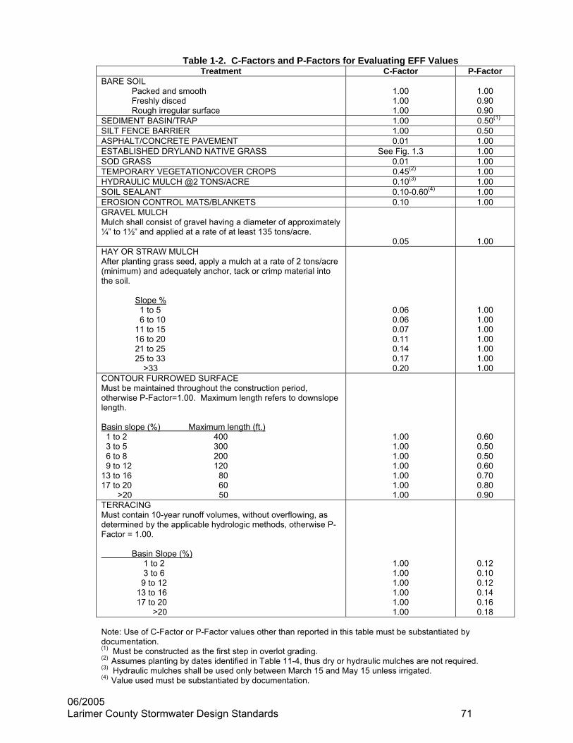
06/2005 Larimer County Stormwater Design Standards 71
Table 1-2. C-Factors and P-Factors for Evaluating EFF Values
Treatment C-Factor P-Factor BARE SOIL Packed and smooth Freshly disced Rough irregular surface
1.00 1.00 1.00
1.00 0.90 0.90
SEDIMENT BASIN/TRAP 1.00 0.50(1)
SILT FENCE BARRIER 1.00 0.50 ASPHALT/CONCRETE PAVEMENT 0.01 1.00 ESTABLISHED DRYLAND NATIVE GRASS See Fig. 1.3 1.00 SOD GRASS 0.01 1.00 TEMPORARY VEGETATION/COVER CROPS 0.45(2) 1.00 HYDRAULIC MULCH @2 TONS/ACRE 0.10(3) 1.00 SOIL SEALANT 0.10-0.60(4) 1.00 EROSION CONTROL MATS/BLANKETS 0.10 1.00 GRAVEL MULCH Mulch shall consist of gravel having a diameter of approximately ¼” to 1½” and applied at a rate of at least 135 tons/acre.
0.05
1.00 HAY OR STRAW MULCH After planting grass seed, apply a mulch at a rate of 2 tons/acre (minimum) and adequately anchor, tack or crimp material into the soil.
Slope % 1 to 5 6 to 10 11 to 15 16 to 20 21 to 25 25 to 33
>33
0.06 0.06 0.07 0.11 0.14 0.17 0.20
1.00 1.00 1.00 1.00 1.00 1.00 1.00
CONTOUR FURROWED SURFACE Must be maintained throughout the construction period, otherwise P-Factor=1.00. Maximum length refers to downslope length. Basin slope (%) Maximum length (ft.) 1 to 2 400 3 to 5 300 6 to 8 200 9 to 12 120 13 to 16 80 17 to 20 60 >20 50
1.00 1.00 1.00 1.00 1.00 1.00 1.00
0.60 0.50 0.50 0.60 0.70 0.80 0.90
TERRACING Must contain 10-year runoff volumes, without overflowing, as determined by the applicable hydrologic methods, otherwise P-Factor = 1.00. Basin Slope (%) 1 to 2 3 to 6 9 to 12 13 to 16 17 to 20 >20
1.00 1.00 1.00 1.00 1.00 1.00
0.12 0.10 0.12 0.14 0.16 0.18
Note: Use of C-Factor or P-Factor values other than reported in this table must be substantiated by documentation. (1) Must be constructed as the first step in overlot grading. (2) Assumes planting by dates identified in Table 11-4, thus dry or hydraulic mulches are not required. (3) Hydraulic mulches shall be used only between March 15 and May 15 unless irrigated. (4) Value used must be substantiated by documentation.

06/2005 Larimer County Stormwater Design Standards 72
Figure 1-3
ESTABLISHED NATIVE GRASS AND C-FACTOR
0
0.05
0.1
0.15
0.2
0.25
0.3
0.35
0 20 40 60 80
ESTABLISHED GROUND COVER (%)
C-FACTOR
100

06/2005 Larimer County Stormwater Design Standards 73
RAINFALL PERFORMANCE STANDARD EVALUATION
STANDARD FORM A
PROJECT: EXAMPLE COMPLETED BY: _________SDH______________________ DATE: ______1/05________
DEVELOPED SUB-BASIN
ERODIBILITY ZONE
Asb(ac)
Lsb(ft)
Ssb(%)
Lb(ft)
Sb(%)
PS (%)
A1
A2
MODERATE
MODERATE
15.8
10.6
26.4
1725
1100
3.0
2.2
1474
2.7
82.1
EXAMPLE OF CALCULATIONS Lb = (1725 X 15.8 + 1100 x 10.6)/26.4 Lb = 1474 feet Sb = (3.0 x 15.8 + 2.2 x 10.6)/26.4 Sb = 2.7% Using Table 1-3, PS = 82.1% (By interpolation)

06/2005 Larimer County Stormwater Design Standards 74
EFFECTIVENESS CALCULATIONS
STANDARD FORM B
PROJECT: EXAMPLE COMPLETED BY: _________SDH_______________________________ DATE: _1/05____
EROSION CONTROL METHOD
C-FACTOR VALUE
P-FACTOR VALUE
COMMENT
BARE SOIL 1.00 1.00 Smooth Condition ROUGHEN GROUND 1.00 0.90
SEDIMENT TRAP 1.00 0.50 For all Sub-basins ROADS/WALKS 0.01 1.00 FOR A2
GRAVEL FILTERS 1.00 0.80 FOR A2 STRAW BALE BARRIER 1.00 0.80 FOR A1
TEMPORARY CROP 0.45 1.00 Spring Wheat HAY MULCH 0.06 1.00
ESTABLISHED GRASS 0.08 1.00 From Figure 1.3
MAJOR BASIN
PS (%)
SUB BASIN
AREA (ac)
CALCULATIONS
A1
15.8
Grass area = 25% x 15.8 ac. = 3.95 ac. Thus, bare ground = 15.8 – 3.95 = 11.85 ac. Roads = 15% x 11.85 ac. = 1.78 ac. Thus, mulch = 11.85 – 1.78 = 10.07 ac. Weighted C-Factor = (0.07 x 3.95 + 0.01 x 1.78 +0.06 x 10.07)/15.8 = 0.06 Weighted P-Factor ={(.50x10.07)+(0.80X1.78)+(1.00X3.95} 15.8 ac = 0.66 EFF = (1 – 0.06 x 0.66) x 100 = 96.0%
A2
10.6
Roads/Walks = 27% x 10.6 ac. = 2.86 ac. Thus, bare ground = 10.6 – 2.86 = 7.74 ac. Rough ground = 45% x 7.74 ac. = 3.48 ac. Smooth ground = 55% x 7.74 ac. = 4.26 ac. Weighted C-Factor = (2.86 x 0.01 + 3.48 x 0.45 + 4.26 x 1.00)/10.6 = 0.55 Weighted P-Factor = {(3.48x0.90)+(4.26x1.00)}/7.74 x 0.80 x 0.50 = 0.38 EFF = (1 – 0.55 x 0.38) x 100 = 79.1%
A 82.4
TOTAL
26.4
EFFnet = (96.0% X 15.8 + 79.1% X 10.6)/26.4 EFFnet = 89.2% Since 89.2% > 82.1%, proposed plan is OK.

06/2005 Larimer County Stormwater Design Standards 75
CONSTRUCTION SEQUENCE
STANDARD FORM C PROJECT _______EXAMPLE_____________________________________ DATE: _____1/01/05 Indicate with bar line when construction events will occur and when BMPs will be installed/removed in relation to the construction phase. CONSTRUCTION PHASE
(Month) 1 2 3 4 5 6 7 8 9 10 11 12
OVERLOT GRADING UTILITIES INSTALLATION ASPHALT/CONCRETE PAVING
WIND EROSION CONTROL
Soil Roughening Perimeter Barrier Additional Barrier Vegetative Methods Soil Sealant Other RAINFALL EROSION CONTROL
STRUCTURAL: Sediment Trap/Basin Inlet Filters Straw Barriers Silt Fence Barriers Sand Bags Bare Soil Preparation Contour Furrows Terracing Other VEGETATIVE: Permanent Seed Planting Mulching/Sealant Temporary Seed Planting Sod Installation Nettings/Mats/Blankets Other

06/2005 Larimer County Stormwater Design Standards 76
RAINFALL PERFORMANCE STANDARD EVALUATION
STANDARD FORM A
PROJECT: COMPLETED BY: ____________________________ DATE: _______________
DEVELOPED SUB-BASIN
ERODIBILITY ZONE
Asb(ac)
Lsb(ft)
Ssb(%)
Lb(ft)
Sb(%)
PS (%)

06/2005 Larimer County Stormwater Design Standards 77
EFFECTIVENESS CALCULATIONS
STANDARD FORM B
PROJECT: COMPLETED BY: _________ ______________________________ DATE: _______________
EROSION CONTROL METHOD
C-FACTOR VALUE
P-FACTOR VALUE
COMMENT
MAJOR BASIN
PS (%)
SUB BASIN
AREA (ac)
CALCULATIONS

06/2005 Larimer County Stormwater Design Standards 78
CONSTRUCTION SEQUENCE
STANDARD FORM C
PROJECT _______________________________________________ DATE: _______________ Indicate with bar line when construction events will occur and when BMPs will be installed/removed in relation to the construction phase.
CONSTRUCTION PHASE (Month)
1 2 3 4 5 6 7 8 9 10 11 12

TABLE 1-3
Rainfall Performance Standards For Larimer County, Colorado FLOW
LENGTH SLOPE (%)
(ft) 0.5 1.0 1.5 2.0 2.5 3.0 3.5 4.0 4.5 5.0 6.0 7.0 8.0 9.0 10.0 20.0 30.0 40.0 50.0100 70.9 74.6 76.8 78.4 79.5 80.3 81.1 81.6 82.1 82.5 83.0 83.4 83.6 83.8 84.0 84.7 84.8 84.9 84.9200 72.0 76.3 78.2 79.5 80.5 81.2 82.1 82.5 82.8 83.2 83.6 83.9 84.0 84.2 84.3 84.8 84.9 84.9 84.9300 72.4 77.0 78.8 80.0 80.9 81.6 82.5 82.8 83.1 83.5 83.8 84.1 84.2 84.3 84.4 84.8 84.9 84.9 85.0400 72.6 77.4 79.1 80.3 81.2 81.8 82.7 83.0 83.3 83.7 84.0 84.2 84.3 84.4 84.5 84.8 84.9 84.9 85.0500 72.7 77.7 79.4 80.5 81.3 81.9 82.8 83.1 83.4 83.8 84.1 84.3 84.4 84.5 84.6 84.9 84.9 85.0 85.0600 72.8 77.9 79.5 80.6 81.4 82.0 83.0 83.2 83.5 83.9 84.1 84.3 84.4 84.5 84.6 84.9 84.9 85.0 - 700 72.8 78.0 79.7 80.8 81.5 82.1 83.0 83.3 83.5 84.0 84.2 84.4 84.5 84.5 84.6 84.9 84.9 85.0 -800 72.7 78.1 79.7 80.8 81.6 82.2 83.1 83.4 83.6 84.0 84.2 84.4 84.5 84.6 84.6 84.9 84.9 85.0 -900 72.7 78.2 79.8 80.9 81.7 82.2 83.2 83.4 83.6 84.1 84.3 84.4 84.5 84.6 84.7 84.9 84.9 85.0 -
1000 72.7 78.3 79.9 81.0 81.7 82.3 83.2 83.5 83.7 84.1 84.3 84.4 84.5 84.6 84.7 84.9 84.9 85.0 -1100 72.6 78.3 79.9 81.0 81.7 82.3 83.3 83.5 83.7 84.1 84.3 84.5 84.6 84.6 84.7 84.9 84.9 - -1200 72.6 78.4 80.0 81.0 81.8 82.3 83.3 83.5 83.7 84.2 84.3 84.5 84.6 84.6 84.7 84.9 84.9 - -1300 72.6 78.4 80.0 81.1 81.8 82.4 83.3 83.6 83.8 84.2 84.4 84.5 84.6 84.6 84.7 84.9 85.0 - -1400 72.5 78.5 80.1 81.1 81.8 82.4 83.4 83.6 83.8 84.2 84.4 84.5 84.6 84.7 84.7 84.9 85.0 - -1500 72.4 78.5 80.1 81.1 81.9 82.4 83.4 83.6 83.8 84.2 84.4 84.5 84.6 84.7 84.7 84.9 85.0 - -1600 72.4 78.5 80.1 81.1 81.9 82.4 83.4 83.6 83.8 84.2 84.4 84.5 84.6 84.7 84.7 84.9 - - -1700 72.3 78.5 80.1 81.2 81.9 82.4 83.4 83.6 83.8 84.3 84.4 84.5 84.6 84.7 84.7 84.9 - - -1800 72.3 78.6 80.1 81.2 81.9 82.4 83.4 83.7 83.8 84.3 84.4 84.5 84.6 84.7 84.7 84.9 - - -1900 72.2 78.6 80.2 81.2 81.9 82.5 83.5 83.7 83.9 84.3 84.4 84.5 84.6 84.7 84.7 84.9 - - -2000 72.2 78.6 80.2 81.2 81.9 82.5 83.5 83.7 83.9 84.3 84.4 84.6 84.6 84.7 84.7 84.9 - - -2500 71.9 78.6 80.2 81.3 82.0 82.5 83.5 83.7 83.9 84.3 84.5 84.6 84.7 84.7 84.8 - - - -3000 71.6 78.8 80.3 81.3 82.0 82.5 83.6 83.8 84.0 84.4 84.5 84.6 84.7 84.7 84.8 - - - -3500 71.4 78.7 80.3 81.3 82.0 82.6 83.6 83.8 84.0 84.4 84.5 84.6 84.7 84.7 84.8 - - - -4000 71.1 78.6 80.3 81.3 82.0 82.6 83.6 83.8 84.0 84.4 84.5 84.6 84.7 84.8 84.8 - - - -4500 70.9 78.6 80.3 81.3 82.0 82.6 83.7 83.9 84.0 84.4 84.6 84.6 84.7 84.8 84.8 - - - -5000 70.6 78.6 80.3 81.3 82.0 82.6 83.7 83.9 84.0 84.4 84.6 84.7 84.7 84.8 84.8 - - - -
06/2005 Larimer County Stormwater Design Standards 79

Table 1-4
Low Rainfall Erodibility Zone Loading Rates (yd3/ac) FLOW LENGTH
SLOPE (%) (ft) 0.5 1.0 1.5 2.0 2.5 3.0 3.5 4.0 4.5 5.0 6.0 7.0 8.0 9.0 10.0 20.0 30.0 40.0 50.00 0.00 0.00 0.00 0.00 0.00 0.00 0.00 0.00 0.00 0.00 0.00 0.00 0.00 0.00 0.00 0.00 0.00 0.00 0.00
100 0.75 1.02 1.29 1.59 1.92 2.27 2.73 3.15 3.59 4.20 5.25 6.42 7.69 9.06 10.50 32.50 63.20 100 141200 0.82 1.22 1.56 1.93 2.34 2.78 3.61 4.18 4.78 6.00 7.55 9.26 11.10 13.20 15.40 45.40 87.70 138 201300 0.84 1.32 1.71 2.13 2.59 3.08 4.17 4.84 5.55 7.27 9.17 11.30 13.60 16.10 18.80 56.20 109 173 245400 0.86 1.40 1.81 2.26 2.75 3.29 4.59 5.33 6.12 8.26 10.40 12.90 15.50 18.40 21.60 64.90 127 201 280500 0.86 1.45 1.88 2.36 2.88 3.44 4.92 5.72 6.58 9.08 11.50 14.20 17.10 20.40 23.80 72.20 142 226 310600 0.86 1.48 1.94 2.43 2.97 3.56 5.19 6.04 6.95 9.78 12.40 15.30 18.50 22.00 25.80 78.60 155 247 ----700 0.87 1.51 1.98 2.49 3.05 3.66 5.42 6.31 7.27 10.40 13.20 16.30 19.70 23.50 27.60 84.30 166 266 ----800 0.86 1.54 2.02 2.54 3.11 3.74 5.62 6.55 7.54 10.90 13.90 17.20 20.80 24.80 29.10 89.30 176 283 ----900 0.86 1.56 2.05 2.58 3.17 3.81 5.79 6.75 7.79 11.40 14.50 18.00 21.80 26.00 30.50 94.00 186 298 ----1000 0.86 1.58 2.07 2.62 3.21 3.87 5.95 6.94 8.00 11.90 15.10 18.70 22.70 27.10 31.80 98.2 195 313 ----1100 0.86 1.59 2.09 2.65 3.25 3.92 6.09 7.10 8.20 12.30 15.70 19.40 23.50 28.10 33.00 102 203 ---- ----1200 0.85 1.60 2.11 2.67 3.29 3.96 6.21 7.25 8.37 12.70 16.10 20.00 24.30 29.00 34.10 106 210 ---- ----1300 0.85 1.61 2.13 2.69 3.32 4.00 6.33 7.39 8.54 13.00 16.60 20.60 25.00 29.90 35.10 109 217 ---- ----1400 0.85 1.62 2.14 2.71 3.35 4.03 6.43 7.52 8.68 13.40 17.00 21.10 25.70 30.70 36.10 112 224 ---- ----1500 0.84 1.63 2.15 2.73 3.37 4.07 6.53 7.63 8.82 13.70 17.40 21.70 26.30 31.40 37.00 115 230 ---- ----1600 0.84 1.63 2.16 2.75 3.39 4.09 6.62 7.74 8.95 13.90 17.80 22.10 26.90 32.10 37.8 118 ---- ---- ----1700 0.84 1.64 2.17 2.76 3.41 4.12 6.70 7.84 9.06 14.20 18.20 22.60 27.50 32.80 38.6 121 ---- ---- ----1800 0.83 1.64 2.18 2.77 3.43 4.14 6.78 7.93 9.17 14.50 18.50 23.00 28.00 33.50 39.40 124 ---- ---- ----1900 0.83 1.65 2.19 2.79 3.44 4.16 6.85 8.02 9.28 14.70 18.80 23.40 28.50 34.10 40.10 126 ---- ---- ----2000 0.83 1.65 2.20 2.80 3.46 4.18 6.92 8.10 9.38 15.00 19.10 23.80 29.00 34.70 40.80 129 ---- ---- ----2500 0.81 1.66 2.22 2.83 3.51 4.25 7.20 8.45 9.78 16.00 20.50 25.50 31.10 37.20 43.90 ---- ---- ---- ----3000 0.79 1.67 2.23 2.86 3.54 4.30 7.42 8.71 10.10 16.80 21.60 26.90 32.80 39.30 46.40 ---- ---- ---- ----3500 0.78 1.67 2.24 2.87 3.56 4.33 7.60 8.93 10.40 17.50 22.50 28.10 34.30 41.10 48.60 ---- ---- ---- ----4000 0.76 1.67 2.24 2.88 3.58 4.35 7.74 9.10 10.60 18.10 23.30 29.10 35.60 42.70 50.40 ---- ---- ---- ----4500 0.75 1.66 2.24 2.88 3.58 4.36 7.86 9.25 10.70 18.70 24.00 30.00 36.70 44.10 52.10 ---- ---- ---- ----5000 0.74 1.66 2.24 2.88 3.59 4.37 7.97 9.38 10.90 19.10 24.60 30.80 37.70 45.30 53.50 ---- ---- ---- ----
06/2005 Larimer County Stormwater Design Standards 80

Table 1-5
Moderate Rainfall Erodibility Zone Loading Rates (yd3/ac) FLOW LENGTH
SLOPE (%) (ft) 0.5 1.0 1.5 2.0 2.5 3.0 3.5 4.0 4.5 5.0 6.0 7.0 8.0 9.0 10.0 20.0 30.0 40.0 50.00 0.00 0.00 0.00 0.00 0.00 0.00 0.00 0.00 0.00 0.00 0.00 0.00 0.00 0.00 0.00 0.00 0.00 0.00 0.00
100 1.84 2.51 3.18 3.91 4.71 5.57 6.71 7.73 8.82 10.30 12.90 15.70 18.90 22.20 25.90 79.70 155 246 346 200 2.00 2.99 3.83 4.75 5.75 6.84 8.86 10.30 11.70 14.70 18.50 22.70 27.30 32.30 37.70 111 215 339 494300 2.07 3.25 4.19 5.22 6.35 7.57 10.20 11.90 13.60 17.80 22.50 27.70 33.40 39.50 46.20 138 268 425 601400 2.10 3.43 4.44 5.55 6.76 8.08 11.30 13.10 15.00 20.30 25.60 31.60 38.10 45.20 52.90 159 311 495 688500 2.12 3.55 4.61 5.78 7.06 8.45 12.10 14.00 16.10 22.30 28.20 34.80 42.10 50.00 58.50 177 348 554 761600 2.12 3.64 4.75 5.97 7.30 8.75 12.70 14.80 17.10 24.00 30.40 37.60 45.50 54.10 63.40 193 379 606 ---- 700 2.12 3.72 4.86 6.11 7.49 8.98 13.30 15.50 17.80 25.50 32.40 40.00 48.50 57.70 67.60 207 408 652 ----800 2.12 3.78 4.95 6.23 7.64 9.18 13.80 16.10 18.50 26.90 34.10 42.20 51.10 60.90 71.50 219 433 694 ----900 2.12 3.83 5.02 6.34 7.78 9.35 14.20 16.60 19.10 28.10 35.70 44.20 53.60 63.80 74.90 231 456 732 ----1000 2.11 3.87 5.08 6.42 7.89 9.49 14.60 17.00 19.60 29.20 37.10 46.00 55.80 66.50 78.10 241 478 768 ----1100 2.10 3.90 5.14 6.49 7.99 9.61 14.90 17.40 20.10 30.20 38.40 47.60 57.80 68.90 81.00 251 498 ---- ----1200 2.10 3.93 5.18 6.56 8.07 9.72 15.20 17.80 20.60 31.10 39.60 49.20 59.70 71.20 83.70 260 516 ---- ----1300 2.09 3.96 5.22 6.61 8.15 9.82 15.50 18.10 21.00 32.00 40.80 50.60 61.40 73.30 86.20 268 534 ---- ----1400 2.08 3.98 5.25 6.66 8.21 9.90 15.80 18.40 21.30 32.80 41.80 51.90 63.10 75.30 88.50 276 550 ---- ----1500 2.07 3.99 5.28 6.71 8.27 10.00 16.00 18.70 21.60 33.50 42.80 53.20 64.60 77.10 90.80 283 566 ---- ----1600 2.06 4.01 5.31 6.75 8.32 10.00 16.20 19.00 22.00 34.20 43.70 54.30 66.10 78.90 92.90 290 ---- ---- ----1700 2.05 4.02 5.33 6.78 8.37 10.10 16.40 19.20 22.30 34.90 44.60 55.40 67.40 80.60 94.80 297 ---- ---- ----1800 2.04 4.04 5.36 6.81 8.41 10.20 16.60 19.50 22.50 35.50 45.40 56.50 68.70 82.10 96.70 304 ---- ---- ----1900 2.03 4.05 5.37 6.84 8.45 10.20 16.80 19.70 22.80 36.10 46.20 57.50 70.00 83.60 98.50 310 ---- ---- ----2000 2.03 4.05 5.39 6.86 8.48 10.30 17.00 19.90 23.00 36.70 47.00 58.40 71.10 85.10 100 315 ---- ---- ----2500 1.98 4.08 5.45 6.95 8.61 10.40 17.70 20.70 24.00 39.20 50.30 62.60 76.30 91.30 108 ---- ---- ---- ----3000 1.94 4.10 5.48 7.01 8.70 10.50 18.20 21.40 24.8 41.30 53.00 66.10 80.60 96.50 114 ---- ---- ---- ---- 3500 1.90 4.10 5.49 7.04 8.75 10.60 18.70 21.90 25.40 43.00 55.20 69.00 84.20 101 119 ---- ---- ---- ---- 4000 1.87 4.09 5.50 7.06 8.78 10.70 19.00 22.30 25.90 44.50 57.20 71.50 87.30 105 124 ---- ---- ---- ---- 4500 1.84 4.08 5.50 7.07 8.80 10.70 19.30 22.70 26.40 45.80 58.9 73.70 90.10 108 128 ---- ---- ---- ---- 5000 1.81 4.07 5.49 7.06 8.81 10.70 19.60 23.00 26.70 47.00 60.50 75.60 92.50 111 131 ---- ---- ---- ----
06/2005 Larimer County Stormwater Design Standards 81

Table 1-6
High Rainfall Erodibility Zone Loading Rates (yd3/ac) FLOW LENGTH
SLOPE (%) (ft) 0.5 1.0 1.5 2.0 2.5 3.0 3.5 4.0 4.5 5.0 6.0 7.0 8.0 9.0 10.0 20.0 30.0 40.0 50.00 0.00 0.00 0.00 0.00 0.00 0.00 0.00 0.00 0.00 0.00 0.00 0.00 0.00 0.00 0.00 0.00 0.00 0.00 0.00
100 2.38 3.25 4.12 5.07 6.10 7.22 8.69 10.00 11.40 13.40 16.70 20.40 24.50 28.8 33.50 103 201 319 448 200 2.60 3.87 4.96 6.15 7.45 8.86 11.50 13.30 15.20 19.10 24.00 29.50 35.40 41.90 48.90 144 279 440 640 300 2.68 4.22 5.43 6.77 8.23 9.81 13.30 15.40 17.70 23.10 29.20 35.90 43.20 51.20 59.90 179 348 551 779 400 2.72 4.44 5.75 7.19 8.76 10.50 14.60 17.00 19.50 26.30 33.20 40.90 49.40 58.60 68.60 207 403 641 891 500 2.74 4.60 5.98 7.50 9.15 11.00 15.70 18.20 20.90 28.90 36.60 45.10 54.50 64.80 75.90 230 451 718 987 600 2.75 4.72 6.16 7.73 9.46 11.30 16.50 19.20 22.10 31.10 39.50 48.70 59.00 70.10 82.20 250 492 785 ---- 700 2.75 4.82 6.30 7.92 9.71 11.60 17.20 20.10 23.10 33.10 42.00 51.90 62.80 74.80 87.70 268 528 845 ---- 800 2.75 4.90 6.41 8.08 9.91 11.90 17.90 20.80 24.00 34.80 44.20 54.70 66.30 78.90 92.60 284 561 899 ---- 900 2.74 4.96 6.51 8.21 10.10 12.10 18.40 21.50 24.80 36.40 46.30 57.30 69.40 82.70 97.10 299 592 949 ----
1000 2.74 5.01 6.59 8.32 10.20 12.30 18.90 22.10 25.50 37.80 48.10 59.60 72.30 86.20 101 313 619 995 ---- 1100 2.73 5.06 6.66 8.42 10.40 12.50 19.40 22.60 26.10 39.10 49.80 61.70 74.90 89.30 105 325 645 ---- ---- 1200 2.72 5.10 6.72 8.50 10.50 12.60 19.80 23.10 26.60 40.30 51.40 63.70 77.40 92.30 108 337 669 ---- ---- 1300 2.71 5.13 6.77 8.57 10.60 12.70 20.10 23.50 27.20 41.40 52.80 65.60 79.60 95.00 112 348 692 ---- ---- 1400 2.69 5.15 6.81 8.64 10.60 12.80 20.50 23.90 27.60 42.50 54.20 67.30 81.80 97.60 115 358 713 ---- ---- 1500 2.68 5.18 6.85 8.69 10.70 12.90 20.80 24.30 28.10 43.50 55.50 68.90 83.70 100 118 367 733 ---- ---- 1600 2.67 5.20 6.89 8.74 10.80 13.00 21.10 24.60 28.50 44.40 56.70 70.40 85.60 102 120 377 ---- ---- ---- 1700 2.66 5.22 6.92 8.79 10.80 13.10 21.30 24.90 28.80 45.30 57.80 71.90 87.40 104 123 385 ---- ---- ---- 1800 2.65 5.23 6.94 8.83 10.90 13.20 21.60 25.20 29.20 46.10 58.90 73.20 89.10 106 125 393 ---- ---- ---- 1900 2.64 5.24 6.97 8.86 11.00 13.20 21.80 25.50 29.50 46.90 59.90 74.50 90.70 108 128 401 ---- ---- ---- 2000 2.63 5.26 6.99 8.90 11.00 13.30 22.00 25.80 29.80 47.60 60.90 75.8 92.20 110 130 409 ---- ---- ---- 2500 2.57 5.29 7.06 9.01 11.20 13.50 22.90 26.90 31.10 50.90 65.10 81.20 98.90 118 140 ---- ---- ---- ---- 3000 2.52 5.31 7.10 9.09 11.30 13.70 23.60 27.70 32.10 53.50 68.60 85.60 104 125 148 ---- ---- ---- ---- 3500 2.47 5.31 7.12 9.13 11.30 13.80 24.20 28.40 33.00 55.80 71.60 89.40 109 131 155 ---- ---- ---- ---- 4000 2.42 5.30 7.13 9.15 11.40 13.8 24.60 29.00 33.60 57.70 74.10 92.70 113 136 160 ---- ---- ---- ---- 4500 2.38 5.29 7.13 9.16 11.40 13.90 25.00 29.40 34.20 59.40 76.40 95.50 117 140 166 ---- ---- ---- ---- 5000 2.34 5.28 7.12 9.16 11.40 13.90 25.30 29.80 34.70 60.90 78.40 98.10 120 144 170 ---- ---- ---- ----
06/2005 Larimer County Stormwater Design Standards 82