addendum no. 1 - coquitlam
TRANSCRIPT

File #: 03-1220-20/21-001/1 Doc #: 4045340.v1
Addendum No. 1 City of Coquitlam
RFP No. 21-001
Civil and Landscape Works for Centennial Synthetic Sports Field Issue Date: April 16, 2021
(consists of 35 pages)
Proponents shall note the following amendments to the RFP documents. REVISIONS R1) ADDITION
R1.1 ) Additional item for Specification: Cast‐in‐place Concrete (Section 03 30 00 SF):
All walls exceeding a height of 0.6 metres shall be protected by an Anti-Graffiti coating. Acceptable suppliers and proprietary products include:
1. CBR 501-AG Anti-Graffiti Coating by Broda Stains and Coatings, as supplied by CBR Products, Cordova, Vancouver BC. (604-254-3325).
R2) DELETION
N/A
R3) REPLACE
On CV‐03 the trench drain leaders have been upgraded from 100Ø to 150Ø.
Detail 4 on CD‐01 has been updated to reflect the 300mm collector.
Detail 6 on CD‐01 has the 10 inch rainbird vault upgraded to a AE concrete 5686 service box.
A note has been added on ESC‐02 to reflect a separate construction gate.
Electrical specifications have been re‐issued. All changed sections have been bubbled in red.
Detail 2 on LD‐02 Chain‐link Vehicle gate height has been updated to 4.00m clearance height.
QUESTIONS AND CLARIFICATIONS
Q1) CV-03 states a 300mm diameter collector. Detail 4 on CD-01 shows a 375mm collector.
Please clarify sizing? A1) The correct size is 300mm. Detail 4 on CD-01 has been updated for clarity.

City of Coquitlam ADD 1- 2 RFP No. 21-001 - Civil and Landscape Works for Centennial Synthetic Sports Field Addendum No. 1
File #: 03-1220-20/21-001/1 Doc #: 4045340.v1
Q2) Drawing CV-03 shows the removal of two pipes from an existing manhole. Detail 7 on CD-01 only shows removal of the 200mm NW pipe. Is the City able to confirm which pipe(s) are to be removed?
A2) The existing 200mm (NW) pipe is to be removed. The existing 150mm (NE) pipe is also to be removed.
City of Coquitlam ADD 1- 3 RFP No. 21-001 - Civil and Landscape Works for Centennial Synthetic Sports Field Addendum No. 1
File #: 03-1220-20/21-001/1 Doc #: 4045340.v1
Q3) Detail 1 and 2 on drawing LD-02 list the mow strip on the fence as being 60mm and 600mm respectively. Are you able to confirm mow strip sizing?
A3) The curb width is 600mm. Detail 1/LD-01 has been updated.
Q4) Where do the tactile ground surface indicators get paid? A4) This item is paid under item 9, Hardscaping.
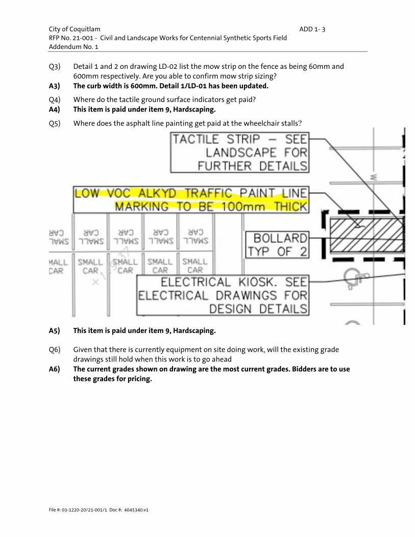
Q5) Where does the asphalt line painting get paid at the wheelchair stalls?
A5) This item is paid under item 9, Hardscaping. Q6) Given that there is currently equipment on site doing work, will the existing grade
drawings still hold when this work is to go ahead A6) The current grades shown on drawing are the most current grades. Bidders are to use
these grades for pricing.

City of Coquitlam ADD 1- 4 RFP No. 21-001 - Civil and Landscape Works for Centennial Synthetic Sports Field Addendum No. 1
File #: 03-1220-20/21-001/1 Doc #: 4045340.v1
Q7) Are you able to confirm that the Contractor is to install the curb along the entire West side of the site per the below screenshot.
A7) The barrier curb is by others. The Contractor is responsible for the rollover curb.
Q8) Drawing L-02 calls out a 600mm wide curb. Drawing CD-01 shows the field curbs as 300mm wide. Are you able to confirm width and depth required of the curb/mow strip?
A8) Details 3 and 5 on CD-01 have been updated to reflect the 600mm curb.
Q9) Detail 1 on LD-07 makes note of perforated metal however there are no specifications for material thickness and the perforation hole pattern or size
A9) Detail 1/LD-07 has been updated to include specifications of perforated metal sheets.
Q10) Detail 1 on LD-07 makes note of the frame for the perforated metal sheets "w clear polycarbonate" which makes no sense. I will assume that the reference to polycarbonate should be detailed.
A10) The reference to polycarbonate for this detail has been removed. There is no polycarbonate on the backstop fencing.
Q11) Detail 1 on LD-07 makes reference to "Tension wire (3 per post between each 1.2m height horizontal rails) to be in-line with tension band spacing.". Can I assume that this in fact should read "Tie wire" not "Tension wire"
A11) This note has been changed to ‘Tie Wire.’
Q12) Multiple details note that "Wire mesh to be installed inside of posts." however the drawing and above noted "tension wire" - "Tie wire" indicate that the mesh runs past the line posts. Need clarification as to which is required.
A12) Clarification: Wire mesh to be installed field side of posts. Mesh to be installed and tied as per specifications.

City of Coquitlam ADD 1- 5 RFP No. 21-001 - Civil and Landscape Works for Centennial Synthetic Sports Field Addendum No. 1
File #: 03-1220-20/21-001/1 Doc #: 4045340.v1
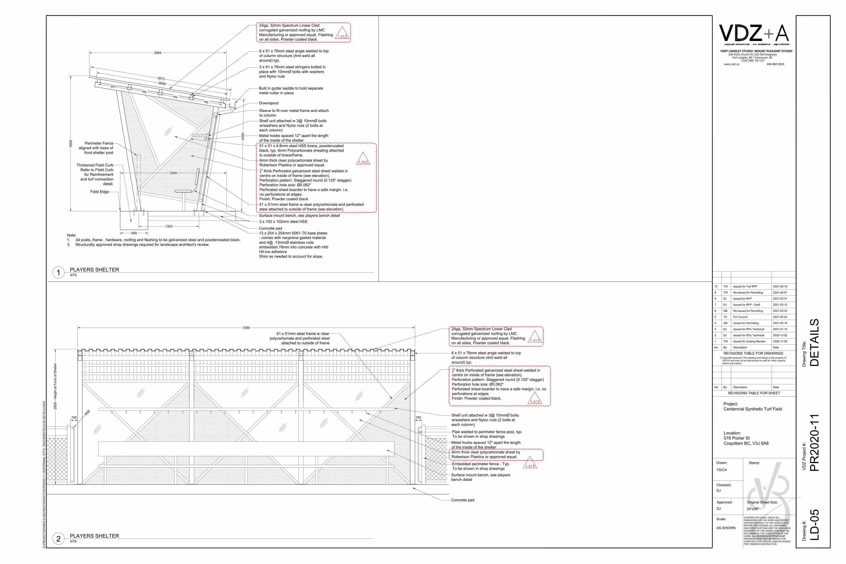
Q13) Details 1 and 2 on LD-05 indicate the use of perforated metal and polycarbonate for the players shelter however no specifications are given for either. This also applies to the "corrugated metal roofing"
A13) LD-05 has been updated stating specifications for these elements.
Q14) Detail 4 on LD-02 for the 1.2m chain link guardrail has conflicting mesh notations. The sectional elevation notes the mesh as being 38 x 38 x 6 gauge and the general fence note 5) states that the mesh is to be 20 x 20 x 9 gauge. Need clarification.
A14) General note 5) has been updated to state 6ga. 38x38mm. See detail 4/LD-02.
Q15) Could you confirm the type of gravel required for around the laterals?
A15) The material is to be MMCD drain rock.
Q16) Are you able to clarify where imported subgrade fill gets paid? Seems to be duplicated in pay items 3 and 6.

City of Coquitlam ADD 1- 6 RFP No. 21-001 - Civil and Landscape Works for Centennial Synthetic Sports Field Addendum No. 1
File #: 03-1220-20/21-001/1 Doc #: 4045340.v1
A16) Imported subgrade fill is to be paid under item 3.
End of Addendum No. 1
Proponents take into account the content of this Addendum in the preparation and submission of the Proposal which will form part of the Contract and should be acknowledged on the Proposal Submission Form.
Upon submitting a Proposal, Proponents are deemed to have received all addenda that are issued and posted on the City’s website and considered the information for inclusion in the Proposal submission.
Issued by:
M. Pain, Purchasing Manager [email protected]

Centennial Secondary Sports Field – Coquitlam Revision: R1
SUPPLEMENTAL SPECIFICATIONS – Lighting & Electrical Print Date: 2021/04/07
Supplemental Specifications
Section Subsection Title Supplementary Specifications
26 56 01 1.0 General
.1 Any reference to Roadway Lighting shall
include Sports Lighting
.2 The work shall include the supply and
installation of sports field lighting as shown on
drawings 7031-20 -01 to 04.
26 56 01 1.10 Inspection
and Testing
.1 Refer to Specifications 16500 and 16470 for
specific testing and inspection requirements.
.2 DMD & Associates Electrical Consultants Ltd.
and VDZ will observe the Contractor's work
3. Contractor shall contact DMD & Associates
Electrical Consultants Ltd at substantial
completion for field review.
4. Contractor shall contact VDZ for conduit and
JB prior to closing the trench.
5. Contractor shall contact Lighting supplier’s
Structural & Geotech Engineer for inspection
of pole foundations, refer to hold point note on
drawings for more information.
26 56 01 1.11 (NEW) Submittals
.1 Contractor shall prepare a set of prints marked-
up to show the "as constructed" installation
upon the completion of the installation. These
mark-ups shall be submitted to DMD.
.2 Submit information as noted in Specifications
Sections 16470 and 16500.
26 56 01 1.12 (NEW) Contractor
Qualifications
.1 All work must be installed by a qualified
electrical contractor, who is required to obtain a
permit from the City/Provincial Electrical
Inspector.
.2 The Contractor shall be a Registered Electrical
Contractor under the provisions of the Electrical
Safety Act.
26 56 01 1.13 (NEW)
Material or
key pattern
supplied by
SD43
.1 Pucklock. The Contractor shall obtain pucklock
or patterns (for puck locks) from the school
district for the base mounted electrical cabinets.
.2 Padlocks. The Contractor shall obtain padlocks
for type 66 jb, receptacles.
26 56 01 1.14 (NEW) Warranty .1 The Contractor shall for a period of one (1)
year after the total performance date, replace or

Centennial Secondary Sports Field – Coquitlam Revision: R1
SUPPLEMENTAL SPECIFICATIONS – Lighting & Electrical Print Date: 2021/04/07
Supplemental Specifications
repair all deficiencies or failures to the
installation free of all charges.
26 56 01 2.1 General .6 All products are indicated on Drawings.
3.1 Execution
.5 No MMCD drawings shall apply for the
installation of sports lighting poles and bases.
.6 The contractor shall use suitable equipment to
excavate the holes for the pre-cast foundations.
Cost for dewatering and sleeving of foundation
shall be borne by the contractor.
.7 The contractor shall employ a BC Land
Surveyor to layout the poles and equipment.
Use the dimensions shown on the construction
drawings. Any digital files that are provided
by DMD or VDZ are for coordination only,
and shall not be used for surveying.
.8 Box and conduit locations shall be staked out
by the contractor and reviewed by VDZ prior
to any excavation.
.9 It is the responsibility of the contractor to set-
up and test the Sports Lighting Controls
system prior to final inspection.
.10 The contractor shall protect all surfaces from
damage caused by equipment and vehicles.
.11 The contractor shall supply and install security
lights on sports light poles.
.12 Contractors to ensure construction area is safe
by the end of the day. Any debris on the field
to be removed by the end of work day.
END OF SECTION
Centennial Secondary Sports Field – Coquitlam Revision: R1
SPECIFICATIONS – Service Cabinet Print Date: 2021/04/07
16470 Service Cabinet
16470 ELECTRICAL CABINETS
PART 1 – GENERAL
1.01 GENERAL
A. This specification shall apply to the design and supply of electrical cabinets which shall
include:
1. Lighting Control Cabinet
B. Cabinets shall include all required equipment, not limited to the main breaker, meter, pull box,
distribution panel(s), transformer, contactors, lighting controls, etc as shown on the drawings.
The cabinet shall be designed to accommodate the Musco Control Link controller.
C. The final cabinet complete with all electrical components shall bear the label of the CSA.
D. The supplier shall design and produce the lighting control cabinet to meet the criteria noted in
this document. The supplier shall be capable of producing a premium grade product, which
meets the quality, fit and finish noted in this document. The use of CNC equipment is
mandatory. The supplier’s shop shall be approved to produce CSA listed products.
E. The cabinet and internal components shall be designed to meet the approval of the local
electrical utility and shall be designed for easy maintenance.
F. The lighting control system (schematic) and power distribution system (one-line diagram) shall
be as noted on the contract electrical drawings.
G. All equipment produced shall meet the requirements of the Canadian Electrical Code.
1.02 ALTERNATE SUBMITTALS
A. Alternate lighting control cabinet suppliers must submit the following for review:
1. Detailed cabinet and door shop drawings showing all fabrication and the layout of all
internal components. Drawings shall be produced using computer drafting format.
2. List of components (by manufacturer and number) and product sheets for each item
3. Cabinet ventilation drawings (sealed by PEng)
B. Approval of alternates shall be granted if the submittal information listed above is complete and
meets the approval of the engineer. To be accepted an alternate submittal must meet or exceed
the Valid Manufacturing product in quality, performance, durability, warranty and shall meet
the requirements of this specification. Where an alternate submittal is not accepted it shall be
returned with a list of deficiencies. Alternates will be reviewed up to two week after award.
Where deficiencies are noted the supplier will have 3 days to resolve the deficiencies to the
satisfaction of the engineer.
C. Acceptance of an alternate does not negate the contractor and suppliers responsibility to meet
the requirements of these specifications.

Centennial Secondary Sports Field – Coquitlam Revision: R1
SPECIFICATIONS – Service Cabinet Print Date: 2021/04/07
16470 Service Cabinet
1.03 QUALITY CONTROL
A. The supplier shall have and maintain a suitable quality control program throughout the contract.
The purpose of the quality control program is to ensure that the product meets the quality
requirements of these qualifications, is delivered on time, and is produced in a cost-effective
manner. The supplier’s quality control program shall apply to all stages of the design,
procurement, manufacturing, testing and delivery of the product.
1.04 WARRANTY
A. General Warranty: The special warranty specified in this Article shall not deprive the Owner of
other rights the Owner may have under other provisions of the Contract Documents and shall
be in addition to, and run concurrent with, other warranties made by the Contractor under
requirements of the Contract Documents.
1. One year parts and labor on all materials from the date of substantial performance
PART 2 – PRODUCTS
2.01 MANUFACTURERS
A. Available Products: Subject to compliance with requirements, that may be incorporated in the
Work include the following products:
1. Valid Manufacturing Ltd. Lighting Control Cabinet (ph 1-250-832-6477), or Approved
Equal
2. Engineer approved alternate (see 1.02 above)
2.02 GENERAL MATERIAL REQUIREMENTS
A. All materials shall be new.
B. Unless otherwise noted, the cabinet shall be fabricated from 5052-H32 sheet aluminum of at
least 1/8-inch thick.
C. All materials shall be corrosion resistant for extended life
2.03 FABRICATION PROCESS
A. The cabinet and door shall be fabricated using CNC controlled equipment.
B. The cabinet and doors shall be fabricated to plus or minus 10 thousands of an inch tolerance for
proper fit.
C. All bending shall be done using a suitable break press.
2.04 CONNECTING HARDWARE
A. All screws, bolts, washers, nuts, etc. shall be stainless steel.
B. All screws shall be stainless steel pan-head machine screw type.

Centennial Secondary Sports Field – Coquitlam Revision: R1
SPECIFICATIONS – Service Cabinet Print Date: 2021/04/07
16470 Service Cabinet
C. Any bolts that are 1/4-20 or larger shall be stainless steel hex head type.
D. No sheet metal or self tapping screws shall be used.
2.05 WELDING
A. All exterior seams shall be of continuously welded construction. All welds shall be free of slag
and spatter. All exterior welds shall be ground smooth.
B. The supplier shall have suitable credentials to weld aluminum and shall adhere to all applicable
ANSI standards.
C. The supplier shall use a suitable welding process and materials.
2.06 DOORS AND HINGES
A. Doors shall be designed for maximum strength and snug fit. Refer to Figures 1 to 5A, which
illustrate the standard required. It is the supplier’s responsibility to design and fabricate the
doors to the fit and finish required in this specification.
B. Doors shall be fabricated out of a single sheet of aluminum and have wrap around return for
strength and fit.
C. Doors shall also have an inner skin for additional strength. The bottom of each door shall have
ventilation holes.
D. Doors shall be fully gasketted against the cabinet.
E. Door hinges shall be positioned so they are hidden behind the door and cannot be accessed with
the door closed. Door hinges are Valid Manufacturing Ltd Model No. HALZF, HALZM,
HALZML, or Approved Equal). A minimum of 4 hinges are required per door.
F. Each door shall have a pneumatic return device (see Figure 4) to control the rate of door open
and close and prevent opening beyond 90 degrees (Faucher Models 777-7727.).
G. Door handles shall be recessed and 3 point contact stainless steel construction (Faucher
Industries No 617-5076 for the handle and 700-5463 for the latch or Approved Equal). The
handles shall latch to the cabinet 16 gauge stainless steel rails and rollers which shall be
fabricated to provide a secure and well sealed attachment to the cabinet (see Figure 3).
H. The exterior of the doors shall have continuous welds.
I. All exterior corners shall be rounded to a minimum radius of 1/8 of an inch. All sharp edges
shall be de-burred to a minimum radius of 1/64 inch in order to reduce hazards to service
personnel.

Centennial Secondary Sports Field – Coquitlam Revision: R1
SPECIFICATIONS – Service Cabinet Print Date: 2021/04/07
16470 Service Cabinet
2.07 CABINET
A. The cabinet and door shall be constructed to meet NEMA 3R standards. The cabinet shall be
made up of the main body, roof section and inner wall. These components shall be welded
together. The cabinet shall be designed for maximum strength and proper fit to the door.

Centennial Secondary Sports Field – Coquitlam Revision: R1
SPECIFICATIONS – Service Cabinet Print Date: 2021/04/07
16470 Service Cabinet
B. Refer to Figures 6 to 11, which illustrate the standard required. It is the supplier’s responsibility
to design and fabricate the cabinet to the fit and finish required in this specification.
C. The cabinet shall be designed to attach to concrete pad via Hilti style drop-in anchors, which
shall be supplied with the cabinet. Supplier shall provide Hilti anchors.
D. The exterior of the cabinet shall have continuous welds.
E. The cabinet main body shall have a wrap around return to accept the door (see Figure 10).
F. The cabinet shall contain 2 internal motion controlled lights (Guard 59-310-Cord C90, or
Approved Equal), a thermostatically controlled fan (ETRI 148 DK-0282-030, 253 CFM), or
Approved Equal), thermostatically controlled 500W heater (Stelpro Heating No. RWF-SA-W
and RWF-501-W, or Approved Equal) and 120V spec grade ground fault duplex receptacle.
G. The cabinet shall be equipped with lifting brackets, which shall be removed after the
installation. The bolts to attach the lifting brackets are shown in Figure 9).
H. All exterior corners shall be rounded to a minimum radius of 1/8 of an inch. All sharp edges
shall be de-burred to a minimum radius of 1/64 inch in order to reduce hazards to service
personnel.
I. Door handle cover shall be hinged and secured with a puck lock (see Figure 5A). Puck lock
supplied by contractor, pattern by the school district 43.
Figure 5A

Centennial Secondary Sports Field – Coquitlam Revision: R1
SPECIFICATIONS – Service Cabinet Print Date: 2021/04/07
16470 Service Cabinet
Centennial Secondary Sports Field – Coquitlam Revision: R1
SPECIFICATIONS – Service Cabinet Print Date: 2021/04/07
16470 Service Cabinet
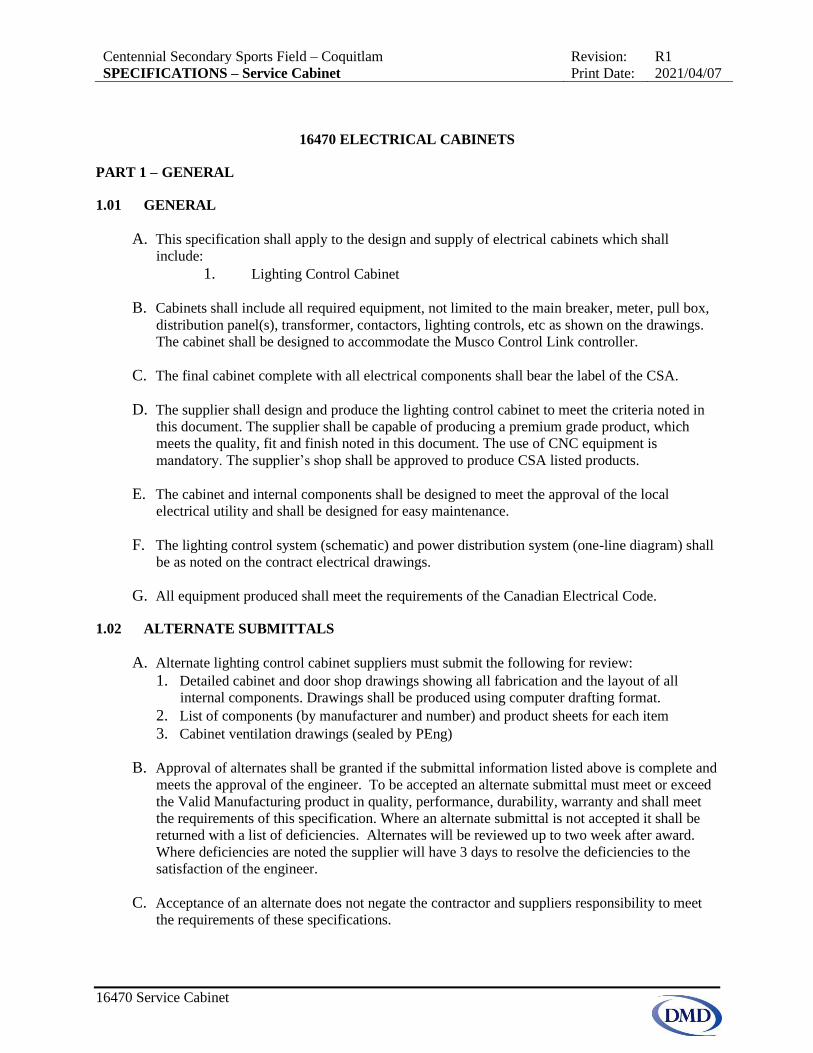
2.08 CABINET VENTILATION
A. The cabinet and doors shall be provided with an engineered ventilation system designed to
move filtered air in through the bottom of the cabinet and out through the top. The internal air
temperature shall be thermostatically controlled to allow the internal equipment to operate
within their recommended operation temperatures and to reduce condensation. The supplier
shall produce details of the ventilation system, how it works, and evidence that the system has
been engineered.
B. The cabinet shall have intake vents in the lower portion of each door and exhaust vents on the
cabinet above the door (see Figures 5, 8 and 12).
C. Ventilation holes shall not be larger than 1/8” diameter to prevent the entry of foreign particles
into the cabinet.
D. Both intake and exhaust vent shall be filtered.
2.09 EQUIPMENT MOUNTING INNER WALL
A. Equipment shall be mounted on an inner panel.
B. Equipment mounting panels shall be constructed from 5052-H32 sheet aluminum at least 1/8
thick.

Centennial Secondary Sports Field – Coquitlam Revision: R1
SPECIFICATIONS – Service Cabinet Print Date: 2021/04/07
16470 Service Cabinet
2.10 FINISH
A. Upon completion of fabrication the cabinet, door and inner wall shall be finished as follows:
1. The surface shall be thoroughly cleaned and degreased using alkaline cleaner and then
rinsed.
2. The surfaces shall be brush blasted to a 1.5 to 2 mil profile.
3. The surfaces shall then be pre-baked and a prime coat shall be electrostatically applied
(DuraCoat zinc epoxy powder primer E-2024-2Z) 2 to 3 mils in thickness.
4. After the prime coat has set, the top coat shall be electrostatically applied (DuraCoat
polyester urethane anti-graffiti type resin for cabinet and doors) 3 to 5mils in thickness.
Color shall be Black RAL 9005 for the cabinet and door and white for the internal back
plane.
5. An independent testing agency shall test and verify the final powder adhesion and finish is
suitable for a long life in an outdoor environment.
6. The final product shall be free of dents, scratches, weld burns and abrasions harmful to its
strength and general appearance.
2.11 GENERAL ELECTRICAL
A. The supplier shall provide equipment layout details with the shop drawings.
B. An inner mask shall be installed to protect personnel from electrical hazard. The mask shall
have cut-outs for circuit breaker toggle mechanisms. Knock outs in the mask shall be provided
for all spare breaker spaces.
C. All equipment shall be mounted on stand-off back panels and shall be secured using 8-32
inserts.

Centennial Secondary Sports Field – Coquitlam Revision: R1
SPECIFICATIONS – Service Cabinet Print Date: 2021/04/07
16470 Service Cabinet
D. All equipment shall be labeled using Lamicoid or vinyl adhesive labels with ½-inch high black
characters on a white background.
E. All panels shall be supplied with the breakers installed.
2.12 METERING
A. Meter shall be located on the interior of the lighting control cabinet, per Figure 15 c/w metering
window.
B. Revenue meter shall be a smart meter with no subscription fees and is capable of remote access
to read the meter data via internet access. Smart meter model to be SQD METSEPM5560 or
equivalent.
2.13 PANELBOARDS
A. The main panel boards shall be supplied based on the panel schedule on the contract drawings.
B. A load center shall also be supplied to feed internal lighting, heater, fan, receptacle, etc in the
lighting control cabinet. This panel may also feed some external devices noted on the contract
drawings.
C. The panel boards and load centers shall be Square D, or approved equal.
D. Panel boards and load centers shall be securely attached to the cabinet back plane and shall be
located for easy access and servicing (see Figure 16).

Centennial Secondary Sports Field – Coquitlam Revision: R1
SPECIFICATIONS – Service Cabinet Print Date: 2021/04/07
16470 Service Cabinet
2.14 CIRCUIT BREAKERS
A. The main breaker shall be electronic trip, molded-case, and clamp-on type (Square D, or
Approved Equal).
B. Branch circuit breakers shall be thermal magnetic trip, molded-case, clamp-on type (Square D
QO, or Approved Equal) to suit the main panel board.
C. The minimum fault current shall be as noted on the contract drawings.

Centennial Secondary Sports Field – Coquitlam Revision: R1
SPECIFICATIONS – Service Cabinet Print Date: 2021/04/07
16470 Service Cabinet
2.15 TRANSFORMERS
A. Transformers shall be dry type (Delta ET series, or Hammond Power Solutions, or Approved
Equal). Transformer size and voltage shall be as noted on the contract drawings.
B. Transformer shall be mounted and attached in a suitable location for easy access.
2.16 GROUNDING
A. The grounding system shall be designed to meet all CSA standards and any codes and local
utility standards.
B. The grounding system shall be designed as part of the power distribution system.
2.17 SURGE PROTECTION
A. The surge protective device (SPD) shall be Type 1 with a minimum of 40kA nominal discharge
current rating in accordance with ANSI/UL 1449 and IEEE C62.
B. Surge protective device shall be Schneider QO plug-on, Mersen STP DIN-rail mounted or
Approved Equal. Voltage and number of poles shall be as noted on the contract drawings.
C. Shall contain a built-in LED indicator that notifies when replacement of the module is needed.
2.18 LIGHTING CONTROL CABINET
A. The lighting controls shall be Musco Control Link systems.

Centennial Secondary Sports Field – Coquitlam Revision: R1
SPECIFICATIONS – Service Cabinet Print Date: 2021/04/07
16470 Service Cabinet
2.19 PULL BOXES AND WIREWAYS
A. Pull boxes and wire ways shall be provided for easy field wiring and trouble shooting. Pull box
size and locations shall meet utility standards and be located on the inside of the cabinet.
B. All wire ways and pull boxes shall have removable covers.
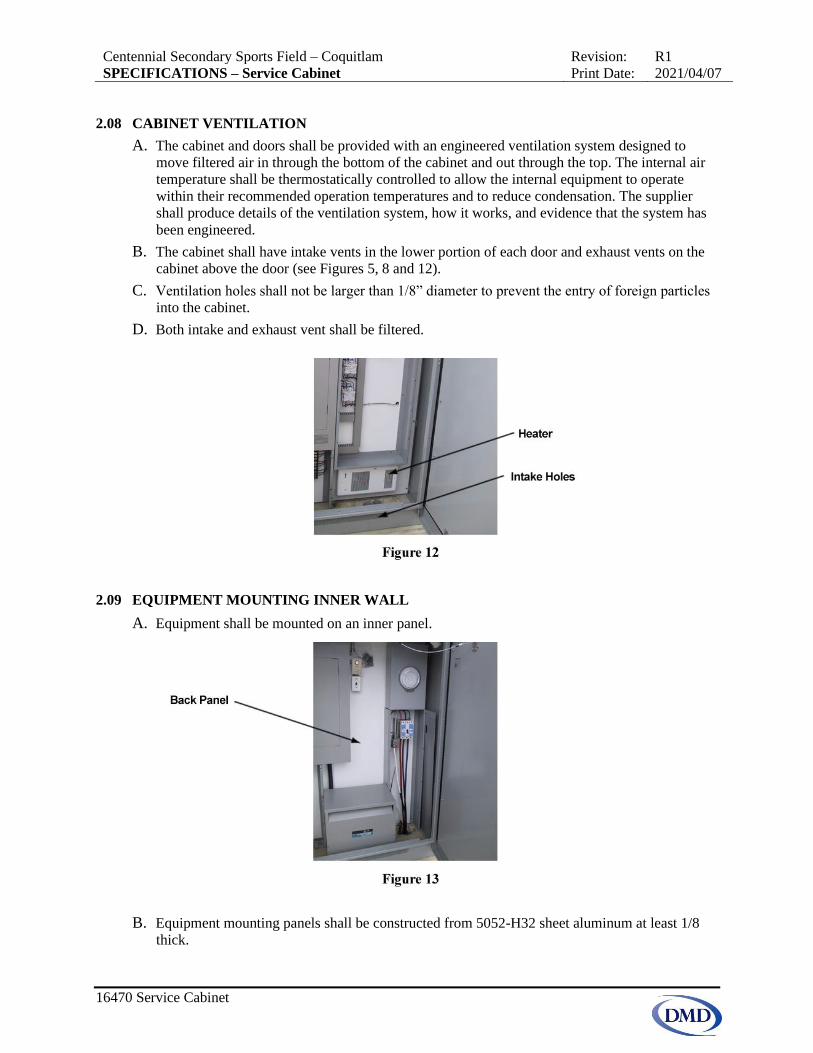
2.20 WIRING
A. All wiring shall be neatly grouped bundled and ty-rapped as shown below.
Centennial Secondary Sports Field – Coquitlam Revision: R1
SPECIFICATIONS – Service Cabinet Print Date: 2021/04/07
16470 Service Cabinet
B. All conductors shall be stranded copper RW90 insulation.
C. Provide 8-32 inserts and ty-rap mounts for the attachment of wiring.
D. Wiring and terminal blocks shall be labeled according to the conventions shown in Figures 22
and 23.
E. All wiring shall meet CEC standards.
2.21 TERMINAL BLOCKS
A. Terminal blocks in the contactor cabinet shall be din rail mounted as shown in figure 22 above.
B. Output wiring shall be connected via terminal blocks to accept aluminum or copper field
wiring.
C. Terminals for bonding conductors will also be required.
D. Terminal blocks shall be rated for minimum of 75 degrees Celsius.

Centennial Secondary Sports Field – Coquitlam Revision: R1
SPECIFICATIONS – Service Cabinet Print Date: 2021/04/07
16470 Service Cabinet
2.22 LABELING
A. All products shall be labeled (inside) with the supplier’s company name, model number, panel
rating and the date of manufacture.
B. The supplier shall also provide adhesive Lamacoid or vinyl labels on the inside of each cabinet
for each component. Each contactor and output circuit shall also be labeled in accordance with
the suppliers lighting design.
C. All ID labels shall have ¼” to ½” high black characters on a white background.
D. All wiring shall be labeled with computer generated sleeve type wire markers.
E. Refer to drawings for push button Lamacoid labels.
2.23 TESTING AND INSPECTION
A. The supplier shall test all equipment circuits and lighting controls prior to shipment. Test
results shall be provided upon request.
B. The owner reserves the right to inspect the completed product prior to packaging and shipping.
The supplier shall advise the engineer a minimum of 5 working days prior to shipping for
inspection.
2.24 PACKAGING
A. Each cabinet shall each be lag bolted to two 4” x 4” posts along the shorter sides of the cabinet
to be used for support when kiosk is being lifted or moved.
B. Any product damaged in shipping shall be repaired or replaced at no extra cost to the Owner.

Centennial Secondary Sports Field – Coquitlam Revision: R1
SPECIFICATIONS – Service Cabinet Print Date: 2021/04/07
16470 Service Cabinet
PART 3 – EXECUTION
3.01 INSTALLATION
A. Set units on concrete foundation and attach with drop in anchors supplied with cabinet. Seal
cabinet to concrete with suitable sealant.
B. Conduits shall be located as shown on the supplier’s conduit layout drawing.
C. Concrete Foundations:
1. Size as noted on the contract drawings
2. Concrete shall have a minimum compressive strength of 28Mpa at 28 days.
3. Comply with details on the contract drawings for reinforcing, attachment, etc.
4. Trowel finish and rub smooth parts exposed to view. Top of concrete shall be level.
Chamfer all exposed edges.
5. Conduits shall be as noted on the contract drawings. Supplier to provide template locating
conduits to suit the cabinet
3.02 GROUNDING
A. Install all grounding and bonding in accordance with CEC and the contract drawings.
3.03 FIELD QUALITY CONTROL
A. Inspect each installed unit for damage. Replace damaged components.
B. Give advance notice of dates and times for field tests.
C. Provide instruments to make and record test results.
D. Tests and Observations: Supplier shall test all circuits and controls prior to shipping.
E. Replace or repair damaged and malfunctioning units, make necessary adjustments, and retest.
Repeat procedure until all units operate properly.
END OF SECTION

Centennial Secondary Sports Field – Coquitlam Revision:
SPECIFICATIONS – Sports Lighting Print Date: 2021/03/09
16500 Sports Lighting System
16500 SPORTS LIGHTING
PART 1 – GENERAL
1.01 GENERAL
A. These specifications cover the supply and installation of the sports lighting system
which includes:
1. Galvanized steel poles and fixture mounting cross arms
2. Wiring from cabinets to fixtures
3. Foundations and related engineered design drawings and letters of assurance
for structural and geotechnical (schedules B and C forms)
4. Security Features – Poles foundations shall have tamper proof hand-holes with
stainless steel banding, pole mounted electrical cabinets shall be heavy duty
lock brackets
B. The sports lighting equipment shall meet the requirements of these specifications and
the DMD contract drawings.
C. Abbreviations:
1. ANSI American National Standards Institute
2. CEC Canadian Electrical Code
3. NEMA National Electrical Manufacturers Association
4. IES Illuminating Engineering Society
5. CSA Canadian Standards Association
6. UBC Uniform Building Code
D. Alternate lighting systems may be considered and shall be quoted as an alternate. No
alternate approvals will be granted prior to bid close
1.02 CSA
A. All equipment shall be CSA approved and/or cUL Listed.
1.03 DESIGN CRITERIA
A. The sports lighting system shall meet the following criteria:
1. Fixtures: max 1430W LED.
2. Maximum Load: 33.2 kW. Higher loads will require electrical redesign and
larger wire which shall be factored into the cost
3. Voltage: System voltages are to be 347/600V, 3 phase.
4. Pole Sizes: Shall be as shown on DMD electrical drawings.
5. Pole Locations: Are shown on DMD electrical drawings.
6. Light Loss Factor (LED): Average maintained horizontal illuminance light
levels shall be lumen deprecation via IES TM-21 tests, dirt factor (0.95), and
ambient temperature factor. If light loss factor is achieved via changing driver
current the supplier must submit data to prove light levels can be maintained.

Centennial Secondary Sports Field – Coquitlam Revision:
SPECIFICATIONS – Sports Lighting Print Date: 2021/03/09
16500 Sports Lighting System
7. Minimum Maintained Average Horizontal Illuminance:
a) Football, soccer, and field hockey shall not be less than 300 Lux
8. Maximum to Minimum Uniformity (on field):
a) Football and soccer shall not exceed 2.5:1
b) Field hockey shall not exceed 3.0:1
9. Grid Spacing – As per IESNA RP-6 (current edition).
10. Foundations: Shall be such that their excavation has a minimum impact on the
surrounding areas.
B. The above lighting criteria shall be read in conjunction with the contract drawings.
1.04 WARRANTY
A. The equipment shall include the following warranty:
1. A full written parts and labor warranty for a period of 25 years. The supplier will
exercise all reasonable efforts to perform service under this Contract, in an
expeditious manner, as laid out in the written warranty, but will not be
responsible for delays or failure in performing such services caused by
conditions, acts, or other causes beyond its control. The warranty period shall
start from the date of shipment from the factory.
2. Average constant light levels shall be guaranteed to +/- 10% of the design criteria
for the warranty period.
1.05 PERFORMANCE GUARANTEE
A. The lighting supplier shall provide a written guarantee for the performance of the lighting
system relative to the information provided. The supplier must also commit in writing to
making any repairs and/or modifications to the components supplied if they don’t meet
the performance requirements noted in these specifications.
1.06 SUBMITTALS AFTER AWARD
A. Prior to production the supplier shall submit the following information to DMD for
review:
1. Light level calculations on the fields and off the fields (spill lighting in vertical
Lux and Candle-power;
2. Aiming diagram;
3. Lighting control system operations and diagrams and cabinet details specific to
this project;
4. Foundation design drawing (complete with engineer’s seal, registered in the
province of BC);
5. Warranty information;
6. Installation instructions and O&M information;
7. Production schedule.
B. DMD shall review and provide comments. Supplier shall make revisions prior to
production.

Centennial Secondary Sports Field – Coquitlam Revision:
SPECIFICATIONS – Sports Lighting Print Date: 2021/03/09
16500 Sports Lighting System
PART 2 – PRODUCTS
2.01 MANUFACTURERS
A. Available Products: Subject to compliance with requirements, products that may be
incorporated in the work include:
1. Musco Lighting LED and the 25 year service plan
B. Alternate lighting systems may be considered and shall be quoted as an alternate. No
alternate approvals will be granted prior to bid close
2.02 POLES
A. Poles shall be:
1. Multi-section round tapered steel to ASTM-A595.
2. Each section shall slip fit together over the lower section by at least 1.5 times
the diameter
3. Slip-fit over pre-cast concrete or galvanized steel foundation
4. Include all couplings, brackets, wire ways and fittings as required
5. All welding shall be to the highest standard and shall be performed by AWS
Certified welders
6. Hot dip galvanized after fabrication and welding in accordance with ASTM-
A123
7. Designed to CSA standards (CAN/CSA S6-06) for the required mean 50 year
return wind pressure of 480 Pascals for the Coquitlam area. Pole shop
drawings shall be sealed by a P.Eng and shall be supplied upon request.
2.03 CROSS ARMS AND FIXTURES
A. Fixtures shall be mounted on cross arms. The fixture and cross arm assembly shall be
designed to CSA standards for a required mean wind pressure of 480 Pascals.
B. Cross arms shall be as follows:
1. Designed to support the required fixtures and attach to the poles
2. Include all couplings, brackets, wire ways and fittings as required
3. All welding shall be to the highest standard and shall be performed by AWS or
CWB Certified welders
4. Hot dip galvanized after fabrication and welding in accordance with ASTM-
A123
5. Designed to accept wiring harness
C. Fixtures shall attach to cross arms. Fixtures shall be as follows:
1. Designed specifically for sports lighting.
2. Fixtures shall be LED.
3. Attach to the cross arm with an adjustable bracket. This bracket shall be set at
the factory to the required fixture aiming. The bracket shall lock in and retain
the factory aiming position.
4. The lens, seal and reflector shall prevent water entry into the reflector

Centennial Secondary Sports Field – Coquitlam Revision:
SPECIFICATIONS – Sports Lighting Print Date: 2021/03/09
16500 Sports Lighting System
5. All attachment hardware, nuts, bolts and washers shall be stainless steel
6. Have external visor, which wraps around the fixture to minimize light trespass.
2.04 ELECTRICAL CABINETS
A. The electrical cabinet shall attach to the pole at approximately 3m above finished
grade. The electrical cabinet shall be galvanized steel or powder coated aluminum
finish. The cabinet shall be a NEMA 3R rated enclosure, which shall securely attach to
the pole with stainless steel hardware. The cabinet shall have corrosion-resistant
hinges, be of vandal resistant and shall be designed to accept a padlock. The cabinet
shall have a suitable wire way into the pole. The cabinet shall house the following:
1. Driver
2. Surge protection
3. Terminal blocks- For wiring from the breaker to the individual fuses
4. Wiring- Shall have suitable temperature rating and shall be color coded
5. Disconnect Device- To accept incoming circuits. The breaker shall be the
landing point for the incoming circuits and shall act as a local disconnect
device.
6. Fuses- Each fixture shall have individual fusing
B. Nuts, bolts and internal hardware shall be corrosion resistant
C. All equipment shall be fully assembled, neatly arranged and wired. All wiring shall be
labeled for easy field tracing. Components shall be mounted for easy removal and
replacement.
2.05 WIRING
A. Wiring from the electrical cabinet to the fixtures shall be supplied as a pre-wired
harness with CSA recognized plug in connectors. All wiring shall be labeled for easy
trouble-shooting.
B. Wiring harness shall have abrasion bumpers or wrapping to prevent chaffing against
the pole.
C. Wiring shall attach to a suitable strain reducing device at the top of the pole.
2.06 MOUNTING HARDWARE
A. All external mounting hardware shall be aluminum, stainless steel or galvanized steel.
Internal mounting hardware shall be stainless steel or cad plated.
2.07 FOUNDATIONS
A. Foundation shall be design by supplier based on soils report (attached). All foundations
including rebar and backfill shall be designed and signed and sealed by the supplier’s
professional engineers to suit the soils conditions and pole loading.

Centennial Secondary Sports Field – Coquitlam Revision:
SPECIFICATIONS – Sports Lighting Print Date: 2021/03/09
16500 Sports Lighting System
B. Pre-cast concrete foundations shall be designed to support the pole when installed in
the excavation and backfilled with concrete. The foundation shall have suitable conduit
entrance holes and wiring access hand holes and shall have a suitable wire way into the
pole.
C. Signed and sealed Schedule B and C-B letters of assurance shall be provided by
geotechnical and structural engineers for pole foundations at the supplier’s expense.
PART 3 – EXECUTION
3.01 STORAGE
A. If required the contractor shall store luminaires, cross arms, wiring and electrical
enclosures off-site until they are ready for assembly and erection. Under no
circumstances shall any of these items be stored on site when the contractor is not
present.
B. Poles may be stored on-site (for a short time period) if they do not impact the day-to-
day operation of the facility. The contractor is responsible for any damage or theft to
any materials left on-site. Pole shall be placed on suitable supports off the ground.
3.02 INSTALLATION
A. The sports lighting equipment shall be installed in accordance with supplier’s
installation instructions.
B. Equipment shall be off loaded and installed in accordance with the supplier’s
installation instructions.
C. All pole shall be installed plumb.
D. Upon acceptance from the owners geotechnical engineer the foundation shall be
backfilled with concrete. Contractor shall arrange for and coordinate geotechnical
inspections.
E. Foundations shall be installed as noted on supplier’s foundation design drawings.
3.03 FIELD QUALITY CONTROL
A. Inspect each installed unit for damage. Replace damaged fixtures and components
prior to installation.
B. Give advance notice of dates and times for field tests.
C. Tests and Observations:
1. Prior to pole erection all sports lights shall be checked by energizing circuits
with suitable power source.

Centennial Secondary Sports Field – Coquitlam Revision:
SPECIFICATIONS – Sports Lighting Print Date: 2021/03/09
16500 Sports Lighting System
2. After installation and connection of sports lights to their permanent power
supply the contractor shall verify supply voltages and current at the disconnect
switch in the electrical enclosure and at the main breaker. Measurements shall
be taken phase to phase and phase to neutral (as required).
3.04 INDEPENDENT TESTING AND OBSERVATIONS
A. DMD will field measure and document the on-field illumination levels and uniformities
in accordance with IESNA LM-5. Off-site spill light levels will also be measured along
the defined boundary line.
B. If the field survey results do not meet the specified illumination requirements. The
supplier shall rectify the problem at no cost to the client. In the event that local
residents have complaints about the spill and glare from the lights even though the
supplier has met the intent of the specification the supplier will provide re-aiming
services to reduce the spill and glare to the best of their abilities with no guarantee that
it will appease the local residents and meet the field illumination requirements. This
additional service will be at no cost to the client if no additional equipment is required.
C. Following installation DMD will undertake a detailed review of the lighting installation
and will note all deficiencies to be corrected. Where deficiencies are noted as a result of
inaccurate or improper installation the installing contractor will be required to correct
all noted deficiencies, in an expeditious manner. Where the noted deficiencies are
related to the materials and workmanship of the lighting equipment itself the supplier
will correct the deficiencies as per the warranty agreement.
D. Sports light pole foundation installation monitored by the contractor’s geotechnical
engineer. All installations shall meet the satisfaction of the geotechnical engineer.
Schedule B and C forms shall be provided for structural and geotechnical.
END OF SECTION

Drawn:
VD
Z P
ro
je
ct #
:
No.
Dra
win
g T
itle
:
REVISIONS TABLE FOR DRAWINGS
Description Date
Scale:
Approved:
Dra
win
g #
:
Checked:
Stamp:
CONTRACTOR SHALL CHECK ALL
DIMENSIONS ON THE WORK AND REPORT
ANYDISCREPANCY TO THE CONSULTANT
BEFORE PROCEEDING. ALL DRAWINGS
AND SPECIFICATIONS ARE THE EXCLUSIVE
PROPERTY OF THE OWNER AND MUST BE
RETURNED AT THE COMPLETION OF THE
WORK. ALL REZONING/DP/PPA/FHA/BP
DRAWINGS MUST NOT BE PRICED FOR
CONSTRUCTION UNLESS LABELED ISSUED
FOR TENDER/CONSTRUCTION.
By:
24"x36"
Original Sheet Size:
Copyright reserved. This drawing and design is the property of
VDZ+A and may not be reproduced or used for other projects
without permission.
No. Description DateBy:
REVISIONS TABLE FOR SHEET
100-9181 Church StFort Langley, BC
V1M 2R8
102-355 KingswayVancouver, BCV5T 3J7
www.vdz.ca 604-882-0024
FORT LANGLEY STUDIOMOUNT PLEASANT STUDIO
Location:
578 Poirier St
Coquitlam BC, V3J 6A8
Project:
Centennial Synthetic Turf Field
1 Issued for Costing Review 2020-11-05TW
PR
20
20
-1
1
2 Issued for 50% Technical 2020-12-02DJ
3 Issued for 95% Technical 2021-01-15DJ
4 Issued for Permitting 2021-02-16GB
5 For Council 2021-02-22TS
6 Re-issued for Permitting 2021-02-24GB
7 Issued for RFP - Draft 2021-03-12DJ
8 Issued for RFP 2021-03-31DJ
9 Re-issued for Permitting 2021-04-01TW
10 Issued for Turf RFP 2021-04-19TW
Z:\P
RO
JE
CT
S\P
AR
KS
&
R
EC
RE
AT
IO
N\A
CT
IV
E\P
R2020-11 C
EN
TE
NN
IA
L S
TF
\5. D
WG
\S
HE
ET
S\C
D-01 - D
ET
AILS
.D
WG
1:250
CD
-0
1D
ET
AIL
S
GB
DJ
TS
TW
1 2021-04-16TW Addendum #1

B
B
B
B
DF
B
B
B
B
B
B
B
B
B
B
B
B
B
B
B
B
B
H/T H/T H/T
Drawn:
VD
Z P
ro
je
ct #
:
No.
Dra
win
g T
itle
:
REVISIONS TABLE FOR DRAWINGS
Description Date
Scale:
Approved:
Dra
win
g #
:
Checked:
Stamp:
CONTRACTOR SHALL CHECK ALL
DIMENSIONS ON THE WORK AND REPORT
ANYDISCREPANCY TO THE CONSULTANT
BEFORE PROCEEDING. ALL DRAWINGS
AND SPECIFICATIONS ARE THE EXCLUSIVE
PROPERTY OF THE OWNER AND MUST BE
RETURNED AT THE COMPLETION OF THE
WORK. ALL REZONING/DP/PPA/FHA/BP
DRAWINGS MUST NOT BE PRICED FOR
CONSTRUCTION UNLESS LABELED ISSUED
FOR TENDER/CONSTRUCTION.
By:
24"x36"
Original Sheet Size:
Copyright reserved. This drawing and design is the property of
VDZ+A and may not be reproduced or used for other projects
without permission.
No. Description DateBy:
REVISIONS TABLE FOR SHEET
100-9181 Church StFort Langley, BC
V1M 2R8
102-355 KingswayVancouver, BCV5T 3J7
www.vdz.ca 604-882-0024
FORT LANGLEY STUDIOMOUNT PLEASANT STUDIO
Location:
578 Poirier St
Coquitlam BC, V3J 6A8
Project:
Centennial Synthetic Turf Field
1 Issued for Costing Review 2020-11-05TW
PR
2020-11
2 Issued for 50% Technical 2020-12-02DJ
3 Issued for 95% Technical 2021-01-15DJ
4 Issued for Permitting 2021-02-16GB
5 For Council 2021-02-22TS
6 Re-issued for Permitting 2021-02-24GB
7 Issued for RFP - Draft 2021-03-12DJ
8 Issued for RFP 2021-03-31DJ
9 Re-issued for Permitting 2021-04-01TW
10 Issued for Turf RFP 2021-04-19TW
Z:\P
RO
JE
CT
S\P
AR
KS
&
R
EC
RE
AT
IO
N\A
CT
IV
E\P
R2020-11 C
EN
TE
NN
IA
L S
TF
\5. D
WG
\S
HE
ET
S\C
V-03 - S
ER
VIC
IN
G P
LA
N.D
WG
1:250
CV
-03
SE
RV
IC
IN
G P
LA
N
NORTH
GB
DJ
TS
TW

H/T H/T H/TH/T
Drawn:
VD
Z P
ro
je
ct #
:
No.
Dra
win
g T
itle
:
REVISIONS TABLE FOR DRAWINGS
Description Date
Scale:
Approved:
Dra
win
g #
:
Checked:
Stamp:
CONTRACTOR SHALL CHECK ALL
DIMENSIONS ON THE WORK AND REPORT
ANYDISCREPANCY TO THE CONSULTANT
BEFORE PROCEEDING. ALL DRAWINGS
AND SPECIFICATIONS ARE THE EXCLUSIVE
PROPERTY OF THE OWNER AND MUST BE
RETURNED AT THE COMPLETION OF THE
WORK. ALL REZONING/DP/PPA/FHA/BP
DRAWINGS MUST NOT BE PRICED FOR
CONSTRUCTION UNLESS LABELED ISSUED
FOR TENDER/CONSTRUCTION.
By:
24"x36"
Original Sheet Size:
Copyright reserved. This drawing and design is the property of
VDZ+A and may not be reproduced or used for other projects
without permission.
No. Description DateBy:
REVISIONS TABLE FOR SHEET
100-9181 Church StFort Langley, BC
V1M 2R8
102-355 KingswayVancouver, BCV5T 3J7
www.vdz.ca 604-882-0024
FORT LANGLEY STUDIOMOUNT PLEASANT STUDIO
Location:
578 Poirier St
Coquitlam BC, V3J 6A8
Project:
Centennial Synthetic Turf Field
1 Issued for Costing Review 2020-11-05TW
PR
2020-11
2 Issued for 50% Technical 2020-12-02DJ
3 Issued for 95% Technical 2021-01-15DJ
4 Issued for Permitting 2021-02-16GB
5 For Council 2021-02-22TS
6 Re-issued for Permitting 2021-02-24GB
7 Issued for RFP - Draft 2021-03-12DJ
8 Issued for RFP 2021-03-31DJ
9 Re-issued for Permitting 2021-04-01TW
10 Issued for Turf RFP 2021-04-19TW
Z:\P
RO
JE
CT
S\P
AR
KS
&
R
EC
RE
AT
IO
N\A
CT
IV
E\P
R2020-11 C
EN
TE
NN
IA
L S
TF
\5. D
WG
\S
HE
ET
S\E
SC
-02 - E
SC
P
LA
N - S
TA
GE
1.D
WG
1:250
ES
C-02
ES
C P
LA
N - S
TA
GE
1
NORTH
GB
DJ
TS
TW
1 2021-04-16TW Addendum #1

L
C
91
5
2400 MAX
12
00
50
300
L
C
Note:
1. Post spacing shall be equidistant to a maximum of
2400mm o.c. unless noted otherwise on layout and
materials plan.
2. Wire mesh to be galvanized.
3. All posts, gate posts, rails and hardware to be
galvanized and powder-coated black.
4. Provide shop drawings of fence and gates for approval
by Landscape Architect.
5. All Dimensions are in mm unless noted.
6. All posts, gate posts, rails and hardware to be
galvanized and powder-coated black.
50
15
0
300
91
5
15
0
20mm X 5mm Beveled edge tension
bar wherever fabric ends, typ.
6 gauge galvanized, black vinyl-coated steel wire woven
into 38 x 38mm size diamond pattern mesh, typ.
Vinyl coated galvanized steel tie wire (9 ga.) tied at
every second knuckle
48mm O.D. Top rail
60mm O.D. Line post with dome cap, typ.
Concrete footing 300mmØ 915mm depth, typ.
Concrete sonotube.
150mm min of 95% MPD compacted aggregate
base course
tension bands wherever fabric
600mm wide concrete curb. (finished grade).
48mm O.D. Bottom rail
150mm depth 19mm minus aggregate
base compacted to 95% MPD
76mm O.D. corner and end post with dome cap, typ.
Tension bands
Tension wire (3 per post between each
1.2m height horizontal rails) to be
in-line with tension band spacing.
Control joint tooled at every fence post to
edge of curb (perpendicular to field).
1235
863
250
Lockable fence latch
48mm (2") O.D. Cross Brace
48mm (2") O.D. lateral, typ.
3600
Heavy duty, self closing hinge
(gravity) - Typ. each panel for
both gates. No spring-loaded
hinges permitted. Contractor to
provide shop drawing.
1566
Adjacent perforated panel
(optional item)
10mm X 5mm Beveled
edge tension bands (13
ga.) wherever fabric ends
100mm (4") O.D. gate
posts
6 gauge galvanized steel
wire woven into 38mm x
38mm size mesh
VSP W-12X3-VSP-PBB-3/4"
305mm x 76mm tires (2),
complete with bracket and
and locking mechanism. See
left for attachment details.
Gate to swing 100° max
Concrete footing.
Indicative only.
Refer to
Backstop
elevations and
footing details
Top of Footing
168.3mm O.D. (6
5
8
")
Schedule 40, 50ksi
(345 MPa) ASTM
F1083 Pipe.
1250
60mm O.D. top rail.
48mm (2") O.D. Cross Brace
4000
1289
1219
1137
50
GENERAL GATE NOTES:
1) Contractor to provide shop detail drawings for fencing and gates to Landscape
Architect for approval prior to manufacturing.
2) Refer to specification for clarification.
3) All dimensions are in mm unless noted.
4) All interior gates to open 180°.
5) All posts, gate posts, rails and hardware to be galvanized and powder-coated black.
1200
300
915
150
300
915
150
10mm X 5mm Beveled edge
tension bands wherever fabric
ends
Corner and end posts caps to
be welded
6 gauge galvanized black
vinyl-coated steel wire
woven into 38 x 38mm size
diamond pattern mesh, ties
at every knuckle
48mm O.D. gate frame
Concrete footing 300mmØ
915mm depth, typ.
Concrete sonotube.
150mm min of 95% MPD
compacted aggregate
base course
Latch - lockable drop pin
and Gate Stop. Gate to
swing open as per plan.
600mm wide concrete curb.
Refer to detail.
76mm O.D. gate post with
dome cap, typ.
150mm depth 19mm minus
aggregate base compacted
to 95% MPD
Connector band
Hinge
Proposed Horizontal
Sched 40, OD Ø48m rails
SECTIONAL ELEVATION
SCALE 1:20
Surface mounted to top of wall
Welded Dome post cap, 1" deep
GENERAL FENCE NOTES:
1) All fence posts & rails to be schedule 40 galvanized pipe, black powder coat finish.
2) All fittings must be galvanized steel or aluminum powder coated and welded in place, black powder coat finish.
3) All intermediate, top and bottom rails shall be saddle notched and welded to vertical posts, black powder coat finish.
4) Any areas affected by cutting, welding, etc. shall be ground smooth and painted with two coats of black galvicon gloss
(zinc paint).
5) All mesh to be 6 ga. black vinyl coated with 38 x 38mm openings.
6) All ties to be 9 ga. black vinyl coated and located at every 2nd knuckle on rails and posts
7) Contractor to provide shop drawings for approval prior to construction
8) Guardrail to meet BC Building Code requirements.
1500, typ.
11
5
20
0
92
0
60 OD Guardrail Post
with dome cap
6 gauge galvanized, black vinyl-coated steel wire woven
into 38 x 38mm size diamond pattern mesh, typ.
76mm O.D. corner and end
post with dome cap, typ.
Product Name: 5 Row Bleacher
Product Number: BL-5TB-27DR
Size: 27' Length
Supplier: Sports Systems Canada
Guardrail: Aluminum picket guardrail: Refer to product Specifications from supplier.
Notes: install as per manufacturer's instructions and specifications.
Quantity: Two (2)
VSP W-12X3-VSP-PBB-3/4"
305mm x 76mm tires (2),
complete with bracket and
locking mechanism and axle
48mm welded rails
Field side
SCALE 1:10
Z:\P
RO
JE
CT
S\P
AR
KS
&
R
EC
RE
AT
IO
N\A
CT
IV
E\P
R2020-11 C
EN
TE
NN
IA
L S
TF
\5. D
WG
\S
HE
ET
S\LD
-02 D
ET
AILS
.D
WG
AS SHOWN
LD
-0
2D
ET
AIL
S
1
Scale 1:20
1.2M HIGH CHAINLINK FENCE
2
Scale 1:25
CHAINLINK VEHICLE GATE
3
Scale 1:20
1.2M HIGH CHAINLINK PEDESTRIAN GATE
DJ
DJ
TS
Drawn:
VD
Z P
roject #:
No.
Draw
ing T
itle:
REVISIONS TABLE FOR DRAWINGS
Description Date
Scale:
Approved:
Draw
ing #:
Checked:
Stamp:
CONTRACTOR SHALL CHECK ALL
DIMENSIONS ON THE WORK AND REPORT
ANYDISCREPANCY TO THE CONSULTANT
BEFORE PROCEEDING. ALL DRAWINGS
AND SPECIFICATIONS ARE THE EXCLUSIVE
PROPERTY OF THE OWNER AND MUST BE
RETURNED AT THE COMPLETION OF THE
WORK. ALL REZONING/DP/PPA/FHA/BP
DRAWINGS MUST NOT BE PRICED FOR
CONSTRUCTION UNLESS LABELED ISSUED
FOR TENDER/CONSTRUCTION.
By:
24"x36"
Original Sheet Size:
Copyright reserved. This drawing and design is the property of
VDZ+A and may not be reproduced or used for other projects
without permission.
No. Description DateBy:
REVISIONS TABLE FOR SHEET
100-9181 Church StFort Langley, BC
V1M 2R8
102-355 KingswayVancouver, BCV5T 3J7
www.vdz.ca 604-882-0024
FORT LANGLEY STUDIO MOUNT PLEASANT STUDIO
Location:
578 Poirier St
Coquitlam BC, V3J 6A8
Project:
Centennial Synthetic Turf Field
1 Issued for Costing Review 2020-11-05TW
PR
20
20
-1
1
2 Issued for 50% Technical 2020-12-02DJ
3 Issued for 95% Technical 2021-01-15DJ
4 Issued for Permitting 2021-02-16GB
5 For Council 2021-02-22TS
6 Re-issued for Permitting 2021-02-24GB
7 Issued for RFP - Draft 2021-03-12DJ
8 Issued for RFP 2021-03-31DJ
9 Re-issued for Permitting 2021-04-01TW
10 Issued for Turf RFP 2021-04-19TW
4
Scale 1:20
1.2M HIGH CHAINLINK GUARDRAIL
5
NTS
27' 5-ROW BLEACHER WITH GUARDRAIL
3
0
7
3
2
8
4
8
6
7
7
e
q
.
e
q
.
e
q
.
24ga, 32mm Spectrum Linear Clad
corrugated galvanized roofing by LMC
Manufacturing or approved equal. Flashing
on all sides. Powder coated black.
6 x 51 x 76mm steel angle welded to top
of column structure (4ml weld all
around) typ.
3 x 51 x 76mm steel stringers bolted in
place with 10mmØ bolts with washers
and Nyloc nuts
Built in gutter saddle to hold separate
metal cutter in place
Downspout
51 x 51mm steel frame w clear polycarbonate and perforated
steel attached to outside of frame (see elevation)
Concrete pad
13 x 254 x 254mm 6061-T6 base plates
- comes with neoprene gasket material
and 4@ .13mmØ stainless rods
embedded 76mm into concrete with Hilti
Hit-Ice adhesive
Shim as needed to account for slope.
Shelf unit attached w 3@ 10mmØ bolts
w/washers and Nyloc nuts (2 bolts at
each column)
Metal hooks spaced 12" apart the length
of the inside of the shelter
Sleeve to fit over metal frame and attach
to column
3 x 102 x 102mm steel HSS
6mm thick clear polycarbonate sheet by
Robertson Plastics or approved equal.
51 x 51 x 4.8mm steel HSS brace, powdercoated
black, typ. 6mm Polycarbonate sheeting attached
to outside of brace/frame.
Note:
1. All posts, frame , hardware, roofing and flashing to be galvanized steel and powdercoated black.
2. Structurally approved shop drawings required for landscape architect's review.
1303
Surface mount bench, see players bench detail
2964
2300
600
Thickened Field Curb
Refer to FIeld Curb
for Reinforement
and turf connection
detail.
Field Edge
Perimeter Fence
aligned with base of
front shelter post
29
29
2429
1
4
" thick Perforated galvanized steel sheet welded in
centre on inside of frame (see elevation),
Perforation pattern: Staggered round (0.125" stagger)
Perforation hole size: Ø0.062"
Perforated sheet boarder to have a safe margin. i.e.
no perforations at edges.
Finish: Powder coated black.
24ga, 32mm Spectrum Linear Clad
corrugated galvanized roofing by LMC
Manufacturing or approved equal. Flashing
on all sides. Powder coated black.
Concrete pad
Shelf unit attached w 3@ 10mmØ bolts
w/washers and Nyloc nuts (2 bolts at
each column)
6 x 51 x 76mm steel angle welded to top
of column structure (4ml weld all
around) typ.
51 x 51mm steel frame w clear
polycarbonate and perforated steel
attached to outside of frame
7290
29
29
- H
eig
ht a
t F
ro
nt o
f S
he
lte
r
150 150
Pipe welded to perimeter fence post, typ.
To be shown in shop drawings
R
5
0
1
4
" thick Perforated galvanized steel sheet welded in
centre on inside of frame (see elevation),
Perforation pattern: Staggered round (0.125" stagger)
Perforation hole size: Ø0.062"
Perforated sheet boarder to have a safe margin. i.e. no
perforations at edges.
Finish: Powder coated black.
Metal hooks spaced 12" apart the length
of the inside of the shelter
6mm thick clear polycarbonate sheet by
Robertson Plastics or approved equal.
Surface mount bench, see players
bench detail
Embedded perimeter fence - Typ.
To be shown in shop drawings
Z:\P
RO
JE
CT
S\P
AR
KS
&
R
EC
RE
AT
IO
N\A
CT
IV
E\P
R2020-11 C
EN
TE
NN
IA
L S
TF
\5. D
WG
\S
HE
ET
S\LD
-05 D
ET
AILS
.D
WG
AS SHOWN
LD
-0
5D
ET
AIL
S
1
NTS
PLAYERS SHELTER
DJ
DJ
TS/CH
Drawn:
VD
Z P
roject #:
No.
Draw
ing T
itle:
REVISIONS TABLE FOR DRAWINGS
Description Date
Scale:
Approved:
Draw
ing #:
Checked:
Stamp:
CONTRACTOR SHALL CHECK ALL
DIMENSIONS ON THE WORK AND REPORT
ANYDISCREPANCY TO THE CONSULTANT
BEFORE PROCEEDING. ALL DRAWINGS
AND SPECIFICATIONS ARE THE EXCLUSIVE
PROPERTY OF THE OWNER AND MUST BE
RETURNED AT THE COMPLETION OF THE
WORK. ALL REZONING/DP/PPA/FHA/BP
DRAWINGS MUST NOT BE PRICED FOR
CONSTRUCTION UNLESS LABELED ISSUED
FOR TENDER/CONSTRUCTION.
By:
24"x36"
Original Sheet Size:
Copyright reserved. This drawing and design is the property of
VDZ+A and may not be reproduced or used for other projects
without permission.
No. Description DateBy:
REVISIONS TABLE FOR SHEET
100-9181 Church StFort Langley, BC
V1M 2R8
102-355 KingswayVancouver, BCV5T 3J7
www.vdz.ca 604-882-0024
FORT LANGLEY STUDIO MOUNT PLEASANT STUDIO
Location:
578 Poirier St
Coquitlam BC, V3J 6A8
Project:
Centennial Synthetic Turf Field
1 Issued for Costing Review 2020-11-05TW
PR
20
20
-1
1
2 Issued for 50% Technical 2020-12-02DJ
3 Issued for 95% Technical 2021-01-15DJ
4 Issued for Permitting 2021-02-16GB
5 For Council 2021-02-22TS
6 Re-issued for Permitting 2021-02-24GB
7 Issued for RFP - Draft 2021-03-12DJ
8 Issued for RFP 2021-03-31DJ
9 Re-issued for Permitting 2021-04-01TW
10 Issued for Turf RFP 2021-04-19TW
2
NTS
PLAYERS SHELTER

1.82m
11
1
1
1
1.20m
1
2.47m
1.20m
1.20m
Top of footing
2.26m
1.20m
2
63.60m Backstop (Goal Line)
8.4
0m
1.2
0m
1.2
0m
1.2
0m
1.2
0m
1.2
0m
1.2
0m
1.2
0m
Notes:
1. All posts to be Schedule 40, 340MPa (50ksi) ASTM F1083 Steel Pipe for
backstop posts.
2. Where pipe joints are required, provide full strength welded splices.
3. Post spacing to be 2.4m unless noted elsewhere.
4. Refer to details 1/LD-03 for backstop detail.
1
2
Post Size:
168.3 (6
5
8
") Ø
100 (4") Ø
76 (3") Ø
3
3
2
1
1
2
2
2
1
1
2
2.39m
3
1
1
1
1.82m
1.2
0m
4.94m Backstop
Chamfered field corner
7.20m Transition
zone along sideline
1.20m
1.20m
1.20m
1.20m
4.94m Backstop
Chamfered field corner
1.20m
1.20m
1.20m
1.20m
1.20m
7.20m Transition
zone along sideline
Pedestrian gate.
refer to Fencing Plan.
Elevation is taken from field looking
West towards backstop.
Refer to detail 1/LD-03 for additional
bracing for bottom two panels.
3
Wire mesh
Vehicular gate,
Refer to detail
2/LD-02
2.47m 3.60m
VSP W-12X3-VSP-PBB-3/4" 305mm x 76mm tires (2),
complete with bracket and and locking mechanism.
Refer to detail 2/LD-02. Gate to swing 100° max
1 1
1.40m
0.86m
2.36m 2.36m 2.36m
11
2.36m2.36m 2.36m 2.36m 2.36m 2.36m 2.36m 2.36m
Perforated Steel Panel - Optional Price #1
Panel to run continuous at alternating
angles to extents shown.
Perforated steel panels. Total of 22 (2.36m) panels
11111
1
111
2.47m 2.47m
Lateral rails continue (if Optional
Price #1 is not approved)
2.47m2.36m2.36m
1 1 1
1
1
2.36m
1
2.36m
1
2.47m
1
1.20m
1
2.47m
1.20m
1.20m
1.20m
Top of footing
2.39m
2
63.60m Backstop (Goal Line)
8.4
0m
1.2
0m
1.2
0m
1.2
0m
1.2
0m
1.2
0m
1.2
0m
1.2
0m
1
2
Post Size:
168.3 (6
5
8
") Ø
100 (4") Ø
76 (3") Ø
3
3
2
1
1
2
2
2
1
1
2
2.26m
3
1
1
1
2.47m
1.2
0m
4.94m Backstop
Chamfered field corner
7.20m Transition
zone along sideline
1.20m
1.20m
1.20m
1.20m
4.94m Backstop
Chamfered field corner
1.20m
1.20m
1.20m
1.20m
1.20m
3
7.20m Transition
zone along sideline
Pedestrian gate.
refer to Fencing Plan.
Elevation is taken from field looking East towards backstop
Refer to detail 1/LD-03 for additional bracing for bottom two panels.
9.60m Backstop along sideline
2.40m2.40m2.40m2.40m
111
1
Notes:
1. All posts to be Schedule 40,
340MPa (50ksi) ASTM F1083
Steel Pipe for backstop posts.
2. Where pipe joints are required,
provide full strength welded
splices.
3. Post spacing to be 2.4m unless
noted elsewhere.
4. Refer to details 1/LD-03 for
backstop detail.
12
00
FRONT ELEVATION
L
C
L
C
Note:
1. OPTIONAL PRICING ITEM #1 - Note perforated
steel panels are optional pricing item #1. If the
optional pricing item is not selected contractor to
provide full chainlink backstop as per detail
1/LD-03. Post sizing remains the same.
2. Post spacing shall be equidistant to a maximum of
2400mm o.c. unless noted otherwise on fencing
plan and backstop elevation detail.
3. Wire mesh to be galvanized, vinyl coated black.
4. All posts, tension bars, post caps, frame tabs to be
galvanized and powder coated black.
5. All hardware to be galvanized
6. All dimensions are in mm unless noted.
7. Where pipe joints are required, provide full
strength welded splices.
8. Wire mesh to be installed inside of posts
9. Structurally approved shop drawings required for
landscape architect's review.
10. Contractor to provide sample panels to Landscape
Architect for review prior to installation.
50
12
00
20mm X 5mm Beveled edge tension
bands wherever fabric ends
25 x 255 mm 11 gauge tab welded between post and
steel frame
6 gauge galvanized, steel wire woven into 38 x 38mm
size diamond pattern mesh, knuckled selvage top and
bottom with Galvanized Steel tie wire (9 ga.), typ.
Tension band (3 per post between each 1.2m height
horizontal rails)
48mm O.D. Mid rails. Standard continuous weld Schedule
40 powder coated black steel pipe.
Refer to Backstop Elevation
12
00
Tie wire (3 per post between each 1.2m height
horizontal rails) to be in-line with tension band
spacing.
600mm wide concrete curb
51 x 51 x 4.8mm HSS frame powdercoated black
60
06
00
60
06
00
SECTION
51 x 51 x 4.8mm HSS frame
powdercoated black
Va
rie
s
50
24
00
12
00
168.3mm O.D. Line/end post behind
Perforated steel sheet welded in
centre on inside of frame (see
elevation), powder coated black
48mm O.D. Mid rails. Standard
continuous weld Schedule 40
powder coated black steel pipe.
6 gauge galvanized, steel wire
woven into 38 x 38mm size
diamond pattern mesh,
knuckled selvage top and
bottom with Galvanized Steel
tie wire (9 ga.), typ.
FIELD PARKING
Drill holes at top and bottom of 51 x
51x 4.8mm HSS frame every 3
diamonds to knuckle the wire mesh.
1
4
" thick Perforated galvanized steel sheet welded in
centre on inside of frame (see elevation),
Perforation pattern: Staggered round (0.125" stagger)
Perforation hole size: Ø0.062"
Perforated sheet boarder to have a safe margin. i.e.
no perforations at edges.
Finish: Powder coated black.
SCALE 1:20
Refer to backstop footing detail.
168.3mm O.D. (6
5
8
") Schedule 40, 340MPa (50ksi)
ASTM F1083 Steel Pipe. Line and end posts with dome
cap, typ. Standard continuous weld, powder coated
black steel pipe.
Z:\P
RO
JE
CT
S\P
AR
KS
&
R
EC
RE
AT
IO
N\A
CT
IV
E\P
R2020-11 C
EN
TE
NN
IA
L S
TF
\5. D
WG
\S
HE
ET
S\LD
-07 D
ET
AILS
.D
WG
AS SHOWN
LD
-0
7D
ET
AIL
S
1
Scale 1:100 & 1:20
BACKSTOP ELEVATION - WEST
DJ
DJ
TS
Drawn:
VD
Z P
roject #:
No.
Draw
ing T
itle:
REVISIONS TABLE FOR DRAWINGS
Description Date
Scale:
Approved:
Draw
ing #:
Checked:
Stamp:
CONTRACTOR SHALL CHECK ALL
DIMENSIONS ON THE WORK AND REPORT
ANYDISCREPANCY TO THE CONSULTANT
BEFORE PROCEEDING. ALL DRAWINGS
AND SPECIFICATIONS ARE THE EXCLUSIVE
PROPERTY OF THE OWNER AND MUST BE
RETURNED AT THE COMPLETION OF THE
WORK. ALL REZONING/DP/PPA/FHA/BP
DRAWINGS MUST NOT BE PRICED FOR
CONSTRUCTION UNLESS LABELED ISSUED
FOR TENDER/CONSTRUCTION.
By:
24"x36"
Original Sheet Size:
Copyright reserved. This drawing and design is the property of
VDZ+A and may not be reproduced or used for other projects
without permission.
No. Description DateBy:
REVISIONS TABLE FOR SHEET
100-9181 Church StFort Langley, BC
V1M 2R8
102-355 KingswayVancouver, BCV5T 3J7
www.vdz.ca 604-882-0024
FORT LANGLEY STUDIO MOUNT PLEASANT STUDIO
Location:
578 Poirier St
Coquitlam BC, V3J 6A8
Project:
Centennial Synthetic Turf Field
1 Issued for Costing Review 2020-11-05TW
PR
20
20
-1
1
2 Issued for 50% Technical 2020-12-02DJ
3 Issued for 95% Technical 2021-01-15DJ
4 Issued for Permitting 2021-02-16GB
5 For Council 2021-02-22TS
6 Re-issued for Permitting 2021-02-24GB
7 Issued for RFP - Draft 2021-03-12DJ
8 Issued for RFP 2021-03-31DJ
9 Re-issued for Permitting 2021-04-01TW
10 Issued for Turf RFP 2021-04-19TW
2
Scale 1:100
BACKSTOP ELEVATION - EAST
Elevation 1:100
Detail 1:20