addendum h2381401- to brute lx 1295a · cpvc, sch 40 ansi/astm f441 cpvc, sch 40, ansi/astm,...
TRANSCRIPT

Addendum H2381401- to Brute LX 1295A Document 1372H2
3814
01-
The 14 updated pages of document 1295A. The Brute LX (Series 1, wall only) Installation and Operating Manual.
Page 6 BRADFORD WHITE CORP.
1.11 Unpacking and the Installation KitAll Brute LX's are shipped in a single box with an Installation Kit. See Figure 4. Unpack the unit and check that all components shown are included with your unit. The Installation Kit contains the following items.
1. Flow Restrictor 2. Outdoor Sensor3. Ball Valve4. Exhaust Terminal Assembly5. Air intake terminal Assembly6. Condensate Trap Assembly (1)7. Wall Mount Bracket8. Safety Wall Brackets (2)9. Washer, Copper10. Pipe, PRV11. Pressure Relief Valve (PRV), 30 psi 12. Washer, Sealing (not shown)
1.12 The Condensate Trap The Brute LX is a high efficiency condensating unit. It requires that the included condensate trap be installed along with a proper drain. We recommend that the condensate trap for the wall mounted Brute LX be installed before mounting it the wall. For instructions on how to do this, see Figure 10, Figure 11 and Figure 12 in Section 6 in this manual.____________________________________________
NOTE: It is easier to install the Condensate Trap to the Wall Mounted Brute LX before it is mounted to the wall. ____________________________________________
1.13 The Pressure Relief Valve (PRV) The Pressure Relief Valve on the wall mounted unit must be installed as the first piping component. See Section 6.9 'Piping Schematics'
1 2 3
4
5
6
7
8
9
10
11
6
6
Condensate Trap 150 - 220 MBH
Condensate Trap 100 - 125 MBH
Condensate Trap 50 - 75 MBH
Figure 4. Contents of Installation Kit
1 of 14
Addendum H2381401- to Brute LX 1295A Document 1372H2
3814
01-
The 14 updated pages of document 1295A. The Brute LX (Series 1, wall only) Installation and Operating Manual.
Page 9Brute LX
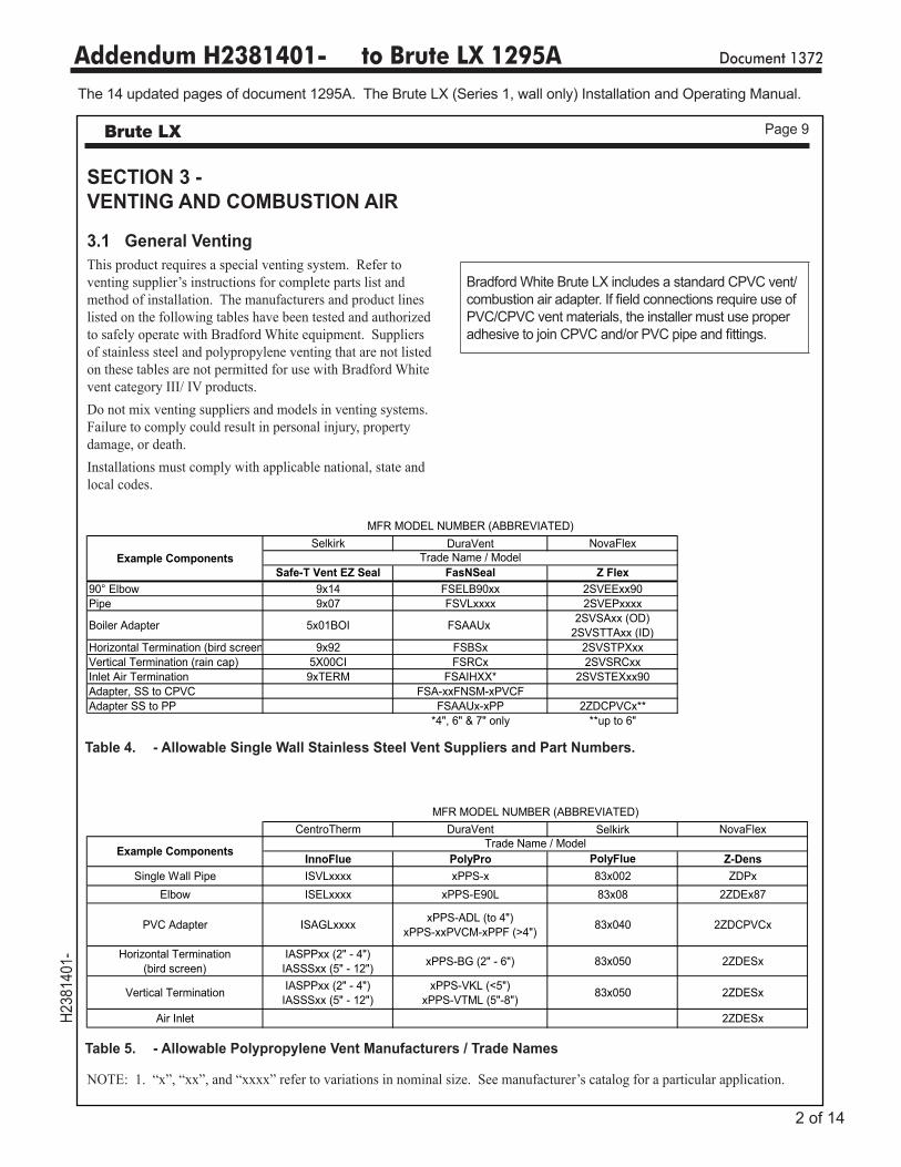
Table 4. - Allowable Single Wall Stainless Steel Vent Suppliers and Part Numbers.
Table 5. - Allowable Polypropylene Vent Manufacturers / Trade Names
SECTION 3 - VENTING AND COMBUSTION AIR
3.1 General VentingThis product requires a special venting system. Refer to venting supplier’s instructions for complete parts list and method of installation. The manufacturers and product lines listed on the following tables have been tested and authorized to safely operate with Bradford White equipment. Suppliers of stainless steel and polypropylene venting that are not listed on these tables are not permitted for use with Bradford White vent category III/ IV products. Do not mix venting suppliers and models in venting systems. Failure to comply could result in personal injury, property damage, or death.Installations must comply with applicable national, state and local codes.
NOTE: 1. “x”, “xx”, and “xxxx” refer to variations in nominal size. See manufacturer’s catalog for a particular application.
ALLOWABLE SINGLE WALL STAINLESS STEEL VENT SUPPLIERS AND PART NUMBERS
Selkirk DuraVent NovaFlex
Safe-T Vent EZ Seal FasNSeal Z Flex90° Elbow 9x14 FSELB90xx 2SVEExx90Pipe 9x07 FSVLxxxx 2SVEPxxxx
Boiler Adapter 5x01BOI FSAAUx 2SVSAxx (OD)2SVSTTAxx (ID)
Horizontal Termination (bird screen 9x92 FSBSx 2SVSTPXxxVertical Termination (rain cap) 5X00CI FSRCx 2SVSRCxxInlet Air Termination 9xTERM FSAIHXX* 2SVSTEXxx90Adapter, SS to CPVC FSA-xxFNSM-xPVCFAdapter SS to PP FSAAUx-xPP 2ZDCPVCx**
*4", 6" & 7" only **up to 6"
ALLOWABLE POLYPROPYLENE VENT MANUFACTURERS / TRADE NAMES
CentroTherm DuraVent Selkirk NovaFlex
InnoFlue PolyPro PolyFlue Z-DensSingle Wall Pipe ISVLxxxx xPPS-x 83x002 ZDPx
Elbow ISELxxxx xPPS-E90L 83x08 2ZDEx87
PVC Adapter ISAGLxxxx xPPS-ADL (to 4")xPPS-xxPVCM-xPPF (>4") 83x040 2ZDCPVCx
Horizontal Termination (bird screen)
IASPPxx (2" - 4")IASSSxx (5" - 12") xPPS-BG (2" - 6") 83x050 2ZDESx
Vertical Termination IASPPxx (2" - 4")IASSSxx (5" - 12")
xPPS-VKL (<5")xPPS-VTML (5"-8") 83x050 2ZDESx
Air Inlet 2ZDESx
MFR MODEL NUMBER (ABBREVIATED)
MFR MODEL NUMBER (ABBREVIATED)
Trade Name / ModelExample Components
Example Components Trade Name / Model
Bradford White Brute LX includes a standard CPVC vent/combustion air adapter. If field connections require use of PVC/CPVC vent materials, the installer must use proper adhesive to join CPVC and/or PVC pipe and fittings.
2 of 14

Addendum H2381401- to Brute LX 1295A Document 1372H2
3814
01-
The 14 updated pages of document 1295A. The Brute LX (Series 1, wall only) Installation and Operating Manual.
Page 11Brute LX
polypropylene, or stainless steel material is required. If the system temperatures are unknown at the time of installation, stainless, polypropylene or CPVC material is recommended.The Brute LX is a Category IV appliance and may be installed with PVC, CPVC or polypropylene that complies with ULC-S636, ANSI/ASTM D1785 F441 (see Table 6) or a stainless steel venting system that complies with UL 1738 Standard (see Table 9).
WARNINGAll vent piping just be properly supported with suitable
hangers at minimum 4 ft intervals.
WARNINGUse of cellular core PVC (ASTM F891), cellular core
CPVC, or Radel® (polyphenolsulfone) in venting systems shall be prohibited.
WARNING
Failure to use the appropriate vent material, installation techniques, glues/sealants could lead to vent failure causing property damage, personal injury or death.
WARNINGUse of cellular core PVC (ASTM F891), cellular core CPVC,
or Radel® (polyphenolsulfone) in non-metallic venting systems is prohibited and that covering non-metallic vent
pipe and fittings with thermal insulation is prohibited.
or, in absence of such requirements, follow CAN/CGA B149.
3.2.2 Ducted Combustion AirThe combustion air can be taken through the wall, or through the roof. When taken from the wall, it must be taken from out-of-doors by means of the Bradford White horizontal wall terminal, indicated in Table 7. See Table 6 to select the appropriate diameter air pipe. When taken from the roof, a field-supplied rain cap or an elbow arrangement must be used to prevent entry of rain water (see Figure 7).Use ABS, PVC, CPVC, polypropylene, or galvanized pipe for the combustion air intake requirements (see Table 8), , sized per Table 6. Route the intake to the boiler as directly as possible. Seal all joints. Provide adequate hangers. The unit must not support the weight of the combustion air intake pipe. Maximum linear pipe length allowed is shown in Table 6. 5 linear ft. (1.5m) = (1) one elbow.The connection for the intake air pipe is at the top of the unit. In addition to air needed for combustion, air shall also be supplied for ventilation, including air required for comfort and proper working conditions for personnel.
3.3 Venting (Exhaust)The flue temperature of the Brute LX changes dramatically with changes in operating water temperature. Therefore, it is necessary to assess the application of the boiler to determine the required certified vent class. If the Brute LX is installed in an application where the ambient temperature is elevated, and/or installed in a closet/alcove, CPVC,
Table 7. Vent Termination Options
Part Number Size Description239-44069-02 2" PVC Concentric Vent Terminal239-44069-01 3" PVC Concentric Vent Terminal
CA010101 2" Flush Vent Terminal PVCCA010100 3" Flush Vent Terminal PVCCA007100 3" to 5" Stainless Steel Concentric Vent Terminal
INSTALLATION STANDARDS MATERIAL UNITED STATES CANADA ABS ANSI/ASTM D1527 PVC, sch 40 ANSI/ASTM D1785 or D2665 Air pipe material must be chosen CPVC, sch 40 ANSI/ASTM F441 CPVC, sch 40, ANSI/ASTM, Polypropylene Polypropylene UL1738, ULC S636. based upon the intended application of the boiler. Single wall galv. steel 26 gauge
Table 8. Required Combustion Air Pipe Material.
3 of 14

Addendum H2381401- to Brute LX 1295A Document 1372H2
3814
01-
The 14 updated pages of document 1295A. The Brute LX (Series 1, wall only) Installation and Operating Manual.
Page 20 BRADFORD WHITE CORP.
CAUTIONCondensate is mildly acidic (pH=5), and may harm some floor drains and/or pipes, particularly those that are metal. Ensure that the drain, drainpipe, and anything that will come in contact with the condensate can withstand the acidity, or neutralize the condensate before disposal. Damage caused by failure to install a neutralizer kit or to adequately treat condensate will not be the manufacturer’s responsibility. Contact Bradford White to order Kit# A2123601 ___________________________________________
and anti-foamants that are suitable for use in the Brute LX. Please refer to the manufacturers' instructions for proper selection and application.1. Sentinel Performance Solutions Group2. Hercules Chemical Company3. Dow Chemical Company
6.5 Domestic Hot Water Piping (BMLXC)Connect domestic hot and cold water piping to the boiler at locations noted in Figure 13 through Figure 19 starting on Page 22. Expected DHW performance is indicated in Table 14. A flow switch is pre-installed on most combination models and is required. Use of flow restrictor is optional to prevent colder water at excessive flow rates. Contact Bradford White for alternate configurations.
6.6 Indirect Water Heater PipingThe BMLXH model can control an indirect water heater zone. Pipe to the locations shown in Figure 13. Setpoint is made via aqua-stat or sensor in a well located on the indirect water heater, or can be controlled at the boiler via a remote sensor. See Section 9 for control details. Sensor, Bradford White PN RE2337501
6.7 Condensate Trap InstallationThe condensate kit for your unit is part of the installation kit. See Section 1.11.
For wall mounted models sized 50 and 75 MBH, fasten the condensate trap to the condensate tray using the two hose clamps and the hose. See Figure 10. Then secure the condensate trap to the unit using the wire-tie.
A condensate drain must be installed to prevent accumulation of condensate. When a condensate pump is not used, the tubing must continuously slope downward toward the drain with no spiraling.
Consult local codes for the proper disposal method for the condensate.
Figure 10. Condensate Trap for 50 - 75 MBH Brute LX Wall
Wire-tie
Two hose clamps and the hose
Wire-tie into the bent down tab to hold condensate trap in place
View when assembled
4 of 14

Addendum H2381401- to Brute LX 1295A Document 1372H2
3814
01-
The 14 updated pages of document 1295A. The Brute LX (Series 1, wall only) Installation and Operating Manual.
Page 21Brute LX
Figure 12. Condensate Trap for 150 - 220 MBH Brute LX Wall
For wall mounted models sized 100 to 220 MBH, fasten the condensate trap to the condensate pan using the two hose clamps and the hose. See Figure 11 and Figure 12 Fasten the bracket to the bottom of the unit using the included two mounting screws. Then secure the condensate trap to the bracket using the two wire-ties.
Two mounting screwsTwo wire-ties
to fasten the condensate trap to the mounting bracket
Two mounting screws
Bra
cket
Bra
cket
Two wire-ties to fasten the condensate trap to the mounting bracket
Two hose clamps and the hose
Two hose clamps and the hose
Figure 11. Condensate Trap for 100 - 125 MBH Brute LX Wall
View when assembled View when assembled5 of 14

Addendum H2381401- to Brute LX 1295A Document 1372H2
3814
01-
The 14 updated pages of document 1295A. The Brute LX (Series 1, wall only) Installation and Operating Manual.
Page 22 BRADFORD WHITE CORP.
Figure 13. Hydronic Piping — High and low temp zones.
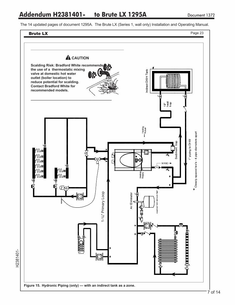
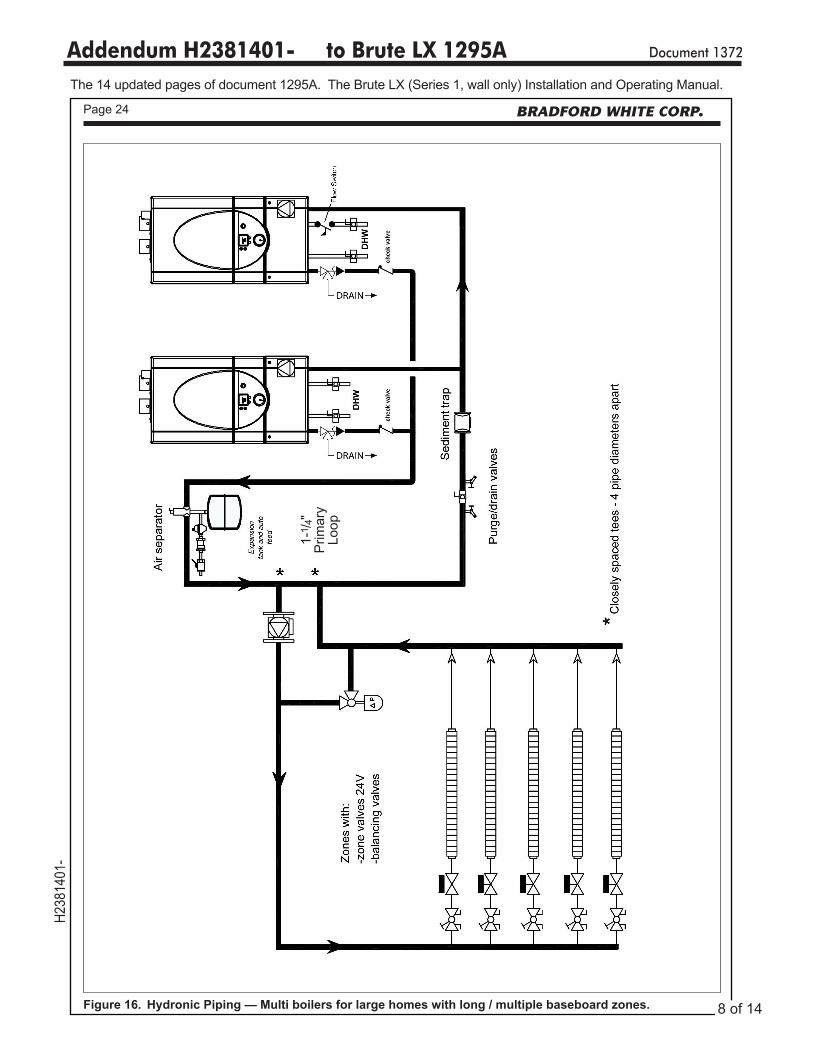
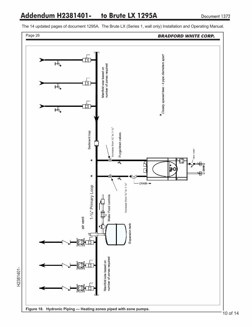
6.9 Piping SchematicsFigure 13 through Figure 19 illustrates typical piping configurations for Brute LX boilers. Although these illustrations show a wall mounted model or models, they are appropriate for floorstanding models as well and are only intended as a guide. All components or piping required by local codes must be installed in their appropriate locations.
Figure 14. DHW Connections with Flow Switch, Anti-Scald Valve and Flow Restrictor.
1-1 / 4
" Prim
ary
Loop
6 of 14
Addendum H2381401- to Brute LX 1295A Document 1372H2
3814
01-
The 14 updated pages of document 1295A. The Brute LX (Series 1, wall only) Installation and Operating Manual.
Page 23Brute LX
Figure 15. Hydronic Piping (only) — with an indirect tank as a zone.
1-1 / 4
" Prim
ary
Loop
CAUTION
Scalding Risk: Bradford White recommends the use of a thermostatic mixing valve at domestic hot water outlet (boiler location) to reduce potential for scalding.Contact Bradford White for recommended models.
__________________________________________
7 of 14
Addendum H2381401- to Brute LX 1295A Document 1372H2
3814
01-
The 14 updated pages of document 1295A. The Brute LX (Series 1, wall only) Installation and Operating Manual.
Page 24 BRADFORD WHITE CORP.
Figure 16. Hydronic Piping — Multi boilers for large homes with long / multiple baseboard zones.
1-1 / 4
" P
rimar
y Lo
op
8 of 14

Addendum H2381401- to Brute LX 1295A Document 1372H2
3814
01-
The 14 updated pages of document 1295A. The Brute LX (Series 1, wall only) Installation and Operating Manual.
Page 25Brute LX
Figure 17. Hydronic Piping — Multi boilers for large homes with long / multiple radiant zones.
1-1 / 4
" P
rimar
y Lo
op
9 of 14
Addendum H2381401- to Brute LX 1295A Document 1372H2
3814
01-
The 14 updated pages of document 1295A. The Brute LX (Series 1, wall only) Installation and Operating Manual.
Page 26 BRADFORD WHITE CORP.
Figure 18. Hydronic Piping — Heating zones piped with zone pumps.
1-1 / 4
" Prim
ary
Loop
Incr
ease
from
3 /4"
to 1
-1/ 4"
Incr
ease
from
3 /4"
to 1
-1/ 4"
10 of 14

Addendum H2381401- to Brute LX 1295A Document 1372H2
3814
01-
The 14 updated pages of document 1295A. The Brute LX (Series 1, wall only) Installation and Operating Manual.
Page 27Brute LX
Figure 19. Hydronic Piping — Heating zones piped with zone valves.
1-1 / 4
" Prim
ary
Loop
Incr
ease
from
3 / 4
" to
1-1 / 4
"
NOTE: Wall mount installation shown. Make appropriate connections for floorstanding installations.
11 of 14

Addendum H2381401- to Brute LX 1295A Document 1372H2
3814
01-
The 14 updated pages of document 1295A. The Brute LX (Series 1, wall only) Installation and Operating Manual.
Page 36 BRADFORD WHITE CORP.
8.6 Modulation ControlThe control uses a PID algorithm to adjust the firing rate of the boiler as the control point is approached. The goal of the control is to operate at a minimum firing rate to match the load on the appliance.
8.7 Pump ControlThe boiler pump is active anytime there is a call for heat applied to the control. When there is a central heat call the system pump relay is active. If there is a DHW call while the central heat call is active the system pump turns off. This happens because of domestic hot water priority, which forces the control to satisfy the domestic water demand prior to the hydronic demand. When the last heat demand is satisfied the boiler pump enters an overrun time.
8.8 High LimitThe control uses a dual thermistor sensor to monitor the Brute LX's maximum temperature. The high limit sensor is installed in the outlet water. A dual thermistor sensor is used, so that the two temperatures can be monitored and compared to confirm accuracy. The control will automatically reduce the firing of the Brute LX to prevent the high limit from tripping. The high limit setpoint is not adjustable.
8.9 Stack TemperatureThe stack temperature is a dual thermistor sensor and is limit rated. The control compares each of the temperature readings to determine accuracy. The stack sensor is used as a limiting feature to avoid excessive temperatures in the venting.
8.10 Domestic Hot Water TemperatureThe domestic hot water temperature sensor is used to control the DHW temperature. The DHW setpoint can be adjusted through the Base / Home state and the User Mode. On LX ‘C’ or Combi models, the DHW sensor is pre-installed in the DHW exchanger. On LX ‘H’ or Heat models the DHW can be can be controlled by an aquastat or optional DHW sensor installed in an indirect tank.
SECTION 9.OPERATION Modes
To access the setup parameters for configuring different Operation Modes, the installer level password most be used according to section 8.4.
9.1 Hydronic Heating DemandWhen using the Brute LX for hydronic heating a call for heat must be supplied to the "T-T or Interlock" terminals. Once the call is supplied the control energizes the boiler pump, the system pump relay, shifts the 3-way valve position and begins the ignition process. The ignition process consists of a prepurge, trial for ignition, and run period. The prepurge period starts once the fan RPM reaches a preset level. The trial for ignition period follows. The trial for ignition period
lasts 4 seconds during which the direct spark ignition system and gas valve are energized. At the end of the trial for ignition period the flame signal is compared with the preset flame threshold value. If the flame signal is higher than the flame threshold the Brute LX enters "run". If the flame signal is below the threshold the Brute LX returns to prepurge and starts the ignition process over. In "run" the Brute LX monitors the flame signal, call for heat, safeties, and water temperatures and modulates as needed between 100% and 20% of rate to satisfy the call for heat.
12 of 14
Addendum H2381401- to Brute LX 1295A Document 1372H2
3814
01-
The 14 updated pages of document 1295A. The Brute LX (Series 1, wall only) Installation and Operating Manual.
Page 37Brute LX
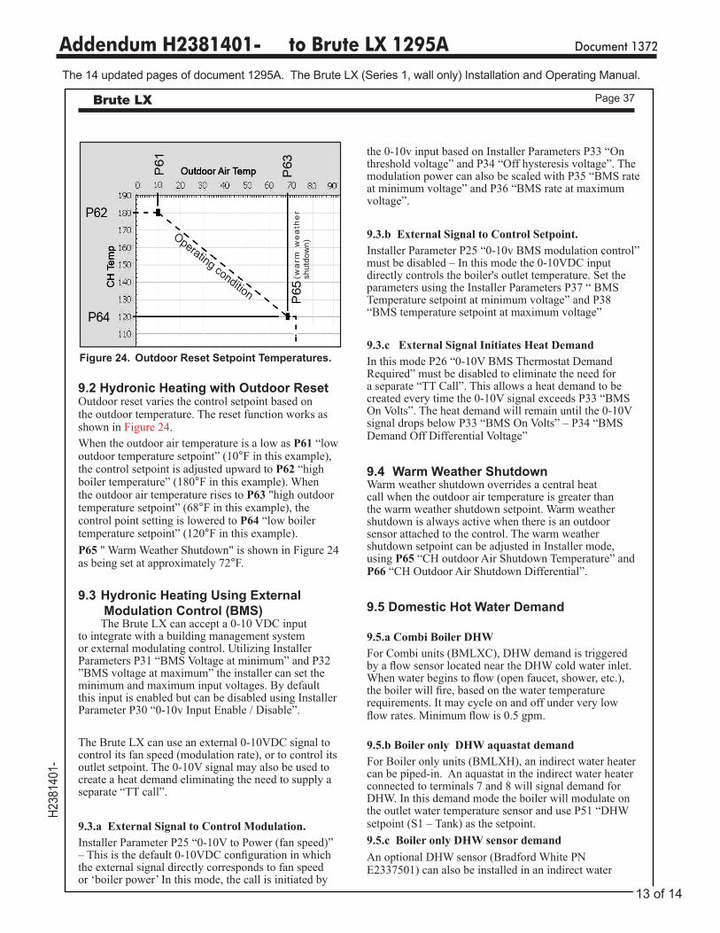
9.2 Hydronic Heating with Outdoor ResetOutdoor reset varies the control setpoint based on the outdoor temperature. The reset function works as shown in Figure 24. When the outdoor air temperature is a low as P61 “low outdoor temperature setpoint” (10°F in this example), the control setpoint is adjusted upward to P62 “high boiler temperature” (180°F in this example). When the outdoor air temperature rises to P63 "high outdoor temperature setpoint” (68°F in this example), the control point setting is lowered to P64 “low boiler temperature setpoint” (120°F in this example). P65 " Warm Weather Shutdown" is shown in Figure 24 as being set at approximately 72°F.
9.3 Hydronic Heating Using External Modulation Control (BMS)
The Brute LX can accept a 0-10 VDC input to integrate with a building management system or external modulating control. Utilizing Installer Parameters P31 “BMS Voltage at minimum” and P32 ”BMS voltage at maximum” the installer can set the minimum and maximum input voltages. By default this input is enabled but can be disabled using Installer Parameter P30 “0-10v Input Enable / Disable”.
The Brute LX can use an external 0-10VDC signal to control its fan speed (modulation rate), or to control its outlet setpoint. The 0-10V signal may also be used to create a heat demand eliminating the need to supply a separate “TT call”.
9.3.a External Signal to Control Modulation. Installer Parameter P25 “0-10V to Power (fan speed)” – This is the default 0-10VDC configuration in which the external signal directly corresponds to fan speed or ‘boiler power’ In this mode, the call is initiated by
the 0-10v input based on Installer Parameters P33 “On threshold voltage” and P34 “Off hysteresis voltage”. The modulation power can also be scaled with P35 “BMS rate at minimum voltage” and P36 “BMS rate at maximum voltage”.
9.3.b External Signal to Control Setpoint. Installer Parameter P25 “0-10v BMS modulation control” must be disabled – In this mode the 0-10VDC input directly controls the boiler's outlet temperature. Set the parameters using the Installer Parameters P37 “ BMS Temperature setpoint at minimum voltage” and P38 “BMS temperature setpoint at maximum voltage”
9.3.c External Signal Initiates Heat DemandIn this mode P26 “0-10V BMS Thermostat Demand Required” must be disabled to eliminate the need for a separate “TT Call”. This allows a heat demand to be created every time the 0-10V signal exceeds P33 “BMS On Volts”. The heat demand will remain until the 0-10V signal drops below P33 “BMS On Volts” – P34 “BMS Demand Off Differential Voltage”
9.4 Warm Weather ShutdownWarm weather shutdown overrides a central heat call when the outdoor air temperature is greater than the warm weather shutdown setpoint. Warm weather shutdown is always active when there is an outdoor sensor attached to the control. The warm weather shutdown setpoint can be adjusted in Installer mode, using P65 “CH outdoor Air Shutdown Temperature” and P66 “CH Outdoor Air Shutdown Differential”.
9.5 Domestic Hot Water Demand
9.5.a Combi Boiler DHWFor Combi units (BMLXC), DHW demand is triggered by a flow sensor located near the DHW cold water inlet. When water begins to flow (open faucet, shower, etc.), the boiler will fire, based on the water temperature requirements. It may cycle on and off under very low flow rates. Minimum flow is 0.5 gpm.
9.5.b Boiler only DHW aquastat demandFor Boiler only units (BMLXH), an indirect water heater can be piped-in. An aquastat in the indirect water heater connected to terminals 7 and 8 will signal demand for DHW. In this demand mode the boiler will modulate on the outlet water temperature sensor and use P51 “DHW setpoint (S1 – Tank) as the setpoint. 9.5.c Boiler only DHW sensor demandAn optional DHW sensor (Bradford White PN E2337501) can also be installed in an indirect water
Figure 24. Outdoor Reset Setpoint Temperatures.
Operating condition(w
arm
we
ath
er
shut
dow
n)
13 of 14

Addendum H2381401- to Brute LX 1295A Document 1372H2
3814
01-
The 14 updated pages of document 1295A. The Brute LX (Series 1, wall only) Installation and Operating Manual.
Page 41Brute LX
Make adjustments in 1/16 of a revolution increments until the CO2 is within range.
GAS TYPE CO2 (%) RANGE )
Natural 8.9 __ 9.9
Propane 9.9 __ 10.9
Table 18. CO2 Range and Pressure Settings.
Figure 25. Adjustment Screws and Settings for CO2 (Wall Mounted Brute LX)
Manifold Pressure Screw (under cap)
Adjustment Screws on Gas Valve.Close door first, before measuring CO2 Range
High-fire Adjustment (2.5 mm Hex)
+
+Low-fire Adjustment (4 mm Hex)(under slotted cap)
Note: High and Low Fire CO2 settings should be approximately equal.
200 Lafayette St.Middleville, MI 49333Warranty: (800) 531-2111
www.BradfordWhite.comLitho in U.S.A. © Bradford White 1610 Document 1372, for Brute LX
14 of 14